

Page 1
1601 J. P. Hennessy Drive, LaVergne, TN USA 37086-3565 615/641-7533 800/688-6359 Manual Part No.: 921657 18
HENNESSY INDUSTRIES INC. Manufacturer of AMMCO
®
, COATS®and BADA®Automotive Service Equipment and Tools. Revision: 06/01
Installation Instructions
Operating Instructions
Safety Instructions
Maintenance Instructions
READ these instructions before placing unit in
service. KEEP these and other materials delivered
with the unit in a binder near the machine for
ease of reference by supervisors and operators.
6000, 6002
Heavy Duty
Drum/Disc Lathe
®
Page 2

ii • AMMCO 6000, 6002 Brake Lathes
Brake Lathes
Page 3

AMMCO 6000, 6002 Brake Lathes • iii
Table of Contents
Safety Notices and Decals . . . . . . . . . . . . .iv
Warning . . . . . . . . . . . . . . . . . . . . . . . . . . . .iv
Cautions and Dangers . . . . . . . . . . . . . . . . . . . .iv
Owner’s Responsibility . . . . . . . . . . . . . . . .v
Definitions of Hazard Levels . . . . . . . . . . . .v
Important Safety Instructions . . . . . . . . . .vi
Installation
Receiving . . . . . . . . . . . . . . . . . . . . . . . . . . . . . .1
Preferred Lifting Method . . . . . . . . . . . . . . . . . . .1
Installation . . . . . . . . . . . . . . . . . . . . . . . . . . . . .1
Electrical Wiring Requirements . . . . . . . . . . . . . .2
Electrical Hook-Up . . . . . . . . . . . . . . . . . . . . . . . .2
Terminal Block Diagram . . . . . . . . . . . . . . . . . . . .2
Work Lamp . . . . . . . . . . . . . . . . . . . . . . . . . . . . .2
Lathe Operation
Operating Specifications . . . . . . . . . . . . . . . . . . .3
Work Space Requirements . . . . . . . . . . . . . . . . .3
Control Panel Functions . . . . . . . . . . . . . . . . . . . .4
Electrical Overload Safety Breaker . . . . . . . . . . . .4
Limit Switches . . . . . . . . . . . . . . . . . . . . . . . . . .4
Saddle and Cross Slide Locks . . . . . . . . . . . . . . .5
Feed Gearbox Engagement Levers . . . . . . . . . . .5
Handwheel Depth-Of-Cut Dials . . . . . . . . . . . . . .5
Gearbox Function & Handwheel Operation . . . . .6
Typical Drum Mounting . . . . . . . . . . . . . . . . . . . .7
Brake Drum Reconditioning . . . . . . . . . . . . .8 - 10
Typical Rotor Mounting . . . . . . . . . . . . . . . . . . .11
Brake Rotor Reconditioning . . . . . . . . . . . . .12 - 13
Maintenance and Service
Oiling . . . . . . . . . . . . . . . . . . . . . . . . . . . . . . . .14
Greasing . . . . . . . . . . . . . . . . . . . . . . . . . . . . . .14
Cleaning . . . . . . . . . . . . . . . . . . . . . . . . . . . . . .14
Adjusting Gibs . . . . . . . . . . . . . . . . . . . . . . . . . .14
Care of Arbors and Adapters . . . . . . . . . . . . . . .15
Drive Belt Replacement . . . . . . . . . . . . . . . . . . .16
Main Power Switch Bulb Replacement . . . . . . .16
Drive Motor Brush Replacement . . . . . . . . . . . .16
Feed Motor Brush Replacement . . . . . . . . . . . .17
Electrical Cords . . . . . . . . . . . . . . . . . . . . . . . . .17
Overload Safety Fuse Replacement . . . . . . . . . .17
Contents
Page 4

iv • AMMCO 6000, 6002 Brake Lathes
Safety
Safety Notices and
Decals
For your safety, and the safety of others, read and
understand all of the safety notices and decals included here and on the unit.
Read entire manual
before installing,
operating, or servicing this equipment.
Proper maintenance
and inspection is
necessary for safe
operation.
Do not operate a
damaged lathe.
Warning
This equipment incorporates parts such as snap
switches and power receptacles which tend to produce arcs or sparks. Theref ore, when located in a service facility, the unit should be in a room or enclosure
provided for the purpose, or should be at least 18” or
more above floor to minimize the risk of igniting fuel
vapors.
Cautions and Dangers
1. Eye and face protection requirements:
“Protective eye and face equipment is required
to be used where there is a reasonable
probability of injury that can be prevented by use
of such equipment.” OSHA 1910.133 (a).
Protective goggles, safety glasses, or a face
shield must be provided by the purchaser/user
and worn by the operator of the equipment.
Make sure all eye and face safety precautions are
followed by the operator(s). Keep bystanders out
of the area.
2. Do not remove any safety equipment, belt
guards, or shortcut controls or operations.
3. Make sure drums and rotors are properly and
squarely mounted before starting lathe, and that
all parts are secure.
4. Do not wear loose clothing, jewelry, or gloves
when operating or working around a lathe.
5. Do not overload the lathe. Read and understand
the lathe specifications. Overloading is poor
machine tool practice, shortens the life of the
lathe, and could cause a failure resulting in
personal injury.
Failure to follow danger, warning, and caution
instructions may lead to serious personal injury or
death to operator or bystander or damage to property. Do not operate this machine until you read
and understand all the dangers, warnings and cautions in this manual. For additional copies of either ,
or further information, contact:
Hennessy Industries, Inc.
1601 J.P. Hennessy Drive
LaVergne, TN 37086-3565
(615) 641-7533 or (800) 688-6359
www.Hennessy-Ind.com
WARNING
Page 5
AMMCO 6000, 6002 Brake Lathes • v
Owner’s Responsibility
To maintain machine and user safety, the responsibility of the owner is to read and follow these instructions:
• Follow all installation instructions.
• Make sure installation conforms to all applicable
Local, State, and Federal Codes, Rules, and
Regulations; such as State and Federal OSHA
Regulations and Electrical Codes.
• Carefully check the unit for correct initial function.
• Read and follow the safety instructions. Keep
them readily available for machine operators.
• Make certain all operators are properly trained,
know how to safely and correctly operate the
unit, and are properly supervised.
• Allow unit operation only with all parts in place
and operating safely.
• Carefully inspect the unit on a regular basis and
perform all maintenance as required.
• Service and maintain the unit only with
authorized or approved replacement parts.
• Keep all instructions permanently with the unit
and all decals/labels/notices on the unit clean and
visible.
• Do not override safety features.
Definitions of Hazard
Levels
Identify the hazard levels used in this manual with
the following definitions and signal words:
DANGER
Watch for this symbol:
It Means: Immediate hazards, which will result in
severe personal injury or death.
WARNING
Watch for this symbol:
It Means: Hazards or unsafe practices, which could
result in severe personal injury or death.
CAUTION
Watch for this symbol:
It Means: Hazards or unsafe practices, which may
result in minor personal injury or product or property
damage.
Watch for this symbol! It means BE ALERT! Your
safety, or the safety of others, is involved!
Safety
1. Read and follow instructions.
2. Always wear eye protection, avoid loose
clothing and jewelry.
3. Keep all guards, shields, and covers in place and
in working order.
4. Keep bystanders out of work area.
5. Unplug unit from power source before servicing
or adjusting.
6. Maintain unit properly, keep work surfaces and
work area clean.
CAUTION
Prevent accidents and injury, read and follow instructions.
DANGER
WARNING
CAUTION
Page 6

vi • AMMCO 6000, 6002 Brake Lathes
READ ALL INSTRUCTIONS
When using your garage equipment, basic safety precautions should always be followed, including the following:
1. Keep guards in place and in working order.
2. Remove adjusting keys and wrenches from the tool
before turning it on. Make this a habit.
3. Keep work area clean and well lighted. Cluttered
areas and benches invite accidents.
4.To reduce the risk of fire, do not operate equipment
in the vicinity of open containers of flammable liquids
(gasoline).
5. Adequate ventilation should be provided when working on operating internal combustion engines.
6. Care must be t aken as burns can occur from touching hot parts.
7. Do not operate equipment with a damaged cord or
if the equipment has been dropped or damaged—until it
has been examined by a qualified serviceman.
8. If an extension cord is necessar y, a cord with a current rating equal to or more than that of the equipment
should be used. Cords rated for less current than the
equipment may overheat. Care should be taken to
arrange the cord so that it will not be tripped over or
pulled.
9. To reduce the risk of electric shock, do not use on
wet surfaces or expose to rain.
10. Keep children away. All bystanders should be kept
completely away from the work area.
11. Make the workshop kid-proof. Use padlocks and
master switches, and remove starter keys.
12. Don’ t f orce a tool. It will do the job better and safer
at the rate for which it was designed.
13. Use the right tool. Don’t force a tool or an attachment to do a job for which it was not designed.
14. Dress properly. Keep hair, loose clothing, neckties,
shop rags, jewelry, fingers, and all parts of body away
from moving parts. Non-slip footwear is recommended.
15. ALWAYS WEAR SAFETY GLASSES. Everyday eyeglasses only have impact resistant lenses, they are NOT
safety glasses. Safety glasses, goggles, or a face shield
will help protect the operator from injury. Use a face
shield and dust mask during dusty operations.
16. Secure the work properly to the unit for setup and
tool bit positioning. Do not attempt to hold a drum or
rotor steady on the arbor with your hands. Both hands
must be free to operate unit.
17. Don’t overreach. Keep proper footing and balance
at all times when lathe is in operation or when working
around the unit.
18. Maintain tools with care. Keep tools sharp and
clean for best and safest performance. Follow instructions for lubricating and changing accessories.
19. Remove power from the unit and disconnect tools
before servicing and when changing accessories such as
blades, bits, cutters, etc. Follow lock-out and tag-out procedures as required.
20. Avoid unintentional starting. Make sure the switch
is in the OFF (O) position before plugging the machine in
or performing any maintenance or service work.
21. Use of improper accessories may cause risk of
injury to operator or bystanders. Use only as described in
this manual. Use only manufacturer’s recommended
attachments.
22. Never stand or lean on a lathe. Serious injury could
occur if the lathe is tipped or if the cutting tool is unintentionally contacted.
23. Check damaged parts carefully. Before further use
of the lathe, a guard or other part that is damaged should
be carefully checked. Immediately replace all damaged,
missing, or non-functional parts. Check for alignment of
moving parts, binding of moving parts, breakage of parts,
mounting, and any other conditions that may affect operation. Guards and other parts that are damaged should be
properly repaired or replaced before lathe is used again.
24. A lways feed the work into a blade or cutter and
against the direction of rotation. Cutters and tool bits are
designed to cut from the inside of a drum or rotor to the
outer edge. Do not attempt to cut from the outside edge
in to the center.
25. Never leave tools running unattended. Turn the
power off. Don’t leave the tool until it comes to a complete stop.
26. Never use compressed air to blow the tool clean.
Chips and dust may be driven between machined parts
and into bearings, causing undue wear. They may also
contact persons in the area causing personal injury.
Before operating the lathe, review the warning information on the lathe and the cautions, warnings and dangers in
this manual. Also review the following general safety instructions. Failure to follow safety instructions could result in
personal injury to operator or bystanders and damage to the lathe or personal property.
IMPORTANT SAFETY INSTRUCTIONS
SAVE THESE INSTRUCTIONS
Page 7
Installation
Receiving
The shipment should be thoroughly inspected as soon as it is
received. The signed bill of lading is acknowledgement by the
carrier of receipt in good condition of shipment covered by our
invoice.
If any of the goods called for on this bill of lading are shorted or
damaged, do not accept them until the carrier makes a notation
on the freight bill of the shorted or damaged goods. Do this for
your own protection.
NOTIFY THE CARRIER AT ONCE if any hidden loss or damage
is discovered after receipt and request the carrier to make an
inspection. If the carrier will not do so, prepare a signed statement to the eff ect that y ou hav e notified the carrier (on a specific
date) and that the carrier has failed to comply with your request.
IT IS DIFFICULT TO COLLECT FOR LOSS OR DAMAGE AFTER
YOU HAVE GIVEN THE CARRIER A CLEAR RECEIPT.
File your claim with the carrier promptly. Support your claim
with copies of the bill of lading, freight bill, invoice, and photographs, if available.
Although AMMCO’s responsibilit y ceases upon delivery of the
shipment to the carrier, we will gladly assist in tracing lost shipments. Our willingness to assist in every possible manner does
not make AMMCO responsible for collection of claims or
replacement of lost or damaged materials. Shipping damage
claims will not be handled under warranty.
Preferred Lifting Method
Lift the lathe by all four bed ways only. DO NOT lift
under the saddles, cross slides, boring bars, or spindle. Be sure the gearbox control wires and external
travel controls will not be damaged when lifting the
lathe.
Be sure the lifting slings are arranged so they will not crush or
exert pressure against any limit switch control parts, lock levers,
control wires, etc.
Both slings should be hung together in a hook or a loop of c hain
when lifting the lathe.
Installation
Bolt the lathe to the floor using the anchor bolts provided. Be
sure the lathe is resting solidly on its three feet. Shim with washers if necessary to eliminate rocking. After the lathe is bolted
down run the outer corner screws of the front support down
until they contact the floor and tighten the jam nuts. These
screws are not to be used for leveling. BEFORE RUNNING THE
LATHE, REFER TO THE OILING AND GREASING INSTRUCTIONS. Allow sufficient work space around the lathe as illustrated in the WORK SPACE REQUIREMENTS.
Brake Lathes
AMMCO 6000, 6002 Brake Lathes • 1
CAUTION
Page 8
Electrical Wir ing Requirements
The lathe is factory wired to a disconnect box whic h should be
grounded to the power supply box in accordance with local code
requirements to protect the operator from shock.
The lathe is grounded to the disconnect box through the flexible conduit. The flexible conduit should not be removed or
eliminated.
This box is to be mounted to the wall behind the machine.
A qualified electrician should complete the hook-up to line
power of 220 VAC, 50~60 Hz, Single Phase, 20 amps.
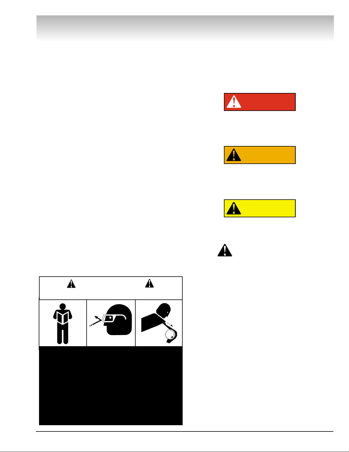
Before operating the lathe be sure the drive motors are connected at the terminal plate as shown in Fig. 1.
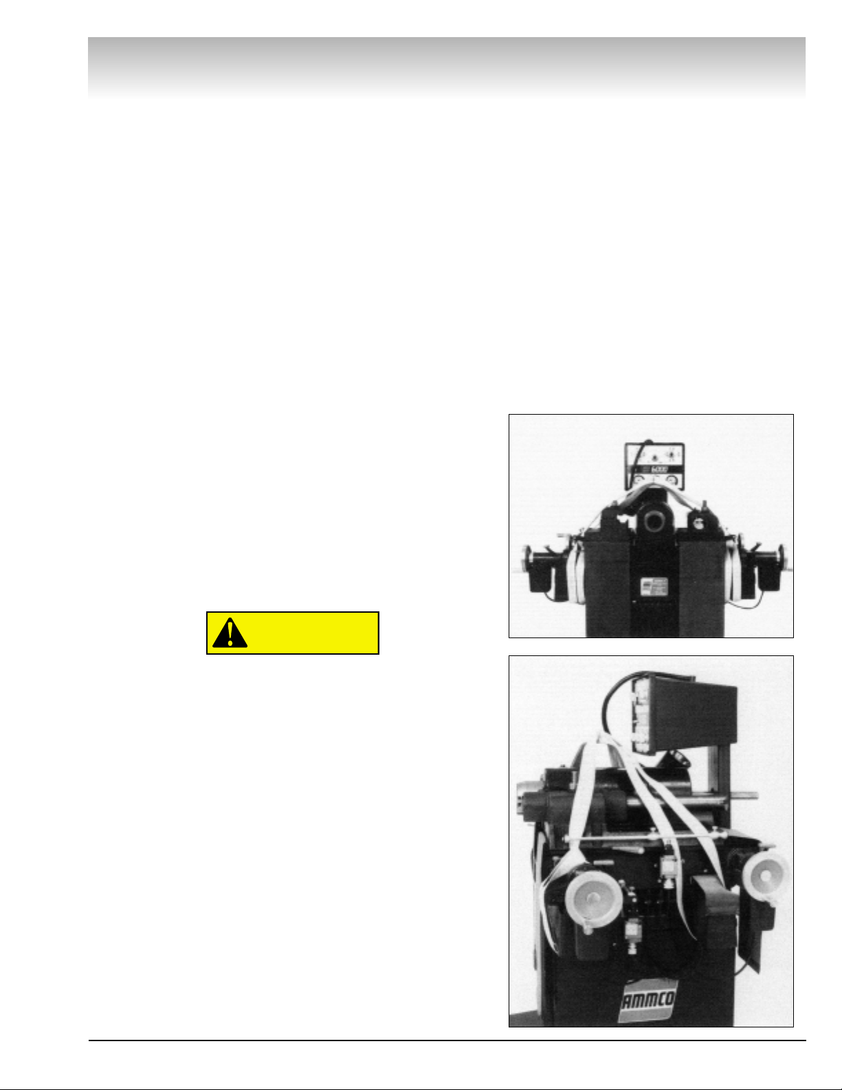
Electrical Hook-Up
Connect one incoming power line to the screw terminal at the
top of the fuse above the red lathe wire and the other power
line to the screw terminal at the top of the fuse above the black
lathe wire, Fig. 2. Check the voltage between the red and black
power lines with a voltmeter. The meter will show 220 volts
when properly wired.
Note:The incoming power lines must be supplied by the consumer and must be in accordance with local code requirements.
The incoming power lines may be colors other than red and
black.
Terminal Block Diagram
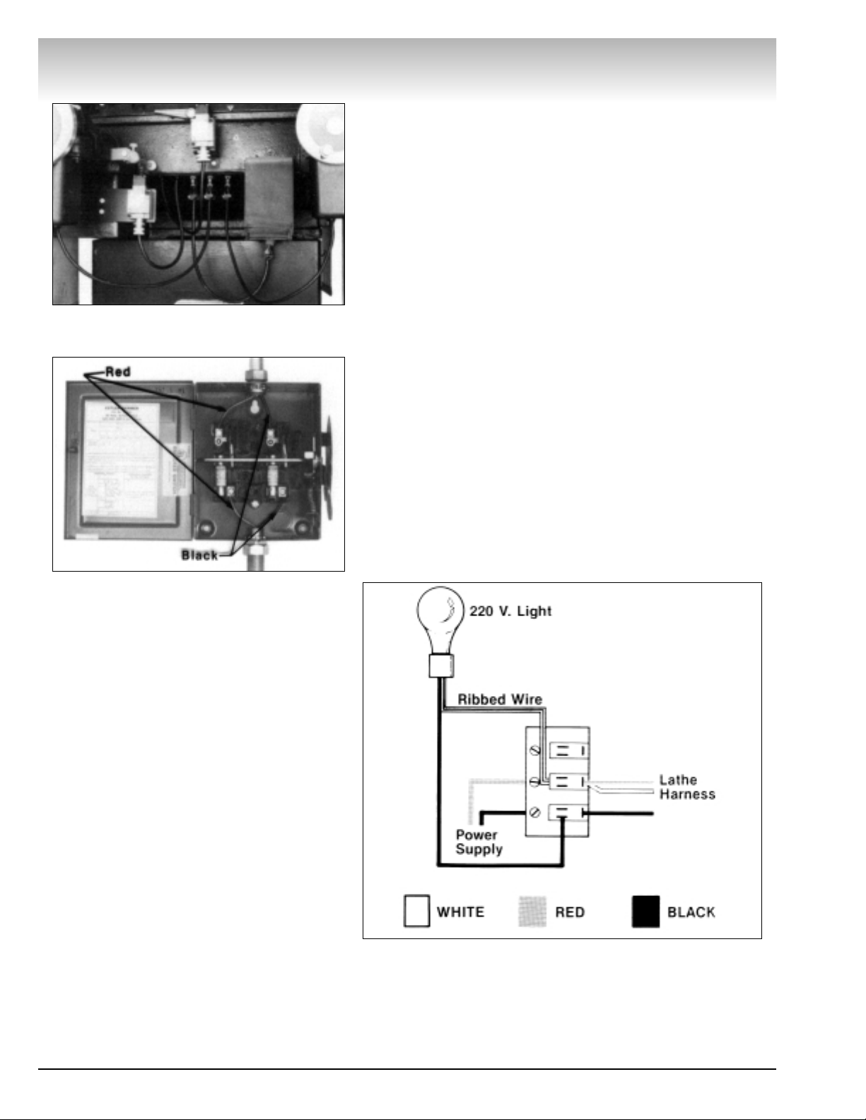
Work Lamp
The work lamp is designed for a maximum bulb wattage of 75
wat ts. Exceeding 75 w atts will damage the lamp shade. Be sure
to use 220 volt bulbs only.
Brake Lathes
2 • AMMCO 6000, 6002 Brake Lathes
Figure 1 - Drive Motor Electric Cables Connected To
Terminal Plate
Figure 2 - Disconnect Box Hook-up (Black To Black,
Red T o Red)
Page 9

Lathe Operation
Operating Specifications
Overall Lathe Height . . . . . . . . . . . . . . . . . . . . . . .57in. (1447.8 mm)
Spindle To Floor . . . . . . . . . . . . . . . . . . . . . . . . . .39 In. (990.6 mm)
Turning Travel . . . . . . . . . . . . . . . . . . . . . . . . . . . . .18 In. (457.2 mm)
Facing Travel . . . . . . . . . . . . . . . . . . . . . . . . . . . . . .7 In. (177.8 mm)
Spindle Speed, Infinitely Variable . . . . . . . . . . . . . . . . .20—140 RPM
Feed Rates, Infinitely Variable . . . . . . ..0625 In./Min, To .750 In./Min.
. . . . . . . . . . . . . . . . . . . . . . . . . . . .(1.6 mm/Min. To 19.1 mm/Min.)
Handwheel Graduations . . . . . . . . . . . . . . . . . . . ..001 In. (.020 mm)
Maximum Load, 2 1/2 In. Arbor . . . . . . . . . . . .1500 Lbs. (680.4 Kg)
Spindle Motor . . . . . . . . . . . . . . . . . . . . . . . . . .1 1/2 Hp—180 VDC
Electrical Requirements . . .220 VAC, 50/60 Hz, 1 Ph, Fused At 20 A
Lathe Weight . . . . . . . . . . . . . . . . . . . . . . . . . .1600 Lbs. (725.8 Kg)
Work Space Requirements
Brake Lathes
AMMCO 6000, 6002 Brake Lathes • 3
Page 10

Electrical Overload Safety Breaker
The control panel is equipped with an overload safety breaker
switch which will automatically turn the lathe off when the
motor is overloaded or when something is wrong in the lathe’s
electrical circuit.
To reset, wait approximately three minutes before moving the
switch to its RESET position. If the overload safety breaker continues to open, or if the line fuses are blown, have the circuit
checked by a qualified electrician.
If the feed motors do not function after resetting the safety
breaker, check the fuses on the back side of the control panel
assembly. Following the OVERLOAD SAFETY FUSE REPLACEMENT procedure.
Limit Switches
The lathe is equipped with external limit switches which can
be adjusted to stop the travel of either the saddles or cross
slides as a cut is completed. See how-to-use details under drum
reconditioning and rotor reconditioning in this section.
4 • AMMCO 6000, 6002 Brake Lathes
Brake Lathes
Control Panel Functions
Page 11

Saddle and Cross Slide Locks
The red handled saddle locks and cross slide locks tighten in a
clockwise direction. Use the locks to maintain a constant depthof-cut when machining drums (saddle locks) and turning rotors
(cross slide locks). Never engage a feed gearbox when its saddle or cross slide is locked, Fig. 1.
Feed Gearbox Engagement Levers
Each gearbox is labeled to indicate the ENGAGE and DISENGAGE positions. The gearboxes may be shifted in and out of
gear at any feed speed without danger to the gearboxes.
Hand Wheel Depth-Of-Cut Dials
The hand wheel dials are calibrated with both inch and metric
scales. The dials indicate the DEPTH-OF-CUT when setting the
cutting tool for turning a drum.
Inch Scale - A cut of .010" from a 16.000" diameter drum will
result in a refinished diameter of 16.020".
Metric Scale - A cut of .1 mm from a 418 mm diameter drum
will result in a refinished diameter of 418.2 mm.
Brake Lathes
AMMCO 6000, 6002 Brake Lathes • 5
Figure 1 - Saddle & cross slide locks.
Figure 2 - Engagement Lever Operation
Page 12

6 • AMMCO 6000, 6002 Brake Lathes
Brake Lathes
Gearbox Function & Handwheel Operation
Page 13

AMMCO 6000, 6002 Brake Lathes • 7
Typical Drum Mounting
Large Truck Drum Mounted On 2 1/2" Arbor
A — Arbor
B — Arbor Nut
C — Arbor Washer
D — Spacers
E — Centering Cones Used As Spacers
F — Centering Cones
G — Lathe Spindle
H — Draw Bar
Floating Type Drum Mount ed On 1 7/8" Arbor
A — Arbor
B — Arbor Nut
C — Spacers
D — Clamping Cups
E — Centering Cone
F — Spring
G — Lathe Spindle
H — Draw Bar
Hub Type Drum Mounted On 1" Arbor
A — Arbor Nut
B — Arbor
C — Self-Aligning Spacer
D — Radii Adapters
E — Lathe Spindle
F — Draw Bar
Hub Type Drum Mounted On 11/16" Arbor
A — Arbor Nut
B — Self-Aligning Washers
C — Spacer
D — Centering Cone
E — Arbor
F — Lathe Spindle
G — Draw Bar
Brake Lathes
Page 14

Brake Drum Reconditioning
Although drum turning is usually done on the right side of the
lathe, the left side may also be used by turning the boring bar
upside down in the left hand boring bar clamp.
The following description assumes right hand operation:
1. Measure the diameter of the drum with a brake drum
micrometer. If the drum diameter will be larger than the manufacturer’s specified rebore limit after machining, it must be
replaced. Be sure the general condition of the drum is good.
2. Before mounting a hubbed brake drum, inspect the bearings and races for wear. Chec k a lubricant sample from the bearings for metal particles. An abundance of shiny metal chips
indicate a damaged bearing. Install a new bearing race before
machining the drum. Also, check the hub for a loose race. If the
bearing race can be turned by hand the race recess is worn.
Replace the hub or hub and drum. New bearing races are usually installed in the hub during manufacturing. Be sure the races
are fully seated in the hub. New bearings should be used with
new races.
3. Mount the drum on the arbor using appropriate adapters,
cones, and spacers. See TYPICAL DRUM MOUNTING illustrations.
4. Wrap a drum silencer band snugly around the drum and
secure it by sliding the buckle finger under the top layer of the
band.
5. Place the boring bar in the boring Bar clamp. Crank the
saddle to its innermost position, then back it out 2 turns.
Position the cross slide so it is close to the open side of the
drum; be sure the drum will not touch the cross slide when the
lathe is turned ON.
6. Position the boring bar and clamp so the inside corner of
the drum can be reached with the tool, and so the boring bar
and clamp will not run into the spindle housing as the cross slide
feeds out. Give the saddle hand wheel one full t urn clockwise to
move the tool away from the drum.
7. Set the cross slide limit switch by either estimating the
travel necessary to cut the full depth of the drum or, if cutting
several drums having the same depth, crank the cross slide
back so the tool bit is 1/4" to 1/2" outside the drum. be sure all
feed gearbox levers are in the DISENGAGE position. TURN THE
LATHE ON. Slide the left adjustable travel limit stop against the
microswitch plunger, Fig. 3. The feed motor will shut off as the
ramp of the adjustable stop depresses the microswitch plunger.
Tighten the lockscre w to hold the stop at this point. Set the right
hand feed direction knob to the DRUM TURN OUT position.
8. Crank the tool bit to the middle of the drum wall. Manually
advance the tool bit until it lightly contacts the drum wall making a “scratch” cut.
Brake Lathes
8 • AMMCO 6000, 6002 Brake Lathes
Figure 3 - Setting Limit Switch for Drum Turning
Page 15

Note: A “scratch” cut should be no more than .001" deep. If
the “scratch” cut is too deep it will show a continuous line on
the face of the drum and the runout will not be apparent. Back
the tool bit off, stop the lathe, and check the mounting as follows:
A. Loosen the arbor nut and rotate the drum one-half turn
(180º) on the adapters.
Note: The adapters must be held to keep them from turning.
Retighten the arbor nut, turn the lathe ON, and make a second
“scratch” cut. Turn the lathe OFF.
B. If the first and second “scratch” cuts are side-by-side,
the runout is in the drum — not in the mounting.
Note: A very small amount of runout is permissible. A large
amount of runout indicates either a bent drum or an incorrect
mounting.
If the “scratch” cuts are opposite each other (180° apart), the
drum is not properly mounted. Shut the lathe OFF. Inspect the
mounting for cleanliness and the adapters for burrs, nicks, or
scratches. Check the bearing races for looseness. Remount the
drum and check again for runout. Proceed to machine the drum,
if the runout has been corrected.
9. Turn the lathe ON. Carefully advance the tool bit by hand
until it just contacts the drum surface and makes a "scratch" cut.
Hold the saddle hand wheel in this position and rotate its dial to
the (0) position. This setting will be the reference used to help
determine the reconditioned diameter of the drum.
10. Align the tool bit with the deepest groove worn in the
drum. Start the lathe and manually advance the tool bit into the
bottom of the groo ve until it makes a continuous cut around the
drum. Do not cut any deeper than necessary to make the cut
continuous. The depth-of-cut dial will show the approximate
amount of material that must be removed to recondition the
drum. Double the depth-of-cut reading and add the result to the
brake drum micrometer reading to find the finished diameter of
the reconditioned drum. This calculated measurement must be
compared with:
a. The maximum rebore limit (available from the
manufacturer’s specifications).
b.The measured diameter of the drum before machining to
determine the amount of material to be removed in each
pass.
11. With the lathe still running, give the saddle hand wheel
one full turn clockwise to move the tool bit away from the drum
wall. Manually position the tool bit at the inside corner of the
drum and set the desired depth of cut. Engage the feed gearbo x
and set the feed speed.
Brake Lathes
AMMCO 6000, 6002 Brake Lathes • 9
Figure 4 - Drum Mounting, First “Scratch” Cut
Figure 5 - Drum Mounting, Second “Scratch” Cut
Page 16

Note: FEED AND SPEED SETTINGS—The following spindle
speed and feed speed recommendations are intended to serve
as a starting point for a machine operator not familiar with the
lathe.
Drums Spindle Speed Feed Speed
Up To 12" Dia. Medium Fast Medium Slow
Over 12" Dia. Medium Medium Slow
Note: See CONTROL PANEL FUNCTIONS.
Although these settings are relatively slow, they should give
the manufacturer’s recommended finish and good tool life. The
settings may be increased considerably, however, tool life
decreases as spindle and feed speeds increase.
12. If a finish cut is to be made simultaneously with the
rough cut or a rough cut and grind are to be done at the same
time, repeat steps 5, 6, and 7 on the left side of the lathe.
Note: Both the lathe and the grinder must be running when
the grinder is moved into contact with the drum.
Start the second (finish) cut at least one inch behind the rough
cut. Find the zero setting for the left side by carefully advancing
the tool bit or grinder (both the lathe and the grinder must be
running) by hand until it makes light contact with the drum. Set
the micrometer dial to zero. Advance the tool bit to the desired
depth for the finish cut and tighten the saddle loc k lev er. Engage
the saddle feed gearbox and set the feed speed.
Disengage the feed gearbox and shut the lathe off when the
cut is completed.
Note: Determine the depth-of-cut by these general guidelines:
• Finishing cuts should not be shallower than .002 inches (.05
mm).
• Usually no more than two cuts are required to recondition a
drum.
Brake Lathes
10 • AMMCO 6000, 6002 Brake Lathes
Page 17

AMMCO 6000, 6002 Brake Lathes • 11
Brake Lathes
Typical Rotor Mounting
Large Truck Rotor Mounted On 2 1/2" Arbor
A — Arbor
B — Arbor Nut
C — Arbor Washer
D — Spacers
E — Centering Cones
Used As Spacers
F — Centering Cones
G — Lathe Spindle
H — Draw Bar
Hub Type Rotor Mounted On 1" Arbor
A — Arbor Nut
B — Arbor
C — Self-Aligning Spacer
D — Radii Adapters
E — Lathe Spindle
F — Draw Bar
Page 18

Brake Rotor Reconditioning
Each brake rotor should be carefully inspected for scoring,
hard spots, and rust ridges at the inner and outer circumferences of the rotor. Any excessive wear or deformity should be
noted and, the rotor should be replaced if not within acceptable
limits. The twin cutter is designed to be used on the left cross
slide in place of the boring bar clamp, to refinish both sides of a
rotor at the same time. The cross slide centers the twin cutter
to the rotor and the saddle feeds the twin cutter out when cutting.
1. Use a micrometer to check the thickness of the rotor at
three or more points around the circumference and about 1"
(2.54 cm) in from the outer diameter. If the thickness is less
than specified by the manufacturer at any point measured, or
will be less after machining, the rotor should be replaced.
2. Before mounting a hubbed rotor inspect the bearings and
races for wear. Check a sample of lubricant from the bearings
for metal particles. An abundance of shiny metal chips indicates
a damaged bearing. Install a new bearing race before machining
the rotor . Also, chec k the hub for a loose race. If the bearing race
can be turned by hand the race recess is worn. Replace the hub
or hub and rotor. New bearing races are usually installed in the
hub during manufacturing. Be sure the races are fully seated in
the hub. New bearings should be used with new races.
3. Mount the rotor on the arbor using the appropriate
adapters, cones and spacers. See the TYPICAL ROTOR
MOUNTING illustrations.
4. Install a silencer band by stretching it around the rotor and
hooking the wire loop over a lead weight.
5. Center the twin cutter to the rotor by manually moving the
cross slide forward or back so the rotor is evenly spaced
between the tool bits. Lock the cross slide in place.
6. Unlock the twin cutter tool slides and adjust them so they
are equally spaced from the center of the rotor.
7. Loosen the boring bar clamp nuts of the twin cutter and
position the boring bars so approximately one-half of their
length is forward of the clamp studs. Manually advance the saddle until the outer boring bar tool bit comes in contact with the
hub at the face of the rotor. Be sure the rotor has clearance with
the body of the twin cutter in this position. Wrench tighten the
outer clamp nut. Position the inner boring bar so its tool bit is
approximately 1/2" beyond the rotor face and wrench tighten its
clamp nut. Lock the tool slides in these positions. Be sure the
tool bits are not in contact with the rotor.
8. Set the saddle travel limit switch by either estimating the
travel necessary to cut the full width of the rotor faces or, if cutting several rotors having the same outside diameter, crank the
saddle out so the tool bits are 1/4" to 1/2" outside the rotor. Be
sure all feed gearbox levers are in the DISENGAGE position.
Slide the adjustable travel limit stop against the microswitch
plunger, Fig. 6. The feed motor will shut off as the ramp of the
Brake Lathes
12 • AMMCO 6000, 6002 Brake Lathes
Figure 6 - Setting Limit Switch For Face Cut
Clearance
Adjustable T ravel Limit Stop
Microswitch Plunger
Page 19

adjustable stop depresses the microswitch plunger. Tighten the
lock screw to hold the stop at this point.
9. Advance the tool bits to the approximate center of the rotor
faces. Turn the red and blue depth-of-cut knobs clockwise, one
at a time, until their respective tool bits make light contact with
the rotor face, making a “scratch” cut, Fig. 7.
Note: A “scratch” cut should be no more than .001" deep. If
the “scratch” cut is too deep it will show a continuous line on
the face of the rotor and the runout will not be apparent. Hold
the outer knobs still and turn the inner dials to zero (choose
either inches or millimeters). Back the tool bits away from the
rotor by turning the knobs counterclockwise. Turn the lathe OFF.
10.To check the rotor mounting:
A. Loosen the arbor nut and rotate the rotor one-half turn
(180°) on the adapters.
Note: The adapters must be held to keep them from turning.
Retighten the arbor nut. Back the saddle out one hand wheel
turn and start the lathe. Make a second “scratch” cut on the
outer surface of the rotor only. Turn the lathe OFF.
If the “scratch” cuts are side by side any runout or wobble is
caused by the rotor’s condition.
B. If the “scratch” cuts are opposite each other (180º
apart), the rotor is not properly mounted. Remove the rotor
from the arbor and examine each adapter and the arbor for
nicks, burrs, chips, dirt, and rust. Also inspect the rotor hub
for loose or damaged bearing cups. Clean, repair, remount,
or replace as necessary.
11. Check the settings of the depth-of-cut dials again. Move
the tool bits in until they lightly contact the rotor faces and reset
the dials to zero if necessary.
12. St art the lathe and manually advance the saddle to position the outer tool bit at the rotor hub. Set the dial knobs for the
desired depth of cut (inches or millimeters). Set the spindle
speed and set the left hand f eed direction knob to the FACE CUT
OUT position. Engage the saddle feed gearbox.
Note: The following spindle speed and feed speed recommendations are intended to serve as a starting point for a
machine operator not familiar with the lathe.
Rotors Spindle Speed Feed Speed
Up To 12" Dia. Fast Medium Slow
Over 12" Dia. Medium Medium Slow
Note: See CONTROL PANEL FUNCTIONS.
Although these settings are relatively slow they should give
the manufacturers recommended finish and good tool life. The
settings shown may be increased considerably; however, tool
life decreases as spindle speed and feed speed are increased.
When the cut is completed, disengage the feed gearbox and
shut the lathe OFF.
Brake Lathes
AMMCO 6000, 6002 Brake Lathes • 13
Figure 7 - Rotor Mounting, First “Scratch” Cut
Figure 8 - Rotor Mounting, Second “Scratch” Cut
Page 20

Maintenance and Service
Oiling
The lathe is initially greased and the bare metal parts are
coated with an oil-soluble rust preventative at the factory. It is
not necessary to clean the rust preventative from these parts.
Before using the lathe, however, all bare metal parts (ways,
spindle, cross slides, etc.) should be wiped down with an oiled
rag. Use a light machine oil or way oil for the initial wipe down
and daily when oiling the bare metal parts. Keep the wipers
oiled by applying light machine oil to their top edges daily.
Greasing
Automotive chassis grease should be applied to the grease fittings called out in Figs. 1, 2 & 3 weekly using the hand grease
gun supplied with the lathe.
Sides (Right Side Illustrated), Fig. 1:
Align the red triangle index marks (1). Apply grease to the lead
screw nut fitting (2) located on top of the cross feed. Also,
grease the cross slide way fitting (3) and the rear saddle way fitting (4). Follow the same procedure when greasing the left side.
Rear (Right Rear Illustrated), Fig. 2:
With the lathe turned OFF, reach up under each saddle at the
back of the lathe and wipe grease onto the driving shaft gears
of the cross slide gear boxes.
Front (Front Right Illustrated), Fig. 3:
Fold the cross slide dove tail cover back. Align the red triangle
index marks (5). Apply grease to the saddle fitting (6) and the
lead screw nut fitting (7) located inside the hole in the front of
the saddle. Follow the same procedure when greasing the front
left side.
Motor Bearings: The motor bearings are sealed for life and
need no maintenance.
Cleaning
Keep the lathe as clean as possible for trouble free operation
as well as safety and longer lathe life. Use a brush to sweep
metal chips and dust of f the lathe. DO NOT USE COMPRESSED
AIR TO BLOW THE LATHE CLEAN as chips and dust may be
driven between machined parts and into bearings, and cause
undue wear.
Adjusting Gibs
The gibs, Figs. 1 & 3, should be adjusted periodically to minimize looseness in the slides and to obtain the best possible finish on the work. When adjusting the gibs, the cross slide and
the saddle must not overhang either end of their respective
dove tails. Tighten one gib adjusting screw then back it off until
the slide moves smoothly. Run the slide back and forth by hand
to check your adjustment. Repeat a second time if necessary.
Go through the same procedure for eac h individual gib adjusting
screw.
Brake Lathes
14 • AMMCO 6000, 6002 Brake Lathes
Figure 1 - Grease Fittings (Right Side Shown)
Figure 2 - Apply Grease To The Gear (Right Rear
Shown From Underneath)
Figure 3 - Grease Fittings (Right Front Shown)
Cross Slide Gib
Saddle Gib
1
2
3
4
5
6
7
Page 21

Care of Arbors and Adapters
Although the adapters, arbors, and the spindle are
made of top grade steel and are turned, hardened,
and precision ground to close tolerances, great care
should be taken in their use, handling, and storage.
Even the smallest nick, scratch, or loose chip can
cause incorrect rotor or drum alignment and the
result will be inaccurate machining.
Always inspect the faces and the seating tapers of each
adapter . Wipe each adapter clean before and after use. Carefully
correct any flaw with a fine stone. If the damage cannot be corrected, replace the part.
Handle and store arbors and adapters with great care. Keep
them clean and oiled with light machine oil. DO NOT dump
them together in a box to collect nic ks and dirt. DO NOT use the
adapters for any other purpose than they are intended.
Remove all adapters from the arbor after machining a drum or
rotor and wipe them clean - especially the inboard adapter.
When a finished drum or rotor is removed from the arbor, the
inboard adapter may move slightly away from the face of the
arbor and allow chips or dust to fall into the opening. If these
chips are not cleaned from between the arbor face and the
adapter, they may adversely affect the machining of the next
brake part.
Brake Lathes
AMMCO 6000, 6002 Brake Lathes • 15
CAUTION
Page 22

Drive Belt Replacement
When replacing drive belts, the following procedure must be
followed:
1.Turn the wall switch OFF.
2. Remove the arbor and drawbar from the spindle.
3. Remove the upper and lower belt guards.
4. Remove the spindle pulley and the spindle belt.
5. Remove the counter shaft bushing and the counter shaft
belt.
6. Remove the access door, then the motor pulley and the
motor belt.
To remove the motor pulley:
a. Remove both set screws.
b. Insert a set screw into the threaded hole and tighten.
This will loosen the bushing, Fig. 4.
To install the motor pulley:
a. Clean the motor shaft, the bore, the outside of the
bushing, and the hub bore of all oil and dirt.
b. Insert the bushing in the hub and match the hole
pattern.
Note: Each hole will be threaded on one side only.
c. Oil the set screws and thread them into the holes
indicated in Fig. 4.
d. Alternately tighten the set screws. Torque to 175 in. lbs.
(1210 bushing - with 3/8 screws) or 55 in. lbs. (10 08
bushing - with 1/4 screws).
To install new timing belts, rev erse the procedure. Be sure the
motor pulley is correctly aligned.
Main Power Switch Bulb Replacement
1. Remove the red lens bezel by unscrewing it in a counter-
clockwise direction.
2. Pull gently on the black ring around the bulb to eject it.
3. Push the new bulb into the socket and replace the lens.
Drive Motor Brush Replacement
1.Turn the lathe OFF and turn the wall switch to its OFF posi-
tion.
2. Unscrew the brush retaining plugs from the motor and
remove the brushes, Fig. 5.
3. Install the new brushes and replace the retaining plugs.
Brake Lathes
16 • AMMCO 6000, 6002 Brake Lathes
Figure 5 - Drive Motor Brush Replacement
Figure 4 - Motor Pulley Removal & Installation
Page 23

Feed Motor Brush Replacement
1.Turn the wall switch OFF. Remove the motor cover and dis-
connect the electrical connector.
2. Unscrew the brush retaining plugs from the motor and
remove the brushes. Note how the brushes are positioned in
the motor, Fig. 6.
3. Inst all the new brushes so they contact the commutator
correctly.
4. Replace the retaining plugs, connect the electrical wires,
and replace the motor cover.
Electrical Cords
Replace or repair any damaged or worn cords immediately.
Overload Safety Fuse Replacement
1. Turn the wall mounted disconnect box off.
2. Remove the scre ws holding the control panel in the control
box and pull the control panel assembly out.
3. Disconnect the lathe harness connector from the panel.
4. Remove the four screws from the shield to gain access to
the fuses, Fig. 7.
Brake Lathes
AMMCO 6000, 6002 Brake Lathes • 17
Figure 6 - Feed Motor Brush Replacement
Figure 7 - Safety Fuse Replacement
Page 24

921657 18 06/01 © Copyright 1993 Hennessy Industries and AMMCO All Rights Reserved Printed in USA
 Loading...