

Page 1

904850
Brake Drum Grinder
Installation and
Operation Instructions
with Maintenance Instructions
and Parts Identification
READ these instructions before placing unit in
service. KEEP these and other materials delivered
with the unit in a binder near the machine for
ease of reference by supervisors and operators.
1601 J. P. Hennessy Drive, LaVergne, TN USA 37086-3565 615/641-7533 800/688-6359 Manual Part No.: 921203 07
HENNESSY INDUSTRIES INC. Manufacturer of AMMCO
®
, COATS®and BADA®Automotive Service Equipment and Tools. Revision: 10/06
®
The No. 904850 Brake Drum Grinder
is a precision grinder used in brake
drum refinishing. The high-speed
grinding wheel produces a very even
finish on the drum braking surface by
grinding away any raised hard spots
that have not been removed in normal machining with the carbide cutting tool.
Page 2
2 •
AMMCO Brake Drum Grinder
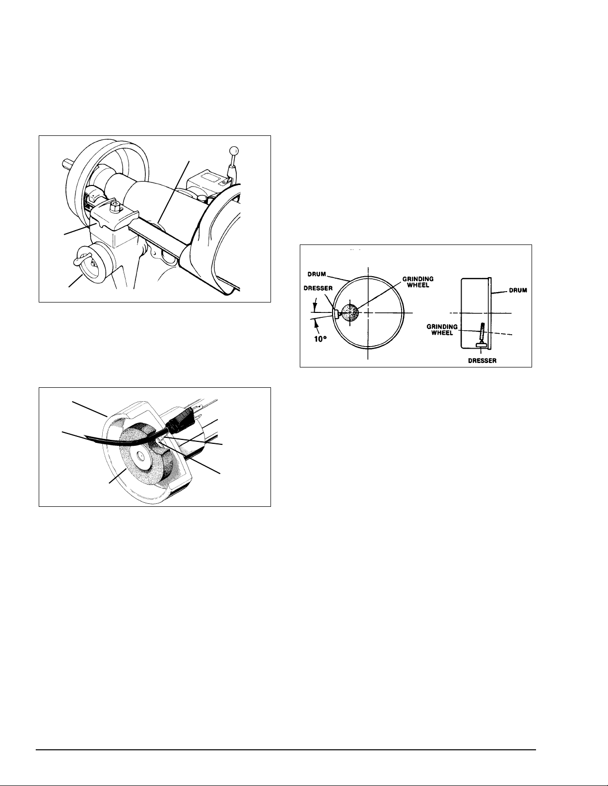
GRINDER INSTALLATION
After the first brake drum has been turned, remove
the boring bar from the clamp and place the grinder in
position, Fig. 1. DO NOT overtighten the clamp on
the grinder spindle housing. For proper setup, be
sure to move the lathe spindle manually to its full back
position. DO NOT plug in the grinder power cord
until the grinder is completely setup.
Figure 1 - Grinder Installation
MOUNTING THE GRINDING WHEEL
To mount the grinding wheel, insert the Grinding
Wheel Removal Tool, (Item 28) on the parts drawing,
through the spindle housing to lock the spindle. Install
the new wheel, Fig. 2.
Figure 2 - Mounting The Grinding Wheel
Before proceeding further, the grinding wheel must
be dressed. Dressing cleans, shapes, and trues the
surface of the grinding wheel. Refer to the instruction
sheet for the No. 906061 Grinding Wheel Dresser
(PN/921109).
SAFETY PRECAUTIONS: When dressing a grinding wheel, extra care must be taken to protect the
operator. The lathe must not be turned on while
dressing the grinding wheel with a drum-mounted
dresser. Be sure the dresser is removed from the
drum before starting the lathe.
GRINDING WHEEL DRESSING
The No. 906061 Diamond Wheel Dresser is used to
true the surface of the grinding wheel to be parallel
with the surface of the machined drum. The diamond
nib cleans and shapes the wheel to assure full grinding wheel contact.
The grinding wheel is normally dressed one time to
finish grind one set of brake drums. However, if the
grinding wheel gets dull or “loaded”, redress it.
Dressing takes but a moment-don’t overlook it. Note
that the Grinding Wheel should be dressed before finishing each drum.
1. The dresser is magnetically held inside the drum
on the same surface that will be ground. Visually align
the diamond tip 10-degrees below the center of the
Grinding Wheel, as shown in Fig. 3. This is particularly
important when dressing the Grinding Wheel at an
angle, Figure 4.
The Drum Grinder should be securely mounted in the
Boring Bar Clamp of the Lathe.
It may be necessary to remove the silencer band
when mounting the dresser.
Figure 3 & 4 - Visually Align Diamond Tip
2. Make sure that the grinding wheel will clear the
brake drum after it passes the diamond nib. Manually
move the lathe spindle back and forth to check this.
Use the cross feed hand wheel to adjust clearances.
CAUTION: The grinding wheel spins at a high
speed. DO NOT use a damaged wheel. DO NOT
use the grinder with the wheel guard removed.
WEAR SAFETY GOGGLES AT ALL TIMES!
3. Plug in the grinder power cord and turn the switch ON.
Use the cross feed hand wheel to move the grinding
wheel until it just touches the diamond. Using the
spindle feed hand wheel, manually move the diamond
tip back and forth across the grinding wheel face. Set
the depth-of-cut at about .005" (.127 mm) per pass.
Dress the grinding wheel until its full face is parallel to the drum wall. DO NOT overdress or use
too fast a spindle feed. Moving the dresser across
the wheel too fast will leave too rough a surface on
the face of the wheel.
4. After dressing a wheel, do not change the position
of the Boring Bar Clamp in which the Grinder is
mounted. Remove the Dresser from the drum wall
and, after loosening the knurled set screw, rotate the
diamond nib slightly. This will help keep the nib
pointed and prolong its life — as well as set it up for
the next dressing job.
Spindle Housing
Boring
Bar
Clamp
Cross Feed Handwheel
Grinding Wheel Guard
Power Cord
Grinding Wheel
Removal
Tool
Hole
Figure 4
Figure 3
Page 3

AMMCO Brake Drum Grinder
• 3
GRINDING THE DRUM
Brake drums may be finished in either of two ways:
Two Step Process - Each brake drum is mounted on
the brake lathe arbor, rough turned and then finish
ground before moving on to the next drum. Only the
boring bar and the grinder are interchanged to maintain the absolute accuracy that is necessary for the
professional brake job. DO NOT turn all the drums
then remount and grind each one.
One Step Process - Brake drums with little wear or
those with no out-of-round distortions may simply be
finish ground without prior machining. DO NOT
exceed the recommended depth-of-grind .002" to
.005" (.051 to .127 mm) on any one pass.
The position of the clamp must not be changed
until the set of drums for which the grinding wheel
was dressed have been ground.
Remove the dresser from the drum wall. Check to be
sure that the lathe motor switch is OFF. Adjust the
lathe spindle manually to bring the drum back over the
grinding wheel as far as possible. It may be necessary
to turn the wheel guard on the grinder spindle to gain
clearance. Loosen the wheel guard cap screw to do
this, but DO NOT remove the wheel guard. Also it is
wise to turn the drum by hand for at least one revolution to make sure that everything is clear.
CAUTION: Always wear safety glasses while
operating grinder.
1. Set the lathe spindle speed to its slowest R.P.M.
2. Start the grinder and the lathe.
3. Use the cross feed handwheel to move the grind-
ing wheel into contact with the drum wall.
4. Set the depth-of-grind from .002" to .005" (.051 to
.0127 mm).
5. Set the infimatic spindle feed from .008" to .010"
(.203 to .254 mm). Engage the feed mechanism.
6. Set the feed stop so that the spindle will automatically stop feeding when the grinding wheel clears the
drum.
Turn, then grind each of the remaining drums of the
set in the same manner. Remember—it is not necessary to dress the grinding wheel for each drum—only
when the grinding angle is changed, when the wheel
becomes “loaded” or dull, or when a new wheel is
installed.
NOTE: Figure 5 illustrates the positioning of the
boring bar clamp for large and small drums. Once
setup for one or the other, the tool post pivot set
screw is locked.The boring bar clamp is not moved
when the boring bar is exchanged with the
grinder.
Figure 5
Hubless drum 10" (254 mm) and smaller may also be
turned and finish ground on AMMCO lathes. These
smaller drums must be mounted differently than full
size types. The larger diameter hubless adapter
(shown in Fig. 6a) on the inside of the drum is NOT
used. Instead, an appropriately sized centering cone
and a spacer are used on the inside with the hubless
adapter on the outside. This clears a working area for
both cutting and grinding, Fig. 6b.
Figure 6a - Mounting For Hubless Drums Over 10" (254mm)
Figure 6b - Mounting For Hubless Drums 10" (254mm) And
Under
Boring Bar Clamp
Swiveled For
Large Diameter
Brake Drums
Swiveled For
Small Diameter
Brake Drums
Centering
Cone
Arbor Nut
Spacer
Cross Section Of Hubless Brake Drum
Self-Aligning
Spacer
Hubless Adapter
Cones
Centering
Cone
Arbor Nut
Cross Section Of Hubless Brake Drum
Self-Aligning
Spacer
Hubless
Adapter
Cone
Page 4

PART
ITEM NO. QTY. DESCRIPTION
*1 910245 1 Grinding Wheel
2 910990 1 Grinding Wheel Guard
3 902308 3 Set Screw
4 921202 1 Seal Washer
5 904006 1 Roll Pin
6 921041 1 Retaining Ring
7 927103 1 Bearing
8 927104 1 Bearing Spacer
9 927562 3 Bearing
10 921045 3 Ring
11 921043 2 Retaining Ring
12 921188 1 Drive Tube Assembly
13 901963 1 Roll Pin
14 921187 1 Spindle Housing
15 903093 1 Retaining Ring
16 921018 1 Bearing Spacer
17 921028 1 Driven Pulley
18 900278 1 Washer
19 903184 1 Nut
PART
ITEM NO. QTY. DESCRIPTION
20 921046 4 Screw
21 921022 4 Shoe
22 900207 2 Screw
23 921031 1 Drive Case
24 920615 4 Screw
25 921029 1 Cover
26 921044 1 Belt
27 921027 1 Drive Pulley
MOTOR ASSEMBLY #921196:
28 921200 1 Motor, w/switch
29 920287 1 Wheel Removal Tool
30 910749 1 CordSet
31 921200-1 1 Switch
37 8150128 1 Connector
921203 07 10/06 ©Copyright 1998 Hennessy Industries and AMMCO Tools All Rights Reserved Printed in U.S.A.
* Replacement Wheel: #905393 (Pkg. of 3)
 Loading...