

Page 1
1601 J. P. Hennessy Drive, LaVergne, TN USA 37086-3565 615/641-7533 800/688-6359 Manual Part No.: 95000103 01
HENNESSY INDUSTRIES INC. Manufacturer of AMMCO
®
, COATS®and BADA®Automotive Service Equipment and Tools. Revision: 04/08
4000E
Drum & Disc
Brake Lathe
®
READ these instructions before placing unit in
service. KEEP these and other materials delivered
with the unit in a binder near the machine for
ease of reference by supervisors and operators.
* Brake lathe shown on
bench with sign, toolboard
and accessories.
Installation Instructions
Operating Instructions
Safety Instructions
Maintenance Instructions
Page 2

ii • AMMCO Drum & Disc Brake Lathes
READ ALL INSTRUCTIONS
When using your garage equipment, basic safety precau-
tions should always be followed, including the following:
1. Keep guards in place and in working order.
2. Remove adjusting keys and wrenches from the tool
before turning it on. Make this a habit.
3. Keep work area clean. Cluttered areas and benches
invite accidents.
4. Avoid dangerous operating environments. Do not use
power tools in areas where explosive vapors are present or
in damp of wet locations. Do not expose them to rain. Keep
the work area clean and well lighted.
5. Keep children away. All bystanders should be kept
completely away from the work area.
6. Make the workshop kid-proof. Use padlocks and mas-
ter switches, and remove starter keys.
7. Don’t force a tool. It will do the job better and safer at
the rate for which it was designed.
8. Use the right tool. Don’t force a tool or an attachment
to do a job for which it was not designed.
9. Dress properly. Keep loose clothing, gloves, neckties,
shop rags or jewelry may get caught in moving parts. Nonslip footwear is recommended. Wear protective hair covering to contain long hair.
10. Wear eye protection. Safety glasses, goggles, or a
face shield will help protect the operator from injury. Use a
face shield and dust mask during dusty operations.
11. Secure the work properly to the unit for setup and
tool bit positioning. Do not attempt to hold a drum or rotor
steady on the arbor with your hands. Both hands must be
free to operate unit.
12. Don’t overreach. Keep proper footing and balance at
all times when lathe is in operation or when working around
the unit.
13. Maintain tools with care. Keep tools sharp and clean
for best and safest performance. Follow instructions for
lubricating and changing accessories.
14. Remove power from the unit and disconnect tools
before servicing and when changing accessories such as
blades, bits, cutters, etc. Follow lock-out and tag-out procedures as required.
15. Avoid unintentional starting. Make sure the switch is
in the OFF (O) position before plugging the machine in or
performing any maintenance or service work.
16. Use recommended accessories. Consult the manu-
facturer’s catalogs for recommended accessories. Use of
improper accessories may cause risk of injury to operator or
bystanders.
17. Never stand or lean on a lathe. Serious injury could
occur if the lathe is tipped or if the cutting tool is unintentionally contacted.
18. Check damaged parts carefully. Before further use of
the lathe, a guard or other part that is damaged should be
carefully checked. Immediately replace all damaged, missing, or non-functional parts. Check for alignment of moving
parts, binding of moving parts, breakage of parts, mounting,
and any other conditions that may affect operation. Guards
and other parts that are damaged should be properly
repaired or replaced before lathe is used again.
19. Always feed the work into a blade or cutter and
against the direction of rotation. Cutters and tool bits are
designed to cut from the inside of a drum or rotor to the
outer edge. Do not attempt to cut from the outside edge in
to the center.
20. Never leave tools running unattended. Turn the
power off. Don’t leave the tool until it comes to a complete
stop.
21. Never use compressed air to blow the tool clean.
Chips and dust may be driven between machined parts and
into bearings, causing undue wear. They may also contact
persons in the area causing personal injury.
22. Operate the lathe in the proper environment. The
lathe incorporates parts such as snap switches and power
receptacles which tend to produce arcs or sparks.
Therefore, when located in a garage,the unit should be in a
room or enclosure provided for the purpose, or should be at
least 18” or more above the floor to minimize the risk of
igniting fuel vapors.
23. In the event of a malfunction or breakdown, ground-
ing provides a path of least resistance for electric shock, this
tool is equipped with an electric cord having an equipmentgrounding conductor and a grounding plug, the plug must
be plugged into a matching outlet that is properly installed
and grounded in accordance with all local codes and ordinances.
24. Improper connection of the equipment-grounding
conductor can result in a risk of electric shock. The conductor with insulation having an outer surface that is green with
or without yellow stripes is the equipment-grounding conductor. If repair or replacement of the electric cord or plug
is necessary, do not connect the equipment-grounding conductor to a live terminal.
Before operating the lathe, review the warning information on the lathe and the cautions, warnings and dangers in this
manual. Also review the following general safety instructions. Failure to follow safety instructions could result in personal
injury to operator or bystanders and damage to the lathe or personal property.
IMPORTANT SAFETY INSTRUCTIONS
SAVE THESE INSTRUCTIONS
Page 3

AMMCO Drum & Disc Brake Lathes • 1
Table of Contents
Important Safety Instructions . . . . . . . . . . . .ii
Owner’s Responsibility . . . . . . . . . . . . . . . . . . . . .2
Definitions of Hazard Levels . . . . . . . . . . . . . . . . .2
Safety Notices and Decals . . . . . . . . . . . . . . . . . . .3
Cautions and Dangers . . . . . . . . . . . . . . . . . . . . . .3
Principle Operating Parts . . . . . . . . . . . . . . . .4
Know Your Unit . . . . . . . . . . . . . . . . . . . . . . . . . . .4
Basic Operation . . . . . . . . . . . . . . . . . . . . . . .6
Spindle . . . . . . . . . . . . . . . . . . . . . . . . . . . . . . . . . .6
Spindle Jog . . . . . . . . . . . . . . . . . . . . . . . . . . . . . .6
Spindle Feed Rate . . . . . . . . . . . . . . . . . . . . . . . . .6
Spindle Speed and Adjustment . . . . . . . . . . . . . . .6
Speed and Feed Reference Chart . . . . . . . . . . . . .6
Cross Feed . . . . . . . . . . . . . . . . . . . . . . . . . . . . . . .6
Cross Feed Handwheel & Feed Lever . . . . . . . . . .7
Twin Cutter . . . . . . . . . . . . . . . . . . . . . . . . . . . . . .7
Boring Bar . . . . . . . . . . . . . . . . . . . . . . . . . . . . . . .7
Reconditioning Disc Brake Rotors . . . . . . . .8
Preparation . . . . . . . . . . . . . . . . . . . . . . . . . . . . . . .8
Model 6950 Twin Cutter . . . . . . . . . . . . . . . . . . . .8
Rotor Mounting . . . . . . . . . . . . . . . . . . . . . . . . . . .9
Double Chuck Adapter . . . . . . . . . . . . . . . . . . . . .10
Set Up and Reconditioning Rotors . . . . . . . . . . . .10
Reconditioning Brake Drums . . . . . . . . . . .13
Preparation . . . . . . . . . . . . . . . . . . . . . . . . . . . . . .13
Mounting Drum . . . . . . . . . . . . . . . . . . . . . . . . . .13
Maintenance and Service . . . . . . . . . . . . . .16
Oiling . . . . . . . . . . . . . . . . . . . . . . . . . . . . . . . . . .16
Cleaning . . . . . . . . . . . . . . . . . . . . . . . . . . . . . . . .16
Care of Arbors and Adapters . . . . . . . . . . . . . . . .16
Installation Instructions . . . . . . . . . . . . . . . .17
Receiving . . . . . . . . . . . . . . . . . . . . . . . . . . . . . . .17
Electrical Requirements . . . . . . . . . . . . . . . . . . . .17
Setup . . . . . . . . . . . . . . . . . . . . . . . . . . . . . . . . . .17
Connect to Power . . . . . . . . . . . . . . . . . . . . . . . .17
Operating Specifications . . . . . . . . . . . . . . . . . . .17
Page 4

2 • AMMCO Drum & Disc Brake Lathes
Owner’s Responsibility
To maintain machine and user safety, the responsibility of the owner is to read and follow these instructions:
• Follow all installation instructions and make sure
installation conforms to all applicable Local, State,
and Federal OSHA Regulations and Electrical
Codes.
• Carefully check the unit for correct initial function.
• Read and follow the safety instructions. Keep
them readily available for machine operators.
• Make certain all operators are properly trained,
know how to safely and correctly operate the unit,
and are properly supervised.
• Allow unit operation only with all parts in place
and operating safely.
• Carefully inspect the unit on a regular basis and
perform all maintenance as required.
• Service and maintain the unit only with authorized
or approved replacement parts.
• Keep all instructions permanently with the unit
and all decals/labels/notices on unit clean and visible.
• If ownership of the unit is transferred, provide
new owner all information, manuals, and provide
AMMCO new ownership information.
Definitions of Hazard Levels
Identify the hazard levels used in this manual with
the following definitions and signal words:
DANGER
Watch for this symbol:
It Means: Immediate hazards, which will result in
severe personal injury or death.
WARNING
Watch for this symbol:
It Means: Hazards or unsafe practices, which could
result in severe personal injury or death.
CAUTION
Watch for this symbol:
It Means: Hazards or unsafe practices, which may
result in minor personal injury or product or property
damage.
Watch for this symbol! It means BE ALERT!
Your safety, or the safety of others, is involved!
CAUTION
WARNING
DANGER
Page 5
Safety Notices and Decals
For your safety, and the safety of others, read and
understand all of the safety notices and decals included
here and on the unit.
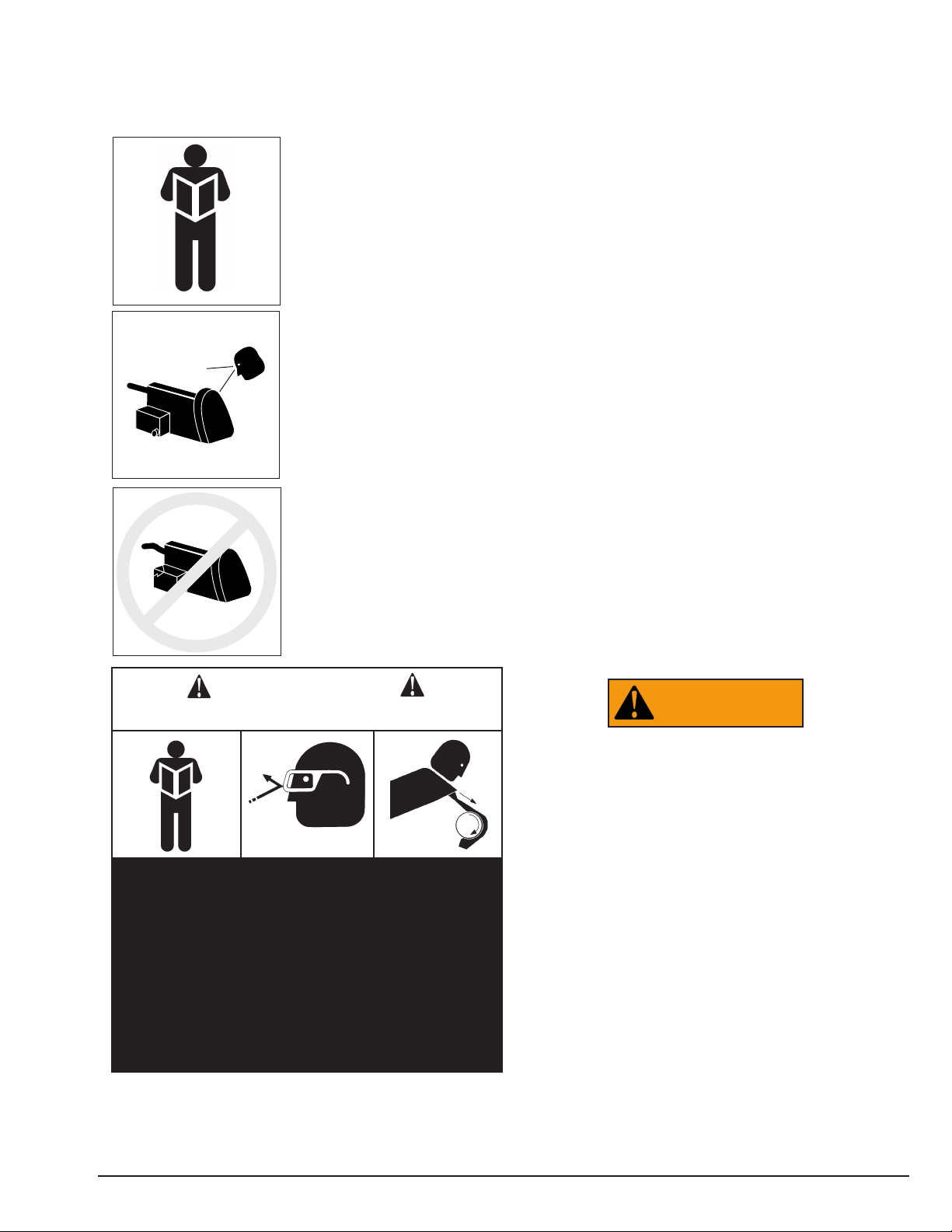
Read entire manual
before installing, operating, or servicing this
equipment.
Proper maintenance
and inspection is necessary for safe operation.
Do not operate a
damaged lathe
This equipment incorporates parts such as snap
switches and power receptacles which tend to produce
arcs or sparks. Therefore, when located in a service
facility, the unit should be in a room or enclosure provided for the purpose, or should be at least 18” or more
above floor to minimize the risk of igniting fuel vapors.
Cautions and Dangers
1. Eye and face protection requirements:
“Protective eye and face equipment is required to
be used where there is a reasonable probability of
injury that can be prevented by use of such
equipment.” OSHA 1910.133 (a).
Protective goggles, safety glasses, or a face shield
must be provided by the purchaser/user and worn
by the operator of the equipment. Make sure all
eye and face safety precautions are followed by
the operator(s). Keep bystanders out of the area.
2. Do not remove any safety equipment, belt guards,
or shortcut controls or operations.
3. Make sure drums and rotors are properly and
squarely mounted before starting lathe, and that all
parts are secure.
4. Do not wear loose clothing, jewelry, or gloves
when operating or working around a lathe.
5. Do not overload the lathe. Read and understand
the lathe specifications. Overloading is poor
machine tool practice, shortens the life of the
lathe, and could cause a failure resulting in
personal injury.
Failure to follow danger, warning, and caution
instructions may lead to serious personal injury or
death to operator or bystander or damage to property. Do not operate this machine until you read and
understand all the dangers, warnings and cautions
in this manual. For additional copies of either, or further information, contact:
Hennessy Industries, Inc.
1601 J.P. Hennessy Drive
LaVergne, TN 37086-3565
(615) 641-7533 or (800) 688-6359
www.ammcoats.com
WARNING
1. Read and follow instructions.
2. Always wear eye protection, avoid loose
clothing and jewelry.
3. Keep all guards, shields, and covers in place and
in working order.
4. Keep bystanders out of work area.
5. Unplug unit from power source before servicing
or adjusting.
6. Maintain unit properly, keep work surfaces and
work area clean.
CAUTION
Prevent accidents and injury,read and follow instructions.
AMMCO Drum & Disc Brake Lathes • 3
Page 6

4 • AMMCO Drum & Disc Brake Lathes
Principal Operating Parts
Know Your Unit
Compare this illustration with the unit before placing it into service. Maximum performance and safety will be
obtained only when all persons using the unit are fully trained in its parts and operation. Each user should learn
the function and location, of all controls.
Prevent accidents and injuries by ensuring the unit is properly installed, operated and maintained.
Control Console
Rotor Rough Cut – press to activate.
Rotor Finish Cut – press to activate.
Rotor Start/Stop – press to start or stop feed.
- (Minus) – press to decrease feed rate value dis-
played.
Feed Rate Display – indicates the value selected for
rough and finish feed rates.
+ (Plus) – – press to increase the feed rate value
displayed.
Spindle Jog – moves the spindle in the direction
indicated. Only active in drum mode.
Drum Rough Cut – press to activate.
Drum Finish Cut – press to activate.
Drum Start/Stop – press to start or stop feed.
4100E Brake Lathe
Control Console
Grease Fitting
Cross Feed Gearbox
Oil Dipstick
Drive Motor Pulley Guard
Drum Feed Gearbox Assembly
Draw Bar
Twin Cutter
Work Light
Spindle Arbor
Spindle Lock Knob
Cross Feed Handwheel
Feed Lever
Cross Feed Lock
Cross Feed Lock Knob
Spindle Speed Adjusting Lever
Power Cord
ON/OFF Switch
Boring Bar and Boring Clamp
8 8
Page 7

AMMCO Drum & Disc Brake Lathes • 5
Do It Now!
Now is a good time
to fill out the Owner’s
Registry Card.
✓
Not Shown
Top View
Front View
Page 8

Basic Operation
To completely understand drum and rotor turning you
must have a knowledge of the lathe itself.
Spindle
The spindle is a motor driven shaft that turns the arbor
upon which the brake drum or rotor is mounted. By
turning the drum and holding a cutting tool against the
inner braking surface, metal can be removed.
Do not move or adjust the spindle speed
lever without the drive motor running.
Damage may occur to the unit.
Spindle Jog
By operating the spindle jog buttons, the spindle will
move to the left or right as desired to position the workpiece. Note that the spindle jog is active only in the
drum mode of operation.
Spindle Feed Rate
Spindle feed rate refers to the amount of movement
the spindle travels per revolution. This feed rate is electronically controlled using +/- buttons on the control
console drum feed adjustments.
Spindle Speed and Adjustment
Spindle speed is measured in RPM (revolutions per
minute) and is adjustable using the 3-position speed
lever at the front of the machine.
Spindle speed adjustment is accomplished by moving
the 3-position speed adjustment lever up or down to
achieve 100, 150, or 200 RPM choices.
Important: Do not adjust the spindle speed unless
the lathe is running.
Cross Feed
The cross feed draws the tool bit across the face of a
brake rotor or flywheel when the cross feed drive is
engaged. The cross feed may also be operated manually using the cross feed handwheel.
Feed speed refers to the rate of movement that the
cutting tools move per revolution of the spindle. The
cross feed speed is variable as indicated on the control
console.
Note: The cross feed has a rough and finish setting.
Both are variable using the control console.
CAUTION
6 • AMMCO Drum & Disc Brake Lathes
Speed and Feed Reference Chart
Refer to the chart on the lathe for typical speed and feed rates. Use this guideline as a starting point and then
fine tune the settings according to your specific application.
Note: These are only suggested speed and feed ranges. Adjust settings as needed to find the optimum setting
for your application.
Workpiece
Diameter (inches)
6 to 9 8 to 15 15 & Up
Spindle RPM 200 150 100
Rough Feed 80 50 30
Finish Feed 16 14 12
Page 9

Cross Feed Handwheel & Feed Lever
Clockwise rotation of the cross feed handwheel
moves the cutting tool in towards the lathe.
Counterclockwise rotation of the cross feed hand-
wheel moves the cutting tool away from the lathe.
Engaging the feed lever completes the feed cycle.
Figure 1 – Rotation of handwheels & Feed Lever
Boring Bar
A boring bar is used to recondition a brake drum.
Clean the slide and bottom of the boring bar clamp.
Install the boring bar and boring bar clamp onto slide,
over the stud bolt and secure with self-aligning nut.
Handtighten the nut only at this point. Make sure the
tool bit is clean and sharp. Replace as necessary to
ensure smooth reconditioning.
Figure 2 - Boring Bar
Twin Cutter
A twin cutter tool is used on to recondition both surfaces of a brake rotor at the same time. The twin cutter
replaces the boring bar on top of the cross feed after
removing the upper and lower tool bar clamps.
1. Mount the twin cutter on the cross feed with the
stud bolt extending through the cast slot. The slot helps
center the twin cutter to the rotor.
2. Secure the twin cutter to the cross feed with self-
aligning nut and washer assembly. Tighten the nut
firmly.
Figure 3 – Install the Twin Cutte
r
AMMCO Drum & Disc Brake Lathes • 7
Cross Feed
Handwheel
Feed Lever
Spindle rotates when
motor is turned on.
Upper and lower
boring bar clamps
Cross slide self-aligning nut/washer
Twin cutter
Cross slide self-aligning nut/washer
Boring Bar Clamp
Page 10

Reconditioning Disc
Brake Rotors
Preparation
1. Inspect the rotor carefully for scoring, rust ridges
(at the inner and outer circumference of the rotor), and
hard spots. Any excessive wear or deformity should be
noted and, if not within acceptable limits, the rotor
should be replaced.
2. Use a micrometer to check the thickness of the
rotor at no less than 3 points around the circumference
about 1” (2.54 mm) in from the outer diameter.
If the rotor thickness varies between readings, it
should be reconditioned. However, if the thickness is
less than the minimum established by the manufacturer, or if it will be less after reconditioning, the rotor
should be replaced.
Note: Most often
the DISCARD thickness dimension is
cast or stamped into
the rotor, not the
minimum machineto thickness.
Figure 4 – Measure Rotor Thickness
Model 6950 Twin Cutter
The 6950 twin cutter mounts on the cross feed tool
post to resurface both rotor surfaces simultaneously.
Each tool bar is individually adjustable (in thousandths
of an inch or millimeters) to permit precise depth-of-cut
settings.
The tool bars mount on top of the tool bar support,
carbide tips up, and are used to recondition both brake
surfaces of a rotor at the same time.
Figure 5 – 6950 Twin Cutter Controls
Installation
1. Remove the self-aligning nut/washer assembly
retaining the boring bar clamp.
2. Remove the clamp and boring bar.
Note: Older lathes have a tool post pivot screw which
must be loosened before the lower clamp can be
removed.
3. Place the tool bar support over the cross feed tool
post stud and replace self-aligning nut/washer assembly.
4. Align the tool bar support parallel with the arbor
and wrench tighten the nut.
Preparation
1. Inspect the rotor carefully for scoring, rust ridges
(at the inner and outer circumference of the rotor), and
hard spots. Any excessive wear or deformity should be
noted and, if not within acceptable limits, the rotor
should be replaced.
2. Use a micrometer to check the thickness of the
rotor at no less than 3 points around the circumference
about 1” (2.54 mm) in from the outer diameter.
If the rotor thickness varies between readings, it
should be reconditioned. However, if the thickness is
less than the minimum established by the manufacturer, or if it will be less after reconditioning, the rotor
should be replaced.
Note: Most often the DISCARD thickness dimension
is cast or stamped into the rotor, not the minimum
machine-to thickness.
Inch/Millimeter
Micrometer Dials
Adjustment Knobs
8 • AMMCO Drum & Disc Brake Lathes
Page 11
AMMCO Drum & Disc Brake Lathes • 9
Rotor Mounting
Review the descriptions of mounting drums on page
13. The same directions apply when mounting a brake
rotor. Hubbed rotors are mounted on adapters that fit
into the bearing races. Hubless rotors use a cone in the
center hole and a hubless adapter on each side of the
rotor. Spacers are used to fill out the arbor shaft so that
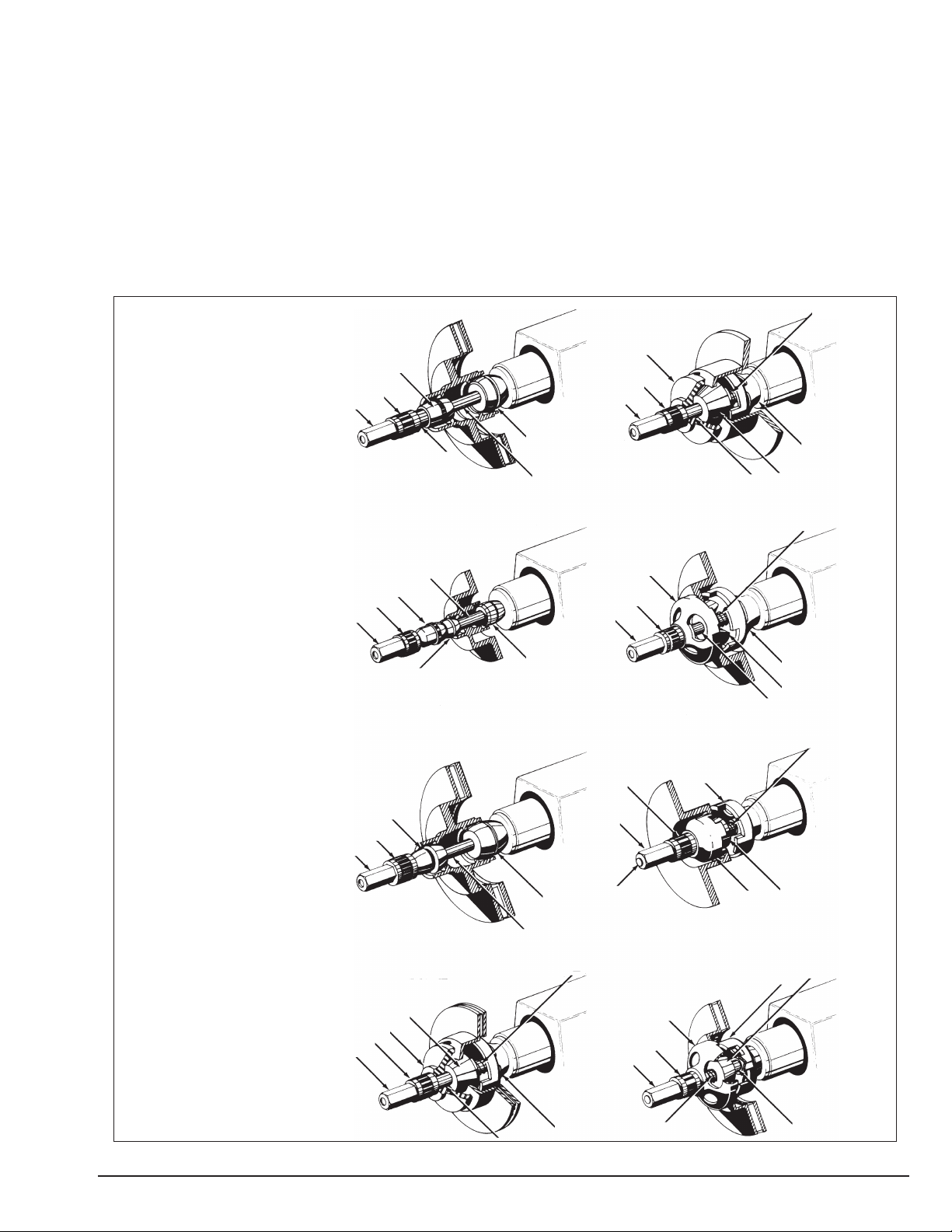
the arbor nut can be tightened. The setups illustrated
below are typical of the many mounting configurations
necessary to meet the requirements of brake rotor
reconditioning. The adapters, cones, and spacers sup-
plied with the lathe will allow reconditioning of the
majority of the rotors found on current production vehicles. Optional adapters, cones, and spacers are available to meet special needs.
Note: Adapters may also be used as spacers to fill out
the arbor shaft if care is taken to prevent damage to
their machined surfaces.
The patented self-aligning spacer prevents diagonal
thrust on t he adapters. The self-aligning spacer should
always be used adjacent to the arbor nut.
- 1” Arbor
- Arbor Nut
- Self-Aligning Spacer
- Spacer
- Spring
- Small Hubless Adapter
- Large Hubless Adapter
- Centering Cone
- Small Double Taper Adapter
- Large Double Taper Adapter
- Adapter, Used as Spacer
Page 12

10 • AMMCO Drum & Disc Brake Lathes
Double Chuck Adapter
Mounting drums or rotors using the Ammco double
chuck adapter.
Figure 6 – Double Chuck Adapter
1. Thoroughly clean the surface of the rotor or drum
that will be mounted on the double chuck.
2. Place the hubless rotor or drum on a flat clean sur-
face. Install the double chuck by positioning the appropriate jaws in the center hole. Tighten the jaws by
inserting the key into one of the key slots in the side of
the chuck turning counterclockwise. The double chuck
will automatically self center the rotor or drum.
Note: Make sure that the chuck jaws are tight.
Do not leave the key in the key slot when
starting the brake lathe.
3. Install the backing plate onto the brake lathe arbor
with offset facing outward.
4. Install the double chuck, with rotor or drum
installed, onto the 1-inch arbor. Use the spacers supplied with the brake lathe so that it extends out to the
arbor threads.
5. Use the arbor nut supplied with the machine and
tighten the nut against the spacers.
6. After tightening the double chuck, turn on the
brake lathe to check for runout of the rotor or brake
drum. Machine the rotor or drum.
Note: Always use the backing plate to help eliminate
rotor or drum vibration during turning. If necessary, use
a small spacer before the installation of the backing
plate.
Set Up and Reconditioning Rotors
1. Install a silencer band on the mounted rotor.
Stretch the band around the rotor and hook the metal
loop over a lead weight.
Figure 7 – Attach Silencer Band
2. Center the twin cutter to the rotor. Loosen the
stud nut and adjust the twin cutter so that the rotor is
centered between the tool bits. The slot of the twin cutter should be approximately parallel to the lathe spindle. Tighten the stud nut firmly.
Figure 8 – Center the Twin Cutter
CAUTION
Silencer band
Twin cutter
Stud nut
Tool bits
Page 13

AMMCO Drum & Disc Brake Lathes • 11
3. Install the safety shield. Review the cautions and
dangers section and the general safety information at
the beginning of this manual. The safety shield is easily
screwed onto the twin cutter in the threaded mounting
hole provided.
Always wear safety glasses or a face shield. Cutting
or grinding on an exposed surface such as a rotor
will produce flying chips and debris.
Figure 9 – Attach the Safety Shield
4. Adjust the spindle speed to match the rotor size.
Use the faster speeds for passenger car and most light
duty truck rotors. Choose lower speeds when machining medium duty and larger truck rotors and some solid
rotors. (Refer to the “Speed and Feed Reference
Chart” located on front of the lathe for suggested settings.)
Figure 10 – Adjust Spindle Speed
5. Make sure that the tool bits clear the rotor sur-
faces and the silencer band. Give the rotor a full turn by
hand and watch for clearance all the way around.
6. Turn the lathe ON.
7. Turn each tool bit control (the outer knurled knobs)
clockwise until the tool bits just contact the rotor surfaces.
8. When the tool bits make contact, rotate each of
the inner depth-of-cut collars to zero and back the tool
bits away from the rotor.
From this point on, all tool adjustments will be made
with the tool bit controls. Then inner depth-of-cut collars will be the reference and should not be moved.
Figure 11 – Tool bit controls
9. Turn the cross feed handwheel until the tool bits
are at mid-point of the rotor face.
10. Turn the left hand tool bit control until the tool bit
contacts the rotor surface and makes a scratch cut.
After the cut is made, back the tool bits off and turn the
lathe OFF.
Figure 12 – First scratch cut
The scratch will usually appear as an incomplete circle. This is caused by runout or wobble due to rotor condition, or by the way the rotor is mounted on the arbor.
WARNING
Safety shield
Twin cutter
Spindle Speed 3-position
Adjustment Lever
Inner depth-ofcut collars
Tool bit controls
Hold knob with one hand
– turn collar
Each increment =
0.002” english,
0.05 mm metric
First scratch cut
Page 14

12 • AMMCO Drum & Disc Brake Lathes
11. If you see excessive runout on the rotor:
A. Check rotor mounting by loosening the arbor
nut and turning the rotor 180° by hand on the
arbor. Make sure the inside adapter does not
rotate along with the rotor. Then retighten the
arbor nut, turn the cross feed handwheel back 1/2
turn, turn the lathe ON, and repeat step 10 to
make a second scratch cut.
Figure 13 – Rotate rotor 180°
Figure 14 – Second scratch cut
B. If the scratch cuts are side-by-side, the runout or
wobble is caused by rotor condition. A dial
indicator may be used to compare rotor runout
with manufacturer’s specifications.
Figure 15 – Using a dial indicator
C. If the scratch cuts are opposite one another
(180°), the rotor may not be properly mounted on
the arbor. Remove the rotor and examine the arbor
and all adapters for nicks, burrs, chips, dirt, or rust.
Inspect the rotor hub for loose or damaged
bearing cups. Clean, repair, remount, or replace as
necessary.
D. Recheck setting of the depth-of-cut collars which
were set to zero earlier by moving the tool bits
inward until they just contact the surfaces of the
rotor. The collars should be at zero. Reset the collars
if necessary.
12. Turn the cross feed handwheel clockwise until
the tool bits are near the rotor hub.
13. Turn the lathe ON.
14. Turn both tool bit controls to the desired depth-
of-cut and lock them in position by tightening the red
lock knobs above the tool bits.
Note: Either rough or finish cuts may be taken to
resurface a rotor. Generally, finish cuts should be
0.004” (0.10 mm) to 0.006” (0.15 mm) per side. Very
shallow cuts of less than 0.004” (0.10 mm) per side
tend to reduce tool bit life because the heat generated
during reconditioning isn’t transferred to the rotor efficiently. Rough cuts may be taken from 0.006” (0.15
mm) to 0.010” (0.25 mm) per side.
15. Press the rotor start button on the control con-
sole and then engage the feed lever that is located on
the right side of the cross feed handwheel.
Note: The rotor feed rate may be changed by pressing
either the + or - button on the control console.
16. When the lathe has finished machining the rotor.
Turn the lathe off and loosen the cutting engagements.
Rotate rotor only 180°
Loosen arbor
nut, do not turn
inside adapter
Second
scratch cut
Scratch cuts
opposite each
other
Dial indicator
Page 15

AMMCO Drum & Disc Brake Lathes • 13
Reconditioning Brake
Drums
Preparation
1. Measure the diameter of the brake drum with a
brake drum micrometer.
Figure 16 – Measure drum diameter
2. Determine if the drum will be within maximum
rebore limits after reconditioning.
Note: Most often, the DISCARD diameter is cast into
the brake drum, not the maximum machining diameter.
3. Inspect brake drum. Do not attempt to machine a
drum that is damaged or in poor condition.
Mounting Drums
1. Loosen the boring bar clamp nut and push the bor-
ing bar all the way into the clamp.
2. Mount the drum on the arbor using the proper
adapters, cones, and spacers. Use examples in Figure
18 for guidance.
3. Wrap the drum silencer band snugly around the
drum. Be sure it covers up to the right-hand edge.
Figure 17 – Attach silencer band
4. Position the cross slide by turning the cross feed
handwheel to its maximum clockwise (in) position. Then
back off the cross feed handwheel 2 complete turns .
Figure 18 - Mounting the Drum
Note: Also refer to the Double Chuck Adapter section
(page 10) when mounting drums or rotors using the
Ammco®double chuck.
Hubbed Brake Drums
A
C
B
L
K
D
F
Tapered cone adapters fit in the bearing seats, making con-
tact near the middle of the bearing race whenever possible
rather than near an edge. Various adapters and spacers may
be used to fill out the shaft of the arbor.
Hubless Brake Drums
A
C
B
E
H
D
F
A cone fits into the center hole of the drum from the inside
to center the drum on the arbor. Select a hubless adapter
which will fit inside the drum, against the flat lug hole sur-
face and either straddle the bolt holes to avoid mounting
against a burr, or remove the burrs. Slip the hubless
adapter onto the arbor followed by a spring, the cone, the
drum, and another hubless adapter. Fill out the shaft with
spacers as needed.
J
I
G
Key to Mounting Adapters, Cones, and Related Parts
A. 1” Arbor G. Spring
B. Arbor Nut H. Inside Floating Adapter (sm.)
C. Self-Aligning Spacer I. Outside Floating Adapter (lg.)
D. Lathe Spindle Nose J. Centering Cone
E. Spacer K. Large Double Taper Adapter
F. Protective Boot L. Small Double Taper Adapter
Note: The self-aligning spacer should always be used next
to the arbor nut when tightening. To avoid overtightening,
wrench tighten the arbor nut counterclockwise until the
drum and adapters begin to turn on the arbor, then continue
to advance the wrench
1
⁄16 of a turn. DO NOT overtighten
the arbor nut.
Arrows for reading scale
Dial
Buckle Finger
Silencer Band for Drums
Page 16

14 • AMMCO Drum & Disc Brake Lathes
5. Position the boring bar by loosening the boring bar
clamp nut and sliding the boring bar inward toward the
drum until the tool bit is close to the drum.
The boring bar position is changed whenever a drum
of different diameter is machined.
The entire boring bar clamp may also be swiveled to
achieve the best cutting position.
Figure 19 – Positioning the boring bar
6. Turn the drum by hand to make sure that every-
thing is clear.
7. Turn the lathe ON.
8. Advance the tool bit using the cross feed hand-
wheel until it just contacts the drum surface momentarily and makes a scratch cut.
Figure 20 – First scratch cut
9. Loosen the dial lock screw on the cross feed hand-
wheel and set the dial to the diameter of the drum as
measured with the micrometer. Tighten the lock screw.
This setting will be the reference used to help deter-
mine the drum recondition diameter.
Figure 21 – Set drum diameter measurement
10. Back the tool bit off and turn the lathe OFF.
11. Loosen the arbor nut, rotate the drum 1⁄2 turn
(180°) on the arbor and inner adapter, and retighten the
nut.
12. Turn the lathe ON.
13. Turn the workpiece on the spindle 1⁄2 turn in
either direction and make a second scratch cut.
Figure 22 – Second scratch cut
14. Turn the lathe OFF.
15. Examine the scratch cuts.
If the first and second cuts are opposite one another
(180° apart), remove the drum from the arbor, check the
mounting adapters and arbor for nicks, burrs, or chips,
remount the drum, and repeat scratch cut process.
If the scratches are side by side, proceed to step 16.
16. Turn the lathe on and use spindle jog button to
position the tool bit until the deepest worn groove of
the drum lines up with the point of the tool bit.
First
Scratch Cut
Dial Lock
Screw
Second
Scratch Cut
Page 17

AMMCO Drum & Disc Brake Lathes • 15
17. Advance the tool bit into the bottom of the
groove by rotating the cross feed handwheel counterclockwise.
Note: These operations may be done with the lathe
running.
The depth of cut dial will show the approximate reconditioned diameter of the drum. This measurement must
be compared with:
A. The maximum rebore limits cast into the drum.
B. The measured diameter to determine the best
amount of material to be removed in one pass.
18. Determine the depth-of-cut by these general
guidelines:
• Roughing cuts should be no deeper than 0.020”
(0.50mm).
• Finish cuts should be no shallower than 0.004” (0.10
mm) deep.
19. With the lathe running, set the depth-of-cut dial
to the depth desired and lock the cross feed by tightening the lock knob.
Figure 23 – Lock cross feed
20. At the control console, select to activate either
the drum rough cut or drum finish cut button. The drum
feed rate may be changed by pressing either + or - button on the control console.
21. Set the feed shut-off by sliding it on the shaft to
a point that approximately equals the depth of the drum
and tightening it in place. The feed will stop when it
reaches this point.
Figure 24 – Set spindle feed shut-off
22. Press the drum start button to begin.
Spindle
Lock Knob
Shut-off
Collar
Cross Feed
Lock Knob
Page 18

16 • AMMCO Drum & Disc Brake Lathes
Maintenance and
Service
Oiling
The lathe is shipped from the factory with the correct
amount and type of oil. Check oil level frequently, and
refill as necessary with EP-80-90 gear oil.
Figure 25 – Oiling
After every 500 hours of use, drain the oil and refill to
the appropriate level on the dipstick with clean EP-8090 gear oil. Use the oil drain plug on the front of the
lathe to drain the old oil.
Figure 26 – Drain plug location
The variable feed gearbox and the disc brake feed
mechanism assemblies do not require lubricant.
Lubricate the cross feed once each month with an
automotive chassis grease. Pump the grease into the
fitting until clean grease comes out the relief slot at the
base of the fitting.
Use a hand pump grease gun only. A high pressure
gun can burst the lathe casting.
Figure 27 – Cross feed grease fitting
Grease the lead screw drive monthly. Locate the lead screw
drive by pulling the protective boot back.
Figure 28 – Lead screw drive
Oil exposed metal parts periodically to prevent rust.
Cleaning
Keep the lathe as clean as possible for trouble-free
operation, as well as safety and longer lathe life. Use a
brush to sweep metal chips and dust off the lathe.
Do not use compressed air to blow the lathe clean.
Chips and dust may be driven between machined parts
and into bearings, causing undue wear.
Care of Arbors and Adapters
Although the adapters, arbors, and spindle are made
of top grade steel and are turned, hardened, and precision ground to close tolerances, great care should be
taken in their use, handling, and storage. Even the
smallest nick, scratch, or loose chip can cause incorrect
rotor or drum alignment, resulting in inaccurate reconditioning.
Remove all adapters from the arbor after reconditioning a drum or rotor and wipe them clean – especially
the inboard adapter. When a finished drum or rotor is
removed from the arbor, the inboard adapter may move
slightly away from the face of the arbor and allow metal
chips to fall into the opening, causing a poor mounting
for the next drum or rotor.
Regularly inspect the faces and seating tapers of the
adapters for nicks and scratches, correct any flaw with
a fine stone. If the damage cannot be corrected,
replace the adapter. Handle the adapters and arbors
with care and store them on individual hooks. Do not
throw them into a box. The adapters are designed for
mounting drums and rotors only. Do not misuse the
adapters.
Grease fitting
for cross feed
Dipstick
Oil level
Oil drain plug
Relief slot
Feed mechanism lead screw
Page 19

AMMCO Drum & Disc Brake Lathes • 17
Installation Instructions
Receiving
The shipment should be thoroughly inspected as soon
as it is received. The signed bill of lading is acknowledgement by the carrier of receipt in good condition of
shipment covered by our invoice.
If any of the goods called for on this bill of lading are
shorted or damaged, do not accept them until the carrier makes a notation on the freight bill of the shorted
or damaged goods. Do this for your own protection.
NOTIFY THE CARRIER AT ONCE if any hidden loss or
damage is discovered after receipt and request the carrier to make an inspection. If the carrier will not do so,
prepare a signed statement to the effect that you have
notified the carrier (on a specific date) and that the carrier has failed to comply with your request.
IT IS DIFFICULT TO COLLECT FOR LOSS OR DAMAGE AFTER YOU HAVE GIVEN THE CARRIER A CLEAR
RECEIPT.
File your claim with the carrier promptly. Support your
claim with copies of the bill of lading, freight bill,
invoice, and photographs, if available.
Although AMMCO’s responsibility ceases upon delivery of the shipment to the carrier, we will gladly assist
in tracing lost shipments. Our willingness to assist in
every possible manner does not make AMMCO
responsible for collection of claims or replacement of
lost or damaged materials. Shipping damage claims will
not be handled under warranty.
Electrical Requirements
The lathe must be properly grounded to protect the
operator from shock. The lathe is equipped with an
approved 3-conductor cord and a 3-prong grounding
type plug to fit the proper grounding-type receptacle.
Should an extension cord be required, use 3-conductor
cords with 3-prong grounding plug and 3-prong grounding receptacle properly rated to handle this electrical
power tool only. Do not modify a cord or plug to match
a receptacle; have a qualified electrician install an
appropriate outlet to match the lathe requirements.
Repair or replace any worn or damaged power cords
immediately.
Verify that the lathe plug and grounding-type receptacle match as shown in Figure 29.
Figure 29 - Power Cord Plug and Receptacle Types
Setup
A factory trained COATS®Service Technician must perform the install, setup, and initial test procedures on
your brake lathe. Do not attempt to install and setup the
unit yourself. Accurate and reliable operation of your
unit depends on proper installation. Please contact
COATS®directly at 1-800-688-9240 for the Certified
Service Partner nearest you.
Connect to Power
Your factory trained COATS®Service Technician should
do the final check to verify the power installation before
connecting the brake lathe to a power supply. Failure
due to improper power connection may void the war-
ranty.
Operating Specifications
• Overall Lathe Height . . . . . . . . . . .17.25" [438 mm]
• Lathe Shipping Weight . . . . . . . . . .410 lbs [186 kg]
• Floor Space Requirements:
Width . . . . . . . . . . . . . . . . .48" [1219.20 mm]
Deep . . . . . . . . . . . . . . . . . .34.5" [901.70 mm]
Spindle to Floor . . . . . . . .39.375" [1000 mm]
(mounted to optional bench)
• Electrical Requirements
(unless otherwise specified)
:
Standard: 115 VAC, 60 Hz, single-phase, fused
at 20 amps
Optional: 220 VAC, 60 Hz, single-phase, fused
at 15 amps
• Spindle Motor . . . . . . . . .1 HP, 60 Hz, 115/230 VAC
• Spindle Travel . . . . . . . . . . . . . . . .9.875" [251 mm]
• Spindle Speed Lever Positions:
Lower Groove . . . . . . . . . . . . . . . . . . . . . .100
Middle Groove . . . . . . . . . . . . . . . . . . . . .150
Upper Groove . . . . . . . . . . . . . . . . . . . . . .200
• Spindle Feed Speeds . . . . . . . . . . . . . . . . .Variable
• Cross Feed Speed . . . . . . . . . . . . . . . . . . .Variable
• Handwheel Graduations . . . . . . .0.002 [0.050 mm]
• Maximum Brake Rotor:
Diameter . . . . . . . . . . . . . . . . .15" [381.0 mm]
Thickness . . . . . . . . . . . . . . . .1.9" [48.26 mm]
• Brake Drum Diameter:
Minimum . . . . . . . . . . . . . . . . . . .6" [152 mm]
Maximum . . . . . . . . . . . . . . . . . .28" [711 mm]
• Maximum Drum Depth . . . . . . . .9.875" [251 mm]
• Maximum Load:
1" Arbor . . . . . . . . . . . . . . . .200 lbs [90.72 kg]
1.875" Arbor . . . . . . . . . . . .200 lbs [90.72 kg]
Page 20

95000103 01 04/08 © Copyright 2007 Hennessy Industries and AMMCO All Rights Reserved Printed in USA
 Loading...