

Page 1
1601 J. P. Hennessy Drive, LaVergne, TN USA 37086-3565 615/641-7533 800/688-6359 Manual Part No.: 929250 09
HENNESSY INDUSTRIES INC. Manufacturer of AMMCO
®
, COATS®and BADA®Automotive Service Equipment and Tools. Revision: 05/01
3850, 3860
Drum & Disc
Brake Lathes
®
Installation Instructions
Operating Instructions
Safety Instructions
Maintenance Instructions
READ these instructions before placing unit in
service. KEEP these and other materials delivered
with the unit in a binder near the machine for
ease of reference by supervisors and operators.
Page 2

ii • AMMCO 3850, 3860 Brake Lathes
Brake Lathes
Page 3

AMMCO 3850, 3860 Brake Lathes • iii
Table of Contents
Safety Notices and Decals . . . . . . . . . . . . .iv
Warning . . . . . . . . . . . . . . . . . . . . . . . . . . . .iv
Cautions and Dangers . . . . . . . . . . . . . . . . . . . .iv
Owner’s Responsibility . . . . . . . . . . . . . . . .v
Definitions of Hazard Levels . . . . . . . . . . . .v
Important Safety Instructions . . . . . . . . . .vi
Before You Begin
Receiving . . . . . . . . . . . . . . . . . . . . . . . . . . . . . .1
Electrical Requirements . . . . . . . . . . . . . . . . . . . .1
Installation . . . . . . . . . . . . . . . . . . . . . . . . . . . . .2
Preparation for Use . . . . . . . . . . . . . . . . . . . . . . .2
Specifications . . . . . . . . . . . . . . . . . . . . . . . . . . .2
Principle Operating Parts . . . . . . . . . . . . . . . . . . .3
Operating Instructions
Negative and Positive Rake Tooling . . . . . . . . . . .3
Starting the Lathe . . . . . . . . . . . . . . . . . . . . . . . .4
Selecting Feed Drive Direction - Rotor or Drum . .4
Reading the Drum Depth-of-Cut Micrometer Dial . .5
Arbor Installation . . . . . . . . . . . . . . . . . . . . . . . . .5
Mounting Drums . . . . . . . . . . . . . . . . . . . . . . . . .6
Reconditioning Brake Drums . . . . . . . . . . . . . . . .6
Mounting Brake Rotors . . . . . . . . . . . . . . . . . . .10
Reconditioning Brake Rotors . . . . . . . . . . . . . . .11
Maintenance and Service . . . . . . . . . . . . .14
Lubrication . . . . . . . . . . . . . . . . . . . . . . . . . . . .14
Cleaning . . . . . . . . . . . . . . . . . . . . . . . . . . . . . .15
Arbor and Adapter Care . . . . . . . . . . . . . . . . . . .15
Gib Adjustment . . . . . . . . . . . . . . . . . . . . . . . . .16
3860 Drum Tool Bar Adjustment . . . . . . . . . . . .17
Contents
Page 4
iv • AMMCO 3850, 3860 Brake Lathes
Safety
Safety Notices and
Decals
For your safety, and the safety of others, read and
understand all of the safety notices and decals included here and on the unit.
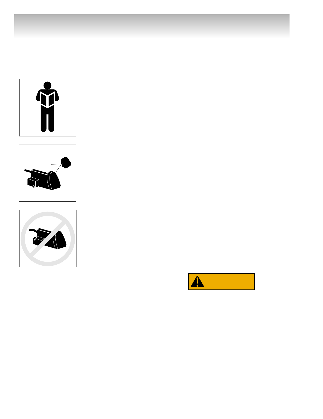
Read entire manual
before installing,
operating, or servicing this equipment.
Proper maintenance
and inspection is
necessary for safe
operation.
Do not operate a
damaged lathe.
Warning
This equipment incorporates parts such as snap
switches and power receptacles which tend to produce arcs or sparks. Therefore, when located in a service facility, the unit should be in a room or enclosure
provided for the purpose, or should be at least 18” or
more above floor to minimize the risk of igniting fuel
vapors.
Cautions and Dangers
1. Eye and face protection requirements:
“Protective eye and face equipment is required
to be used where there is a reasonable
probability of injury that can be prevented by use
of such equipment.” OSHA 1910.133 (a).
Protective goggles, safety glasses, or a face
shield must be provided by the purchaser/user
and worn by the operator of the equipment.
Make sure all eye and face safety precautions are
followed by the operator(s). Keep bystanders out
of the area.
2. Do not remove any safety equipment, belt
guards, or shortcut controls or operations.
3. Make sure drums and rotors are properly and
squarely mounted before starting lathe, and that
all parts are secure.
4. Do not wear loose clothing, jewelry, or gloves
when operating or working around a lathe.
5. Do not overload the lathe. Read and understand
the lathe specifications. Overloading is poor
machine tool practice, shortens the life of the
lathe, and could cause a failure resulting in
personal injury.
Failure to follow danger, warning, and caution
instructions may lead to serious personal injury or
death to operator or bystander or damage to property. Do not operate this machine until you read
and understand all the dangers, warnings and cautions in this manual. For additional copies of either,
or further information, contact:
Hennessy Industries, Inc.
1601 J.P. Hennessy Drive
LaVergne, TN 37086-3565
(615) 641-7533 or (800) 688-6359
www.Hennessy-Ind.com
WARNING
Page 5
AMMCO 3850, 3860 Brake Lathes • v
Owner’s Responsibility
To maintain machine and user safety, the responsibility of the owner is to read and follow these instructions:
• Follow all installation instructions.
• Make sure installation conforms to all applicable
Local, State, and Federal Codes, Rules, and
Regulations; such as State and Federal OSHA
Regulations and Electrical Codes.
• Carefully check the unit for correct initial function.
• Read and follow the safety instructions. Keep
them readily available for machine operators.
• Make certain all operators are properly trained,
know how to safely and correctly operate the
unit, and are properly supervised.
• Allow unit operation only with all parts in place
and operating safely.
• Carefully inspect the unit on a regular basis and
perform all maintenance as required.
• Service and maintain the unit only with
authorized or approved replacement parts.
• Keep all instructions permanently with the unit
and all decals/labels/notices on the unit clean and
visible.
• Do not override safety features.
Definitions of Hazard
Levels
Identify the hazard levels used in this manual with
the following definitions and signal words:
DANGER
Watch for this symbol:
It Means: Immediate hazards, which will result in
severe personal injury or death.
WARNING
Watch for this symbol:
It Means: Hazards or unsafe practices, which could
result in severe personal injury or death.
CAUTION
Watch for this symbol:
It Means: Hazards or unsafe practices, which may
result in minor personal injury or product or property
damage.
Watch for this symbol! It means BE ALERT! Your
safety, or the safety of others, is involved!
Safety
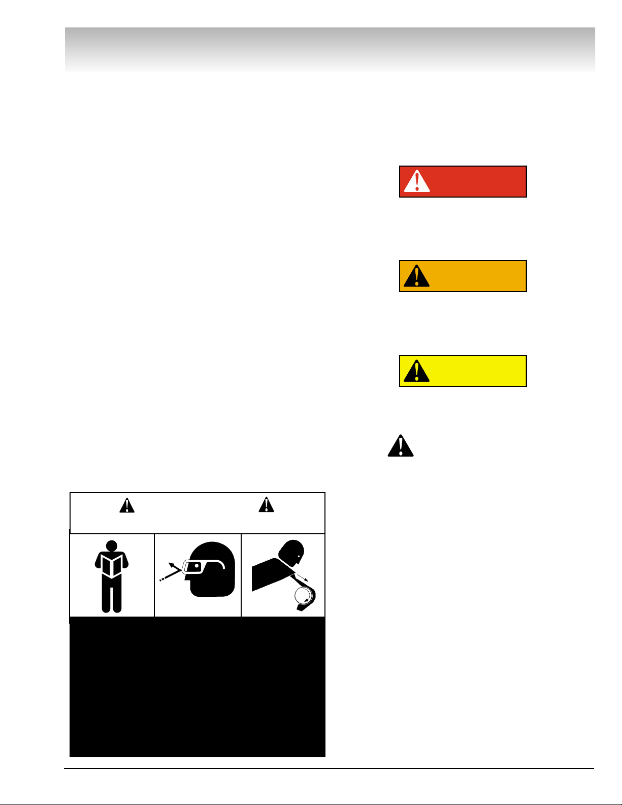
1. Read and follow instructions.
2. Always wear eye protection, avoid loose
clothing and jewelry.
3. Keep all guards, shields, and covers in place and
in working order.
4. Keep bystanders out of work area.
5. Unplug unit from power source before servicing
or adjusting.
6. Maintain unit properly, keep work surfaces and
work area clean.
CAUTION
Prevent accidents and injury, read and follow instructions.
DANGER
WARNING
CAUTION
Page 6

vi • AMMCO 3850, 3860 Brake Lathes
READ ALL INSTRUCTIONS
When using your garage equipment, basic safety precau-
tions should always be followed, including the following:
1. Keep guards in place and in working order.
2. Remove adjusting keys and wrenches from the tool
before turning it on. Make this a habit.
3. Keep work area clean and well lighted. Cluttered areas
and benches invite accidents.
4.To reduce the risk of fire, do not operate equipment in the
vicinity of open containers of flammable liquids (gasoline).
5. Adequate ventilation should be provided when working
on operating internal combustion engines.
6. Care must be taken as burns can occur from touching
hot parts.
7. Do not operate equipment with a damaged cord or if the
equipment has been dropped or damaged—until it has been
examined by a qualified serviceman.
8. If an extension cord is necessary, a cord with a current
rating equal to or more than that of the equipment should be
used. Cords rated for less current than the equipment may
overheat. Care should be taken to arrange the cord so that it
will not be tripped over or pulled.
9. To reduce the risk of electric shock, do not use on wet
surfaces or expose to rain.
10. Keep children away. All bystanders should be kept com-
pletely away from the work area.
11. Make the workshop kid-proof. Use padlocks and mas-
ter switches, and remove starter keys.
12. Don’t force a tool. It will do the job better and safer at
the rate for which it was designed.
13. Use the right tool. Don’t force a tool or an attachment
to do a job for which it was not designed.
14. Dress properly. Keep hair, loose clothing, neckties,
shop rags, jewelry, fingers, and all parts of body away from
moving parts. Non-slip footwear is recommended.
15. ALWAYS WEAR SAFETY GLASSES. Everyday eye-
glasses only have impact resistant lenses, they are NOT
safety glasses. Safety glasses, goggles, or a face shield will
help protect the operator from injury. Use a face shield and
dust mask during dusty operations.
16. Secure the work properly to the unit for setup and tool
bit positioning. Do not attempt to hold a drum or rotor steady
on the arbor with your hands. Both hands must be free to
operate unit.
17. Don’t overreach. Keep proper footing and balance at all
times when lathe is in operation or when working around the
unit.
18. Maintain tools with care. Keep tools sharp and clean for
best and safest performance. Follow instructions for lubricating and changing accessories.
19. Remove power from the unit and disconnect tools
before servicing and when changing accessories such as
blades, bits, cutters, etc. Follow lock-out and tag-out procedures as required.
20. Avoid unintentional starting. Make sure the switch is in
the OFF (O) position before plugging the machine in or performing any maintenance or service work.
21. Use of improper accessories may cause risk of injury to
operator or bystanders. Use only as described in this manual.
Use only manufacturer’s recommended attachments.
22. Never stand or lean on a lathe. Serious injury could
occur if the lathe is tipped or if the cutting tool is unintentionally contacted.
23. Check damaged parts carefully. Before further use of
the lathe, a guard or other part that is damaged should be
carefully checked. Immediately replace all damaged, missing,
or non-functional parts. Check for alignment of moving parts,
binding of moving parts, breakage of parts, mounting, and any
other conditions that may affect operation. Guards and other
parts that are damaged should be properly repaired or
replaced before lathe is used again.
24. Always feed the work into a blade or cutter and against
the direction of rotation. Cutters and tool bits are designed to
cut from the inside of a drum or rotor to the outer edge. Do
not attempt to cut from the outside edge in to the center.
25. Never leave tools running unattended. Turn the power
off. Don’t leave the tool until it comes to a complete stop.
26. Never use compressed air to blow the tool clean. Chips
and dust may be driven between machined parts and into
bearings, causing undue wear. They may also contact persons
in the area causing personal injury.
27. Operate the lathe in the proper environment. The lathe
incorporates parts such as snap switches and power receptacles which tend to produce arcs or sparks. Therefore, when
located in a garage,the unit should be in a room or enclosure
provided for the purpose, or should be at least 18” or more
above the floor to minimize the risk of igniting fuel vapors.
Before operating the lathe, review the warning information on the lathe and the cautions, warnings and dangers in this manual. Also review the following general safety instructions. Failure to follow safety instructions could result in personal injury to
operator or bystanders and damage to the lathe or personal property.
IMPORTANT SAFETY INSTRUCTIONS
SAVE THESE INSTRUCTIONS
Page 7

Brake Lathes
AMMCO 3850, 3860 Brake Lathes • 1
Before You Begin
Receiving
The shipment should be thoroughly inspected as soon as it is
received. The signed bill of lading is acknowledgement by the
carrier of receipt in good condition of shipment covered by our
invoice.
If any of the goods called for on this bill of lading are shorted
or damaged, do not accept them until the carrier makes a notation on the freight bill of the shorted or damaged goods. Do this
for your own protection.
NOTIFY THE CARRIER AT ONCE if any hidden loss or damage
is discovered after receipt and request the carrier to make an
inspection. If the carrier will not do so, prepare a signed statement to the effect that you have notified the carrier (on a specific date) and that the carrier has failed to comply with your
request.
IT IS DIFFICULT TO COLLECT FOR LOSS OR DAMAGE AFTER
YOU HAVE GIVEN THE CARRIER A CLEAR RECEIPT.
File your claim with the carrier promptly. Support your claim
with copies of the bill of lading, freight bill, invoice, and photographs, if available.
Although AMMCO's responsibility ceases upon delivery of the
shipment to the carrier, we will gladly assist in tracing lost shipments. Our willingness to assist in every possible manner does
not make AMMCO responsible for collection of claims or
replacement of lost or damaged materials. Shipping damage
claims will not be handled under warranty.
Electrical Requirements
The lathe must be properly grounded to protect the operator
from shock. The lathe is equipped with an approved 3-conductor
cord and a 3-prong grounding type plug to fit the proper grounding-type receptacle. Should an extension cord be required, use
3-conductor cords with 3-prong grounding plug and 3-prong
grounding receptacle properly rated to handle this electrical
power tool only. Do not modify a cord or plug to match a receptacle; have a qualified electrician install an appropriate outlet to
match the lathe requirements. Repair or replace any worn or
damaged power cords immediately.
The lathe requires a single-phase power source of 115 VAC
(±10%), 60 Hz, fused at 15 A for proper operation.
Figure 1 - Power Cord Plug and Receptacle
Page 8

Installation
1. Assemble bench according to the instructions provided.
Tighten all fasteners securely.
2. After assembly, the bench should be leveled and bolted
down with 3/8 or 7/16 inch bolts or lag screws.
3. Unbolt the lathe from the shipping pallet. Lift the lathe onto
the bench using the eye bolt located on top of the lathe. Do not
lift the lathe by the motor, pulley cover, crossfeed endcap, or
leadscrew protective tube on the rear of the unit.
4. Bolt the lathe to the bench with the hardware provided.
Tighten fasteners securely.
5. Remove any packing materials and protective wrapping
from the lathe and components.
6. Make sure lathe is turned off (switch in "O" position). Plug
lathe into a properly installed and grounded outlet that matches
the lathe plug.
7. Clear the area and turn lathe on. Check for proper operation
(motor and spindle rotation).
Preparation for Use
1. Inspect all adapters and accessories for burrs, nicks, or
other damage.
2. Clean accessories with a vaporizing solvent.
3. Apply a light film of oil to all adapters to protect their
machined surfaces from rust. Refer to the maintenance section
for more information.
Specifications
Overall Lathe Height . . . . . . . . . . . . . . . . . . . . . . . . . . .16.5 in
Spindle to Floor (on AMMCO bench) . . . . . . . . . . . .39.625 in
Spindle Speed (full load) . . . . . . . . . . . . . . . . . . . . . .175 RPM
Rotor Slide Feed Rate . . . . . . . . . . . . . . . . . . . . .0.0013 in/rev.
Drum Slide Feed Rate . . . . . . . . . . . . . . . . . . . .0.0026 in/rev.
Micrometer Graduations . . . . . . . . . . . . . . . . . . . . . . .0.002 in
Max. Brake Rotor Diameter . . . . . . . . . . . . . . . . . . . . .21.5 in
Max. Brake Rotor Thickness . . . . . . . . . . . . . . . . . . . . .1.75 in
Min. Brake Drum Diameter . . . . . . . . . . . . . . . . . . . . . .6.0 in
Max. Brake Drum Diameter . . . . . . . . . . . . . . . . . . . . .30.0 in
Max.Brake Drum Depth . . . . . . . . . . . . . . . . . . . . . . . . .6.0 in
Max. Load, 1 inch arbor . . . . . . . . . . . . . . . . . . . . . . . .100 lbs
Max. Load, 1-7/8 inch arbor . . . . . . . . . . . . . . . . . . . . .200 lbs
Spindle Motor . . . . . . . . . . . . . . . . . . . . . . . . . . . . . . . . .1 HP
Electrical Requirements . . . . . . . . . . . . . . . . . .115 VAC, 60 Hz
Single-Phase, Fused at 15A
Lathe Weight (lathe only) . . . . . . . . . . . . . . . . . . . . . .452 lbs
Floor Space (on opt. bench) . . . . . . . . . . .33.5 in W x 31 in D
Brake Lathes
2 • AMMCO 3850, 3860 Brake Lathes
Page 9

AMMCO 3850, 3860 Brake Lathes • 3
Brake Lathes
Principal Operating Parts
Work Light
T-Bolt and Self-Aligning Hex Nut
Drive Motor (not seen in drawing)
1"Arbor
Arbor Nut
Power Cord
Twin Cutter
Feed Handwheel
Feed Button
Feed Engagement Lever
Depth-of-Cut Dial
Slide Lock Knob
Drive Belt Assembly Cover
Power Panel (with ON/OFF Switch)
Tool Slide
Crossfeed
Operating Instructions
Negative and Positive Rake Tooling
3850 3860
BLACK HOLDER SILVER
POSITIVE RAKE NEGATIVE
6918 BIT 6914
0.005 MIN. CUT DEPTH 0.002
Making shallow cuts of less than .005 inches
greatly reduces the effective life of a positive rake
tool bit. Shallow cutting does not transfer heat
effectively from the bit to the rotor or drum, and
reduces the life of the bit. Shallow cuts also do not
allow the bit to dig enough, and may cause the bit
to break.
A negative rake tool bit angles downward from the
tool bit holder towards the brake surface. A positive
rake tool bit angles upwards from the holder towards
the brake surface (figure 1).
Figure 1 - Negative Rake Compared to Positive Rake
Note: Do not use positive bits on negative holders
or negative bits on positive holders!
Know Your Unit
Compare this illustration with the unit before placing it
into service. Maximum performance and safety will be
obtained only when all persons using the unit are fully
trained in its parts and operation. Each user should learn
the function and location of all controls. Prevent accidents and injuries by ensuring the unit is properly
installed, operated, and maintained.
Negative Rake
Positive Rake
Up/Positive
Down
Negative
Tool Bit Holder
Tool Bit Holder
Page 10

Brake Lathes
4 • AMMCO 3850, 3860 Brake Lathes
Starting the Lathe
The switch on the power panel turns the lathe on (I).
Read and follow all safety instructions.
Selecting Feed Drive Direction - Rotor or Drum
Selecting the rotor setting allows the crossfeed to move in and
out – moving the tool bit across the face of the rotor. Selecting
the drum setting allows the tool slide to move left and right –
moving the tool bit into and out of the drum. Always select setting with the feed drive disengaged. Familiarize yourself with
the settings and movement of the feed:
1. Move the feed engagement lever down to disengage the
feed.
2. Select the rotor setting by pressing the button in the cen-
ter of the handwheel and moving the entire handwheel inward
toward the lathe. It will seat into position and “pop” the button
back out.
3. Turn the handwheel and notice the direction of feed travel.
Turn the handwheel clockwise to move the crossfeed inward
toward the lathe – into the center of a mounted rotor. Turn the
handwheel counterclockwise to move the crossfeed away from
the lathe – to the outer edge of a mounted rotor.
4. To select the drum setting, press the button in the center
of the handwheel and pull the handwheel out. It will seat into
position and “pop” the button back out.
5. Turn the handwheel and notice the direction of feed travel.
Turn the handwheel clockwise to move the tool slide to the left
– into the center of a mounted drum. Turn the handwheel counterclockwise to move the tool slide to the right – out of a
mounted drum.
Note: Look for this plate on the lathe. It has been placed on the
unit to assist you while working with the lathe.
Notice also that rotor and drum positions are indicated on the
handwheel with arrows pointing inward and outward.
Figure 2 - Selecting Rotor and Drum settings on the
Feed
Rotor
Button
Button
Engagement
Lever Down
Drum
Engagement
Lever Down
IMPORTANT
Handwheel must be positioned properly
before engaging feed lever.
ROTOR FEED
IN
POSITION
DRUM FEED
OUT
POSITION
Page 11

Reading the Drum Depth-of-Cut Micrometer Dial
The drum depth-of-cut micrometer dial is located on the handwheel. The dial has an inch scale (metric on export models) and
is used to select the amount of material to be cut from the
inside drum diameter.
(3850 ONLY) The divisions on the handwheel inch scale are
equivalent to 0.002”. A 0.010” cut (five micrometer divisions)
from an 8” drum will result in a refinished diameter of 8.010”.
(3860 ONLY) The divisions on the micrometer dial of the
adjustable drum boring bar indicate actual depth of cut. A 0.010"
cut (five micrometer divisions) from an 8" drum will result in a
refinished diameter of 8.020".
Arbor Installation
The 1” arbor shipped with the lathe has been carefully
matched to the spindle of the lathe during final assembly and
testing. Witness marks have been etched onto the arbor and
spindle for repeatable, precise alignment. This controls arbor
runout (≤0.001”) when changing arbors. New arbors should be
indicated and marked.
The witness marks should be carefully aligned when installing
the arbor. A true running arbor is essential to professional quality brake drum and rotor reconditioning.
The drawbar, which can be tightened or loosened at the rear of
the spindle, pulls the hardened and ground taper of the arbor
into the ground taper seat of the spindle.
1. Insert the draw bar into the spindle from the pulley end of
the spindle. Pulley cover must be on the lathe before installing
the drawbar.
2. Insert the tapered end of the arbor into the tapered seat of
the spindle. Be certain that the tapers are clean.
Important: It is essential that the tapers be thoroughly
cleaned. Chips and debris embedded into the arbor or spindle
causes poor operation, and will void the warranty.
3. Line up witness marks on the arbor and spindle.
4. Tighten the arbor onto the drawbar by holding the arbor in
place – with witness marks aligned – and tightening the drawbar with a wrench. As the draw bar is tightened, it will pull the
tapered adapter end into the tapered seat of the spindle.
Tighten to 50 foot pounds.
Important: Do not use wrenches or pliers on the arbor shaft
to hold it in place. This may chip, scratch, or otherwise damage
the arbor.
Brake Lathes
AMMCO 3850, 3860 Brake Lathes • 5
Figure 3 - Witness Marks on Arbor and Spindle
Spindle
Arbor
Page 12

6 • AMMCO 3850, 3860 Brake Lathes
Brake Lathes
Mounting Drums
Hubbed drums are mounted with tapered adapters
that contact the drum near the middle of the bearing
races for accurate mounting. Hubless drums are held
in place on the arbor by the hubless adapters and centered by a cone adapter. The hubless adapters should
contact the bolt hole surface of the drum while straddling the lug holes if possible.
Note: Clean the drum mounting surfaces before
mounting the drum. Use a wire brush (or a drillmounted brush) to clean all mounting surfaces of
burrs and rust. The inside diameter of the center hole
must be thoroughly cleaned as well. Brush these surfaces down to clean, bare metal to ensure accurate
mounting.
After mounting the drum, it may be necessary to use
adapters to fill out the arbor so the arbor nut can be
tightened down securely. The self-aligning spacer
must always be used next to the arbor nut.
1. Determine the correct mounting configuration
from the samples shown in Figure 4.
2. Install drum and adapters according to the con-
figuration.
3. Add adapters as necessary to fill the arbor out to
the threaded section.
4. Place the self-aligning spacer on the arbor.
Tighten the arbor nut either by rotating the drum while
holding the nut until they lock up, or by using the
wrench to turn the nut until the drum begins to turn,
and then continuing to advance the wrench 1/16 of a
turn.
Figure 4 - Typical Drum Mounting Configurations
Reconditioning Brake Drums
1. Before mounting the drum on the lathe, set it on
a stable surface and measure the diameter of the
brake drum with a brake drum micrometer. Determine
if the drum will be within maximum rebore limits after
reconditioning. Inspect the drum and verify that it is in
good general condition. Remove dirt, rust, and burrs.
Note: In most cases, the number cast into the brake
drum is the DISCARD diameter, not the maximum
MACHINE-TO diameter (which is always less).
Figure 5 - Measure Drum Diameter
2. Mount the drum on the arbor using the proper
adapters, cones, and spacers. Refer to Figure 4 for
mounting instructions and typical mounting configurations.
3. If a boring bar is already installed on the lathe,
loosen the self-aligning nut slightly to allow for repositioning.
If a twin cutter is installed, remove it and install the
boring bar. Hold twin cutter and remove self-aligning
nut. Lift twin cutter off lathe. Clean the slide and bottom of boring bar clamp. Install the boring bar and boring bar clamp onto slide, over the T-bolt and secure
with self-aligning nut. Handtighten the nut only at this
point. Make sure the tool bit is clean and sharp.
Replace as necessary to ensure smooth reconditioning.
- 1” Arbor
- Arbor Nut
- Self-Aligning Spacer
- Spacer
- Spring
- Small Hubless Adapter
- Large Hubless Adapter
- Centering Cone
- Small Double Taper Adapter
- Large Double Taper Adapter
Hubbed Drum Hubless Drum
Page 13

Brake Lathes
AMMCO 3850, 3860 Brake Lathes • 7
Important: Never position the boring bar clamp so it over-
hangs the tool slide. This causes the T-bolt to move too close to
the edge of the slide. Tightening the self-aligning nut down on
the T-bolt in this position can break the T-bolt ways, making the
lathe inoperable, damaging the work in process, and creating an
unsafe situation.
Never operate the lathe with the boring bar clamp or
twin cutter mounted to the tool slide so that they
overhang the slide. Damage to the lathe and work in
process may occur.
4. Position the crossfeed by moving handwheel to rotor posi-
tion and turning the handwheel clockwise to the “full in” position. Rotate the handwheel counterclockwise a full 2 turns to
back the feed out into position.
5. Position the tool slide by placing the handwheel in the drum
position and turning the handwheel clockwise to move the tool
slide to the “full left” position. Turn the handwheel one full turn
counterclockwise to position the slide.
6. Wrap the drum silencer band snugly around the drum. The
band must fully cover the outside of the drum (Figure 8).
(3860 ONLY) Turn the end knob of the tool bar counterclock-
wise until the tool bit is fully retracted.
7. Move the boring bar until the tool bit is located in the inside
corner of the drum. The tool bit should be next to, but not touching, the drum surface. Tighten the self-aligning nut to 50 foot
pounds (a good one-handed pull on the wrench).
Note: With the self-aligning nut left loose, the boring bar has 3
inches of travel front-to-back for use in positioning the tool bit.
8. Turn the handwheel counterclockwise to move the tool bit
to the middle of the drum surface. Rotate the drum by hand and
check for clearance all the way around the drum.
Always wear eye and face protection when working
around an operating lathe. Metal chips and fragments may be thrown from a spinning drum or rotor,
causing personal injury.
9. Clear lathe and work area of all foreign material, tools and
shop rags, then turn lathe on.
10. Place crossfeed handwheel into rotor position. Turn hand-
wheel and advance the tool bit until it contacts the drum and
makes a scratch cut.
Figure 6 - Improper Boring Bar Mounting
Figure 7 - Drum and Boring Bar Mounted on Lathe
Figure 8 - Wrap Silencer Band Around the Drum
Figure 9 - Positioning the Boring Bar
Figure 10 - First Scratch Cut
Boring Bar Clamp
Too Far Over
Overhangs
Tool Slide
CAUTION
WARNING
Page 14

8 • AMMCO 3850, 3860 Brake Lathes
Brake Lathes
11. Back the tool bit off, turn the lathe off, and
check the drum mounting. Loosen the arbor nut and
rotate the drum 1\2 turn (180°) on the arbor. Do not
allow adapters to turn with the drum. Retighten arbor
nut.
12. Place handwheel in drum position and turn
handwheel 1/2 turn in either direction. Turn the lathe
on, place handwheel in rotor position, advance the
tool bit to make a second scratch cut, back the tool bit
off, and turn lathe off.
Figure 11 - Second Scratch Cut
If first and second scratch cuts are opposite on
another (180° apart), remove the drum from the
adapter. Check drum, adapters, and arbor for nicks,
burrs, or chips. Clean all mounting parts and surfaces
and remount the drum.
If scratch cuts are side by side, mounting is good and
the drum is ready for reconditioning.
13. Turn lathe on and position the tool bit so it just
touches the drum surface. Move handwheel to drum
position and turn it clockwise to advance the tool bit to
the inside corner of the drum.
14. Move handwheel to rotor position and note the
number graduation on the handwheel that is aligned
with the etched mark on the crossfeed. Rotate the
handwheel counterclockwise to dial in the desired
depth-of-cut. Cuts may be taken at depths of 0.005 to
0.020 inches (.010 to .040 inches on diameter graduated handwheel).
Determine depth-of-cut setting by adding the desired
depth-of-cut to the number graduation aligned with
the mark on the crossfeed. For example, if .010 is
aligned with the mark, and you wish to make a .020
inch cut, rotate the handwheel counterclockwise until
.030 is aligned with the mark.
Important: Read and understand the description of
Negative and Positive Rake bits on page 3.
Never operate the lathe with a worn or broken tool bit. This may cause the tool bit
holder to contact the drum or rotor surface.
The drum or rotor, as well as the tool itself,
may be damaged. Replace worn or broken
tool bits immediately.
Note: The micrometer depth-of-cut dial is calibrated
for drum diameter.
Important: Care must be taken to check actual drum
diameter before reconditioning so that the maximum
rebore limit established by the manufacturer is never
exceeded.
15. Tighten the crossfeed slide lock knob.
Figure 12 - Lock Slide and Engage Feed
16. Place the handwheel in the drum feed position.
17. Lift engagement lever to engage the drive and
begin the cut.
18. When the tool bit clears the outer edge of the
drum surface, push the engagement lever down to
stop the feed.
19. Turn the lathe off and inspect the drum. Do not
remove the drum from the lathe.
20. If the first cut has not cleaned the entire brake
surface, leave the tool bar locked in position. Turn the
lathe on and slowly turn the handwheel clockwise to
move the tool bit back into the drum. Advance until
the tool bit touches the bottom of the drum and
scrapes. Turn the handwheel counterclockwise until
the scraping stops. Repeat steps 14 through19.
21. Remove the reconditioned drum, spacers, and
adapters from the lathe. Clean metal and cutting
debris from the adapters, spacers, arbor, and lathe.
MODEL 3850 ONLY
(STEPS 11 THRU 21)
Tighten Lock Knob
Lift to
Engage Feed
CAUTION
Page 15

AMMCO 3850, 3860 Brake Lathes • 9
Brake Lathes
11. Back the tool bit off, turn the lathe off, and
check the drum mounting. Loosen the arbor nut and
rotate the drum 1/2 turn (180°) on the arbor. Do not
allow adapters to turn with the drum. Retighten arbor
nut.
12. Turn handwheel 1/2 turn in either direction. Turn
the lathe on, advance the tool bit to make a second
scratch cut, back the tool bit off, and turn lathe off.
Figure 11 - Second Scratch Cut
If first and second scratch cuts are opposite on
another (180° apart), remove the drum from the
adapter. Check drum, adapters, and arbor for nicks,
burrs, or chips. Clean all mounting parts and surfaces
and remount the drum.
If scratch cuts are side by side, mounting is good and
the drum is ready for reconditioning.
13. Turn lathe on and position the tool bit so it just
touches the drum surface. Turn clockwise to advance
the tool bit to the inside corner of the drum.
14. Tighten the crossfeed slide lock knob.
Figure 12 - Lock Slide and Engage Feed
15. Hold the end knob of the tool bar micrometer
still, and turn the inner dial to zero.
Cuts may be .002"—.010" deep. A rough cut should
be no more than .010", a finish cut should be no less
than .002".
A cut of .002" from an 8" drum will result in a refinished diameter of 8.004".
Note: A round, smooth, flat drum may require only a
finish cut .002"—.004" deep.
16. Turn the end knob of the tool bar micrometer
clockwise to set the tool bit to the desired depth-ofcut (not more than .010" deep).
Important: Read and understand the description of
Negative and Positive Rake bits on page 3.
Never operate the lathe with a worn or broken tool bit. This may cause the tool bit
holder to contact the drum or rotor surface.
The drum or rotor, as well as the tool itself,
may be damaged. Replace worn or broken
tool bits immediately.
Important: Care must be taken to check actual drum
diameter before reconditioning so that the maximum
rebore limit established by the manufacturer is never
exceeded.
17. Lift engagement lever to engage the drive and
begin the cut.
18. When the tool bit clears the outer edge of the
drum surface, push the engagement lever down to
stop the feed.
19. Turn the lathe off and inspect the drum. Do not
remove the drum from the lathe.
20. If the first cut has not cleaned the entire brake
surface, leave the tool bar locked in position. Turn the
lathe on and slowly turn the handwheel clockwise to
move the tool bit back into the drum. Advance until
the tool bit touches the bottom of the drum and
scrapes. Turn the handwheel counterclockwise until
the scraping stops. Repeat steps 16 through19.
21. Remove the reconditioned drum, spacers, and
adapters from the lathe. Clean metal and cutting
debris from the adapters, spacers, arbor, and lathe.
MODEL 3860 ONLY
(STEPS 11 THRU 21)
Tighten Lock Knob
Lift to
Engage Feed
CAUTION
Page 16

10 • AMMCO 3850, 3860 Brake Lathes
Brake Lathes
- 1” Arbor
- Arbor Nut
- Self-Aligning Spacer
- Spacer
- Spring
- Small Hubless Adapter
- Large Hubless Adapter
- Centering Cone
- Small Double Taper Adapter
- Large Double Taper Adapter
- Adapter, Used as Spacer
Mounting Brake Rotors
Before mounting, each rotor should be carefully inspected for
scoring, rust ridges, and hard spots. Carefully note any excessive wear or deformity. If rotor is not within acceptable limits, do
not attempt to service it; rotors of this type should be replaced.
Use the typical rotor mounting configurations provided here as
a guide.
Figure 13 - Typical Rotor Mounting Configurations
Page 17

Brake Lathes
AMMCO 3850, 3860 Brake Lathes • 11
Reconditioning Brake Rotors
1. Mount the rotor. Use the typical mounting configurations in
Figure 13 as a guide.
2. If a twin cutter is already installed on the tool slide, Loosen
– but do not remove – the self aligning nut to allow the cutter to
move on the slide. Rotate the cutter counterclockwise (as viewed
from above) to move the tool bits away from the rotor and arbor.
If a boring bar is in place, remove it. Place the twin cutter on the
feed with the T-bolt extending through the slot in the top and the
tool bits positioned away from the the rotor. Thread the self aligning nut onto the T-bolt and tighten only enough to hold the cutter
on the slide.
Important: Never position the twin cutter so it overhangs the
tool slide. This causes the T-bolt to move too close to the edge of
the slide. Tightening the self-aligning nut down on the T-bolt in this
position can break the T-bolt ways, making the lathe inoperable,
damaging the work in process, and creating an unsafe situation.
3. Place the handwheel in the rotor position. Turn the hand-
wheel clockwise to move the feed to the “full in” position. Turn
the handwheel counterclockwise 2 full turns to back the feed out
into position.
4. Place handwheel in drum position. Turn the handwheel clock-
wise to move the tool slide to the “full left” position. Turn the
handwheel counterclockwise 2 full turns to back the slide out into
position. Tighten the red lock knob on the front of the tool slide.
5. Use a micrometer to check the thickness of the rotor at no
less than 3 points around the circumference of the rotor. Take the
measurements about 1” (2.54 cm) in from the outside edge.
If the thickness varies between readings, the rotor should be
machined. However, if the thickness is less than the minimum
established by the vehicle manufacturer, or if reconditioning
would bring the thickness down to less than the minimum, the
rotor should be replaced.
Important: In most cases, the thickness cast or stamped into
the rotor is the DISCARD thickness, not the minimum MACHINETO thickness.
6. Attach the silencer band to the rotor. Stretch the band evenly
around the rotor and hook the metal loop over a lead weight on
the band. Make sure it fits snugly around the rotor and is hooked
securely to prevent accidental release of the band during lathe
operation.
7. Loosen the tool bit lock knobs on the twin cutter and fully
retract both tool bits by turning the knobs on the cutter counterclockwise.
8. Move the crossfeed in towards the lathe and center the cut-
ter so the rotor is between the tool bits. As long as the self-aligning nut is not fully tightened, the cutter has enough room to move
and align with the rotor properly without moving the feed or tool
slide. Tighten the self-aligning nut to 50 foot pounds after cutter
is positioned.
Figure 14 - Mounted Rotor and Initial Twin Cutter
Position
Figure 15 - Improper Twin Cutter Mounting
Figure 16- Measure the Thickness of the Rotor
Figure 17 - Attach Silencer Band
Twin Cutter
Tool Slide
Cutter
Overhangs
Slide
Page 18

Brake Lathes
12 • AMMCO 3850, 3860 Brake Lathes
Note: Be sure to position twin cutter so the outside tool bit will
be able to just barely contact the rotor hat and the inside tool bit
will clean the entire surface.
Do not operate the lathe with twin cutter without
safety shield in place. It helps protect the operator
and bystanders from the metal chips and debris that
fly out from the cutter during machining.These chips
and cuttings may cause personal injury. Review the
safety instructions at the beginning of this manual
before proceeding.
9. Place the safety shield in position on top of the twin cutter
(if not already installed). Locate the thumb screw into the hole
in the twin cutter and tighten securely. Move shield down into
operating position.
10. Turn the tool bit knobs and advance the bits in until they
are next to, but not touching, the rotor surface.
Safety glasses, safety goggles, or face shields must
be worn during the reconditioning process. Put
them on before starting the lathe.
11. Make sure work area is clear. Turn the lathe on.
12. Turn a tool bit control knob clockwise to advance the tool
bit into the rotor. Move it in until it just touches the rotor surface.
13. Turn the depth-of-cut collar on the tool bit to zero, and
back the tool bit away from the rotor.
14. Repeat steps 12 and 13 for the other tool bit.
Important: From this point on, all tool adjustments will be
made with the tool bit controls. The depth-of-cut collars will be
the reference and should not be moved.
15. Place the handwheel in the rotor position. Turn the hand-
wheel counterclockwise and move the twin cutter in until the
tool bits are approximately at the mid point of the rotor surface.
16. Turn the left tool bit knob until the tool bit contacts the
rotor surface and makes a scratch cut. Back the tool bit away
and turn lathe off.
Note: The scratch will usually appear as an incomplete circle
around the rotor. This is caused by runout or wobble due to rotor
condition or improper rotor mounting.
17. Loosen the arbor nut and turn the rotor 180° on the
adapters. Do not allow the adapters to rotate along with the
rotor. Retighten the arbor nut.
18. Turn the handwheel counterclockwise a half turn to move
the tool bit away from the first scratch cut.
Figure 18- Positioning Cutter Around Rotor
Figure 19 - Mounting the Safety Shield
Figure 20 - Adjusting Depth-of-Cut Collar
Figure 21- First Scratch Cut
CAUTION
WARNING
Page 19

AMMCO 3850, 3860 Brake Lathes • 13
Brake Lathes
19. Turn the lathe on and move the tool bit in to the
rotor and make a second scratch cut. Back the tool bit
away and turn lathe off.
20. Inspect the scratch cuts.
If the cuts are side by side, the runout or wobble is
caused by the rotor condition. Use a dial indicator to
compare rotor runout with manufacturer’s specifications.
If the cuts are opposite each other (180° apart), the
rotor may not be mounted correctly. Remove the rotor
and examine the adapters for nicks, burrs, chips, dirt,
or rust. Inspect the rotor hub for loose or damaged
bearing cups. Clean, repair, remount, or replace as
necessary.
Figure 22 - Second Scratch Cut
21. Recheck the depth-of-cut collars that were set
to zero earlier. To compensate for runout, turn the
lathe on and move the tool bits in until they just just
scribe a line around the entire diameter. Depth-of-cut
collars should read zero. Reset as necessary.
22. Back the tool bits away from the rotor and turn
the lathe off. Turn the handwheel clockwise and move
the tool bits in towards the rotor hub.
Remember: The outside tool bit should reach all the
way in to just barely touch the rotor hat and the inside
tool bit should be positioned to clean the entire inner
surface.
Safety glasses, safety goggles, or face
shields must be worn during the reconditioning process. Put them on before starting the lathe.
23. Turn the lathe on. Use the handwheel in rotor
position to advance the outer tool bit in towards the
rotor to clean the rotor hat. Back the handwheel off a
half turn after hat is cleaned.
24. Dial both tool bit control knobs to zero and then
dial in an additional .005 inch minimum for positive
rake bits and .002 inch for negative rake bits depth-ofcut. Lock them in place with the red lock knobs.
Important: Read and understand the description of
Negative and Positive rake bits on page 3.
Never operate the lathe with a worn or broken tool bit. This may cause the tool bit
holder to contact the drum or rotor surface.
The drum or rotor, as well as the tool itself,
may be damaged. Replace worn or broken
tool bits immediately.
25. Pull the engagement handle up to engage the
feed drive and move the tool bits outward across the
rotor surfaces. When the tool bits clear the edge of
the rotor, disengage the feed drive, turn the lathe off
and inspect the surfaces.
26. If either surface has not been completely
reconditioned by this first cut, reposition the tool bits
near the rotor hub, select new depth-of-cut, and make
a second cut across the rotor.
Keep rags and loose clothing away from an
operating lathe. Never wear gloves when
operating a lathe.These items may become
entangled in the arbor or spindle and pull
the operator into the lathe, causing personal injury.
Never operate the lathe without the pulley
cover securely in place over the drive belt
and pulleys. Operating the lathe without
this cover in place may cause `personal
injury.
WARNING
WARNING
WARNING
WARNING
Page 20

14 • AMMCO 3850, 3860 Brake Lathes
Brake Lathes
Maintenance and
Service
All the caution, warning, and danger information, as
well as the general safety information contained in this
manual must be observed not only during lathe operation, but while performing maintenance and service
items too.
Proper maintenance and service is required to keep
this unit operating in a safe and efficient manner. In
addition to the specific maintenance items that are
listed here, the following general maintenance items
must also be done regularly:
1. Check all fasteners and keep them tight.
2. Check all electrical components for proper, tight
connections. Check wiring for exposed wires or damaged connectors.
3. Check all safety equipment and components.
Verify that each item is in place or available for use as
described in this manual.
4. Check all instructional and warning information
labels and plates on the unit and make sure they are
properly attached and clearly visible.
5. Fix or replace any damaged or excessively worn
components.
Keep rags and gloves used during maintenance and service away from the lathe when
procedures require turning the lathe on.
They may become entangled in the arbor or
spindle, and pull the operator into the lathe
causing personal injury.
Lubrication
The bare metal parts are coated with an oil-soluble
rust preventative. It is not necessary to clean the rust
preventative from these parts. Before using the lathe,
all bare metal parts should be wiped down with an oiled
rag. Use a light machine oil for the initial and daily wipe
downs. Do not oil the tool bar clamping surfaces on top
of the slides.
A. Use a soft bristled brush to clear away metal chips
and debris before lubricating parts.
B. Grease crossfeed and rotor lead screw with a hand
grease pump monthly. Grease fittings (2) are provided.
Note: Crossfeed should be in the fully inward position
during lubrication.
C. Lubricate the 1 inch drum lead screw monthly.
Apply a light coating of Motor Kote 100 to the lead
screw.
D. Keep the dovetail ways lightly oiled.
WARNING
Page 21

AMMCO 3850, 3860 Brake Lathes • 15
Brake Lathes
Cleaning
Keep the lathe and the immediate working area as
clean as possible for trouble-free operation as well as
safety and longer lathe life. Use a soft bristled brush to
keep metal chips and dust off the lathe.
Do not use compressed air to blow the lathe
clean. Chips and dust may be driven into the
air with enough force to cause personal
injury. Chips and dust may also be driven
between machined parts, causing undue
wear and voiding the warranty.
Always brush metal chips, dirt and debris
away from the operating areas of the lathe.
Do not brush chips or debris onto the motor,
into the belt or pulleys, or onto tool slide
ways. Lathe performance and service life can
be adversely affected and other damage
may occur.
A. Use a soft bristled brush to wipe dust and chips
from the tool slide clamping surfaces before installing
boring bars or cutters.
B. Use a shop vac to help keep the lathe and bench
area clean of metal chips, dirt and debris that can damage the lathe and affect performance. Dispose of the
material properly.
Arbor and Adapter Care
Important: Although the adapters, arbors, and spindle
are made of top grade steel, great care should be taken
in their use, handling, and storage. Even the smallest
nick, scratch, or loose chip can cause incorrect rotor or
drum alignment, resulting in inaccurate machining.
A. Remove all adapters from the arbor after machining
a drum or rotor and wipe them clean. Pay particular
attention to the inboard adapter. When a finished drum
or rotor is removed from the arbor, the inboard adapter
may move slightly away from the face of the arbor and
allow metal chips to fall into the opening causing a poor
mounting for the next drum or rotor.
B. Regularly inspect the faces and seating tapers of
the adapters for nicks and scratches. Correct any flaw
with a fine stone. If the damage cannot be corrected,
replace the adapter. Handle the adapters and arbors
with care and store them on individual hooks. Do not
throw them in a box. The adapters are designed for
mounting drums and rotors only. Do not misuse the
adapters.
CAUTION
CAUTION
Page 22

16 • AMMCO 3850, 3860 Brake Lathes
Brake Lathes
Gib Adjustment
Accurate gib adjustment is required for smooth and
accurate operation.
Gib adjustment requires patience and time. A
“rushed” gib adjustment will result in poor lathe performance, poor reconditioning, reduced tool life, and
other long-term lathe problems. The gib is adjusted at
the factory and should only require adjustment for wear
after long periods of use.
1. If a twin cutter is mounted to the lathe, remove it
now.
2. Install the boring bar on the tool slide. Position the
boring bar perpendicular to the lathe spindle (pointing
away from the lathe).
Note: These instructions will use the boring bar as a
lever during gib adjustment. By lifting up on the boring
bar, any movement in the gibs will be amplified for easier identification and correction.
3. Secure the boring bar with the self-aligning nut.
Tighten self-aligning nut securely.
4. Place the handwheel in drum position.
5. Fully loosen the red lock knob on the front of the
tool slide.
6. Securely tighten the red lock knob on the cross-
feed tube (on the lower right of the crossfeed assembly).
Note: This will eliminate any movement in the crossfeed gibs. Crossfeed gib movement will interfere with
the detection and correction of looseness in the tool
slide gibs.
7. Position the tool slide squarely on the gibs. It must
not overhang the gibs at either end.
8. Check for looseness in the tool slide by pushing up
and down on the boring bar. If looseness is detected,
continue to step 9. If no looseness is detected, continue to step 13 for crossfeed gibs.
Note: The boring bar will amplify the looseness in the
gibs to make it easier to find and correct.
9. Loosen the jamb nuts on the front of the tool slide
with a 1/2 inch wrench.
10. Adjust the set screws inside the jam nuts until
the looseness is eliminated and the tool slide moves
smoothly with only moderate force. Use a 5/32 inch
allen wrench on the set screws.
Note: Check for tool slide looseness by pushing up
and down on the boring bar. Check this frequently while
adjusting the set screws.
Note: Check the movement of the tool slide by turn-
ing the handwheel to the left and right. The tool slide
should move smoothly with only moderate effort
required to turn the handwheel.
11. Once looseness is eliminated and the tool slide
moves smoothly, hold the set screws in place with the
allen wrench and tighten the jam nuts down securely
with the 1/2 inch wrench.
12. Recheck the tool slide for looseness and smooth
movement. Adjust again if looseness is felt or tool slide
movement is jerky or difficult.
Note: If the tool slide jerks or more than a moderate
amount of effort is required to turn the handwheel, the
adjustment is too tight.
13. Loosen the self-aligning nut and turn the boring
bar counterclockwise. The tool bit must be pointing
towards the belt cover on the lathe.
14. Tighten the self-aligning nut down securely.
15. Lock down the tool slide by tightening the red
lock knob down securely.
16. Place handwheel in rotor position.
17. Remove the red lock knob on the crossfeed
tube.
18. Check the crossfeed for looseness by pushing
up and down on the boring bar. If looseness is felt, continue to step 19. If no looseness is felt, no further
adjustment is required (go to step 24).
19. Loosen the jam nut next to the red lock knob
(removed in step 17) with a 9/16 inch wrench.
20. Tighten the set screw in the middle of the jam
nut with a 3/16 inch allen wrench.
21. Recheck looseness by pushing up on the boring
bar. If looseness is still present, continue tightening
down on the set screw.
22. Once looseness has been corrected, hold the
set screw in place with the 3/16 allen wrench and
tighten the jam nut down with the 9/16 inch wrench.
23. Check for smooth crossfeed movement by turn-
ing the handwheel left and right. Adjust again if the
movement is jerky or difficult.
Page 23

AMMCO 3850, 3860 Brake Lathes • 17
Note: If the crossfeed jerks or more than a moderate
amount of effort is required to turn the handwheel, the
adjustment is too tight.
24. Thread the red lock knob back into the hole on
the side of the crossfeed.
25. Remove the boring bar. The lathe is now ready to
be returned to service.
Follow all posted shop rules during maintenance, service and repair activities. Failure
to follow posted rules (such as lock-out and
tag-out procedures) may cause personal
injury or equipment damage.
3860 Drum Tool Bar Adjustment
1. Turn the micrometer dial counterclockwise to
unscrew the dial from the boring bar. Remove the
micrometer dial assembly.
2. Unscrew the two (2) allen head cap screws from
the tool holder end of the tool bar. Press the tool holder
against a solid stop, pull the screws from the boring bar
and carefully ease the bar away from the stop.
3. Clean all metal chips and dirty grease from all the
working parts.
4. Slip the spring into the bore of the tool bar. Grease
the sleeve with white grease and slip it into the bore of
the tool bar.
5. Slip the tool holder between the ears of the boring
bar, press the tool holder against a solid stop and insert
the allen head cap screws. Run the screws all the way
in.
6. Insert the micrometer dial assembly into the tool
bar and screw the micrometer all the way in.
7. Fully tighten one (1) of the allen head cap screws,
then back the micrometer dial out two (2) turns.
8. Slowly loosen the allen head cap screw until the
tool holder slips back.
9. Screw the micrometer all the way in and repeat
steps 7 and 8 for the other allen head cap screw.
Brake Lathes
CAUTION
Page 24

929250 09 05/01 © Copyright 1994 Hennessy Industries and AMMCO All Rights Reserved Printed in USA
 Loading...