

Page 1

2800/2801/2802
Environmental Lathe-Enclosure™
Safety Instructions
Setup Instructions
Operating Instructions
Maintenance Instructions
with Parts Identifi cation
READ these instructions before placing unit in
service. KEEP these and other materials delivered
with the unit in a binder near the machine for ease
of reference by supervisors and operators.
1601 J. P. Hennessy Drive, LaVergne, TN USA 37086-3565 615/641-7533 800/688/6359 www.ammcoats.com Manual Part No.: 940086 07
HENNESSY INDUSTRIES INC. Manufacturer of AMMCO
®
, COATS® and BADA® Automotive Service Equipment and Tools. Revision: 09/12
Page 2

Table of Contents
Important Safety instructions ................................. 1
Safety Instructions ................................................... 2
Owner’s Responsibility ............................................ 2
Operator Protective Equipment ............................... 2
Definitions of Hazard Levels .................................... 2
Safety Notices and Decals ...................................... 3
Warning ................................................................... 3
Before You Begin ....................................................... 4
Receiving ................................................................. 4
Set-up .................................................................... 4 -8
Unpacking the Enclosure ......................................... 4
Preparing the Bench for Installation ........................ 4
Assembling and Installing the Enclosure............ 5 - 6
Assembling Shield — 2801 and 2802 ...................... 7
Electrical Wiring — 2801 Only ................................. 7
Additional Installation — 2802 Only ........................ 8
Operation .................................................................. 9
Operation — 2800 Only .......................................... 9
Operation — 2801 Only ........................................... 9
Operation — 2802 Only........................................... 9
Maintenance ............................................................10
Electrical Source .....................................................10
Parts Identification .......................................... 11 - 13
2800, 2801 and 2802 ..............................................11
Shield Assembly — 2801 and 2802 ....................... 12
Wiring View — 2801 Only...................................... 12
Foot Switch Assembly — 2801 and 2802 .............. 13
Magnet Mounting — 2801 Only ............................ 13
Hood Switch Mounting — 2801 Only .................... 14
Hood Switch Mounting — 2802 Only .................... 14
Stop Switch Mounting — 2801 and 2802 .............. 15
Wiring Schematic ............................................ 16 - 17
Wiring Schematic — 2801 ..................................... 16
Wiring Schematic — 2802 ......................................17
ii • Important: Always read and follow operating instructions.
Page 3

IMPORTANT SAFETY INSTRUCTIONS
Before operating the lathe, review the warning information on the lathe and the cautions, warnings and dangers in
this manual. Also review the following general safety instructions. Failure to follow safety instructions could result
in personal injury to operator or bystanders and damage to the lathe or personal property.
READ ALL INSTRUCTIONS
When using your garage equipment, basic safety
precautions should always be followed, including the
following:
1. Keep guards in place and in working order.
2. Remove adjusting keys and wrenches from the
tool before turning it on. Make this a habit.
3. Keep work area clean. Cluttered areas and benches
invite accidents.
4. Avoid dangerous operating environments. Do not
use power tools in areas where explosive vapors are
present or in damp of wet locations. Do not expose
them to rain. Keep the work area clean and well lighted.
5. Keep children away. All bystanders should be kept
completely away from the work area.
6. Make the workshop kid-proof. Use padlocks and
master switches, and remove starter keys.
7. Don’t force a tool. It will do the job better and safer
at the rate for which it was designed.
8. Use the right tool. Don’t force a tool or an attachment to do a job for which it was not designed.
9. Dress properly. Keep loose clothing, gloves, neckties, shop rags or jewelry may get caught in moving
parts. Non-slip footwear is recommended. Wear protective hair covering to contain long hair.
10. Wear eye protection. Safety glasses, goggles,
or a face shield will help protect the operator from
injury. Use a face shield and dust mask during dusty
operations.
11. Secure the work properly to the unit for setup
and tool bit positioning. Do not attempt to hold a drum
or rotor steady on the arbor with your hands. Both
hands must be free to operate unit.
12. Don’t overreach. Keep proper footing and balance
at all times when lathe is in operation or when working
around the unit.
13. Maintain tools with care. Keep tools sharp and
clean for best and safest performance. Follow instructions for lubricating and changing accessories.
14. Remove power from the unit and disconnect
tools before servicing and when changing accessories
such as blades, bits, cutters, etc. Follow lock-out and
tag-out procedures as required.
15. Avoid unintentional starting. Make sure the
switch is in the OFF (O) position before plugging the
machine in or performing any maintenance or service
work.
16. Use recommended accessories. Consult the
manufacturer’s catalogs for recommended accessories.
Use of improper accessories may cause risk of injury to
operator or bystanders.
17. Never stand or lean on a lathe. Serious injury
could occur if the lathe is tipped or if the cutting tool is
unintentionally contacted.
18. Check damaged parts carefully. Before further
use of the lathe, a guard or other part that is damaged
should be carefully checked. Immediately replace all
damaged, missing, or non-functional parts. Check for
alignment of moving parts, binding of moving parts,
breakage of parts, mounting, and any other conditions
that may affect operation. Guards and other parts that
are damaged should be properly repaired or replaced
before lathe is used again.
19. Always feed the work into a blade or cutter and
against the direction of rotation. Cutters and tool bits
are designed to cut from the inside of a drum or rotor to
the outer edge. Do not attempt to cut from the outside
edge in to the center.
20. Never leave tools running unattended. Turn the
power off. Don’t leave the tool until it comes to a complete stop.
21. Never use compressed air to blow the tool clean.
Chips and dust may be driven between machined parts
and into bearings, causing undue wear. They may also
contact persons in the area causing personal injury.
22. Operate the lathe in the proper environment.
The lathe incorporates parts such as snap switches
and power receptacles which tend to produce arcs or
sparks. Therefore, when located in a garage,the unit
should be in a room or enclosure provided for the purpose, or should be at least 18” or more above the floor
to minimize the risk of igniting fuel vapors.
SAVE THESE INSTRUCTIONS
Important: Always read and follow operating instructions. • 1
Page 4
Safety Instructions
Owner’s Responsibility
To maintain machine and user safety, the responsibility
of the owner is to read and follow these instructions:
• Follow all installation instructions.
• Make sure installation conforms to all applicable
Local, State, and Federal Codes, Rules, and Regulations; such as State, Federal OSHA Regulations
and Electrical Codes.
• Make certain guards and safety devices comply
with the requirements of applicable regulatory
authorities. Where specific applications require
guards or safety devices not provided by the manufacturer, make sure the appropriate safeguarding is
installed. Make sure written instruction is provided
for the inspection of these additional safeguards.
• Carefully check the unit for correct initial function.
• Read and follow the safety instructions. Keep them
readily available for machine operators.
• Make certain all operators are properly trained,
know how to safely and correctly operate the unit,
and are properly supervised.
Definitions of Hazard Levels
Identify the hazard levels used in this manual with the
following definitions and signal words:
DANGER
Watch for this symbol:
DANGER
It Means: Immediate hazards, which will result in
severe personal injury or death.
WARNING
Watch for this symbol:
WARNING
It Means: Hazards or unsafe practices, which could
result in severe personal injury or death.
CAUTION
Watch for this symbol:
CAUTION
• Allow unit operation only with all parts in place and
operating safely.
• Carefully inspect the unit on a regular basis and
perform all maintenance as required.
• Service and maintain the unit only with authorized
or approved replacement parts.
• Keep all instructions permanently with the unit
and all decals/labels/notices on the unit clean and
visible.
• Do not override or bypass safety features.
Operator Protective Equipment
Personal protective equipment helps make tire servicing safer. However, equipment does not take the
place of safe operating practices. Always wear durable
work clothing during tire service activity. Loose fitting
clothing should be avoided. Tight fitting leather gloves
are recommended to protect operator’s hands when
handling worn tires and wheels. Sturdy leather work
shoes with steel toes and oil resistant soles should be
used by tire service personnel to help prevent injury
in typical shop activities. Eye protection is essential
during tire service activity. Safety glasses with side
shields, goggles, or face shields are acceptable. Back
belts provide support during lifting activities and are also
helpful in providing operator protection. Consideration
should also be given to the use of hearing protection if
tire service activity is performed in an enclosed area, or
if noise levels are high.
It Means: Hazards or unsafe practices, which may
result in minor personal injury or product or property
damage.
Watch for this symbol! It means BE ALERT! Your
safety, or the safety of others, is involved!
2 • Important: Always read and follow operating instructions.
Page 5
Safety Notices and Decals
For your safety, and the safety of others, read and
understand all of the safety notices and decals included
here and on the unit.
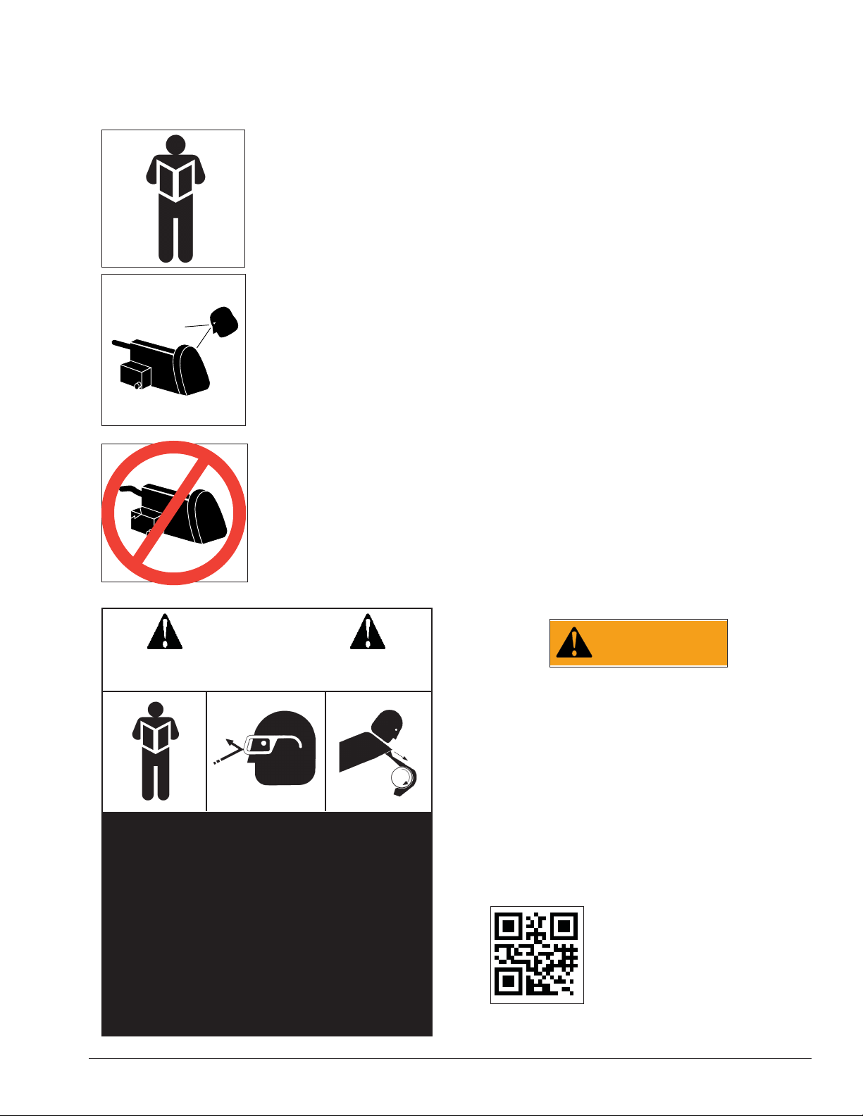
Read entire manual
before installing,
operating, or servicing
this equipment.
Warning
This equipment incorporates parts such as snap
switches and power receptacles which tend to produce
arcs or sparks. Therefore, when located in a service
facility, the unit should be in a room or enclosure provided for the purpose, or should be at least 18” or more
above floor to minimize the risk of igniting fuel vapors.
Cautions and Dangers
1. Eye and face protection requirements:
“Protective eye and face equipment is required to be
used where there is a reasonable probability of injury
that can be prevented by use of such equipment.”
OSHA 1910.133 (a).
Proper maintenance and
inspection is necessary
for safe operation.
Do not operate a
damaged lathe.
CAUTION
Prevent accidents and injury,read and
follow instructions.
Protective goggles, safety glasses, or a face shield
must be provided by the purchaser/user and worn by
the operator of the equipment. Make sure all eye and
face safety precautions are followed by the operator(s).
Keep bystanders out of the area.
2. Do not remove any safety equipment, belt guards,
or shortcut controls or operations.
3. Make sure drums and rotors are properly and
squarely mounted before starting lathe, and that all
parts are secure.
4. Do not wear loose clothing, jewelry, or gloves
when operating or working around a lathe.
5. Do not overload the lathe. Read and understand
the lathe specifications. Overloading is poor machine
tool practice, shortens the life of the lathe, and could
cause a failure resulting in personal injury.
WARNING
Failure to follow danger, warning, and caution
instructions may lead to serious personal
injury or death to operator or bystander or
damage to property. Do not operate this
machine until you read and understand all
the dangers, warnings and cautions in this
manual. For additional copies of either, or
further information, contact:
1. Read and follow instructions.
2. Always wear eye protection, avoid loose
clothing and jewelry.
3. Keep all guards, shields, and covers in place
and in working order.
4. Keep bystanders out of work area.
5. Unplug unit from power source before ser-
vicing or adjusting.
6. Maintain unit properly, keep work surfaces
and work area clean.
Hennessy Industries, Inc.
1601 JP Hennessy Drive
LaVergne, TN 37086-3565
(615) 641-7533 or (800) 688-6359
www.ammcoats.com
Important: Always read and follow operating instructions. • 3
Page 6
Before You Begin
Receiving
The shipment should be thoroughly inspected as soon
as it is received. The signed bill of lading is acknowledgement by the carrier of receipt in good condition of
shipment covered by our invoice.
If any of the goods called for on this bill of lading are
shorted or damaged, do not accept them until the carrier makes a notation on the freight bill of the shorted or
damaged goods. Do this for your own protection.
NOTIFY THE CARRIER AT ONCE if any hidden loss
or damage is discovered after receipt and request the
carrier to make an inspection. If the carrier will not do
so, prepare a signed statement to the effect that you
have notified the carrier (on a specific date) and that the
carrier has failed to comply with your request.
IT IS DIFFICULT TO COLLECT FOR LOSS OR DAMAGE AFTER YOU HAVE GIVEN THE CARRIER A CLEAR
RECEIPT.
File your claim with the carrier promptly. Support
your claim with copies of the bill of lading, freight bill,
invoice, and photographs, if available.
Unpacking the Enclosure
The collector is packed standing on end in the shipping carton. The required brackets and hardware are
included inside the carton. Unpack the unit in an area
large enough to allow the unit to be laid out, opened,
and spread out.
1. Remove the strapping from the shipping container
and remove the top cover.
2. Remove the TOOL BOARD and all other items
packed around the Enclosure. Be careful not to scratch
the viewing WINDOW.
Note: The CHIP BUCKET contains the CHIP TUBE, all
the necessary fasteners, and some of the bracketry.
3. Carefully lay the Enclosure on a pad on the floor.
4. Slide the lower carton off of the unit.
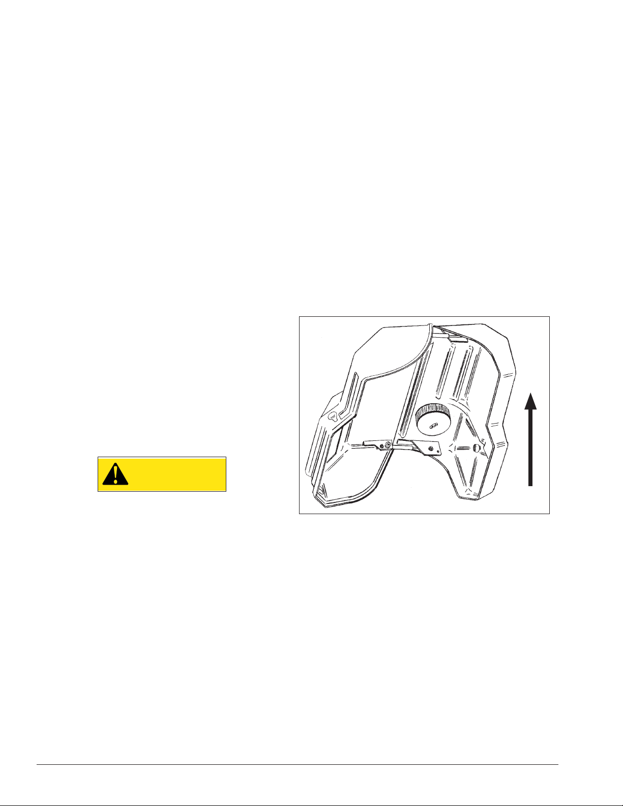
5. Stand the Enclosure on end in the middle of the
work area (fig. 1).
Note: Place a pad or blanket under the Enclosure to
avoid damaging the outside surfaces of the unit.
Although AMMCO’s responsibility ceases upon delivery of the shipment to the carrier, we will gladly assist
in tracing lost shipments. Our willingness to assist in
every possible manner does not make AMMCO responsible for collection of claims or replacement of lost or
damaged materials. Shipping damage claims will not be
handled under warranty.
Set-up
CAUTION
This installation procedure requires two
persons to complete. The Enclosure is large
and heavy and cannot be unpacked, moved,
or positioned safely by one person. The
removal and reinstallation of a lathe requires
two persons.
Use care to avoid dropping or damaging the Enclosure.
Have one person hold the collector while the other
removes packing materials or shipping cartons. During
installation, one person will need to hold the Enclosure
in place on the bench until it is securely fastened to the
bench.
UP
Figure 1 – Stand Unit On End And Open
6. Open the Enclosure and remove any parts or
materials packed inside.
Important: Use care not to scratch the WINDOW.
Preparing the Bench for Installation
7. If a lathe is attached to the bench, remove it now.
8. Move the bench to a position where all sides are
easily accessible, and there is sufficient room to install
the collector.
9. If the bench has a tool board or sign attached,
remove them now. Be sure to remove all mounting for
the board and/or sign as well.
10. Clear the bench of all tools and materials.
4 • Important: Always read and follow operating instructions.
Page 7

Assembling and Installing the Enclosure
11. Lift the Enclosure and set it in place on top of
the bench.
12. Locate the lathe mounting holes in the bottom
of the Enclosure that will be used to mount your lathe.
13. Adjust the position of the Enclosure on the bench
so that the holes in the bottom of the Enclosure align
with the mounting holes in the top of the bench.
14. Use your lathe mounting bolts and nuts to attach
the Enclosure to the bench. Snug the bolts at this time,
but do not tighten.
15. Locate the Enclosure TOOL BOARD and the two
VERTICAL MOUNTING BRACKETS.
16. Locate and remove the 1/4-20 HEX FLANGE NUT
at each end of the HINGE on the lower section of the
Enclosure back wall.
17. Locate and attach the HORIZONTAL MOUNTING
BRACKET to the VERTICAL MOUNTING BRACKETS
using the 1/4-20 x 3/4 PHILLIPS SCREWS and 1/4-20
HEX FLANGE NUTS (fig. 2). Do not tighten.
Horizontal
Mounting
Bracket
Horizontal
Mounting
Bracket
Enclosure
1/4-20 Hex
Flange Nut
Figure 3 – Secure Enclosure To Horizontal Bracket
19. Secure the TOOL BOARD and the brackets to the
Enclosure (fig. 4) using four 1/4-20 x 2-1/2 Hex HD. CAP
SCREWS, FLAT WASHERS and NUTS. Insert the bolts
through the TOOL BOARD, then through the mounting
holes in the Enclosure back wall, and finally through
the vertical brackets. Snug the nuts down, but do not
tighten.
Tool Board
Vertical
Mounting
Bracket
Enclosure
Vertical
Mounting
Bracket
Figure 2 – Mounting Horizontal Bracket
Note: Install control box before tightening TOOL
BOARD to Enclosure. Refer to applicable control box
installation steps, page 8.
18. Secure the Enclosure to the HORIZONTAL
MOUNTING BRACKET by replacing the nuts removed in
step 16, this time including the HORIZONTAL MOUNTING BRACKET in the process (fig. 3). Do not tighten.
Enclosure
1/4-20 x 2-1/2
Hex Hd. Cap
Screw
Figure 4 – Mount Tool Board
20. Remove the lathe mounting bolts from the
mounting holes in the bench and Enclosure.
21. Place your lathe inside the Enclosure.
22. Align the mounting holes in the lathe with the
mounting holes in the Enclosure and the bench.
23. Insert the lathe mounting bolts (supplied with the
2800) through the lathe, the Enclosure, and the bench.
24. Position the Enclosure as far forward and the
lathe as far rearward on the bench as the mounting
bolts will allow.
Washer
Nut
25. Snug nuts onto the lathe mounting bolts. Do not
tighten.
Important: Always read and follow operating instructions. • 5
Page 8

26. Install INNER and OUTER SPACER BRACKETS
in their appropriate location between the bench and
the vertical brackets with the short bracket side of the
spacer next to the bench and the long bracket extending upwards (fig. 5). Use 8 ? BOLTS and ? NUTS. Hand
tighten the fasteners at this time.
30. When the front of the Enclosure is level within
1/4” and the top cover mates properly to the lower
portion, tighten all fasteners securely.
31. Check the fit of the top cover to the lower portion
again after tightening, and readjust as required.
32. Attach the 2” CHIP TUBE to the fitting under the
Enclosure chip tray with the HOSE CLAMP (fig. 7).
Chip Tray
Hose Clamp
Chip Tube
Chip
Bucket
Figure 5 – Completed Bracket Assembly
27. The top cover must mate properly with the lower
portion of the Enclosure when closed. If they do not,
shimming or adjusting the brackets of the rear support
structure is required.
28. Raise the top cover and measure the distance
from the floor to the front lip of the lower portion of the
Enclosure. Measure in multiple locations.
The measurement should not vary more than 1/4”
across the front of the Enclosure (fig. 6). If it does vary
by more than 1/4”, shim the structure until the measurements are satisfactory.
Figure 7 – Chip Tube And Chip Bucket
33. Slip the other end of the tube into the hole in
the top of the CHIP BUCKET and move the bucket into
place under the chip tray.
34. Route the lathe power cord through the hole
in the back of the Enclosure and plug it into a suitable
power source.
35. Plug the Enclosure power cord into suitable
power source.
36. Fasten the HANDLE and PULL STRAP to the
hood using two 5/16-18 x 1 1/4 SCREWS, two 5/16 ID
WASHERS and two 5/16 LOCK NUTS.
After placing the screws through the HANDLE and
the plastic, slide the PULL STRAP over the right-hand
screw. Then slide washers over both screws and secure
with the nuts.
5/16 Lock Nut
5/16 ID
Washer
Hood
Pull Strap
Handle
Figure 6 – Measure In Multiple Locations
29. Install alignment SHIMS at the fasteners between
5/16-18 x 1 1/4
Screw
the SPACER BRACKETS and the VERTICAL MOUNTING
BRACKETS as necessary to achieve satisfactory mea-
Figure 8 - Handle And Pull Strap Assembly
surements across the front.
The Enclosure may also be shifted within the tolerances allowed by the lathe mounting bolts to fine tune
the adjustment.
6 • Important: Always read and follow operating instructions.
Page 9

Assembling Shield – 2801 and 2802
1. Position the SHIELD TOP and SHIELD SIDE (RIGHT
HAND AND LEFT HAND) assembly, as shown in fig. 9.
3 Holes In Top Shield
Electrical Wiring — 2801 Only
1. Remove the cover on the round box by taking out
the four screws.
Lower Strut
Bracket
4 Holes
In Shield
Bracket
Figure 9 - Shield Assembly
2. Place 1/4-20 SCREWS through the SHIELD TOP
and SHIELD SIDE assembly and the plastic base from
the front side. Attach WASHERS and NUTS from the
rear of the unit and tighten.
3. Place a 10-24 x 1/2 PHILLIPS PAN HD. SCREW
through the top side of the SHIELD HINGE and through
the corresponding hole in the plastic CHIP SHIELD.
4. Position the SHIELD SUPPORT so that its beveled
corners are facing the beveled corners on the mating
SHIELD STOP.
10-24 x 1/2 Phillips Pan
Hd. Screw
Shield Hinge
Hood Switch
Cable
Box
Mounting
Tab
Figure 11 - Electrical Box
2. Insert the emergency stop switch cable through
the empty box connector until the outside jacket just
enters the round box, or is completely inside the connector. Tighten the two connector screws.
3. Loosen the two screws that are clamping the foot
switch cable enough to push the hood switch cable into
the box. Tighten the two connector screws.
4. Remove the yellow wire nut from the BLACK wire
of the foot switch and add the BLACK wire from the
hood switch. Screw connector on tightly.
Emergency Stop
Switch Cable
Box Mounting
Tab
Chip Shield
Shield Stop
Shield
Support
10-24 Lock
Nut, ESNA
Figure 10- Plastic Shield Assembly
5. Attach NUT to SCREW. Assemble the remaining
five SCREWS and NUTS before tightening any of them.
6. Attach electrical box assembly to the back of the
Enclosure using two 1/4” BOLTS, WASHERS and NUTS.
5. Join the WHITE wires from all three switches
together with a yellow wire nut.
6. Connect the BLACK wire from the STOP SWITCH
to the jumper wire from the outlet using a yellow wire
nut.
7. Re-attach the round cover plate and gasket to the
box with the four screws. Refer to Wiring Schematic —
2801 on page 16.
Important: Always read and follow operating instructions. • 7
Page 10

Additional Installation — 2802 Only
1. Remove the four screws holding the control box
cover on and lay the cover and screws to the side. Position the box on the back of the Enclosure as shown in
(fig. 12), with the holes in the control box in line with the
holes in the Enclosure. Use the 1/4 SCREWS, NUTS,
and WASHERS provided to attach the control box.
Figure 12 - Position Control Box Onto Enclosure
4. Wire the emergency stop switch, to the control
box as shown in the wiring schematic and figure 14.
Tighten cable connector screws.
Black
White
Figure 14 - Control Box Wiring
5. Attach the HOOD SWITCH and HOOD SWITCH
MAGNET assemblies to the Enclosure using the #10
HARDWARE as shown in figure 15.
2. Remove the cover from the START/STOP PUSHBUTTON SWITCH. Position the switch as shown in
figure 13 and attach the switch with #10 SCREWS,
WASHERS, and NUTS. Reinstall the cover.
Figure 13 - Fasten Switch On Enclosure
3. Insert the emergency stop switch cable through
the right hand of the control box until the outside jacket
is inside the box.
Figure 15 - Attach Hood Switch To Enclosure
6. Use the provided cable ties and attachment pads to
fasten the wires to the wires to the Enclosure.
7. Replace the control box cover and tighten the four
screws.
8 • Important: Always read and follow operating instructions.
Page 11

Operation
Operation — 2800 Only
1. Plug the fan cord into a 115V wall receptacle when
lathe is in use.
Operation — 2801 Only
Important: Do not plug fan or lathe into a wall power
source. Fan and lathe power cords must be plugged
into the Enclosure electrical receptacle or the safety
features will not function.
1. Plug the fan cord into the Enclosure receptacle.
2. Plug the lathe cord into the Enclosure receptacle.
3. Plug the ELE power cord into an approved power
source.
4. Push the lathe power switch to the ON position.
5. Lower shield.
6. Lower hood and pull the emergency switch out.
Lathe will come ON.
7. Push stop switch in and the lathe will shut off.
Note: Lathe will only run under one of these condi-
tions:
(1.) Hood is fully lowered.
(2.) Foot pedal is depressed–use only for setting up
tool bit depth of cut prior to lowering hood.
Operation — 2802 Only
CAUTION
Depressing the footswitch will start the
brake lathe WITHOUT the shields and guards
in place so that the set-up of the brake lathe
tooling can be accomplished. Keep fingers
out of the rotating workpiece hazard areas.
Important: Do not plug fan or lathe into a wall power
source. Fan and lathe power cords must be plugged
into the Enclosure electrical receptacle or the safety
features will not function.
1. Plug the fan cord into the Enclosure receptacle.
2. Plug the lathe cord into the Enclosure receptacle.
3. Plug the ELE power cord into an approved power
source.
4. Push the lathe power switch to the ON position.
Note: The lathe can be stopped at any time by lifting
the hood, pressing the red emergency STOP button, by
pressing the STOP button on the outside (right-handlocated switch), or by moving the lathe toggle switch to
the OFF position. If lathe is stopped at any time, it can
only be restarted by lowering the hood and pressing
the ON button switch at the right end of the Enclosure.
5. Install brake drum or rotor, and necessary silencer(s).
6. With CHIP SHIELD in place, safety glasses on, and
hands out of the way of the work-piece, the foot pedal
can be pressed to turn the lathe on. Set the tool(s) as
required for proper cut and remove your foot from the
pedal to stop the lathe.
7. Lower the Enclosure hood.
8. Insure that no bystanders are in front of the Enclo-
sure.
9. Proceed to the right side of the Enclosure and
press the START button to turn the lathe on and start
the cut process.
10. When the cut is complete, the lathe can be
stopped by lifting the Enclosure hood.
NOTICE: This AMMCO Model 2802 Brake Lathe
Enclosure complies with the CSA Z432-04 Safeguarding
of Machinery Standards (Reaffirmed 2009 edition). The
enclosed installation and operation instructions must
be followed. Refer to the instruction manual that was
provided with the brake lathe that is to be installed in
this Enclosure. Read the Hazards in this manual and in
the brake lathe manual before installing and operating
the brake lathe. There are Hazardous areas that must
be protected for your safety. DO NOT operate the
brake lathe or the Enclosure if any of the safety devices
are not in working condition. Correct any issues with
replacement parts only from AMMCO to insure that the
parts comply with the requirements of CSA Z432-04
Safeguarding of Machinery Standard.
Important: Always read and follow operating instructions. • 9
Page 12

Maintenance
1. Check the air filter regularly for contamination. The
replacement interval for the filter is directly proportional
to use. Replace the filter when the air flow is diminished.
The filter is the same air filter typically used in GM
passenger cars with the 454 cubic inch gasoline engine.
Seal the used filter in a plastic bag before disposal.
2. Check the CHIP TUBE periodically to make sure it
is securely attached to the chip tray. Inspect the tube
for holes or cracks. Replace the tube if it is damaged
or leaks.
The CHIP TUBE is a typical 2” pre-heater hose.
3. If the gas struts are damaged, or begin to weaken,
replace them with struts of the same force and length
as the originals. Failure to use the correct strut may
create a hazard to the operator. Replacement struts are
available from AMMCO.
4. Check the CHIP BUCKET and empty it before it
reaches capacity. If the CHIP BUCKET becomes full,
chips and other material will back up into the chip tray
and the interior of the Enclosure. Dispose of the material in the bucket properly.
Electrical Source
115V, 60 Hz, 1 PH, Fused @ 20 A
10 • Important: Always read and follow operating instructions.
Page 13

Parts Identifi cation
2800, 2801, and 2802
7
6
4
5
3
2
1
8
9
10
19
12
22
23
24
17
20
21
Installation Hardware
4 5 3 29
14
27
13
17
17
17
16
12
15
16
26
28
25
18
11
12
ITEM PART NO. QTY. DESCRIPTION
1 940030 2 Vertical Mounting Bracket
2 940028-01 2 Outer Spacer Bracket
940028-02 2 Inner Spacer Bracket
3 940027 1 Horizontal Mounting Bracket
4 924100 14 1/4-20 x 3/4 Phillips Screw
5 924557 20 1/4-20 Hex Flange Nut
6 929906 1 Window
7 902322 16 10-32 x 1/2 Screw
940137 16 #10 Stainless, Blk Oxide Washer
8 940082 1 Hose Clamp
9 940000 1 Chip Tube
10 929999 1 Chip Bucket w/Lid
11 940052 2 Gas Strut
12 940053 2 Ball Stud
13 929969 1 Tool Board
14 9301818 6 1/4-20 x 2-1/2 Hex Hd. Cap Screw
15 940025-01 1 Gas Strut Bracket
940025-02 1 Gas Strut Bracket
30 31 32
ITEM PART NO. QTY. DESCRIPTION
16 940084 14 5/16 x 18 x 1-1/4 Screw
17 8182178 18 5/16 x 18 Hex Flange Nut
18 940024-01 1 Gas Strut Bracket
940024-02 1 Gas Strut Bracket
19 940002 1 Fan Assembly, 115V
20 929905 1 Filter
21 929864 1 Filter Cover
22 906358 1 1/4-20 Wing Nut
23 940089 1 Power Cord Assembly
24 940350 1 Handle
25 940351 1 Pull Strap
26 900278 2 5/16 I.D. Washer
27 940381 2 5/16-18 x 1-1/4 Screw
28 8181183 2 5/16 Lock Nut
29 940274 4 1/2-13 x 2-1/2 UNC Screw
30 920992 8 Shim
31 904379 9 Flat Washer
32 906354 9 1/4-20 x 1 Hex Hd. Cap Screw
Important: Always read and follow operating instructions. • 11
Page 14

Shield Assembly — 2801 and 2802
43
33
34
36
35
36
40
37
39
41
38
Wiring View — 2801 Only
ITEM PART NO. QTY. DESCRIPTION
44 940121 1 Power Cover
45 90044 1 Foot Switch Assembly
46 940051 1 Relay, SPST, 1 H.P.
47 940120 1 Duplex Receptacle, 20A
48 940125 1 Hood Switch
49 940220 1 Stop Switch
50 940221 1 Stop Switch Plate
42
ITEM PART NO. QTY. DESCRIPTION
33 ------- 1 Right Hand Shield Side
34 ------- 1 Left Hand Shield Side
35 ------- 1 Shield Top
36 ------- 1 Pop Rivet, 3/16 x 0.250
37 ------- 1 10-24 x 1/2, Phillips Pan Hd Screw
38 ------- 1 10-24 Lock, ESNA Nut
39 ------- 1 Shield Hinge
40 ------- 1 Shield Stop
41 ------- 1 Shield Support
42 940417 1 Chip Shield (with decal)
43 940166 1 Warning Decal
46
48
47
49
50
44
45
12 • Important: Always read and follow operating instructions.
Page 15

Foot Switch Assembly — 2801 and 2802
53
54
Magnet Mounting — 2801 Only
ITEM PART NO. QTY. DESCRIPTION
51 940057 1 Switch Magnet Shim
52 940050 1 Switch Magnet
53 940124 1 Foot Switch Cord Assembly
54 95000204 1 Warning Decal
52
51
ITEM PART NO. QTY. DESCRIPTION
55 9109947 1 Hood Switch Magnet
56 9111447 1 5/16-18 x 1 Nylon HHCS Screw
57 ------- 1 5/16-18 Hex Washer Hd Whiz Lock
Nut
57
56
55
Important: Always read and follow operating instructions. • 13
Page 16

Hood Switch Mounting — 2801 Only
58
58
61
60
Hood Switch Mounting — 2802 Only
68
64
65
66
67
63
ITEM PART NO. QTY. DESCRIPTION
58 940125 1 Hood Switch
59 ------- 2 4-40 x 5/8 Socket Hd Cap Screw
60 ------- 2 4-40 Hex Kep Nut
61 ------- 4 Plain Washer, #4, Type B
62 ------- 1 Wire Tie
59
61
ITEM PART NO. QTY. DESCRIPTION
63 ------- 4 #10-24 Hex Nut
64 ------- 4 10-24 x 3/4 SBHCS Screw
65 ------- 4 #4-40 x 3/8 SHCS Screw
66 ------- 4 0.112-40 Kep Hex Nut, Zinc
67 ------- 4 #10 Plain Washer, Zinc
68 95000194 1 Base Bracket
69 95000195 1 Hinge Bracket
70 95000206 1 Magnetic Safety Switch
70
69
14 • Important: Always read and follow operating instructions.
Page 17

Stop Switch Mounting — 2801 and 2802
71
72
ITEM PART NO. QTY. DESCRIPTION
71 940220 1 Start/Stop Push-button Switch —
2801
95000205 1 Start/Stop Push-button Switch —
2802
72 940221 1 Stop Switch Decal — 2801
95000207 1 Stop Switch Decal — 2802
Important: Always read and follow operating instructions. • 15
Page 18

Wiring Schematic
Wiring Schematic — 2801
16 • Important: Always read and follow operating instructions.
Page 19

Wiring Schematic — 2802
G
940120
RECEPTACLE
G
WHITE 12 AW
REEN 14 AW
NL
G
G
RED 22 AW
G
.
O
N.
LEAR 22 AW
TART
C
S
WHITE
G
G
G
K 14 AW
C
E 22 AW
U
BLA
BL
G
K 14 AW
C
BLA
G
AW
6
K 1
C
BLA
G
AW
6
K 1
C
BLA
G
K 22 AW
C
BLA
5
I4 I
3
I1 I2 I
0
MI
CO
C
+-
24VD
95000209
3
Q
2
Q
RELAY
1
Q
0
Q
G
REEN 22 AW
G
P
.
O
C
T
N.
S
95000210
BLACK 22 AW
G
3
12
WHITE 14 AW
G
WHITE 12 AW
TO AC SINGLE POWER OUTLET
115V, 60Hz, 1PH, Fused @ 20A
REEN 12 AW
G
LN
H
C
WIT
S
P
O
T
95000205
S
O
EM
WHITE 14 AW
P
O
T
S
E
G
G
K 12 AW
C
BLA
G
K
WN
E
C
O
U
WHITE
BR
BL
BLA
H
C
WIT
S
D
95000206
OO
H
G
AC/24VDC
P
95000203
V-
EARTH
G
REEN 22 AW
G
V+
G
RED 22 AW
K 22 AW
C
BLA
N
O
TI
C
N
JU
: WIRE
ay
l
e
R
940051
1
4
G
AW
6
RED 1
G
G
AW
2
3
6
K 1
C
BLA
WHITE 14 AW
G
K 14 AW
C
BLA
T SWITCH
F
OO
G
AW
6
K 1
C
BLA
WER
O
N
L
Important: Always read and follow operating instructions. • 17
Page 20

940086 07 09/2012 © Copyright 1996 Hennessy Industries and COATS® All Rights Reserved. Printed in USA
 Loading...