

AMMCO 2760, 2760-50 User Manual
Inch & Metric Rotor Micrometers
Operating Instructions with Parts
Identification
No. 902760
No. 902760-50
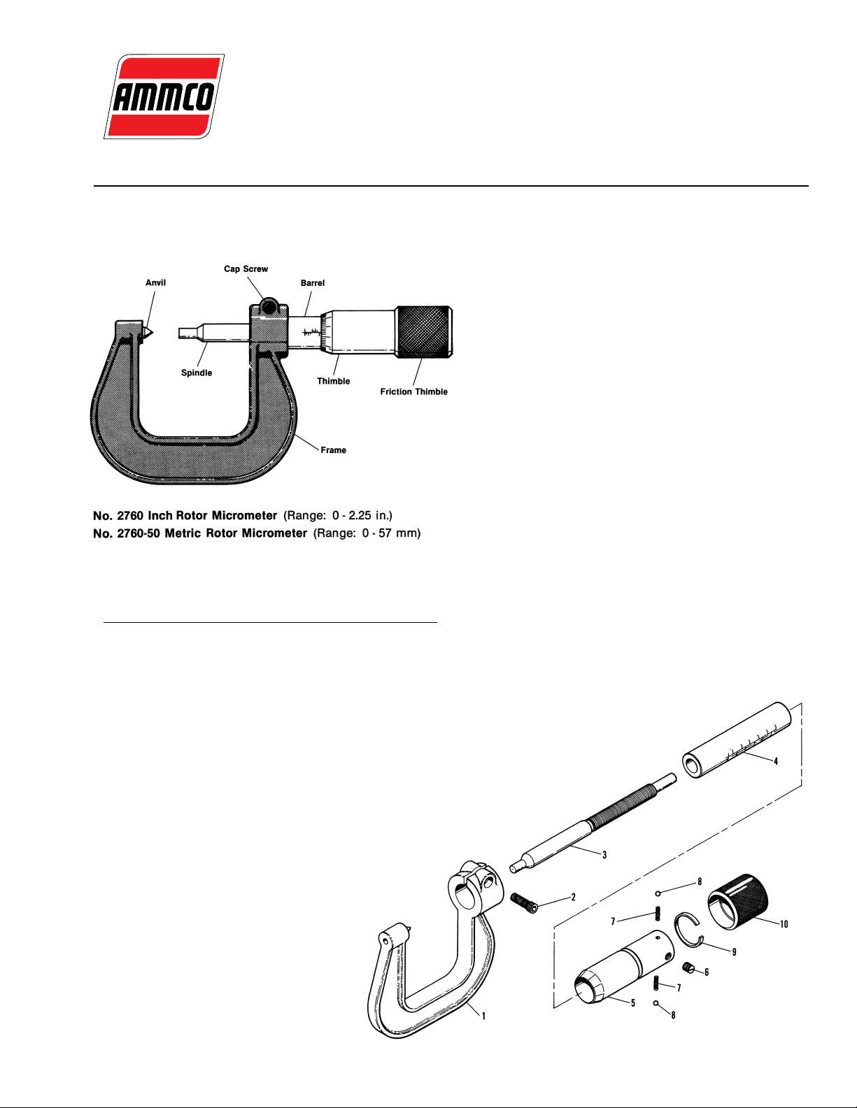
Item Part No. Qty. Description
1 924999 1 Frame/Anvil Assembly
2 900205 1 Cap Screw
3 922402 1 Inch Spindle
922407 1 Millimeter Spindle
4 922396 1 Inch Barrel
922405 1 Millimeter Barrel
5 922397 1 Inch Thimble
922406 1 Millimeter Thimble
6 906148 1 Set Screw
7 922404 2 Spring
8 920379 2 Detent Ball
9 922403 1 Friction Strip
10 922398 1 Friction Thimble
Rotor Condition
Measure the rotor’s thickness at three (3) or more
points around its circumference about one (1) inch (2.54
cm) in from the outer edge. Note: If the rotor has
grooves worn in its friction surfaces measure its thickness with the point of the anvil in the deepest groove. If
the rotor thickness varies between readings the rotor
should be machined. The rotor should be replaced if the
rotor’s thickness at any point is less than the minimum
established by the vehicle manufacturer, or if it will be
less after reconditioning.
Calibration
1. Loosen the cap screw holding the micrometer
assembly in the frame.
2. Zero the thimble to the zero mark of the barrel by
turning the friction thimble.
3. Push the thimble/barrel “assembly” against the
anvil.
4. Tighten the clamp screw while maintaining the set-
ting.
5. Check the zero setting by backing the spindle away
from the anvil and closing the micrometer by its friction
thimble.
6. If the micrometer does not read zero, loosen the
cap screw and reset the thimble to the same number of
divisions on the other side of the zero mark on the thimble. Repeat steps 3, 4, and 5.
922410 06 07/02 © COPYRIGHT 2002 HENNESSY INDUSTRIES AND AMMCO ALL RIGHTS RESERVED PRINTED IN U.S.A.
AMMCO, Inc. • Hennessy Industries • 1601 J.P. Hennessy Drive, LaVergne, TN 37086-3565
(800) 688-6359 • (615) 641-7533 • (615) 641-5104 FAX • www.ammcoats.com
 Loading...