

Page 1
Operating Instructions
with Parts Identification
READ these instructions before placing unit in
service. KEEP these and other materials delivered
with the unit in a binder near the machine for
ease of reference by supervisors and operators.
Model 2635 - Car/Light Truck
Model 2645 - Heavy-Duty Truck
Scribe Toe Gauges
®
1601 J. P. Hennessy Drive, LaVergne, TN USA 37086-3565 615/641-7533 800/688-6359 Manual Part No.: 924230 06
HENNESSY INDUSTRIES INC. Manufacturer of AMMCO
®
, COATS®and BADA®Automotive Service Equipment and Tools. Revision: 01/05
Page 2
2 • AMMCO
Assembled Toe Gauge
In measuring toe we are determining if the two
wheels are closer together at the front or at the back
of the tires. The AMMCO toe gauge measures this
accurately by eliminating error due to tire or wheel
runout.
Drive the vehicle onto an alignment rack or level surface. Check for worn front end parts and loose wheel
bearings. Check for proper tire pressure and equal tire
tread depths.
1. Raise the vehicle and, while rotating each tire,
make a wide mark near the center of the tread with
chalk.
2. Place the toe gauge in front of the wheels and
adjust it so the pointers are near the center of the
chalk mark on each wheel.
3. Scribe a line in the chalk mark on each tire by holding the respective pointer securely against the tire in
one position while rotating the tire, Fig. 1. Note: The
beginning and the end of the line must intersect, if
not, re-chalk and re-scribe.
Figure 1 - Scribing Line In Chalk Mark
4. Lower the vehicle on a set of turntables and
bounce it in the middle of the bumper to allow the
suspension to assume its natural attitude.
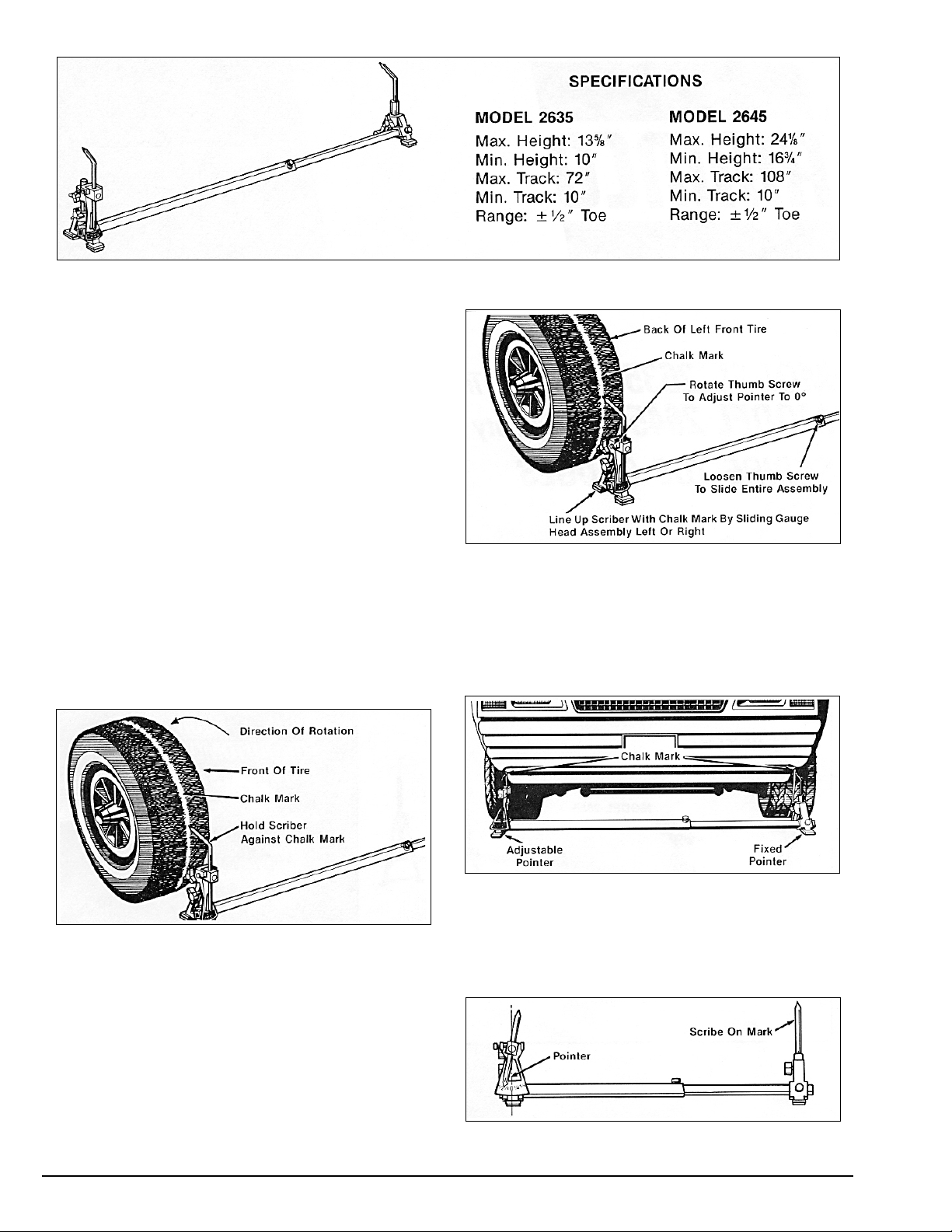
5. Place the toe gauge behind the tires. Adjust the
pointers to spindle height. Align the fixed pointer with
the line scribed on the tire. Set the adjustable pointer
at “0”, loosen the thumb screw in the center of the
gauge, and slide the entire assembly so the adjustable
pointer is aligned to the line scribed on the other tire.
Recheck that all thumb screws are tight and that both
pointers are aligned with the scribe marks, Fig. 2.
Figure 2 - Gauge Placed Behind Front Wheels To Measure
Distance Between Chalk Marks
6. Move the gauge, without bumping the pointers, to
the front of the wheels. Set the stationary pointer on
the left tire’s scribe mark. Align the adjustable pointer
with the right tire scribe mark by turning the pointer
adjusting thumb screw, Fig. 3.
Figure 3 - Aligning Pointer With Chalk Marks At The Front Of
The Front Wheels
7. READ THE SCALE. If the pointer has moved to the
right, toe-out readings are indicated. If the pointer has
moved to the left of zero, toe-in readings are indicated, Fig. 4. RECORD THE READING.
Figure 4 - Pointer To Left Of Zero; Toe-In
Page 3

AMMCO • 3
Parts Identification
Item Part No. Qty. Description
1 924222 1 Gauge Head Assembly,
Car
924217 1 Gauge Head Assembly,
Truck
2 903180 2 Screw, Set Cup Point
3 924221 1 Leg, Car
924216 1 Leg, Truck
4 910745 3 Plug
5 906854 3 Screw, Lock
6 924210 1 Scale
7 907838 1 Screw, Thumb
8 924220 1 Post, Pointer Car
924214 1 Post, Pointer Truck
9 924215 1 Quadrant
10 925640 1 Nut, Lock
11 900212 1 Screw, Set
12 924212 1 Pivot, Pointer
13 924213 1 Pointer
14 920688 1 Spring, Plunger
15 907824 1 Plunger, Pointer
16 924211 1 Screw, Shoulder
17 923584 1 Cover, Lock Knob
Item Part No. Qty. Description
18 907881 *2 Bar, Head
19 907888 1 Bar, Scribe
20 907890 *2 Screw, Thumb
21 924227 1 Scribe Assembly, Car
924226 1 Scribe Assembly, Truck
22 925142 4 Pad, Foam
23 924223 1 Leg, Car
924216 1 Leg, Truck
24 907838 1 Screw, Thumb
25 924228 1 Shaft, Scriber Car
924225 1 Shaft, Scriber Truck
26 924224 1 Scriber
*Quantity 1 For Cars
Page 4

924230 06 01/05 © Copyright 1987 Hennessy Industries and AMMCO All Rights Reserved Printed in USA
 Loading...