

Page 1

Assembly Instructions
with Parts Identification
READ these instructions before placing unit in
service. KEEP these and other materials delivered
with the unit in a binder near the machine for
ease of reference by supervisors and operators.
2500 • 2510 • 2515
Single Brake Lathe
Benches; Sign Kit
®
1601 J. P. Hennessy Drive, LaVergne, TN USA 37086 615/641-7533 800/688-6359 Manual Part No.: 940058 02
HENNESSY INDUSTRIES INC. Manufacturer of AMMCO
®
, COATS®and BADA®Automotive Service Equipment and Tools. Revision: 06/02
Page 2
2 • 2500/2510/2515 Lathe Benches
Brake Lathes
When You Receive
Your Bench
Unpack the bench parts and check them against the
parts list on the last page of this manual. Make sure
you have all the parts listed – and the quantities listed.
Report any shortages immediately.
Preparing the Bench for Use
1. Carefully lay the bench on its side.
2. Screw a leveling foot into the threaded hole
located at each corner of the bench (4 locations).
3. Once the bench is placed in its final location, level
the bench by raising or lowering the 4 leveling feet as
necessary.
Attaching the Tool Board and Sign
1. Use 2 truss head screws and 2 flange nuts to
attach each spacer to the rear flange of each end
panel. Use the holes at the top of each flange. Wrench
tighten the nuts.
Figure 1 – Attach Spacers to End Panels
2. Use 2 truss head screws and 2 flange nuts to
attach an upright to the spacer. Wrench tighten the
nuts. Repeat for the other spacer and upright.
Figure 2 – Attach Uprights to Spacers
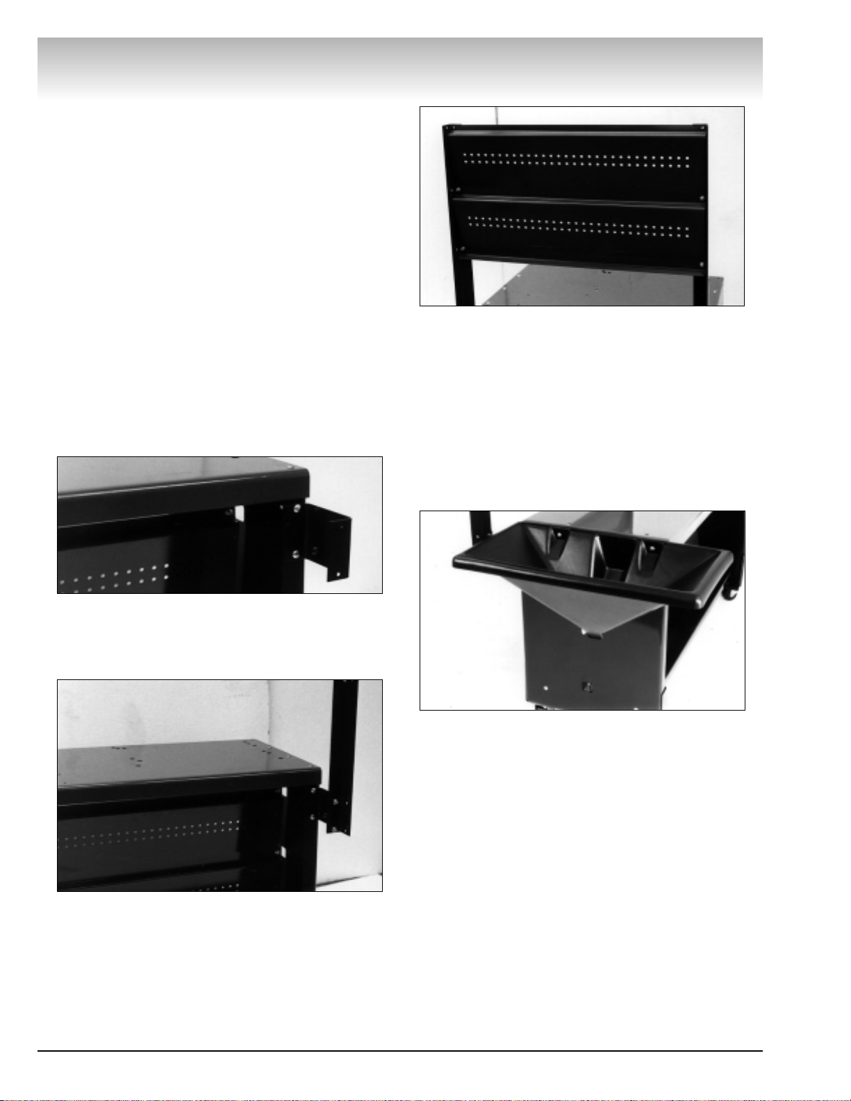
3. Position the upper tool board behind the front
flanges of the uprights with the tool board flange on
the bottom and facing the rear. Secure the tool board
to the lower and middle holes in the uprights with
truss head screws and nuts. Hand tighten the nuts
only.
Figure 3 – Attach Upper Tool Board
4. Position the sign in front of the uprights and the
tool board. Align the holes in the sign with the holes
in the board and the uprights and secure with truss
head screws and nuts. Tighten all tool board nuts at
this time.
5. Attach lathe to bench.
6. Attach the funnel to the 2 holes in the top of the
left end panel. Use 2 truss head screws and flange
nuts.
Figure 4 – Attach Funnel
Page 3

2500/2510/2515 Lathe Benches • 3
Parts Identification
Quantity
Item Part 2500 2510 2515 Description
1 940062 4 4 -- Adjustable Foot
2 923749 1 1 -- Chip Bucket
3 923748 1 1 -- Chip Funnel
4 924100 16 2 14 1/4-20 x 3/4 Truss Head Screw
5 940055 1 -- 1 Tool Board, Short
6 924557 16 2 14 1/4-20 Hex Flange Serrated Face Nut
7 925255 1 -- 1 Sign
8 940056 2 -- 2 Upright
9 925237 2 -- 2 Bracket
10 --------
not available separately Base Weldment
* 909966 35 20 15 Storage Hook
* Item not shown
Brake Lathes
Page 4

940058 02 06/02 © Copyright 1993, 2002 Hennessy Industries and AMMCO All Rights Reserved Printed in USA
 Loading...