

Page 1
ARX 23-2
ARX 26-2
TANDEM ROLLER
KUBOTA D1803-M-DI-E3B
EU Stage IIIA, U.S. EPA Tier 4i
OPERATING MANUAL
EDITION 07/2021 EN
ARX 23-2 KU St IIIA / T4i Product Identification Number 3007951 ARX 26-2 KU St IIIA / T4i Product Identification Number 3005357 -
Page 2

Page 3

Výrobce /
Ammann Czech Republic a.s.
Adresa /
Address / Adresse:
Náchodská 145, CZ-549 01 Nové Město nad Metují, Czech Republic
IČ /
000 08 753
Ing. Radek Ostrý
Ammann Czech Republic a.s.
Náchodská 145, CZ-549 01 Nové Město nad Metují, Czech Republic
Popis strojního zařízení /
Description of the machinery / Beschreibung der
Maschineneinrichtung:
Označení /
Tandemový válec / Tandem roller / Tandemwalze
Typ /
ARX 23-2
Verze /
Product Identification Number:
Motor /
Engine / Motor:
Kubota D1803-M-DI-E3B, vznětový, jmenovitý výkon (SAE J1995): 24,8 kW, jmenovité otáčky:
Strojní zařízení – směrnice 2006/42/ES /
Machinery Directive 2006/42/EC /
Elektromagnetická kompatibilita – směrnice 2014/30/EU /
Electromagnetic Compatibility
Emise hluku – směrnice 2000/14/ES /
Noise Emission Directive 2000/14/EC /
ČSN EN ISO 12100, ČSN EN 500-1+A1, ČSN EN 500-4, ČSN EN ISO 4413,
Notifikovaná osoba č. 1016 / Notified Body No.: 1016 / Notifizierte Stelle Nr.: 1016
Státní zkušebna strojů a.s., Třanovského 622/11, 163 04 Praha 6–Řepy, ČR. / The
Použitý postup posouzení shody /
Na základě směrnice 2000/14/ES příloha VI /
Pursuant to the Noise Emission Directive
Naměřená hladina akustického výkonu /
Measured sound power level /
Gemessener Schallleistungspegel:
LWA = 103 dB
Garantovaná hladina akustického výkonu /
/ Garantierter Schallleistungspegel:
LWA = 104 dB
Místo a datum vydání / Place and date of issue / Ort und Datum der Ausgabe:
Nové Město nad Metují,
Jméno /
Name / Name:
Jiří Sychra
Funkce /
Grade / Stelle:
Logistics Manager
Podpis /
Signature / Unterschrift:
Originální ES/EU prohlášení o shodě je dodané s dokumenty během expedice stroje. /
ES / EU Prohlášení o shodě
(Původní ES/EU prohlášení o sho dě /
Original EC/EU Declaration of conformity / Ursprüngliche EG-/EU-Konformitätserklärung
)
EC / EU Declaration of conformity / EG-/EU-Konformitätserklärung
(Překlad původního ES/EU prohlášení o shodě /
Translation original EC/EU Declaration of conformity / Übersetzung der ursprünglichen EG-/EU-Konformitätserklärung
)
and address of the person, who keeps the technical documentation according
expedition of machine. / Das Original der EG-/EU-Konformitätserklärung wird mit den Unterlagen während des Versands der Maschine mitgeliefert.
Manufacturer / Hersteller:
Identification Number / Ident.-Nr:
Jméno a adresa osoby pověřené sestavením technické dokumentace
podle 2006/42/ES a jméno a adresa osoby, která uchovává technickou
dokumentaci podle 2000/14/ES /
Name and address of the person
authorised to compile the technical file according to 2006/42/EC and name
to 2000/14/EC / Name und Adresse der mit der Zusammenstellung der
technischen Dokumentation beauftragten Person gemäß 2006/42/EG und
Name und Adresse der mit der Aufbewahrung der technischen
Dokumentation beauftragten Person gemäß 2000/14/EG:
Designation / Bezeichnung:
Type / Typ:
Version / Version:
The original EC/EU Declaration of Conformity is supplied with documents during
Prohlašujeme, že strojní zařízení splňuje všechna příslušná ustanovení
uvedených směrnic /
We declare, that the machinery fulfils all the relevant
provisions mentioned Directives / Wir erklären, dass die
Maschineneinrichtung sämtliche entsprechenden Bestimmungen
aufgeführter Richtlinien erfüllt:
Harmonizované technické normy a technické normy použité kposouzení
shody /
The harmonized technical standards and the technical standards
applied to the conformity assessment / Harmonisierte technische Normen
und für die Beurteilung der Konformität verwendete Normen:
Osoby zúčastněné na posouzení shody /
Bodies engaged in the conformity
assessment / An der Konformitätsbeurteilung beteiligte Personen:
To the conformity assessment applied
procedure / Verwendetes Vorgehen der Konformitätsbeurteilung:
2400 min-1. /
speed: 2400 RPM. / Kubota D1803-M-DI-E3B, Dieselmotor, Nennleistung (SAE J1995): 24,8
kW, Nenndrehzahl: 2400 min
Kubota D1803-M-DI-E3B, Diesel, nominal power (SAE J1995): 24,8 kW, rated
-1
.
Maschineneinrichtung – Richtlinie 2006/42/EG
Directive 2014/30/EU / Elektromagnetische Kompatibilität – Richtlinie 2014/30/EU
Lärmemissionen – Richtlinie 2000/14/EG
Government Testing Laboratory of Machines J.S.C., Třanovského 622/11, 163 04 Praha
6–Řepy, Czech Republic / Staatliche Prüfstelle für Maschinen AG,
Třanovského 622/11, 163 04 Praha 6–Řepy, Tschechische Republik.
2000/14/EC, Annex VI / Aufgrund der Richtlinie 2000/14/EG, Anlage VI
Guaranteed sound power level
Osoba zmocněná k podpisu za výrobce /
Signed by the person entitled to deal in the name of manufacturer / Zeichnungsberechtigter für den Hersteller:
CZ / EN / DE
Page 4

Výrobce /
Manufacturer / Hersteller:
Ammann Czech Republic a.s.
Adresa /
Address / Adresse:
Náchodská 145, CZ-549 01 Nové Město nad Metují, Czech Republic
IČ /
Identification Number / Ident.-Nr:
000 08 753
Ing. Radek Ostrý
Ammann Czech Republic a.s.
Náchodská 145, CZ-549 01 Nové Město nad Metují, Czech Republic
Popis strojního zařízení /
Description of the machinery / Beschreibung der
Maschineneinrichtung:
Označení /
Tandemový válec / Tandem roller / Tandemwalze
Typ /
ARX 26-2
Verze /
Version / Version:
Product Identification Number:
Motor /
Engine / Motor:
Kubota D1803-M-DI-E3B, vznětový, jmenovitý výkon (SAE J1995): 24,8 kW, jmenovité otáčky:
Strojní zařízení – směrnice 2006/42/ES /
Machinery Directive 2006/42/EC /
Elektromagnetická kompatibilita – směrnice 2014/30/EU /
Electromagnetic Compatibility
Emise hluku – směrnice 2000/14/ES /
Noise Emission Directive 2000/14/EC /
ČSN EN ISO 12100, ČSN EN 500-1+A1, ČSN EN 500-4, ČSN EN ISO 4413,
Notifikovaná osoba č. 1016 / Notified Body No.: 1016 / Notifizierte Stelle Nr.: 1016
Státní zkušebna strojů a.s., Třanovského 622/11, 163 04 Praha 6–Řepy, ČR. / The
Použitý postup posouzení shody /
Na základě směrnice 2000/14/ES příloha VI /
Pursuant to the Noise Emission Directive
Naměřená hladina akustického výkonu /
Measured sound power level /
Gemessener Schallleistungspegel:
LWA = 103 dB
Garantovaná hladina akustického výkonu /
Guaranteed sound power level
LWA = 104 dB
Místo a datum vydání / Place and date of issue / Ort und Datum der Ausgabe:
Nové Město nad Metují,
Jméno /
Name / Name:
Jiří Sychra
Funkce /
Grade / Stelle:
Logistics Manager
Podpis /
Signature / Unterschrift:
Originální ES/EU prohlášení o shodě je dodané s dokumenty během expedice stroje. /
ES / EU Prohlášení o shodě
(Původní ES/EU prohlášení o sho dě /
Original EC/EU Declaration of conformity / Ursprüngliche EG-/EU-Konformitätserklärung
)
EC / EU Declaration of conformity / EG-/EU-Konformitätserklärung
(Překlad původního ES/EU prohlášení o shodě /
Translation original EC/EU Declaration of conformity / Übersetzung der ursprünglichen EG-/EU-Konformitätserklärung
)
and address of the person, who keeps the technical documentation according
Osoby zúčastněné na posouzení shody /
Bodies engaged in the conformity
expedition of machine. / Das Original der EG-/EU-Konformitätserklärung wird mit den Unterlagen während des Versands der Maschine mitgeliefert.
Jméno a adresa osoby pověřené sestavením technické dokumentace
podle 2006/42/ES a jméno a adresa osoby, která uchovává technickou
dokumentaci podle 2000/14/ES /
Name and address of the person
authorised to compile the technical file according to 2006/42/EC and name
to 2000/14/EC / Name und Adresse der mit der Zusammenstellung der
technischen Dokumentation beauftragten Person gemäß 2006/42/EG und
Name und Adresse der mit der Aufbewahrung der technischen
Dokumentation beauftragten Person gemäß 2000/14/EG:
Designation / Bezeichnung:
Type / Typ:
The original EC/EU Declaration of Conformity is supplied with documents during
Prohlašujeme, že strojní zařízení splňuje všechna příslušná ustanovení
uvedených směrnic /
We declare, that the machinery fulfils all the relevant
provisions mentioned Directives / Wir erklären, dass die
Maschineneinrichtung sämtliche entsprechenden Bestimmungen
aufgeführter Richtlinien erfüllt:
Harmonizované technické normy a technické normy použité kposouzení
shody /
The harmonized technical standards and the technical standards
applied to the conformity assessment / Harmonisierte technische Normen
und für die Beurteilung der Konformität verwendete Normen:
assessment / An der Konformitätsbeurteilung beteiligte Personen:
To the conformity assessment applied
procedure / Verwendetes Vorgehen der Konformitätsbeurteilung:
2400 min-1. /
speed: 2400 RPM. / Kubota D1803-M-DI-E3B, Dieselmotor, Nennleistung (SAE J1995): 24,8
kW, Nenndrehzahl: 2400 min
Kubota D1803-M-DI-E3B, Diesel, nominal power (SAE J1995): 24,8 kW, rated
-1
.
Maschineneinrichtung – Richtlinie 2006/42/EG
Directive 2014/30/EU / Elektromagnetische Kompatibilität – Richtlinie 2014/30/EU
Lärmemissionen – Richtlinie 2000/14/EG
Government Testing Laboratory of Machines J.S.C., Třanovského 622/11, 163 04 Praha
6–Řepy, Czech Republic / Staatliche Prüfstelle für Maschinen AG,
Třanovského 622/11, 163 04 Praha 6–Řepy, Tschechische Republik.
2000/14/EC, Annex VI / Aufgrund der Richtlinie 2000/14/EG, Anlage VI
/ Garantierter Schallleistungspegel:
Osoba zmocněná k podpisu za výrobce /
Signed by the person entitled to deal in the name of manufacturer / Zeichnungsberechtigter für den Hersteller:
CZ / EN / DE
Page 5
588026
Congratulations on your purchase of the AMMANN compaction machine. This modern compaction machine is characterised by simple
operation and maintenance and is the product of many years of experience of the AMMANN company in compaction machines, especially road rollers. In order to avoid faults due to improper operation and maintenance, we request you to read this operating manual
with great care and keep it for later reference.
With kind regards,
Ammann Czech Republic a.s. | Náchodská 145 | CZ-549 01 Nové Město nad Metují
+ 420 491 476 111 | Fax + 420 491 470 215 | [email protected] | www.ammann.com
☏
These instructions are "original instructions for use" within the meaning of paragraph 1.7.4.1 of Directive 2006/42/EC of the European
Parliament and of the Council of 17 May 2006.
This operating manual consists of:
I. Specication manual II. Operating manual III. Maintenance manual
The purpose of this manual is to familiarize operators with safe operation of the roller and provide them information for maintenance.
Therefore it is necessary to pass this manual to operators and ensure that it will be read by them carefully before the road roller is used.
AMMANN assumes no responsibility if the machine is operated incorrectly or is used incorrectly in operating modes, which may result
in injury or death, damage to the machine or property or environmental pollution.
Adherence to maintenance instructions increases the reliability and lifetime of the machinery and reduces repair costs and down time.
In order to ensure smooth operation of the AMMANN compaction equipment, use only original spare parts supplied by
AMMANN for repairs.
The operating instructions must always be kept available on the machine in an appropriate place.
Page 6

Preface
Information, specications, and recommended operation and maintenance instructions contained in this publication are basic and
nal information at the time of the printing of this publication. Print errors, technical modications and modications of illustrations
are reserved. All dimensions and weights are approximate, and therefore not binding.
Ammann Czech Republic a.s. reserves the right to perform modications at any time with no obligation to inform the machine user.
If you identify any dierences between the machine operated by you and the information contained in this publication, contact your
local dealer.
Reproduction or copying of any kind is prohibited without the written permission of Ammann Czech Republic a.s.
Page 7
588027
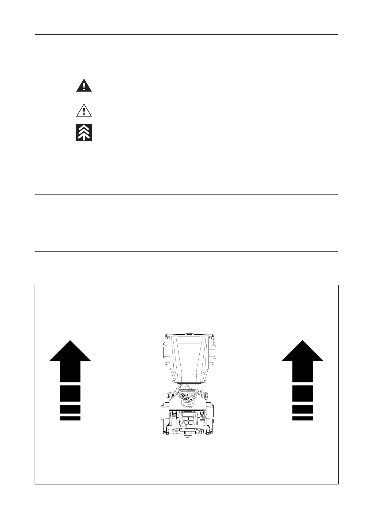
SAFETY NOTICE SIGNS
The notice warns of aserious risk of personal injury or other personal hazards.
The notice warns of possible damage to the machine or its parts.
The notice warns of the necessity of environmental protection.
! CAUTION!
As used in this operating manual, the terms right, left, front and rear indicate sides ofthe machine
moving forward.
LEFT
FRONT
RIGHT
REAR
Page 8

Contents
CONTENTS .......................................................................................................................................................4
1 SPECIFICATION MANUAL ...................................................................................................................... 9
1.1 Basic data ..............................................................................................................................................10
1.2 Dimensional drawing of the machine .................................................................................................12
1.3 Technical data ....................................................................................................................................... 14
2 OPERATING MANUAL ..........................................................................................................................19
2.1 Main safety precautions .......................................................................................................................21
2.1.1 Safety precautions during operation of the machine ..............................................................................................................................21
2.1.1.1 Before compacting works are started ............................................................................................................................................................21
2.1.1.2 Work in the dangerous area ...............................................................................................................................................................................21
2.1.1.3 Ensurance of safety measures bytheprovider ...........................................................................................................................................22
2.1.1.4 Protective ROPS frame .........................................................................................................................................................................................22
2.1.2 Requirements for the qualication ofmachine operators ......................................................................................................................23
2.1.3 Driver's obligations ...............................................................................................................................................................................................24
2.1.4 Forbidden activities – safety andguarantee ................................................................................................................................................25
2.1.5 Safety notices and signs applied on the machine ....................................................................................................................................27
2.1.6 Hand signals ............................................................................................................................................................................................................31
4 ARX 23-2 T4i, ARX 26-2 T4i
Page 9

OPERATING MANUAL
2.2 Environmental and hygiene principles ...............................................................................................34
2.2.1 Hygiene principles ................................................................................................................................................................................................34
2.2.2 Environmental principles ....................................................................................................................................................................................34
2.3 Preservation and storage .....................................................................................................................35
2.3.1 Short-term preservation and storage for1–2 months .............................................................................................................................35
2.3.2 Preservation and storage of the machine for aperiod over 2 months...............................................................................................35
2.3.3 Machine depreservation ..................................................................................................................................................................................... 37
2.4 Machine disposal after its service life .................................................................................................39
2.5 Machine description .............................................................................................................................40
2.6 Controls and checking instruments ....................................................................................................42
2.6.1 Dashboard and control panels .........................................................................................................................................................................43
2.7 Machine operation and use .................................................................................................................60
2.7.1 Starting the engine ............................................................................................................................................................................................... 61
2.7.2 Drive and reverse drive ........................................................................................................................................................................................65
2.7.3 Stopping the machine and turning o the engine ..................................................................................................................................73
2.7.4 Machine emergency stop .................................................................................................................................................................................. 73
2.7.5 Machine parking .................................................................................................................................................................................................... 75
2.7.6 Panic response ........................................................................................................................................................................................................75
2.7.7 Sprinkling ..................................................................................................................................................................................................................77
2.7.8 ACE Force (optional equipment) ......................................................................................................................................................................77
2.7.9 Infrathermometer (optional equipment) ......................................................................................................................................................78
2.7.10 ROPS lifting and lowering ...................................................................................................................................................................................84
2.7.10.1 Lowering and raising of the ROPS frame with a plastic canopy ........................................................................................................... 86
2.7.11 Telematics readiness .............................................................................................................................................................................................92
2.7.12 Edge cutter (optional equipment) ...................................................................................................................................................................93
2.7.13 Calibration mode ...................................................................................................................................................................................................94
2.7.14 Lowering and raising of the plastic canopy .................................................................................................................................................97
2.8 Machine transport ................................................................................................................................ 99
2.8.1 Loading the machine ....................................................................................................................................................................................... 100
2.8.1.1 Loading the machine using aramp ............................................................................................................................................................. 100
2.8.1.2 Loading the machine using acrane ............................................................................................................................................................. 101
2.9 Special conditions to use the machine .............................................................................................102
2.9.1 Towing the machine .......................................................................................................................................................................................... 102
2.9.2 Drum oset .......................................................................................................................................................................................................... 104
2.9.3 Machine operation during initial run period ............................................................................................................................................ 105
2.9.4 Machine operation at low temperatures....................................................................................................................................................105
2.9.5 Machine operation at higher temperatures and humidity ................................................................................................................. 105
2.9.6 Machine operation at higher altitudes ...................................................................................................................................................... 105
2.9.7 Machine operation in dusty environment ................................................................................................................................................. 106
2.9.8 Driving with vibration on compacted and hard materials ................................................................................................................. 106
5ARX 23-2 T4i, ARX 26-2 T4i
Page 10

Contents
3 MAINTENANCE MANUAL ..................................................................................................................107
3.1 Safety and other measures during maintenance of the machine ..................................................109
3.1.1 Safety during machine maintenance .......................................................................................................................................................... 109
3.1.2 Fire protection when operating uids are changed .............................................................................................................................. 109
3.1.3 Environmental and hygiene principles ....................................................................................................................................................... 110
3.2 Specication of operating uids .......................................................................................................111
3.2.1 Engine oil .............................................................................................................................................................................................................. 111
3.2.2 Fuel ........................................................................................................................................................................................................................... 112
3.2.3 Coolant ................................................................................................................................................................................................................... 113
3.2.4 Hydraulic oil .......................................................................................................................................................................................................... 114
3.2.5 Lubricating grease .............................................................................................................................................................................................. 114
3.2.6 Emulsion ................................................................................................................................................................................................................ 114
3.3 Fluids ...................................................................................................................................................115
3.4 Lubrication and maintenance chart ..................................................................................................116
3.5 Lubrication and service plan .............................................................................................................118
3.6 Lubrication and maintenance operations ........................................................................................119
Every 20 hours of operation (daily)
3.6.1 Fuel check .............................................................................................................................................................................................................. 120
3.6.2 Engine oil check .................................................................................................................................................................................................. 121
3.6.3 Engine coolant check ........................................................................................................................................................................................ 122
3.6.4 Checking the oil in the hydraulic tank ........................................................................................................................................................ 123
3.6.5 Cleaning the hydraulic oil cooler .................................................................................................................................................................. 124
3.6.6 Air lter check ...................................................................................................................................................................................................... 125
3.6.7 Sprinkling emulsion level check .................................................................................................................................................................... 126
3.6.8 Sprinkling tank relling .................................................................................................................................................................................... 127
3.6.9 Scraper adjustment ............................................................................................................................................................................................ 127
3.6.10 Inspection of warning and checking devices ........................................................................................................................................... 128
3.6.11 Engine leakage check ........................................................................................................................................................................................ 130
3.6.12 Check of the fan and engine belt for condition ....................................................................................................................................... 130
3.6.13 Brake test ............................................................................................................................................................................................................... 131
3.6.13.1 Check of the parking brake ............................................................................................................................................................................. 131
3.6.13.2 Check of the emergency brake ...................................................................................................................................................................... 132
3.6.13.3 Check of the service brake ............................................................................................................................................................................... 133
3.6.14 Check of the tightness of the fuel andhydraulic system ..................................................................................................................... 134
...................................................................................................120
Every 50 hours of operation ..............................................................................................................135
3.6.15 Check of hoses and clips .................................................................................................................................................................................. 135
3.6.16 Battery inspection .............................................................................................................................................................................................. 136
Every 100 hours of operation ............................................................................................................137
3.6.17 Air lter cleaning ................................................................................................................................................................................................. 137
3.6.18 Cleaning the water separator on the fuel lter ........................................................................................................................................ 138
3.6.19 Machine lubrication ........................................................................................................................................................................................... 139
3.6.20 Tyre pressure check ............................................................................................................................................................................................ 140
6 ARX 23-2 T4i, ARX 26-2 T4i
Page 11

OPERATING MANUAL
Every 250 hours of operation ............................................................................................................141
3.6.21 Fuel lter replacement ...................................................................................................................................................................................... 141
3.6.22 Engine oil change ............................................................................................................................................................................................... 142
3.6.23 Checking the hoses of the engine cooler for wear and mounting ................................................................................................... 144
3.6.24 Checking the hoses and clips for mounting ............................................................................................................................................. 144
3.6.25 Sprinkling lter cleaning .................................................................................................................................................................................. 145
3.6.26 Engine intake pipe inspection ....................................................................................................................................................................... 146
Every 500 hours of operation, but at least once a year ...................................................................147
3.6.27 Fuel tank cleaning............................................................................................................................................................................................... 147
3.6.28 Electrical installation inspection ................................................................................................................................................................... 148
3.6.29 Replacement of the fuel separator lter cartridge ................................................................................................................................. 148
3.6.30 Valve clearance check and adjustment .......................................................................................................................................................149
3.6.31 Engine cooler cleaning ..................................................................................................................................................................................... 149
3.6.32 Check of rubber-metal elements oftheengine cooler ......................................................................................................................... 150
Every 1000 hours of operation ..........................................................................................................151
3.6.33 Hydraulic oil change and lter replacement ............................................................................................................................................. 151
3.6.34 Replacement of air lter cartridges .............................................................................................................................................................. 153
3.6.35 Damping system check .................................................................................................................................................................................... 155
3.6.36 Swinging support check .................................................................................................................................................................................. 156
3.6.37 Articulation joint check ................................................................................................................................................................................... 156
Every 2000 hours of operation ..........................................................................................................157
3.6.38 Engine belt replacement .................................................................................................................................................................................. 157
3.6.39 Engine coolant change .................................................................................................................................................................................... 157
3.6.40 Replacement of hoses of the cooling system ........................................................................................................................................... 159
3.6.41 Replacement of rubber-metal elements of the engine cooler ........................................................................................................... 159
3.6.42 Replacement of hoses of the fuel system .................................................................................................................................................. 160
3.6.43 Replacement of suction hoses ....................................................................................................................................................................... 160
Maintenance as required ...................................................................................................................161
3.6.44 Gas strut replacement ...................................................................................................................................................................................... 161
3.6.45 Cleaning the water separator ......................................................................................................................................................................... 162
3.6.46 Cleaning the water tank ................................................................................................................................................................................... 162
3.6.47 Cleaning the machine ....................................................................................................................................................................................... 163
3.6.48 Draining water from the sprinkling circuit before the winter season ..............................................................................................164
3.6.49 Fuel system venting ........................................................................................................................................................................................... 164
3.6.50 Charging of the battery .................................................................................................................................................................................... 166
3.6.51 Checking the screw connections for tightening ..................................................................................................................................... 167
3.7 Troubleshooting .................................................................................................................................169
3.7.1 List of error codes displayed on the display .............................................................................................................................................. 170
7ARX 23-2 T4i, ARX 26-2 T4i
Page 12

Contents
3.8 Appendices .........................................................................................................................................178
Wiring diagram ..................................................................................................................................................................................................................... 178
Hydraulic diagram ARX 23-2 T4i, ARX 26-2 T4i
Hydraulic diagram ARX 23-2C, ARX 26-2C
Table of spare parts for regular maintenance
Content of the lter set after 250 hours (4-760243)
Content of the lter set after 500 hours (4-760244)
Content of the lter set after 1000 hours (4-760245)
.......................................................................................................................................................... 184
.................................................................................................................................................................. 186
........................................................................................................................................................... 188
................................................................................................................................................ 189
................................................................................................................................................ 189
............................................................................................................................................. 189
8 ARX 23-2 T4i, ARX 26-2 T4i
Page 13

SPECIFICATION MANUAL
1 SPECIFICATION MANUAL
ARX 23-2
ARX 26-2
(Kubota Tier 4i)
9ARX 23-2 T4i, ARX 26-2 T4i
Page 14
4145
588001
1.1 Basic data
Machine description
Tandem machine with an articulated frame and two smooth
drums. Both drums are hydrostatic-driven and vibrating. The
rear drum vibration is switchable. The concept of the frame allows compacting close to the walls and elevated kerbs on both
sides of the machine. It is convenient for works within constrained areas due to its small dimensions and short turning radius. The operator’s post provides perfect control of both edges
of the drums.
Combined machines have only afront smooth vibrating drum.
The rear axle consists of tyres with smooth shoes (compactor).
Specication of the expected use of the machine
Please ll in the following data:
(see nameplate and Kubota engine nameplate)
Machine type
................................................................................................................
Product Identication Number
................................................................................................................
Year of manufacture
The machine is designed for small compaction works in road
construction (building local roads, cycle paths, pavements,
parking areas and garage driveways) and in building construction (small industrial areas).
The machine is suitable for compacting asphalt mixes up to the
(compacted) layer thickness of 120mm (4.7"), hydraulically consolidated mixtures up to the layer thickness of 150mm (5.9"),
mixed soils up to the layer thickness of 200mm (7.9") or sandy
and gritty materials up to the layer thickness of 300mm (11.8").
The machine is not suitable for compacting rock ll, loam and
clay materials.
The machines are designed for operation in arid, temperate and
cold climates according to EN 60721-2-1:2014 with a limited
temperature range from -15 °C (5 °F) to +45 °C (113 °F) and a
maximum absolute humidity of 25 g.m
-3
. Storage temperature
from -25°C (-12°F) to + 45°C (113°F).
The standard version of the machine is not designed for operation on roads. For more information, please contact your dealer.
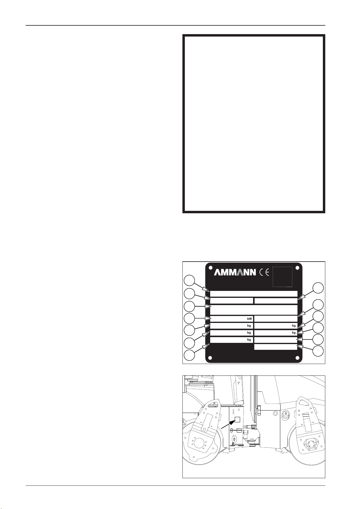
The machine that complies with the requirements as to health
protection and safety is provided with anameplate with CE certication.
1. Name – always mentioned only in the English version
2. Type
3. Product identication number
4. Rated power
5. Operating weight
6. Maximum weight
7. Shipping weight
8. Version
9. Engine emissions
10. Front axle load
11. Rear axle load
12. Year of manufacture
13. Model year
................................................................................................................
Engine type
................................................................................................................
Serial number of the engine
................................................................................................................
The data mentioned in the table refer always when you contact
the dealer or manufacturer.
4145
AMMANN CZECH REPUBL IC a.s.
1
2
3
4
5
6
7
549 01 NOVÉ MĚSTO NAD METUJ Í, Náchodská 145
CZECH REPUBLIC
DESIGN ATION
TYPE
PRODUC T IDENT IFICATION NUMBER
NOMINA L POWER
OPERATIN G MASS
MAXIMU M MASS
SHIPPI NG MASS
MADE IN CZECH RE PU BL IC
VERSIO N
ENGINE EMISSI ONS
FRONT AX LE LOAD
REAR AXL E LOAD
YEAR OF CONSTR UCTION
MODEL YE AR
8
9
10
11
12
13
Nameplate position
Nameplate
10 ARX 23-2 T4i, ARX 26-2 T4i
Page 15
588002
588003
593077
588094
SPECIFICATION MANUAL
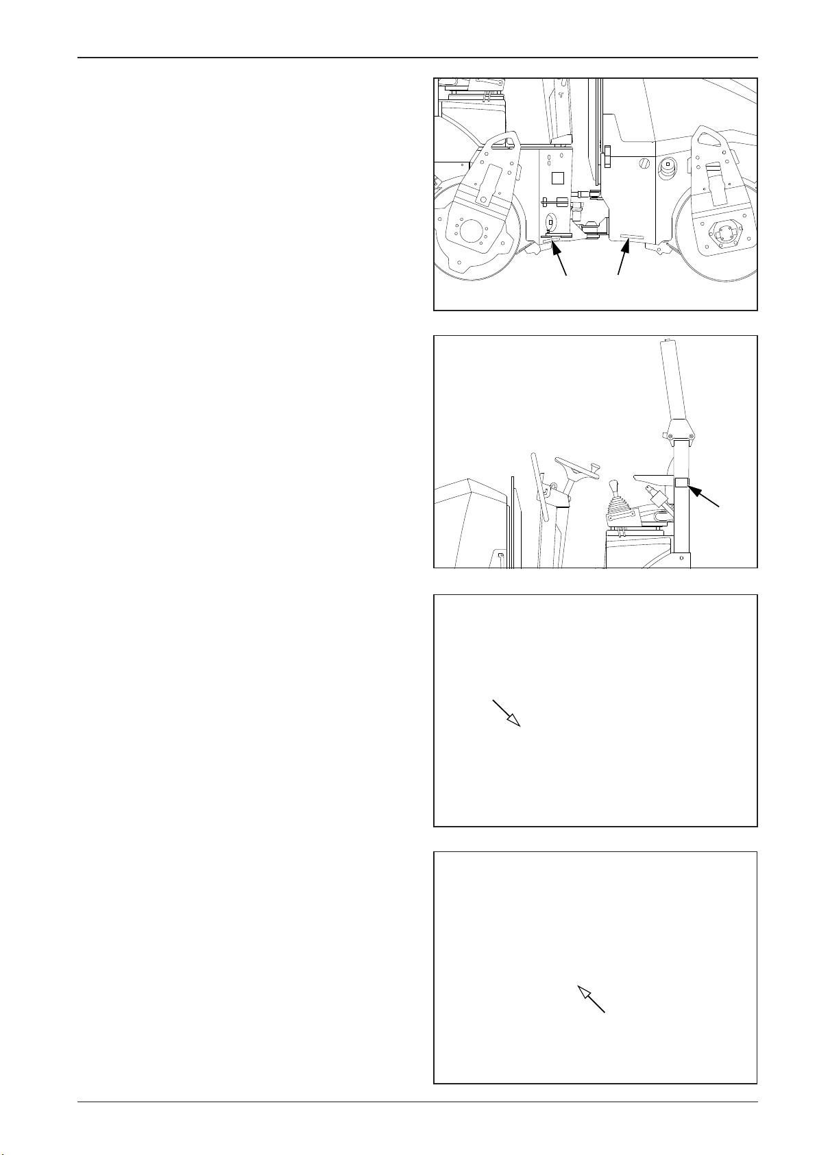
Serial number of the machine frame
Position of the ROPS nameplate
ROPS nameplate
Engine nameplate position
Serial number of the Kubota engine
11ARX 23-2 T4i, ARX 26-2 T4i
Page 16
588004A
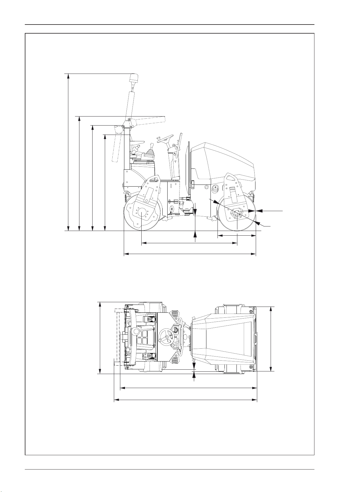
1.2 Dimensional drawing of the machine
H
H2
H3
H1
L2
T
G
D
A
D
W1
X
L
L2
W
12 ARX 23-2 T4i, ARX 26-2 T4i
Page 17
588611
SPECIFICATION MANUAL
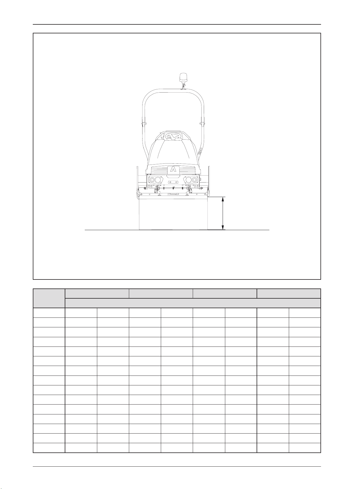
G1
mm (in)
A 1740 (68.5) 1755 (69.1) 1740 (68.5) 1755 (69.1)
D 695 (27.4) 695 / 635 (27.4 / 25) 695 (27.4) 695 / 635 (27.4 / 25)
G 280 (11.0) 280 (11.0) 280 (11.0) 280 (11.0)
G1 490 (19.3) 490 (19.3) 490 (19.3) 490 (19.3)
H 2550 (100.4) 2550 (100.4) 2550 (100.4) 2550 (100.4)
H1 1815 (71.5) 1815 (71.5) 1815 (71.5) 1815 (71.5)
H2 2140 (84.3) 2140 (84.3) 2140 (84.3) 2140 (84.3)
H3 1935 (76.2) 1935 (76.2) 1935 (76.2) 1935 (76.2)
L 2500 (98.4) 2500 (98.4) 2500 (98.4) 2500 (98.4)
L1 2585 (101.8) 2585 (101.8) 2585 (101.8) 2585 (101.8)
L2 2430 (95.7) 2420 (95.3) 2430 (95.7) 2420 (95.3)
W 1000 (39.4) 1000 (39.4) 1200 (47.2) 1200 (47.2)
W1 1130 (44.5) 1120 (44.1) 1350 (53.1) 1295 (51.0)
X 40 (1.6) - - 40 (1.6) - -
T 13
ARX 23-2 ARX 23-2C ARX 26-2 ARX 26-2C
EU Stage IIIA / U.S. EPA Tier 4i
(0.5) 13 (0.5) 13 (0.5) 13 (0.5)
13ARX 23-2 T4i, ARX 26-2 T4i
Page 18

1.3 Technical data
ARX 23-2 ARX
23-2C
EU Stage IIIA / U.S. EPA Tier 4i
ARX 26-2 ARX
26-2C
Weight
Operating weight of EN 500-1+A1
(CECE)
Operating load of EN 500-1+A1
(CECE) on front axis
Operating load of EN 500-1+A1
(CECE) on rear axis
Weight of half uid capacities kg (lb) 110 (240) 115 (250) 110 (240) 115 (250)
Operating weight of ISO 6016 kg (lb) 2275 (5020) 2135 (4710) 2475 (5460) 2315 (5100)
Maximum weight with accessories kg (lb) 2495 (5500) 2310 (5090) 2655 (5850) 2500 (5510)
Maximum permitted weight according to ROPS
Static linear load of front drum kg/cm (lb/in) 10.7 (20) 10.7 (20) 9.8 (20) 9.8 (20)
Static linear load of rear drum kg/cm (lb/in) 10.9 (20) - 10.7 (20) -
Weight of Canopy kg (lb) 35 (80) 35 (80) 35 (80) 35 (80)
Weight of Ammann edge cutter kg (lb) 50 (110) 50 (110) 50 (110) 50 (110)
Deduction for the transport weight
to the EN 500-1+A1 (CECE) operating weight.
kg (lb) 2260 (4980) 2110 (4650) 2460 (5420) 2300 (5070)
kg (lb) 1070 (2360) 1070 (2360) 1180 (2600) 1180 (2600)
kg (lb) 1190 (2620) 1040 (2290) 1280 (2820) 1120 (2470)
kg (lb) 2850 (6280) 2850 (6280) 2850 (6280) 2850 (6280)
kg (lb) 180 (400) 185 (410) 180 (400) 185 (410)
Driving characteristics
Maximum transport speed km/h (MPH) 11 (6.8) 11 (6.8) 11 (6.8) 11 (6.8)
Climbing ability without vibration % 35 35 35 35
Climbing ability with vibration % 30 35 30 35
Lateral static stability % 55 46 62 53
Lateral stability during driving without vibration
Lateral stability during driving with
vibration
Turning radius inner (edge) mm (in) 2630 (103.5) 2630 (103.5)
Turning radius outer (contour) mm (in) 3750 (147.6) 3750 (147.6) 3910 (153.9) 3910 (153.9)
Type of drive - Hydrostatic Hydrostatic Hydrostatic Hydrostatic
Number of driving axles - 2 2 2 2
Oscillation angle ° 6.5 6.5 6.5 6.5
Angle of steering ° 30 30 30 30
% 25 20 25 20
% 15 10 15 10
2540 (100) 2540 (100)
Steering
Type of steering - Joint Joint Joint Joint
Steering control - Hydraulic Hydraulic Hydraulic Hydraulic
Linear hydraulic motors - 1 2 1 1
14 ARX 23-2 T4i, ARX 26-2 T4i
Page 19

SPECIFICATION MANUAL
ARX 23-2 ARX
23-2C
EU Stage IIIA / U.S. EPA Tier 4i
ARX 26-2 ARX
26-2C
Engine
Manufacturer - Kubota Kubota Kubota Kubota
Type -
Power according to SAE J1995 kW 24.8 24.8 24.8 24.8
Number of cylinders - 3 3 3 3
Cylinder capacity cm
Nominal speed min
Maximum torque Nm (ft lb)/rpm 115.6 / 1600 115.6 / 1601 115.6 / 1602 115.6 / 1603
Average fuel consumption l/h (gal US/h) 3.1 (0.8) 3.1 (0.8) 3.1 (0.8) 3.1 (0.8)
Engines complies with emission
regulations
Cooling system of engine - Liquid Liquid Liquid Liquid
3
(cu in) 1826 (111) 1826 (111) 1826 (111) 1826 (111)
-1
(RPM) 2100 / 2400 2100 / 2400 2100 / 2400 2100 / 2400
-
D1803-M-DI-
E3B
EU Stage IIIA, U.S.
EPA Tier 4 Interim
D1803-M-DI-
E3B
EU Stage IIIA, U.S.
EPA Tier 4 Interim
D1803-M-DI-
E3B
EU Stage IIIA, U.S.
EPA Tier 4 Interim
D1803-M-DI-
E3B
EU Stage IIIA, U.S.
EPA Tier 4 Interim
Brakes
Operating - Hydrostatic Hydrostatic Hydrostatic Hydrostatic
Parking -
Emergency -
Mechanical
multiple-disc
Mechanical
multiple-disc
Mechanical
multiple-disc
Mechanical
multiple-disc
Mechanical
multiple-disc
Mechanical
multiple-disc
Mechanical
multiple-disc
Mechanical
multiple-disc
Vibration
Frequency I Hz (VPM) 58 (3480) 58 (3480) 58 (3480) 58 (3480)
Frequency II Hz (VPM) 66 (3960) 66 (3960) 66 (3960) 66 (3960)
Amplitude I mm (in) 0.5 (0.02) 0.5 (0.02) 0.5 (0.02) 0.5 (0.02)
Amplitude II mm (in) 0.5 (0.02) 0.5 (0.02) 0.5 (0.02)
Centrifugal force I kN 33.4 33.4 38.8 38.8
Centrifugal force II kN 39.9 39.9 46.5 46.5
Type of drive - Hydrostatic Hydrostatic Hydrostatic Hydrostatic
0.5 (0.02)
Watering
Type of watering - Pressure Pressure Pressure Pressure
Number of pumps - 1 1 1 1
Number of ltrations - 2 2 2 2
Fluid capacities
Fuel l (gal US) 35 (9.2) 35 (9.2) 35 (9.2) 35 (9.2)
Water for drum watering l (gal US) 190 (50.2) 190 (50.2) 190 (50.2) 190 (50.2)
Engine (oil lling) l (gal US) 7 (1.8) 7 (1.8) 7 (1.8) 7 (1.8)
Cooling system l (gal US) 6.7 (1.8) 6.7 (1.8) 6.7 (1.8) 6.7 (1.8)
Hydraulic system l (gal US) 28.5 (7.5) 28.5 (7.5) 28.5 (7.5) 28.5 (7.5)
Wiring
Voltage V 12 12 12 12
Battery capacity Ah 77 77 77 77
15ARX 23-2 T4i, ARX 26-2 T4i
Page 20

1.3 Technical data
Noise and vibration emissions
Measured sound pressure level
A, LpA at the operator's position
(platform) *
Uncertainty K
* dB 2 2 2 2
pA
Guaranteed sound power level A,
L
**
WA
Highest weighted eective value of
acceleration of vibrations transmitted to the whole body (platform) ***
Total value of acceleration of vibrations transmitted to hands (platform) ***
Optional equipment
Additional lights
Direction indicators
Working lights
Beacon
Back signal horn
Licence plate holder
One-point lifting lug
Battery disconnector
nd
travel control lever
2
Arm rest
Water tank lock
Infra thermometer
ACE Force
ATC inter-axle lock
Edge cutter
Fixed scrapers
Hinged scrapers
Set of lters, 500 h
FOPS roof (mounted on the ROPS)
Canopy
Seat heating
Special colour design
Additional documentation set
Certicate of Origin
Audible brake warning
Rear-view mirrors
Telematic
Green LED beacon
Plastic roof
ARX 23-2 ARX
23-2C
ARX 26-2 ARX
EU Stage IIIA / U.S. EPA Tier 4i
dB 85 85 85 85
dB 104 104 104 104
2
(ft/s2) <0.5 (<1.6) <0.5 (<1.6) <0.5 (<1.6) <0.5 (<1.6)
m/s
2
(ft/s2) <2.5 (<8.2) <2.5 (<8.2) <2.5 (<8.2) <2.5 (<8.2)
m/s
26-2C
* measured according to EN 500-4
** measured according to DIRECTIVE 2000/14/EC
*** measured according to EN 1032+A1 while driving with vibration on gravel foundation
16 ARX 23-2 T4i, ARX 26-2 T4i
Page 21

SPECIFICATION MANUAL
Notes
17ARX 23-2 T4i, ARX 26-2 T4i
Page 22

18 ARX 23-2 T4i, ARX 26-2 T4i 19ARX 23-2 T4i, ARX 26-2 T4i
Page 23

OPERATING MANUAL
2 OPERATING MANUAL
ARX 23-2
ARX 26-2
(Kubota Tier 4i)
Page 24

20 ARX 23-2 T4i, ARX 26-2 T4i 21ARX 23-2 T4i, ARX 26-2 T4i
Page 25

OPERATING MANUAL2.1 Main safety precautions
2.1.1 Safety precautions during operation of the machine
Safety measures given in the individual chapters of the technical documentation supplied with the machine must be supplemented with safety precautions in the workplace in force
within the respective country where the machine is used, with
respect to organization of work, working process and personnel
involved.
2.1.1.1 Before compacting works are started
• The building contractor (machine user) is liable to issue
instructions for operators and maintenance workers that
include requirements to provide for safe operation of the
machine.
• Before the compacting works are started, he must verify:
- utility lines
- underground areas (direction, depth)
- seepage or sudden escape of harmful substances
- ground-bearing capacity, travel plane slope
- other obstacles and specify work safety measures.
He must make the machine operator carrying out the earth
works familiar with the above items.
• He must specify atechnological procedure including awork-
ing process for the specic job that species among others:
- measures for works under extraordinary conditions
(works within protection zones, extreme slopes, etc.)
- precautions for any natural disaster hazards
- work performance requirements and observance of
principles of health and safety at work
- technical and organizational measures to ensure safety
of employees, workplaces and surroundings.
He must make the machine operators provably familiar with
the technological procedure.
2.1.1.2 Work in the dangerous area
Any damage to the utility lines must be immediately reported
to their provider, and at the same time measures must be taken
to prevent unauthorized persons from entering the dangerous
area.
The worker is not allowed to work alone in aworkplace where
another worker is not in sight and within an ear shot who if necessary will be able to provide help or call for help unless another
eective form of supervision or communication is ensured.
Page 26

2.1 Main safety precautions
2.1.1.3 Ensurance of safety measures
bytheprovider
• He must ensure that the machine is operated only under
conditions and only for purposes it is technically capable of
according to conditions specied by the manufacturer and
respective standards.
• He must ensure that the machine is used only in such away
and in such aworkplace where there is no risk of transmission of dangerous vibrations and damage to nearby facilities, etc.
• He must ensure aregular inspection of operation and techni-
cal condition, and regular machine maintenance in intervals
according to the lubrication and maintenance instructions.
If the technical condition of the machine does not meet requirements to such an extent that the machine endangers
safety of operation, persons and property, or damages and
impairs the environment, it must be put out of service until
the defects are removed.
• He must specify who is allowed to carry out operation, main-
tenance and repairs of the machine as well as what activities
can be carried out in such cases.
• Every person who drives the machine or performs mainte-
nance and repairs of the machine must be familiarised with
instructions stated in the operating manual of the machine.
• He must ensure that the re extinguisher is checked on
regular basis.
• He must ensure that the "Operating manual" is available at
adesignated location in the machine.
• He must ensure continuous supervision by an appointed
person during machine operation on public roads and is liable in particular for releasing instructions to ensure health
protection and work safety.
• He must ensure that dangerous substances (fuel, oils, cool-
ant, etc.) must be removed from places of leakage according
to their nature to avoid their adverse impact on the environment, safety of operation and human health.
2.1.1.4 Protective ROPS frame
When the ROPS protection frame is used:
• the machine frame must not be damaged (broken, bent,
etc.) in the connection point
• the protective ROPS frame itself must not show corrosion,
cracks or breaks
• the protective ROPS frame must not be loose during opera-
tion of the machine
• all bolted connections must meet requirements of the spec-
ication and must be tightened to the specied torque
• bolts must not be damaged, distorted and must not show
rust marks.
• Additional modications must not be carried out on the
protective ROPS frame without the approval of the manufacturer because they can result in decrease of its strength
(e.g. holes, welding, etc.).
• The machine weight must not exceed the maximum permis-
sible weight according to the protective ROPS frame.
22 ARX 23-2 T4i, ARX 26-2 T4i
Page 27

OPERATING MANUAL
2.1.2 Requirements for the qualication
ofmachine operators
Only aperson having been trained according to ISO 7130 and
other local and national instructions and standards specied for
operators of this group of machines, is allowed to operate the
machine.
23ARX 23-2 T4i, ARX 26-2 T4i
Page 28

2.1 Main safety precautions
2.1.3 Driver's obligations
• Before starting operation of the machine, the machine op-
erator is obliged to get familiar with instructions stated in
the documentation supplied together with the machine,
especially with safety precautions, and strictly observe
the instructions. This also applies to personnel assigned to
maintain, adjust and repair the machine. (In case you do not
understand some parts of the manuals, contact the nearest
dealer or the manufacturer.)
• He may drive the machine only if he is fully familiarized with
all functions of the machine and working and operating elements and knows precisely how to operate the machine.
• The driver is obliged to follow the safety signs located on the
machine and keep them legible.
• Before starting the work, the operator must get familiar with
the workplace environment, i.e. with obstructions, slopes,
utility line system and with necessary types of workplace
protections with respect to the surroundings (noise, vibration, etc.).
• The operator while working with the machine must be fas-
tened with the safety belt.
• The safety belt and its brackets must not be damaged.
• When there is arisk to health, human life, property, failures,
during hardware accidents, or there are symptoms of such
risks during operation, the operator must stop his work and
secure the machine against undesired starting, communicate this to aresponsible worker and to apossible extent
notify all the persons exposed to such hazard.
• Before starting operation of the machine, the operator is
obliged to get familiar with the records and operating deviations found out during the previous work shift.
• Before starting the work, the driver is obliged to inspect the
machine and accessories and to check control elements and
communication and safety equipment for functioning according to the manual. If he nds adefect that might endanger the safety of work and is not able to repair it, then he
must not put the machine into operation and must report
the defect to aresponsible worker.
• If the operator nds adefect during operation, he must im-
mediately stop the machine and secure it safely against undesirable starting.
• During operation the operator must watch the machine run
and record any detected defects into the operation logbook.
• The operator must maintain an operation logbook which is
meant for records of machine acceptances and take-overs
carried out between operators, of defects and repairs done
during operation and keeping les of serious events during
the work shift.
• Before putting the machine into operation, he must check
the brakes and steering for functioning.
• Before the engine is put into operation, both travel controls
must be in the parking position (P); no persons are allowed
to stay within dangerous reach of the machine.
• The driver must always notify the others each time the ma-
chine is put into operation with the help of asound or light
signal before starting the engine of the machine.
• After awarning alarm, the operator may put the machine
into operation only when all workers have left the endangered area. During operation of the machine it is necessary
to follow safety instructions and not to carry out any activity
that might endanger the work safety; the operator must be
fully engaged in driving the machine. He must always sit on
the seat while driving the machine.
• The driver must comply with technological procedures of
works or instructions of aresponsible worker.
• When rolling (traversing) the machine within the workplace,
he must adapt the driving speed to terrain conditions, the
work performed and weather conditions. He must watch
continuously the clearance to avoid collision with any obstruction.
• If the operator nishes or interrupts operation of the ma-
chine and leaves the machine, he must carry out safety
measures against unauthorized use of the machine and undesired start up. The operator must remove the key from the
ignition box, lock the cab or dashboard cover and disconnect the electrical installation using the disconnector.
• When the operation is completed, park the machine at
asuitable parking place (at, bearing surface) so as not to
endanger stability of the machine; the machine must not
interfere with trac roads, must not be exposed to falling
objects (rocks), and must be protected against any natural
disaster of another kind (oods, landslides, etc.).
• When parking the machine on roads, the measures accord-
ing to road trac regulations shall be taken. The machine
must be marked properly.
• After nishing the work with the machine, all of the defects,
damages to the machine and any repairs made must be recorded in the operation logbook. When the operators take
turns, one operator is obliged to report any identied facts
to the other operator.
• The operator must use personal protective equipment –
work clothes, work shoes, protective helmet and protective
goggles.
• He must equip the machine with accessories and equip-
ment as prescribed.
• He must keep the operator’s stand, foot rests and walkways
clean.
• Keep the machine free of oil contaminants and inammable
materials.
• If the machine could come into contact with high voltage,
the following principles must be observed:
- try to leave the hazardous zone with the machine;
- do not leave the operator’s stand;
- warn the others to keep o and not touch the machine.
24 ARX 23-2 T4i, ARX 26-2 T4i
Page 29

OPERATING MANUAL
2.1.4 Forbidden activities – safety
andguarantee
The following is forbidden
• Using the machine in case of an evident defect of the ma-
chine.
• Using the machine when any of the operating uid levels
is low.
• To repair the engine without authorization – except com-
mon changes of operating uids and lters, only an authorized service organization is allowed to intervene in the
engine, including the peripheral components of the engine
(for example, the alternator, the starter, the thermostat, the
electrical installation of the engine.
• Increasing and decreasing the engine speed rapidly; you
could damage the engine.
• Using the emergency brake for turning o the engine dur-
ing normal operation of the machine.
• Operate the machine in potentially explosive atmospheres
(ATEX) and underground areas.
• Using the machine after ingestion of alcoholic beverages or
drugs.
• Using the machine if its operation might endanger its tech-
nical condition, safety (life, health) of persons, facilities or
objects, or road trac and its continuity.
• Putting the machine into operation and using the machine
when other persons are within its danger zone – the exception is atraining of adriver by an instructor.
• Putting the machine into operation and using the machine
when a safety device (emergency brake, hydraulic locks,
etc.) has been removed or damaged.
• Travelling and compacting in such slopes where the ma-
chine stability would be broken (overturning). The stated
machine static stability is reduced by dynamic eects of the
drive.
• Travelling and compacting in such gradients of slopes
where there is arisk of soil breaking o (dropping) under
the machine or of loss of adhesion and of uncontrolled slip.
• Controlling the machine in some other way than stated in
the operating manual.
• Travelling and compacting with vibration according to the
bearing capacity of the subsoil in such adistance from the
slope edge or trenches where there is arisk of landslide or
shoulder breaking o (dropping) together with the machine.
• Travelling and compacting with vibration in such adistance
from walls, cuts and slopes where there is arisk of landslide
and the machine could be covered up with soil.
• Compacting with vibration in such adistance from build-
ings or facilities and equipment within which there is arisk
of damage due to transmission of vibration.
• Moving and transporting persons on the machine.
• Working with the machine if the operator´s stand is not
properly attached.
• Working with the machine when the bonnet, cab or plat-
form is lifted o.
• Working with the machine if there are other machines or
means of transport in its danger zone, except those that operate in mutual cooperation with the machine.
• Working with the machine at aplace that is not seen from
the operator’s stand and where hazard to people or property could occur unless the occupational safety is ensured
through some other way, e.g. by aduly instructed signalling
person.
• Working with the machine in aprotected zone of electric
lines or substations.
• Crossing electric cables if they are not properly protected
against mechanical damage.
• Working with the machine in reduced visibility or at night
unless the machine’s working area and the workplace are illuminated suciently.
• Leaving the seat of the machine operator when the machine
is running.
• Getting in or o on the run, jumping down from the ma-
chine.
• Sitting on the railing or external parts of the machine during
adrive.
• Leaving the machine unattended – moving away from the
machine without having prevented its misuse.
• Disabling safety, protective or locking systems or altering
their parameters.
• Using amachine from which oil, fuel, coolant or other oper-
ating uid is leaking.
• Starting the engine in adierent way than given in the op-
erating manual.
• Placing other items (tools, accessories) than items for per-
sonal use on the operator’s stand.
• Placing materials or other items on the machine.
• Removing dirt while the machine is running.
• Performing maintenance, cleaning or repairs with the ma-
chine not secured against spontaneous movement or accidental start, and if aperson can come in contact with moving parts of the machine.
• Touching moving parts of the machine with the human
body or items and tools held in hands.
• Smoking or handling open re when checking or pumping
fuels, replacing and relling oils, lubricating the machine
and inspecting the battery and relling the battery.
• Conveying rags saturated with inammable materials and
inammable liquids in loose vessels on the machine (in the
engine compartment).
• Leave the engine running in enclosed, unventilated areas.
Exhaust fumes are dangerous to life.
• Performing modications on the machine without the prior
consent of the manufacturer.
• Travelling with the seat belt not fastened.
• Moving electrical conductors.
• Using other than original spare parts.
• Intervening in electrical and electronic units in any manner.
• Using the pressure washing near the control unit of the ma-
chine.
• Filling the hydraulic circuit during the guarantee period in
adierent way than using the hydraulic unit.
• Working long-term in the vibro stroke mode!
Non-observance of the above provisions can impact on
the assessment of acomplaint and eectiveness of the
engine guarantee period.
25ARX 23-2 T4i, ARX 26-2 T4i
Page 30
588005D
2.1 Main safety precautions
16
4
15
6
3
8
18
19
20
16
10
14
2
13
4
8
3
9
5
1
16
16
7
21
22
12
2
17
11
26 ARX 23-2 T4i, ARX 26-2 T4i
Page 31
3865
3864bz
3867bz
3866
OPERATING MANUAL
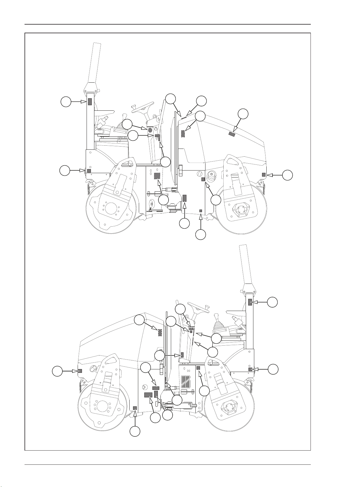
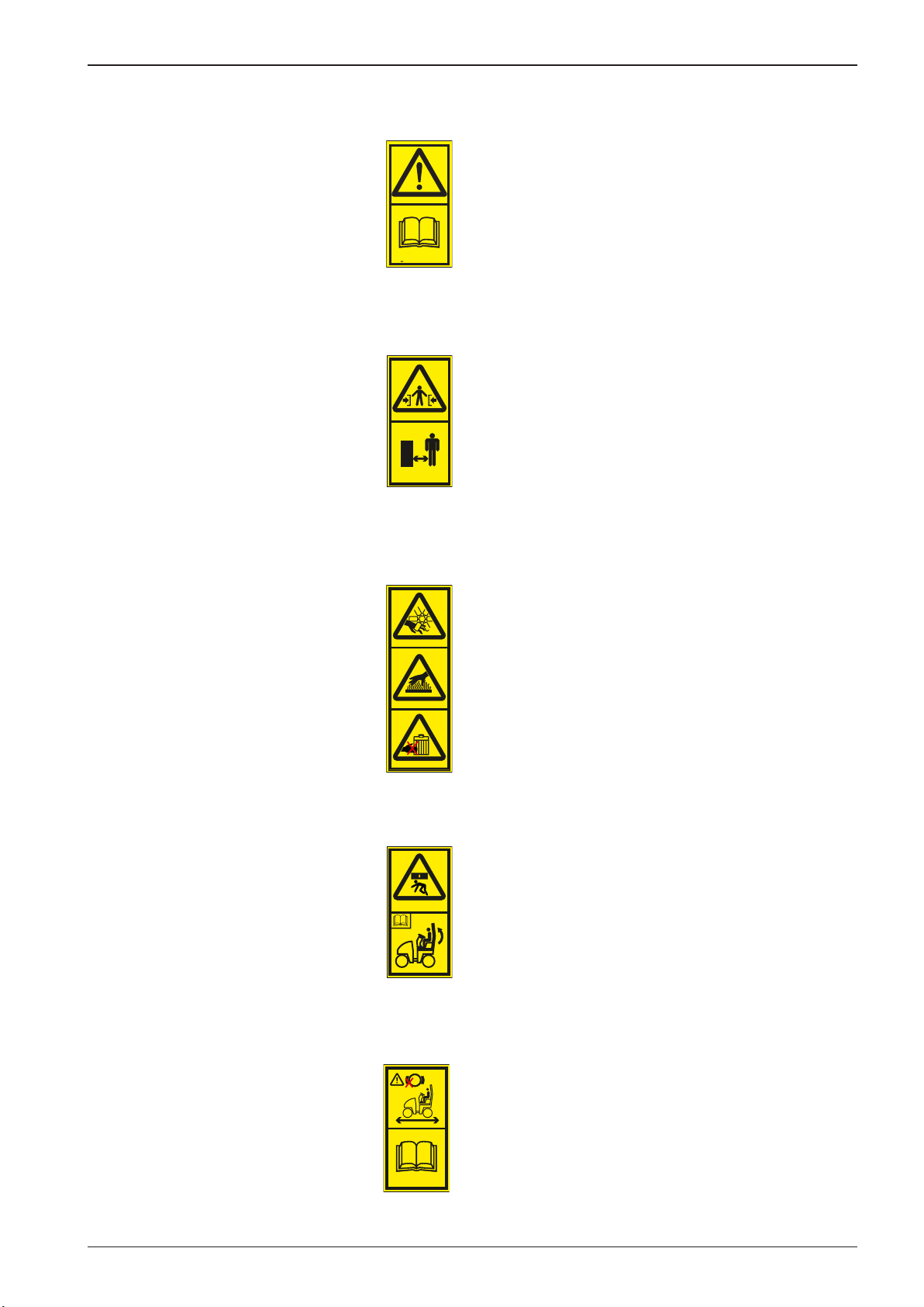
2.1.5 Safety notices and signs applied on the machine
1 Read the operating manual
Get perfectly familiar with the machine operation and
maintenance according to the operating manual!
2946bz
2 Pinch points Maintain asafe distance from the machine; there is adan-
ger of squeezing by the machine between the front and
rear frames.
3865
3 Risk of injury There is arisk of injury. Do not touch rotating parts while
the engine is running. There is a risk of burns. Do not
touch hot parts of the machine unless you make sure that
they are suciently cold.
3866
4 Risk of injury There is arisk of fatal injury. Do not operate the machine
when the ROPS is lowered.
3864
5 Using the parking and emergency brakes Use the parking brake only when the machine is stopped.
P
Use the emergency brake only for stopping the machine
in emergency.
3867
27ARX 23-2 T4i, ARX 26-2 T4i
Page 32
3863bz
2408bz
3567
2584bz
3733
2.1 Main safety precautions
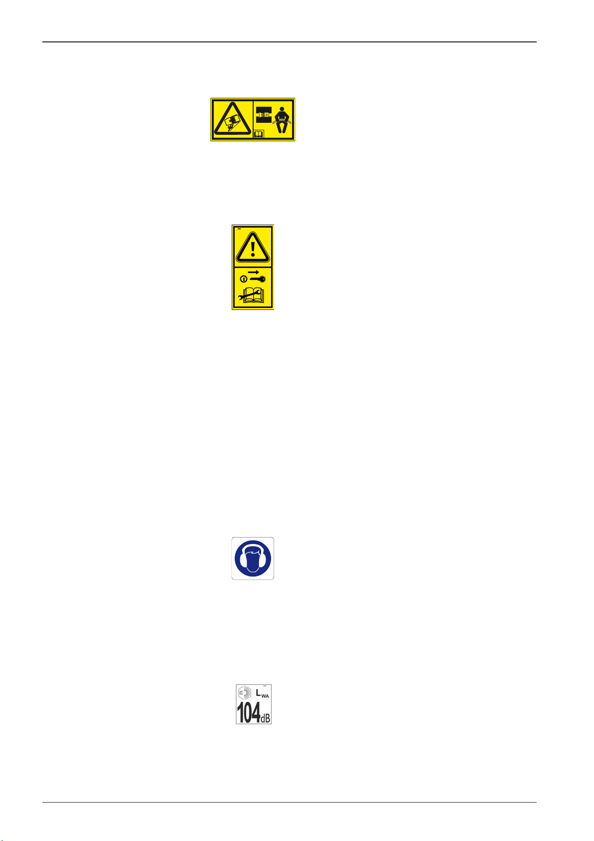
6 Safety belt Fasten the safety belt before the machine starts moving.
3863
2939
7. Keep calm and adjust Turn o the engine and remove the key from the ignition
box before performing maintenance or repairs.
2939
8 Washing the machine with water Dangerous situation. Prevent water from entering elec-
tric and electronic parts of the machine as it may result in
damage of the equipment and personal injury. Read the
operation manual!
9 Hearing protection Dangerous noise level! Use hearing protection.
10 Guaranteed sound power level
28 ARX 23-2 T4i, ARX 26-2 T4i
Page 33
3960
3212
2153bz
3213
2151bz
OPERATING MANUAL
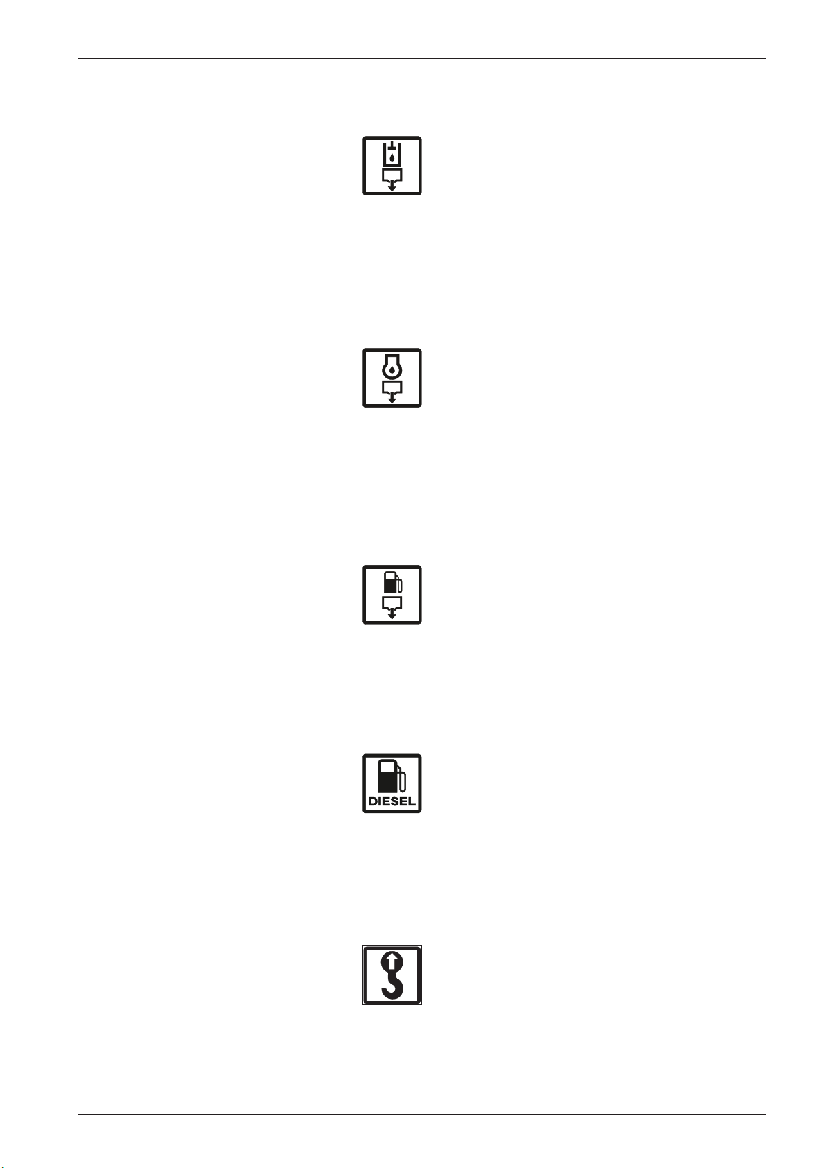
11 Hydraulic oil drain plug
3960
12
Engine oil drain plug
3212
13 Fuel drain plug
3213
2151
14 Fuelling
15 Lifting point When lifting, suspend the machine only in these holes.
29ARX 23-2 T4i, ARX 26-2 T4i
Page 34

3048bz
1227540
4005
4055bz
3518
I II
3868
2.1 Main safety precautions
16 Fastening hole When transporting, fasten the machine only in these
holes.
3747 lb
WLL
17 Suspension diagram To lift the machine, use slings with asucient lifting ca-
18 Set of lters
1700 kg
β
0° ≤ α ≤ 60°
30° ≤ β ≤ 60°
5511 lb
LC
2500 kg
α
pacity according to chapter Loading the machine. Before
hanging, lock the articulation of the machine.
19 Engine speed adjustment
in per cents
85 100
3868
20 Engine speed
2406
0
bz2406
21 California Proposition 65 Exhaust gases and their components, operating uids,
batteries and other machine accessories contain chemicals known in the state of California to be substances
4055
which may cause cancer, congenital defects and other
reproduction problems.
When handling these substances, abide by relevant safety precautions.
Further information see www.p65warnings.ca.gov
22 Emulsion sprinkling tank
30 ARX 23-2 T4i, ARX 26-2 T4i
anti-adhesive
liquid
3518
Page 35
Sig. 10
Sig. 11
OPERATING MANUAL
2.1.6 Hand signals
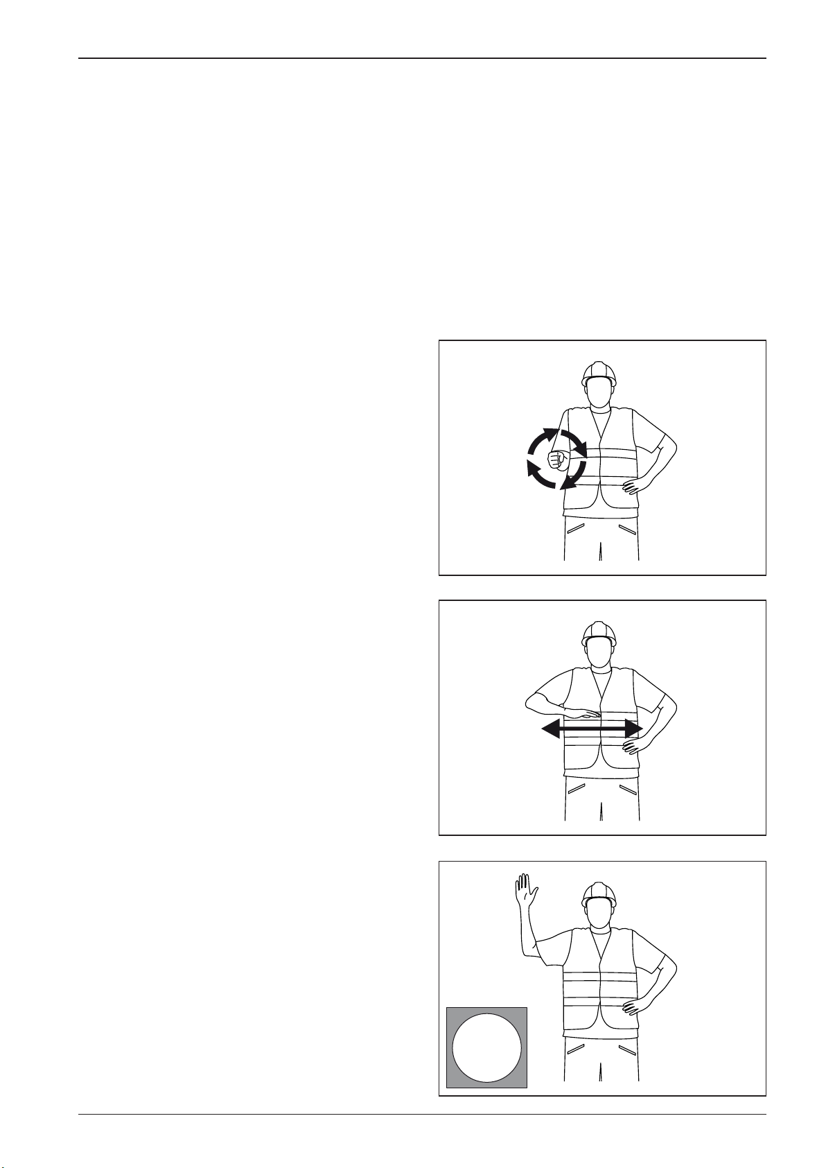
Signals given by an assistant operator if the operator cannot see
the travelling or working area or work devices of the machine.
The following principles must be observed:
• For communication purposes, only alimited number of sig-
nals must be used.
• The signals must be clearly distinguishable to prevent any
misunderstanding.
• Hand signals can only be used when ambient conditions al-
low clear communication between persons.
• Hand signals must be as similar as possible to intuitive
movements.
• Single-handed signals can be done with any hand.
SIGNALS FOR GENERAL COMMANDS
Engine start
Engine OFF
Stop
STOP
Sig. 1
31ARX 23-2 T4i, ARX 26-2 T4i
Page 36
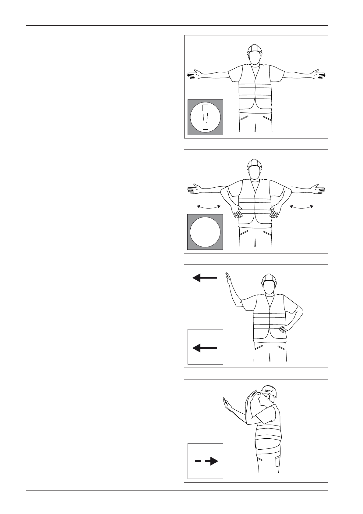
!
Sig. 4
!
2.1 Main safety precautions
Watch out!
Watch out, danger!
Sig. 2
SIGNALS FOR DRIVE
Travel
Slow forward travel – towards me
Sig. 3
32 ARX 23-2 T4i, ARX 26-2 T4i
Sig. 5
Page 37
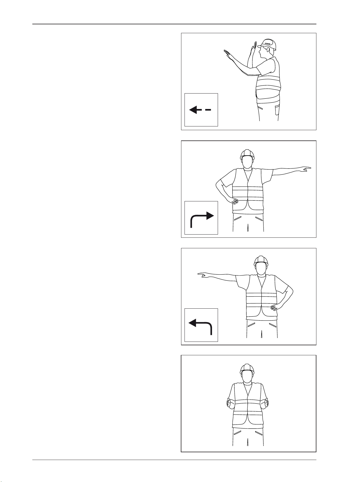
Sig. 6
Sig. 9
Sig. 7
OPERATING MANUAL
Slow reverse travel – away from me
Drive to the right
Drive to the left
Short distance travel
Sig. 8
33ARX 23-2 T4i, ARX 26-2 T4i
Page 38

2.2 Environmental and hygiene principles
2.2.1 Hygiene principles
When operating and storing the machines, the user is
obliged to observe general principles of health and environmental protection, and laws and regulations relating
to the given points at issue within the territory where the
machine is used.
• Petroleum products, cooling system uids, battery uids
and coating compounds including thinners are substances
harmful to health. Workers coming into contact with the
above products during operation or maintenance of the
machine are obliged to follow general principles of their
own health protection and comply with safety and hygienic
manuals made by manufacturers of the products.
In particular we draw your attention to the following:
- protect your eyes and skin while working with the batteries
- protect your skin while handling petroleum products,
coating compounds and coolants
- wash your hands properly after nishing the work and
before eating, treat your hands with asuitable reparation cream
- when handling cooling systems, follow instructions given in the manuals supplied with the machine.
• Always store petroleum products, cooling system uids, bat-
tery cartridges and coating compounds including organic
thinners, and also cleaners and preserving agents in original
and properly labelled containers. These materials are not allowed to be stored in unlabelled bottles or in any other containers considering the possible risk of confusion. Possible
confusion with foodstus or beverages is very dangerous.
• If by accident the skin, eyes or mucous membrane is stained
or if you breathe in the vapours of such products, apply immediately the principles of the rst aid. In case of accidental
ingestion of these products, immediately seek medical help.
• When working with a machine that is not provided with
acab or when the cab windows are open, always use ear
protectors of suitable type and version.
2.2.2 Environmental principles
• Discarded operating uids of individual systems of the ma-
chine and also some of its parts become hazardous wastes
with dangerous properties for the environment.
This category of waste products includes in particular:
- organic and synthetic lubricating materials, oils and fuels;
- coolants;
- battery uids and batteries;
- cleaning and preservative agents;
- all dismounted lters and lter cartridges,
- all used and discarded hydraulic or fuel hoses, rubbermetal elements and other parts of the machine contaminated by the above mentioned products.
It is necessary to treat the above mentioned materials
and parts after they have been discarded in accordance
with relevant national regulations applicable to environmental and health protection.
34 ARX 23-2 T4i, ARX 26-2 T4i
Page 39

2.3 Preservation and storage
2.3.1 Short-term preservation and storage
for1–2 months
Wash and clean the entire machine carefully. Before parking the
machine for preservation and storage, run the engine to warm it
up to its operating temperature. Park the machine on asolid and
at surface at asafe place with no risk of natural disaster (oods,
landslides, re, etc.) for the machine.
In addition:
• repair paints where damaged.
• lubricate all lubrication points
• conrm that water llings are drained
• check that the coolant has the required antifreeze proper-
ties
• check that the batteries are charged and/or recharge them
if necessary
• lubricate chromed surfaces of piston rods with preservative
grease
• We recommend you to protect the machine against corro-
sion with apreservative coating (applied by spraying), especially where corrosion can occur.
2.3.2 Preservation and storage of the
machine for aperiod over 2 months
For machine shut-down, the same principles are applicable as
for the short-term preservation.
In addition it is recommended to:
• remove the batteries, check for condition and store them in
acool and dry room (charge the batteries regularly)
• support the drum frame so that the shock-absorbing system
shows minimal sag
• protect the rubber elements by coating with special pre-
servative agent
• cover the suction and exhaust pipe of the engine with dou-
ble PE foil and tighten it carefully with sealing tape
• spray aspecial liquid on the headlights, external rear-view
mirrors and other elements of the external electrical installation and wrap in PE foil to protect them
• When storing the machine outdoors, protect the ROPS
frame by wrapping it in PE lm carefully secured with adhesive tape. Prolonged exposure to rain may cause damage to
the ROPS frame.
• preserve the engine according to the manufacturer's manu-
al – mark visibly that the engine is preserved.
After 6 months, we recommend you to inspect the condition of preservation and renew if required.
Never start the engine during storage!
When the machine is stored under eld conditions,
check that the parking place is not exposed to danger of
ooding due to oods and that there is no other type of
danger in this area (landslip etc.)!
35ARX 23-2 T4i, ARX 26-2 T4i
Page 40
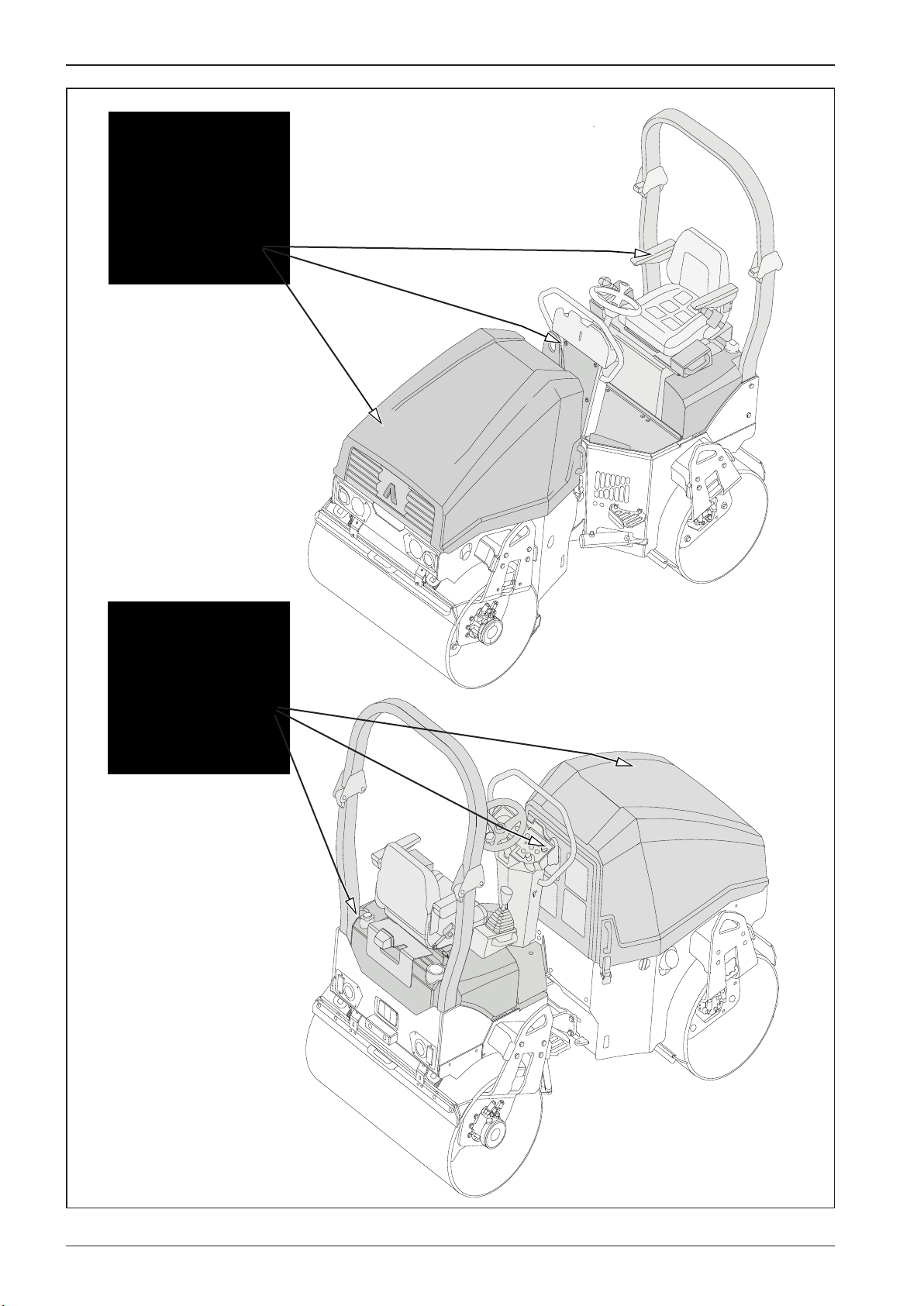
588589A
2.3 Preservation and storage
36 ARX 23-2 T4i, ARX 26-2 T4i
Page 41

OPERATING MANUAL
2.3.3 Machine depreservation
• Check all parts of the machine for damage during storage
and for missing parts.
If the machine has been preserved, remove the preservative agents as follows:
Wash o the preservative agents using a high-pressure
stream of hot water with common degreasers:
- Wash the machine while observing environmental
principles.
- Caution! Do not use a high-pressure stream to wash
the edge cutter and the highlighted parts of the machine as shown in Fig. 588589A, as this could seriously damage the machine.
- Prevent water from entering the air lter, electrical
and electronic parts of the machine.
- Do not use a high-pressure stream near the control
unit!
- Use a high-pressure stream at a maximum angle of 90
degrees downwards.
Remove the preservation and wash the machine in places with intercepting sumps to catch the water and de-
-preservation agents.
Remove the preservation according to the manufacturer's manual.
Before putting the machine into operation, check the operating uids.
37ARX 23-2 T4i, ARX 26-2 T4i
Page 42

38 ARX 23-2 T4i, ARX 26-2 T4i 39ARX 23-2 T4i, ARX 26-2 T4i
Page 43

2.4 Machine disposal after its service life
When disposing the machine following its service life, the user
is obliged to follow national waste and environmental regulations and acts. In the above cases, we recommend you to always
contact:
• specialized companies with arespective authorization for
these operations
• the machine manufacturer or accredited contracting service
organizations authorized by the manufacturer.
The machine manufacturer Ammann shall not be liable
for damage to the health of users or environmental damage caused by non-compliance with the above mentioned rules.
Page 44

588010A
593058
2.5 Machine description
19
13
15
5
15
18
16
8
14
7
9
3
14
6
17
15
2
14
15
11
12
10
7
1
4
6
14
40 ARX 23-2 T4i, ARX 26-2 T4i
Page 45

OPERATING MANUAL
Legend:
1 - Front frame
2 - Rear frame
3 - Front drum
4 - Rear drum
5 - Engine
6 - Travel hydraulic motor
7 - Vibration hydraulic motor
8 - Steering joint
9 - Hydraulic oil level indicator
10 - Fuel tank
11 - Sprinkling tank
12 - Sprinkling lter
13 - Operator’s stand
14 - Drum sprinkling
15 - Drum scraper
16 - Exhaust pipe
17 - Battery
18 - Hydraulic oil cooler
19 - Air lter
41ARX 23-2 T4i, ARX 26-2 T4i
Page 46
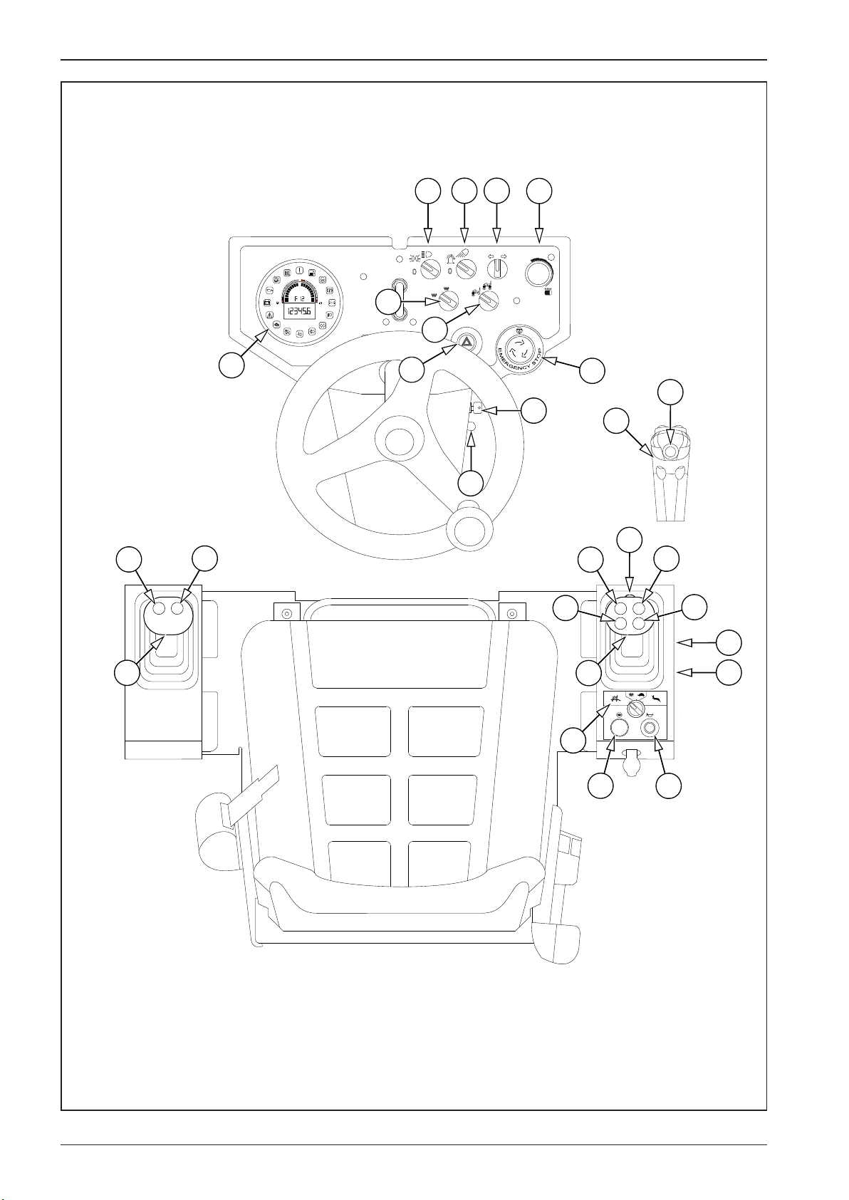
593001B
2.6 Controls and checking instruments
10
1
8
5
13
11
12
20
0
1
15V
3/4
13V
2/4
11V
1/4
9V
h
0
AUT
MAN
7
1
0
9
18
6
14
19
11
3
14
12
15
13
16
B
11
012
A
4
2
42 ARX 23-2 T4i, ARX 26-2 T4i
17
Page 47

OPERATING MANUAL
2.6.1 Dashboard and control panels
Legend:
A - Brake test button
B - Calibration button
1 - Beacon and rear light change-over switch
2 - Dierential lock button
3 - Engine speed selector
4 - Travel mode switch
5 - Sprinkling potentiometer
6 - Emergency brake button
7 - Vibration mode selector switch (manual mode / automatic mode)
8 - Turn indicators switch
9 - Vibrating drum selector switch
10 - Lights switch (outline lights / front lights)
11 - Travel control
12 - Vibration switch
13 - Sprinkling switch
14 - Edge cutter sprinkling switch
15 - Edge cutter button – up
16 - Edge cutter button – down
17 - Horn switch
18 - Warning lights
19 - Ignition box
20 - Display
43ARX 23-2 T4i, ARX 26-2 T4i
Page 48
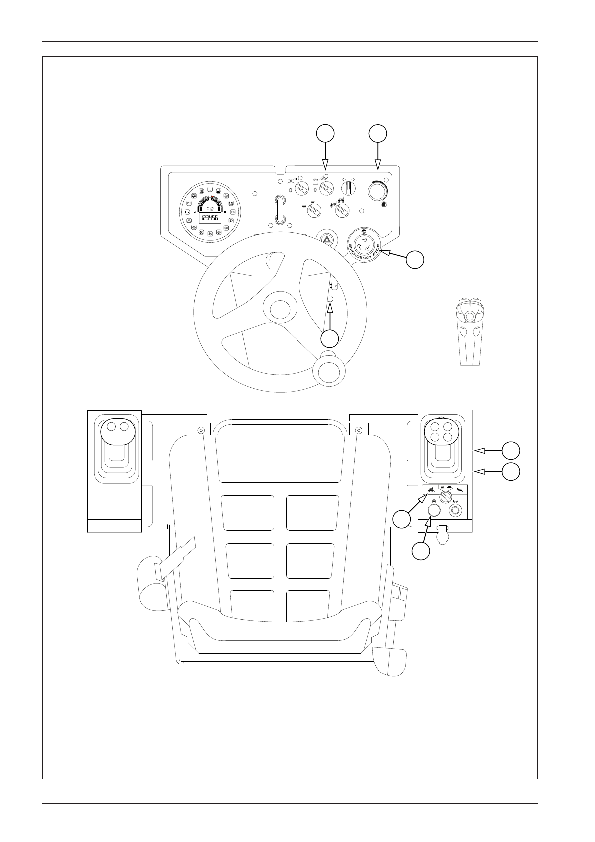
593002B
2.6 Controls and checking instruments
1
0
1
15V
3/4
13V
2/4
11V
1/4
9V
h
0
AUT
MAN
5
1
0
6
3
B
A
012
4
2
44 ARX 23-2 T4i, ARX 26-2 T4i
Page 49
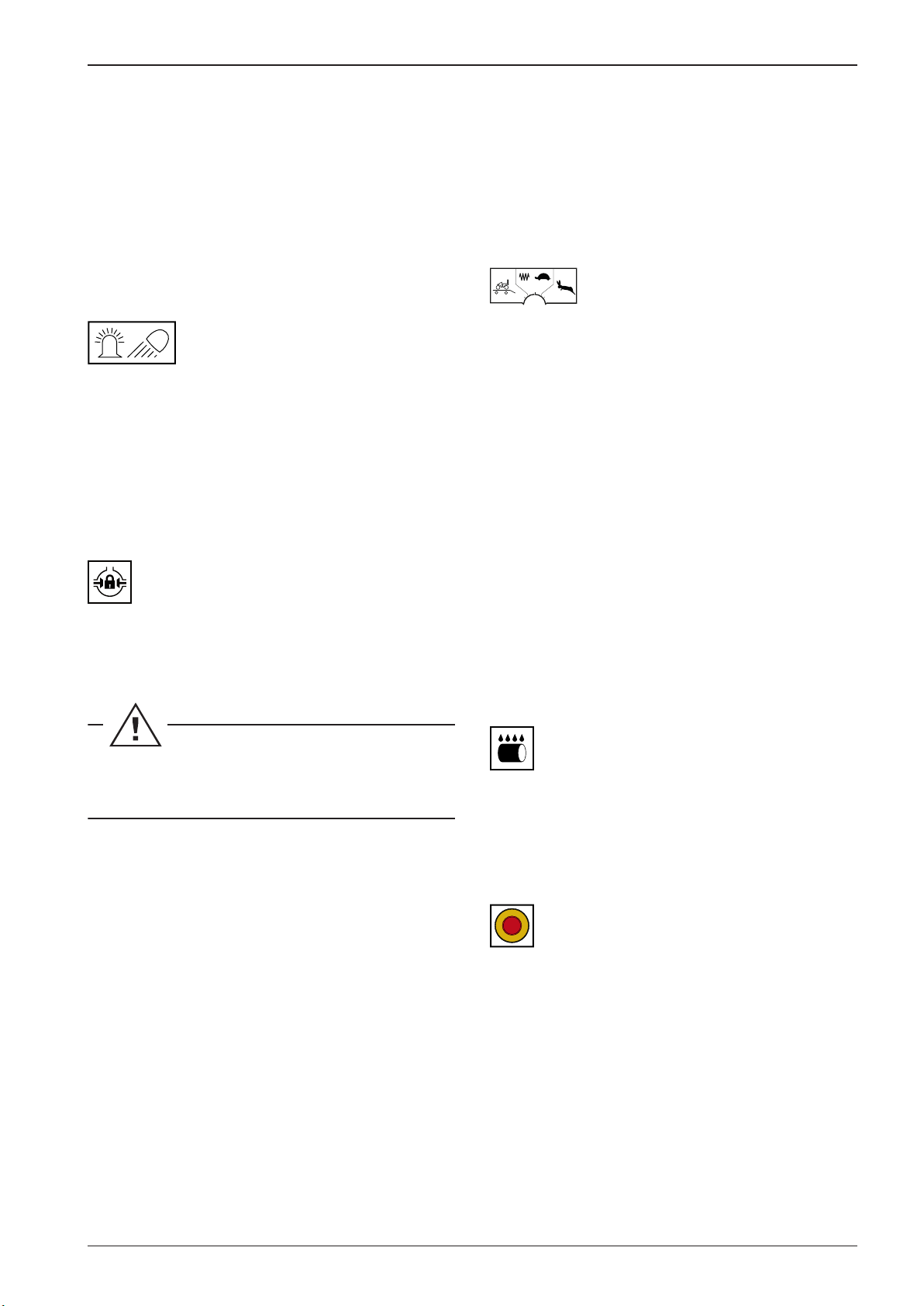
OPERATING MANUAL
AMN138
AMN45
AMN010D
AMN83
AMN142
Brake test button (A)
Used to check the correct brake function.
Calibration button (B)
Used to calibrate functions:
• start ramp HARD / SOFT
• activation of the left travel lever
• infra thermometer setting °C / °F
Beacon and rear light change-over switch
(1)
• To the gear 1: The beacon is ON.
It is possible that the machine is equipped with abeacon but
the corresponding change-over switch is missing. In such
acase, the beacon will start in continuous operation as soon as
the ignition key is set to the position II.
Big working speed:
Frequency II
100% vibration capacity
100% travel speed (depending on the transport and working
speed change-over switch)
100% engine speed
1
2
0
Travel mode switch (4)
Loading mode (0)
• Limited travel speed.
• Activated dierential lock.
• Blocked working functions of the machine (vibration).
Working mode (1)
• Machine working speed (7 km/h).
• Option to activate the dierential lock for the time necessary.
• Option to activate the working functions of the machine
(vibration).
Dierential lock button (2)
It is used for turning on the dierential lock.
The dierential lock prevents the drum from slipping when
crossing adicult terrain.
Turn the dierential lock o after the dicult ground
has been overcome!
Engine speed control (3)
The control setting allows you to better adjust the speed and
the vibration power to the given soil conditions.
Idle speed: Set the control to the rst position.
Small working speed: Set the control to the position I (85%).
Big working speed: Set the control to the position II (100%).
Transport mode (2)
• Machine transport speed (10 km/h).
• Deactivated dierential lock.
• Blocked working functions of the machine (vibration).
Sprinkling potentiometer (5)
OFF in the position “0”. Turn the sprinkling potentiometer from
the position “1” to the position “MIN” to smoothly control the
sprinkling intensity of the drums.
STOP
STOP
STOP
Emergency brake button (6)
Pressing the button activates the emergency brake of the machine. The machine stops, the engine shuts down. After activating the emergency brake button the indicator lamps for battery
charging (22), engine lubrication (23), parking brake (29) and
emergency stop (26) are shown on the display.
Small working speed:
Frequency I
85% vibration capacity
85% travel speed (depending on the transport and working
speed change-over switch)
85% engine speed
45ARX 23-2 T4i, ARX 26-2 T4i
Page 50
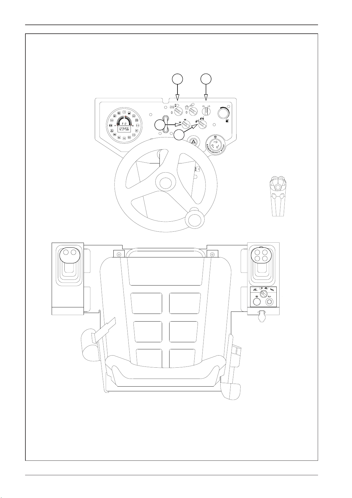
593003C
2.6 Controls and checking instruments
10
0
1
15V
3/4
13V
2/4
11V
1/4
9V
h
0
AUT
MAN
7
8
1
0
9
012
46 ARX 23-2 T4i, ARX 26-2 T4i
Page 51

OPERATING MANUAL
3726G
3726CH
AMN441
AMN139
Vibration mode selector switch (manual
AUTMAN
mode / automatic mode) (7)
• Manual vibration mode – vibration can be switched on
when the machine is stationary or moving. Drum sprinkling
– vibration can be switched on when the machine is stationary or moving.
• Automatic vibration mode – vibration is automatically swit-
ched on when the machine starts moving and automatically
switched o when the machine stops. Automatic activation
of drum sprinkling when the machine starts moving and automatic deactivation of drum sprinkling when the machine
stops.
Direction lights switch (8)
Vibrating drum selector switch (9)
• front drum
• front and rear drum
Lights switch (parking lights / headlamps)
(10)
• parking lights
• headlamps
47ARX 23-2 T4i, ARX 26-2 T4i
Page 52
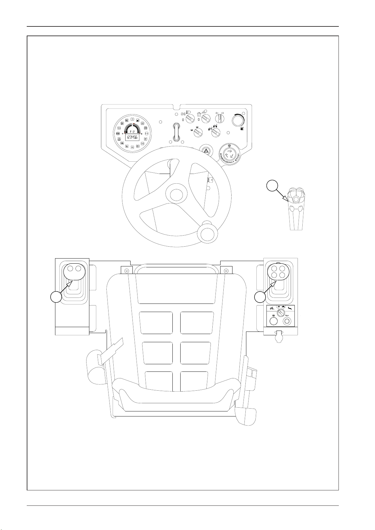
593A003C
2.6 Controls and checking instruments
11
0
1
15V
3/4
13V
2/4
11V
1/4
9V
h
0
AUT
MAN
1
0
11
11
012
48 ARX 23-2 T4i, ARX 26-2 T4i
Page 53

OPERATING MANUAL
Travel control – right (standard) (11)
The travel control is used to set the engine speed, the parking
brake, forward/reverse direction and the travel speed of the machine. Direction and speed of machine travel is controlled by
shifting the control from zero position (0) forward or backward.
The travel speed corresponds to the displacement of the travel
control at the set speed gear. The travel control is xed in the set
position except for the zero position (0).
The travel control can activate the so-called panic response
(Chapter 2.7.2).
Shifting the control to the neutral position (N) stops the machine – the parking brake is not engaged!
If you leave the travel lever in the neutral position (N),
it is possible that the machine will move from the slope
due to leakages of the hydraulic system.
The parking brake position (P) is indicated by lighting up of the
parking brake indicator lamp.
The travel control is tted with vibration, drum sprinkling, edge
cutter (up/down) and edge cutter sprinkling switches.
P – Parking brake – parking brake of the machine enabled
N – Neutral – the machine is not braked
0 – Zero position
F – Forward travel
R – Reverse travel
Travel control – left (optional)
The travel control is used to set the engine speed, the parking
brake, forward/reverse direction and the travel speed of the machine. Direction and speed of machine travel is controlled by
shifting the control from zero position (0) forward or backward.
The travel speed corresponds to the displacement of the travel
control at the set speed gear. The travel control is xed in the set
position except for the zero position (0).
The travel control can activate the so-called panic response
(Chapter 2.7.2).
Shifting the control to the neutral position (N) stops the machine – the parking brake is not engaged!
If you leave the travel lever in the neutral position (N),
it is possible that the machine will move from the slope
due to leakages of the hydraulic system.
The parking brake position (P) is indicated by lighting up of the
parking brake indicator lamp.
The travel control is tted with vibration and drum sprinkling.
P – Parking brake – parking brake of the machine enabled
N – Neutral – the machine is not braked
0 – Zero position
F – Forward travel
R – Reverse travel
Note
If requested by the customer, the machine can be equipped
with the second travel control (11) placed on the left armrest.
However, only one of travel controls (11) may remain active.
For the machine travel using one of the controls (the active one),
the inactive travel control must be set to the parking brake position (P). If the inactive control is deected from the parking
brake position (P), the machine will stop. When the machine is
stopped, move both of the travel controls (11) to the parking
brake position (P) and then select the driving direction on the
active travel control (11).
49ARX 23-2 T4i, ARX 26-2 T4i
Page 54
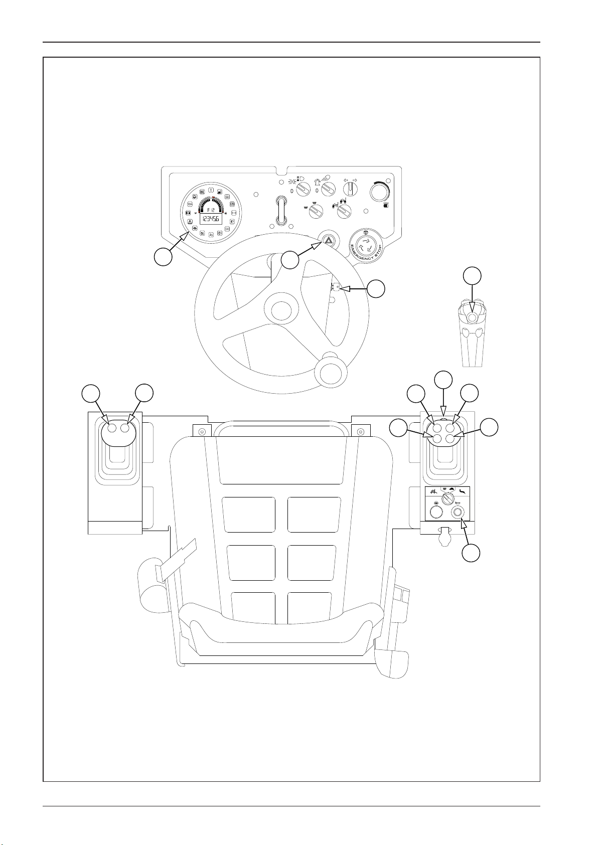
593004C
2.6 Controls and checking instruments
13
12
20
0
1
15V
3/4
13V
2/4
11V
1/4
9V
h
0
AUT
MAN
1
0
18
14
19
14
12
15
13
16
012
17
50 ARX 23-2 T4i, ARX 26-2 T4i
Page 55

OPERATING MANUAL
2612
AMN83
AMN83
3355
3355
2246
595417
Vibration switch (12)
Press the switch to turn on/o the vibration function.
Sprinkling switch (13)
Press the switch to turn on/o the drum sprinkling function.
Edge cutter sprinkling switch (14)
Press the switch to turn on/o the edge cutter sprinkling function.
Ignition box (19)
0 - OFF
I - ON
II - Engine glowing
III - Engine starting
Display (20)
Instrument to display parameters and functions of the engine
and of the machine.
Edge cutter button – up (15)
Pressing the button sets the edge cutter to the transport position.
Edge cutter button – down (16)
Pressing the button sets the edge cutter to the transport position.
Warning horn button (15)
Warning lights switch (16)
51ARX 23-2 T4i, ARX 26-2 T4i
Page 56

588015A
2.6 Controls and checking instruments
25
26
27
24
1
15V
23
3/4
2/4
1/4
13V
22
h
40
21
36
35
39
Display (20)
Instrument to display parameters and functions of the engine and of the machine.
34
28
29
11V
9V
37
30
31
32
33
38
Indicator lamps
21 - Error message indicator lamp
22 - Battery charging indicator lamp
23 - Engine oil pressure indicator lamp
24 - Coolant temperature indicator lamp
25 - Hydraulic oil temperature indicator lamp
26 - Emergency stop indicator lamp
27 - Fuel reserve indicator lamp
28 - Engine glowing indicator lamp
29 - Brake indicator lamp
30 - Outline lights indicator lamp
The warning indicator lamps for engine oil pressure, battery charging and brakes must light up when the ignition is ON. As soon as you
start the engine, the indicator lamps must go o.
31 - Low beam lights indicator lamp
32 - Indicator lamp for direction indicators
33 - DPF clogging indicator lamp
34 - Indicator lamp of high temperature of exhaust gases
35 - Suppression of DPF regeneration indicator lamp
36 - Engine failure indicator lamp
37 - Battery voltage indicator
38 - Engine hour counter
39 - Error message indicator
40 - Fuel tank indicator
52 ARX 23-2 T4i, ARX 26-2 T4i
Page 57
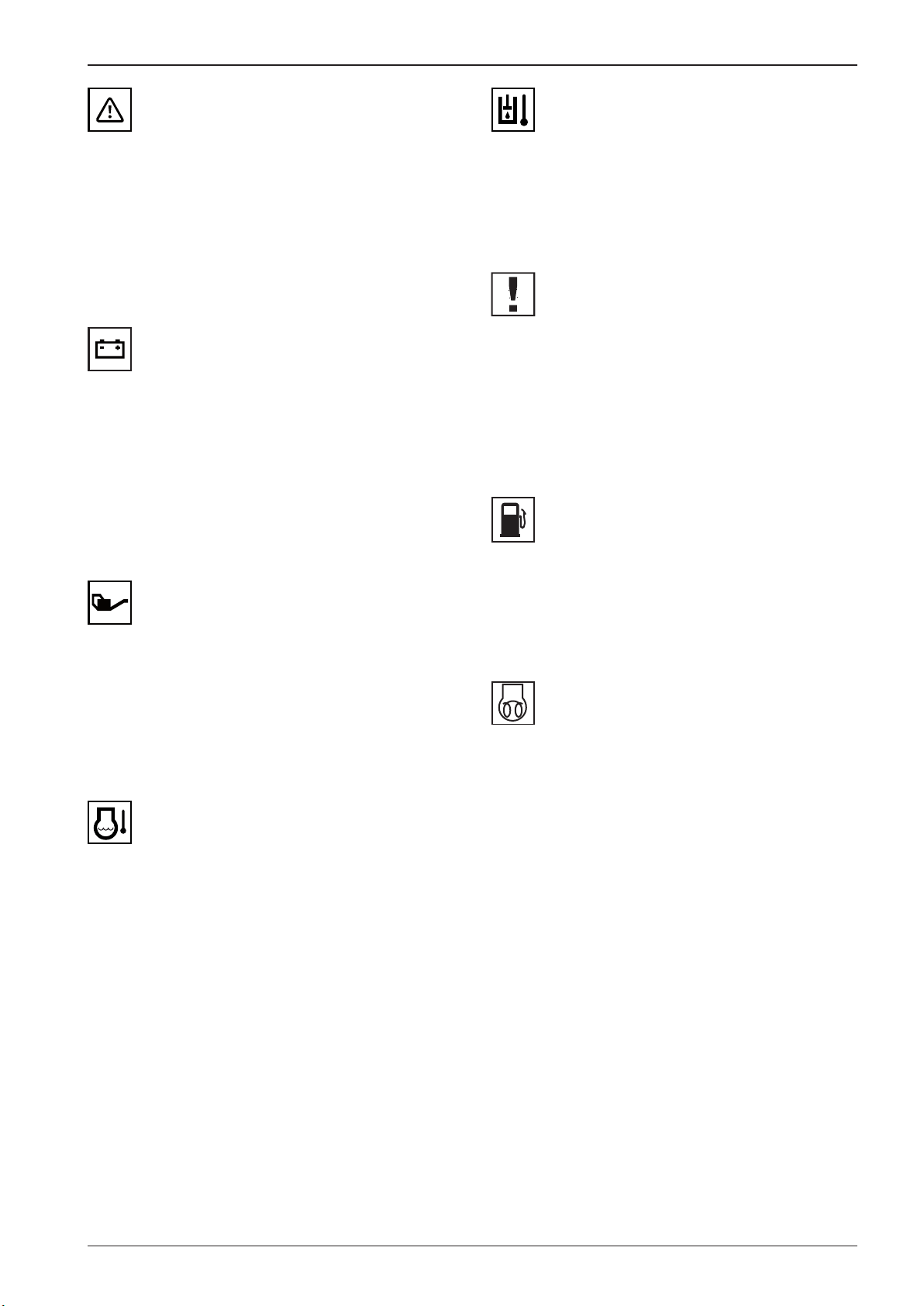
OPERATING MANUAL
2635
592520
3518
AMN58
2777
AMN49
AMN76
Error message indicator lamp (21)
The error message indicator lamp lights up when the control
system detects an error. At the same time, the error code appears on the display.
• Check the machine according to the table of error message
codes.
If the indicator lamp remains lighting, call the service!
Battery charging indicator lamp (22)
When the battery charging indicator lamp lights up during operation or it does not go o after the engine is started, carry out
the undermentioned steps:
• Stop the engine.
• Check the V-belt of the engine for damage and loosening. If
the indicator lamp is still lit up when the engine is started,
contact the service centre.
Hydraulic oil temperature indicator lamp (25)
The hydraulic oil temperature indicator lamp lights up when the
oil temperature exceeds 85°C.
If the oil temperature exceeds 95°C, the error F32 will appear.
Emergency stop indicator lamp (26)
The emergency stop indicator lamp lights if the emergency
brake button (6) is enabled.
If the indicator lamp does not go o when the emergency brake
button is disabled, look for the cause!
The engine can be started only after the defect is repaired!
Fuel indicator lamp (27)
Engine lubrication indicator lamp (23)
When the engine lubrication indicator lamp lights up during
operation or does not go o after the engine is started up, you
must stop the machine immediately and turn o the engine!
• Check the engine for oil leaks and for correct oil level.
• If the oil level in the engine is correct, call the service!
Engine overheating indicator lamp (24)
When the engine overheating indicator lamp lights up during
operation, turn o the engine and rell the coolant! Check the
cooling circuit for leaks! Check the hoses for damage and missing hose clips.
When the fuel indicator lamp lights up, the tank capacity is sufcient for half-hour operation of the machine.
Rell the fuel!
Engine glowing indicator lamp (28)
It indicates the engine warming up before the cold start.
53ARX 23-2 T4i, ARX 26-2 T4i
Page 58

2.6 Controls and checking instruments
2703
AMN146
596303
595200
AMN118
AMN120
Parking brake indicator lamp (29)
The lighting indicator lamp indicates that the parking brake was
enabled.
Outline lights indicator lamp (30)
The indicator lamp indicates that the parking lights are ON.
Headlamps indicator light (31)
The indicator lamp indicates that the headlamps are ON.
Indicator lamp of DPF (Diesel Particulate Filter)
clogging (33)
The machine is not equipped with aDPF.
Indicator lamp of high temperature of exhaust
gases (34)
The function is not activated.
Indicator lamp for direction indicators (32)
The indicator lamp indicates that the directions indicators are
ON.
54 ARX 23-2 T4i, ARX 26-2 T4i
Page 59

OPERATING MANUAL
AMN442
AMN47
2777
Indicator lamp of DPF (diesel particulate lter)
regeneration suppression (35)
The machine is not equipped with aDPF.
Engine failure indicator lamp (36)
The indicator lamp indicates an engine failure.
The lighting indicator lamp during operation of the engine indicates afailure.
The engine stalls – the machine stops and the parking brake is
engaged.
The engine can be started only after the defect is
repaired!
Worked hours indicator (38)
Error message code indicator (39)
Fuel level indicator (40)
Battery voltage indicator (37)
55ARX 23-2 T4i, ARX 26-2 T4i
Page 60
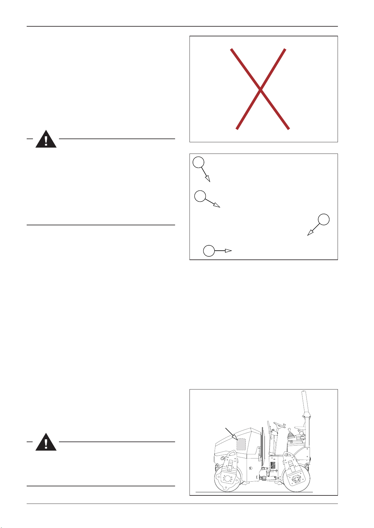
615025
588070C
S588001
2.6 Controls and checking instruments
Seat
Seat adjustment
1 Backrest inclination adjustment
2 Seat springing stiness
3 Longitudinal seat travel
4 Seat cross travel
Seat springing stiness
Turn the switch (2) to set stiness according to driver’s weight
between 50 and 120 kg (110 - 265 lb).
Adjust the seat before driving the machine.
The driver must be fastened with the safety belt while
driving.
Non-observance of this instruction can lead to death or
serious injury.
During travel of the machine, the driver must have his
legs on the machine platform; there is a risk of injury
when the machine turns.
Longitudinal seat travel
• After raising the lever (3), it is possible to move the seat in
the longitudinal direction forward-rearward.
Seat cross travel
• After raising the lever (4), it is possible to move the seat in
the cross direction to the left and right.
2
1
3
4
Document box
The storage box situated on the inner left side of the bonnet is
used to store the Operating Manual and other documents related to the operation of the machine.
The Operating Manual must always be kept in the machine in an appropriate place to be always available for
the driver of the machine for viewing.
56 ARX 23-2 T4i, ARX 26-2 T4i
Page 61

OPERATING MANUAL
Seat switch
The seat switch is located in the seat cushion.
If the driver is not sitting on the seat, the seat switch is deactivated and the operation of the machine is restricted in one of the
following ways – blocking of engine start, blocking of moving
o, stopping of the machine or switching o the engine.
These restrictions vary depending on:
• the time period for which the seat switch is deactivated,
• the position of the travel control (if it is in the parking brake
“P” position or outside this position)
Engine start blocking
If the driver is not sitting on the seat, engine start is blocked unless the travel control is in the parking brake position (P).
To enable engine start, set the travel control to the parking
brake position (P).
Movement blocking
If the driver is not sitting on the seat, moving o is blocked. In
this case, moving the travel control out of the parking brake (P)
position immediately switches o the engine with a 5 second
delay.
To enable engine start, sit on the seat and set the travel control
to the parking brake position (P).
Machine stop
If the driver leaves the seat for more than 5 seconds and less
than 10 seconds when the travel control is not in the parking
brake position (P), the machine stops. The traction force of the
machine is o, vibration is o and, after a delay, the parking
brake engages (P).
To be able to move o again, sit on the seat and set the travel
control to the parking brake position (P).
Engine shutdown
If the driver leaves the seat for more than 10 seconds when the
travel control is not in the parking brake position (P), the engine
shuts down.
To re-enable engine start, sit on the seat and set the travel control to the parking brake position (P).
It is forbidden to load the seat switch with other items!
When operating the machine, the driver must follow the
safety regulations and not carry out any activity that might endanger the safety of work; the driver must fully
focus on steering the machine.
When operating the machine, the driver must always sit
on the seat.
When leaving the machine, the driver must take measures against unauthorized use of the machine and against
unintentional starting.
57ARX 23-2 T4i, ARX 26-2 T4i
Page 62
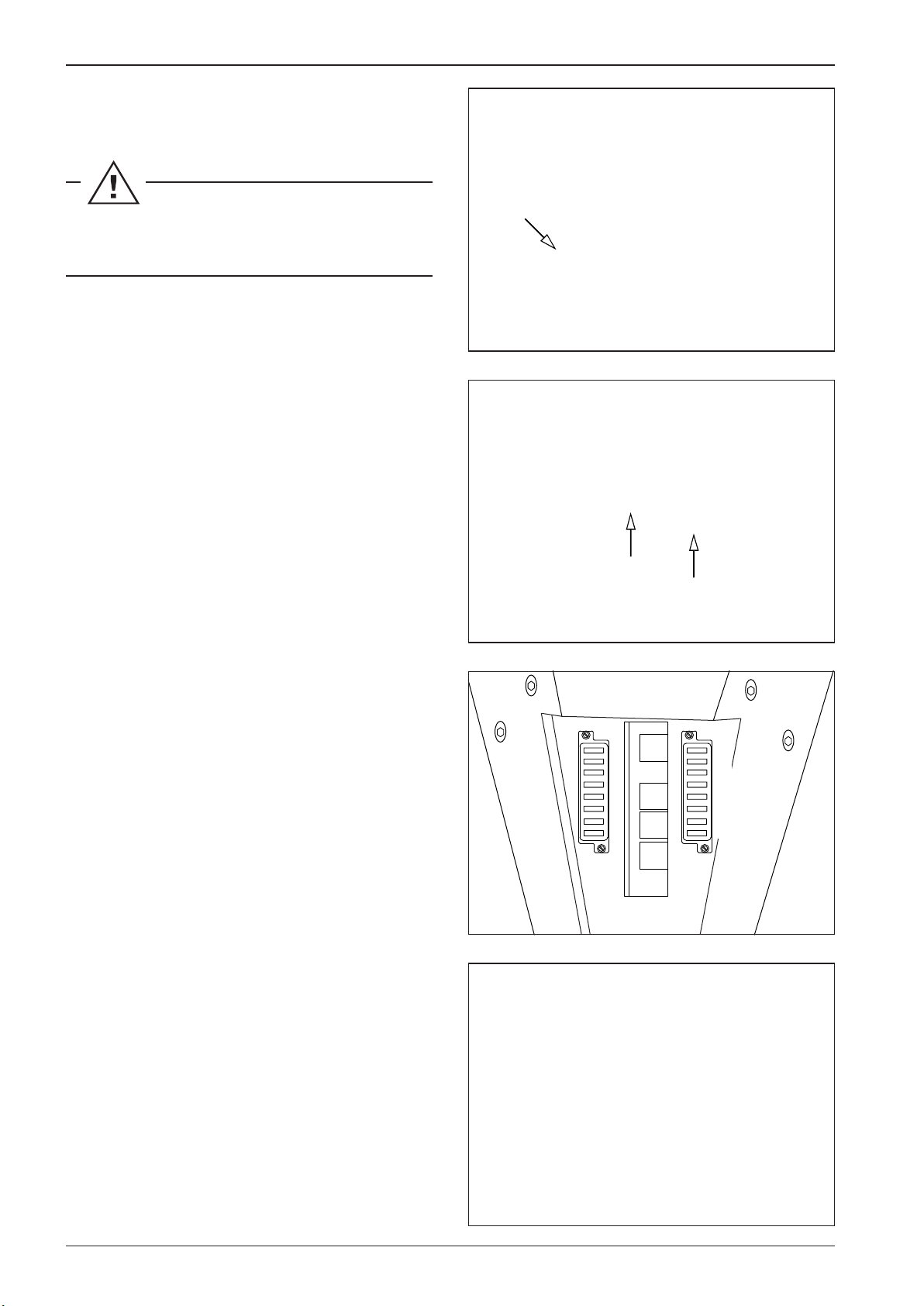
593300
588072
611321
593016
2.6 Controls and checking instruments
Fire extinguisher (optional equipment)
Place to install are extinguisher.
The manufacturer recommends that the machine be
equipped with are extinguisher.
Fuse box
F1 – 7.5 A .......... Parking lights
F2 – 7.5 A
F3 – 15 A
F4 – 15 A
F5 – 5 A
F6 – 5 A
F7 – 40 A
F8 – 5 A
F9 – 25 A
F10 – 10 A
F11 – 7.5 A (15 A*) Water sprinkling pump, emulsion sprinkling
F12 – 7.5 A
F13 – 7.5 A
F14 – 5 A
F15 – 5 A
F16
.......... Tail lights, licence plate light
........... Headlamps
........... Rear light, ROPS lights, beacon, green beacon,
monitoring device
.............. Direction indicators
.............. Control unit – electronics
........... Control unit – power part
.............. Display, alternator excitation
........... Hydraulic oil cooler
......... Service socket, seat heating
pump at the axle
........ Right travel lever, left travel lever, dierential
lock switch, working mode selector, horn
switch, brake tester, calibration button
........ Horn
........... Seat switch
........... Infra thermometer, monitoring device
...................... Reserve
F1
F2
F3
F4
F5
F6
F7
F8
F9
F10
F11
F12
F13
F14
F15
F16
* ARX 23-2C, ARX 26-2C
Battery disconnector fuses
F20 – 70 A
F21 – 35 A
F22 – 7.5 A
F23 – 5 A
F30 – 50 A
......... main fuse
......... Intake/holding coil – Intake coil
........ Fuel pump
........... Compaction module
......... Glowing
58 ARX 23-2 T4i, ARX 26-2 T4i
Page 63

588802
588801
611013
611014
OPERATING MANUAL
Dashboard cover
The cover protects the dashboard from:
• weather eects
• vandalism
• handling by others
The cover of the dashboard can be locked with apadlock; the
padlock is not delivered in the machine equipment.
Engine bonnet
The bonnet protects the engine from:
• weather eects
• vandalism
• handling by others
The bonnet of the engine can be locked with apadlock; the padlock is not delivered in the machine equipment.
59ARX 23-2 T4i, ARX 26-2 T4i
Page 64
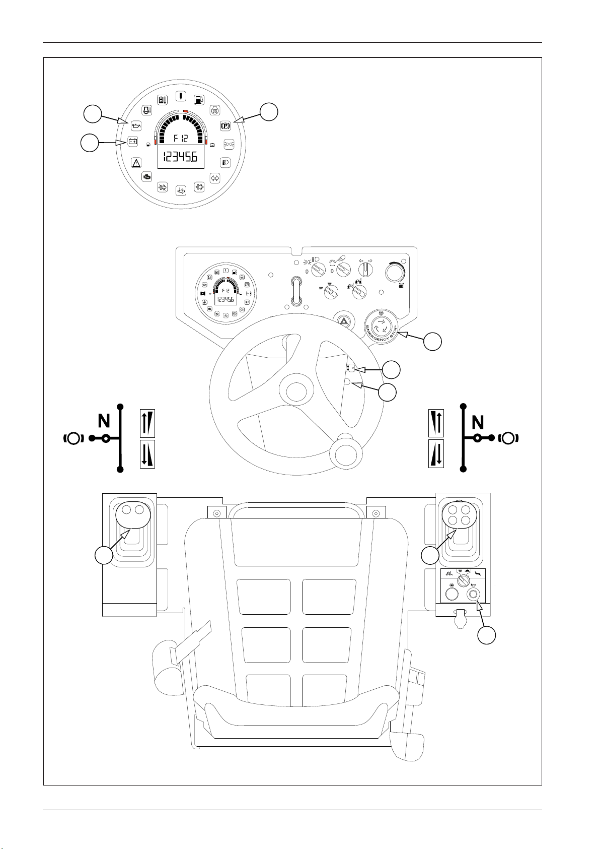
593006B
2.7 Machine operation and use
1
15V
23
22
3/4
2/4
1/4
13V
11V
9V
h
29
0
1
15V
3/4
13V
2/4
11V
1/4
9V
h
0
AUT
MAN
1
0
6
19
3
11
F
0
R
P
012
F
P
0
R
11
17
60 ARX 23-2 T4i, ARX 26-2 T4i
Page 65

595201
OPERATING MANUAL
2.7.1 Starting the engine
Daily before starting the engine, check the oil level in the engine
and in the hydraulic tank, fuel level in the fuel tank and water
level in the water tank. Check that there are no loosened, worn
or missing parts on the machine.
Start the engine only from the driver’s stand! Use the warning
horn to signal the engine starting and check that nobody is endangered by starting the engine!
Starting the engine:
Turn on the battery disconnector.
Sit down on the seat.
Set the engine speed switch (3) to the idling speed position.
Set the travel control (11) to the brake position (P). When the
machine is equipped with two travel controls, set both travel
controls to the parking brake position (P).
Check that the emergency brake (6) is not enabled.
Insert the key into the ignition box (19) in the position “0” and
switch over to the position “I”.
The indicator lamps for battery charging (22), engine lubrication
(23) and parking brake (29) will light up on the display (20).
Use the warning horn (17) to signal that the engine is starting.
Hold the key in the “II” position – engine glowing. The indicator
lamp (29) for engine glowing will light up on the display.
Then turn the key to the “III” position to start the engine. Once
the engine started, release the key. Attention! If the outdoor
temperature drops below 0 °C, keep the key in the “II” position
for 15 s!
After the start, the indicator lamps for battery charging (22), engine lubrication (23) and engine glowing (28) must go out on
the display (20).
19
0
I
II
III
When driving with a cold engine and cold hydraulic oil,
the braking distances are longer than when the oil has
reached its operating temperature.
Do not start the engine for more than 30 seconds. Wait
for 2 minutes before starting again.
Following the engine start let the engine idle at increased speed for 3–5min.
If the coolant temperature does not reach at least 40°C
(104°F), do not load the engine at full power!
Note
If the engine cannot be started or stops after a while, bleed the
fuel system according to Chapter 3.6.49.
61ARX 23-2 T4i, ARX 26-2 T4i
Page 66
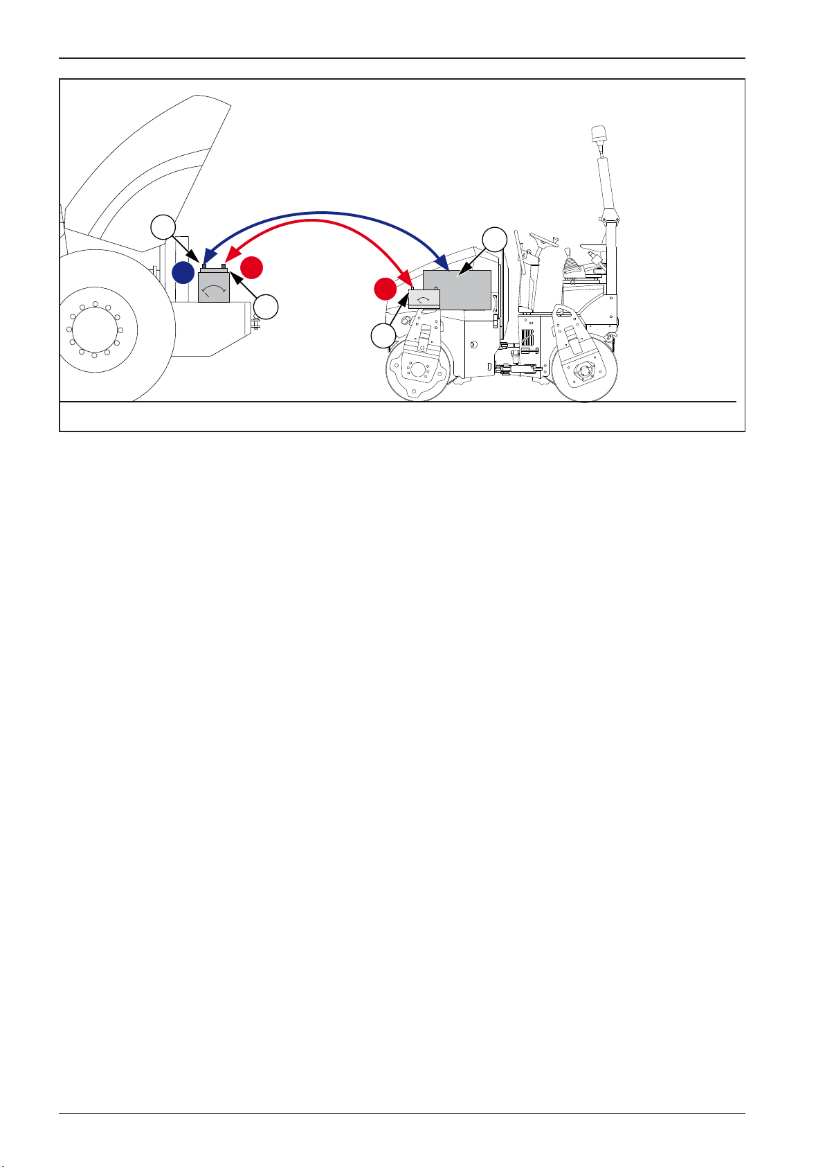
593007
2.7 Machine operation and use
3
4
-
12V
+
0
+
-
12V
0
2
1
62 ARX 23-2 T4i, ARX 26-2 T4i
Page 67

OPERATING MANUAL
Start-up procedure using leads from an external power supply:
The starting supply from the external power supply must be 12V.
Always follow the undermentioned operation sequence.
1/ Connect one end of the (+) pole of the cable to the (+) pole of the discharged battery.
2/ Connect the other end of the (+) pole of the cable to the (+) pole.
3/ Connect one end of the (–) pole of the cable to the (–) pole of the external battery.
4/ Connect the other end of the (–) pole of the cable to any part of the started machine, which is attached to the engine (or with the
engine block itself).
When the engine has been started, disconnect cables in reverse order.
Do not connect the (–) pole of the cable to the (–) pole of the discharged battery of the machine being started! During
the starting heavy sparking may occur and gases of the charged battery may explode.
Uninsulated parts of clamps of the jump leads must not touch each other!
The jump lead connected to the (+) pole of the batteries must not come into contact with electrically conductive parts
of the machine – danger of ashort circuit!
Do not lean over the batteries – possibility of electrolyte burns!
Remove ammable sources (open ame, burning cigarettes, etc.)
Do not check the presence of voltage in the wire by sparking against the machine frame!
63ARX 23-2 T4i, ARX 26-2 T4i
Page 68
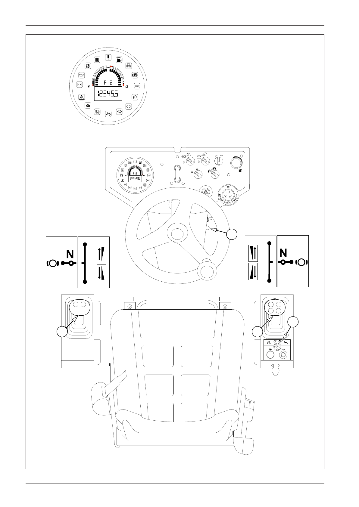
593008B
2.7 Machine operation and use
1
15V
3/4
2/4
1/4
13V
11V
9V
h
0
1
15V
3/4
13V
2/4
11V
1/4
9V
h
0
AUT
MAN
1
0
3
F
P
0
R
F
0
P
R
4
11
11
012
64 ARX 23-2 T4i, ARX 26-2 T4i
Page 69

OPERATING MANUAL
2.7.2 Drive and reverse drive
Before moving o, check that the articulation joint of the machine is locked.
Use the warning horn to signal that the engine is starting and wait long enough so that all persons could leave the area
around the machine or under the machine in time!
Before moving o, check that the area in front of and behind the machine is empty and that there are no persons or
obstructions there!
The operator must not control the machine from the ground. If he did so anyway and is not sitting on the seat when
the travel control is moved from the parking brake position (P), the machine does not disengage the brake and will not
move, and after 5 seconds the engine will be stopped.
The operator must not leave the operator seat when operating the machine. If he does so anyway and leaves the seat
when the travel control is in deected form the parking brake position (P), the machine behaves according to the seat
switch description (Chapter 2.6).
Start the engine
• Start the engine according to Chapter 2.7.1.
• The engine speed control (3) must be in its lower position.
Selection of the working engine speed
• The machine is provided with two working speed positions.
• Small working speed: Set the control to the position I (85%).
• Big working speed: Set the control to the position II (100%).
Small working speed:
• 85% travel speed (depending on the transport and working speed change-over switch)
• 85% engine speed
Big working speed:
• 100% travel speed (depending on the transport and working speed change-over switch)
• 100% engine speed
65ARX 23-2 T4i, ARX 26-2 T4i
Page 70
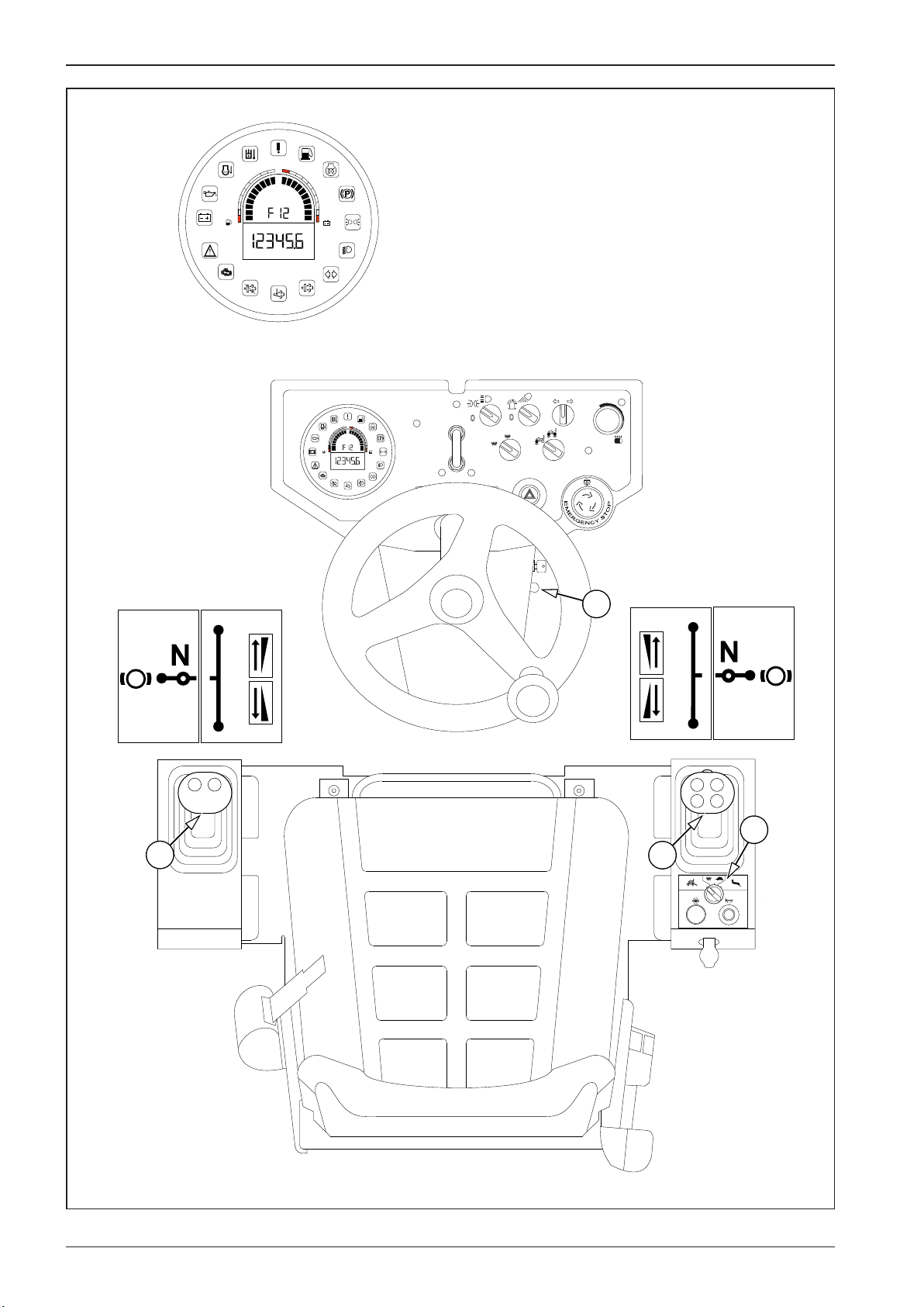
593008B
2.7 Machine operation and use
1
15V
3/4
2/4
1/4
13V
11V
9V
h
0
1
15V
3/4
13V
2/4
11V
1/4
9V
h
0
AUT
MAN
1
0
3
F
P
0
R
F
0
P
R
4
11
11
012
66 ARX 23-2 T4i, ARX 26-2 T4i
Page 71

OPERATING MANUAL
Selection of the travel direction
• Selection of the travel direction is set on the active travel control. Set and leave the inactive travel control in the parking brake
position (P).
• Move the travel control (11) from the parking brake (P) to the neutral position (N) – releasing of the brakes, the parking brake indi-
cator lamp (29) goes out.
• Move the travel control (11) to the position (0) and select a travel direction (F/R).
When the driver releases the travel control (11), it does not return to the zero position automatically. The travel control remains in the
selected position.
When the driver quickly moves the travel control (11) through the zero position (0) from the selected direction of the machine travel,
e.g. due to a dangerous situation, the machine stops and the parking brake is engaged (panic response).
When the driver moves travel control (11) from the selected direction of machine travel to the neutral position, e.g. due
to a dangerous situation, the machine stops but the parking brake is not engaged. This may cause counting movement
of the machine when driving down the slope, due to leakages form the hydraulic system.
Travel speed selection
• The travel speed is set on the active travel control. Set and leave the inactive travel control in the parking brake position (P).
• The travel speed corresponds to the deection of the travel control (11) from the zero position (0) at the given engine speed (3)
and mode of operation (4) of the machine.
• The travel speed can be changed with the travel mode switch (4).
Panic response
The immediate stop of the machine using the travel control (11) applies to all of the travel modes of the machine. When the travel
control (11) is changed to the opposite position through (0) within 1 second, the machine will stop – the parking brake will be engaged
and the engine will keep running, i.e. panic response. When the machine vibration is on, the vibration will stop also when the manual
vibration mode is selected. When the machine is equipped with two travel controls, the panic response can be enabled also on the
inactive travel control. The machine can start moving again after the travel control (11) is changed to the neutral position (0) and the
travel direction (F/R) is selected.
Note
If the driver leaves the driver’s seat while the travel control is not in the brake position (P), the machine behaves according to the seat
switch description (Chapter 2.6).
When the driver moves travel control from the brake position (P) without sitting on the seat at that time, the engine will be stopped
after 5 seconds.
67ARX 23-2 T4i, ARX 26-2 T4i
Page 72
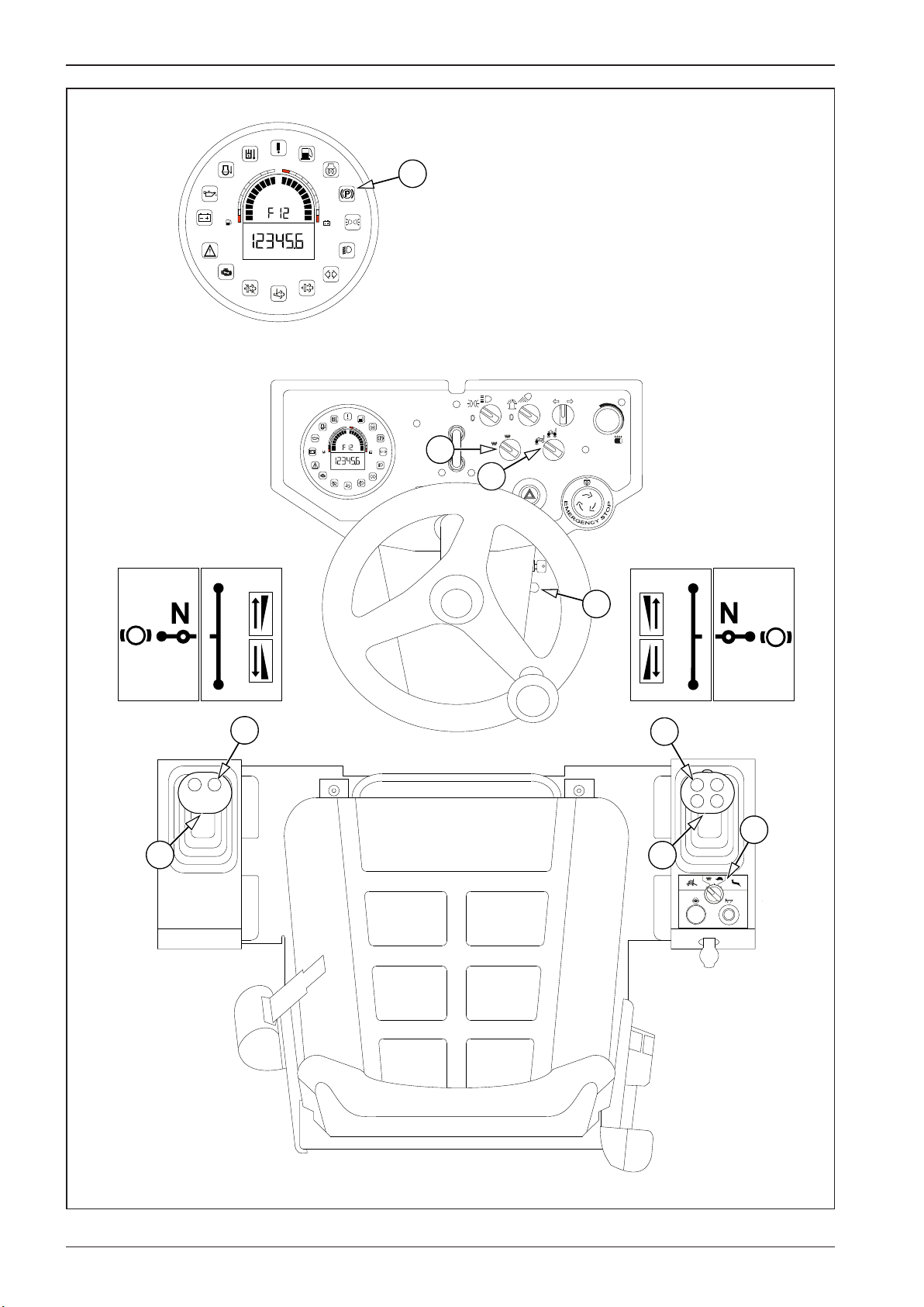
593009B
2.7 Machine operation and use
1
15V
3/4
2/4
1/4
13V
11V
9V
h
29
0
1
15V
3/4
13V
2/4
11V
1/4
9V
h
0
AUT
MAN
7
1
0
9
F
F
3
P
R
0
12
12
0
P
R
4
11
11
012
68 ARX 23-2 T4i, ARX 26-2 T4i
Page 73

OPERATING MANUAL
Machine travel and reversing with vibration
It is forbidden to enable the vibration when the machine is standing.
If the parking brake indicator lamp (29) is on, move the travel control (11) from the parking brake (P) position to the (0) position.
Manual mode
• Use the vibration mode switch (7) to set the manual mode.
• Use the engine speed control (3) to set the working engine speed I or II.
• Use the vibrating drum selector (9) to select the front drum vibration or front and rear drum vibration.
• Use the travel mode switch (4) to set mode “1” – the working mode of the machine.
• Using the travel control (10) select the forward (F) or reverse (R) travel direction.
Turning on
• Turn on the vibration with the switch (12).
Turning o
• Turn o the vibration with the switch (12).
Note
When the travel control (11) is in the zero position (0), vibration of the machine is still active. Vibration is automatically turned o in the
parking brake position (P).
Automatic mode
• Use the vibration mode switch (7) to set the automatic mode.
• Use the engine speed control (3) to set the working engine speed I or II.
• Use the vibrating drum selector (9) to select the front drum vibration or front and rear drum vibration.
• Use the travel mode switch (4) to set mode “1” – the working mode of the machine.
• Using the travel control (11) select the forward (F) or reverse (R) travel direction.
Turning on
• Press the vibration switch (12).
• The vibration will be automatically turned on when the travel speed is more than 1–2km/h (0.6–1.2mph).
• The vibration will be automatically turned o when the travel speed is less than 1–2km/h (0.6–1.2mph).
• Vibration and sprinkling remains enabled even after the travel control (11) has been smoothly shifted through the zero position (0).
Turning o
• Press the vibration switch (12).
Note
When the travel control (11) is kept in the zero position (0) or set to the parking brake position (P), vibration and sprinkling is automatically turned o.
Panic response
The immediate stop of the machine using the travel control (11) applies to all of the travel modes of the machine. When the travel
control (11) is changed to the opposite position through (0) within 1 second, the machine will stop – the parking brake will be engaged
and the engine will keep running, i.e. panic response. When the machine vibration is on, the vibration will stop also when the manual
vibration mode is selected. The machine can start moving again after the travel control (11) is changed to the parking brake position
(P) and the travel direction (F/R) is selected.
69ARX 23-2 T4i, ARX 26-2 T4i
Page 74

2.7 Machine operation and use
70 ARX 23-2 T4i, ARX 26-2 T4i
Page 75
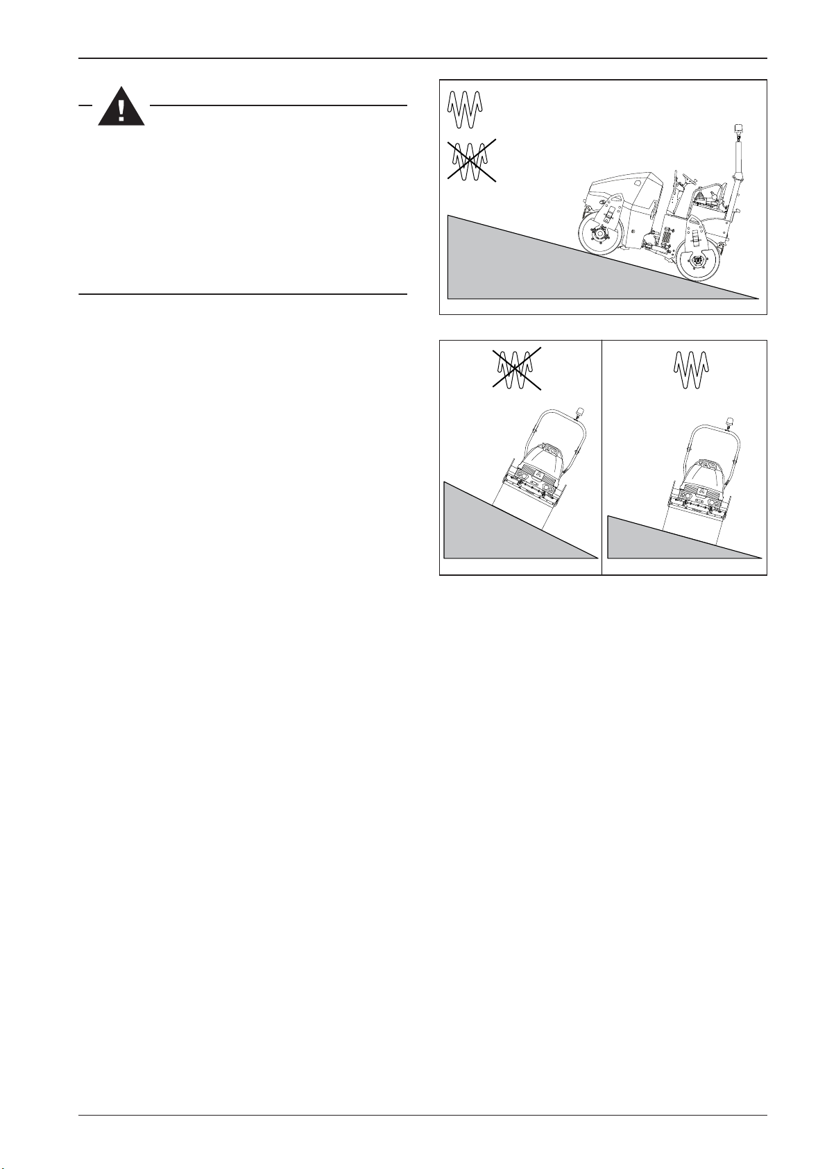
593801
590802
OPERATING MANUAL
MAX 30%
For the maximum permissible slope gradient when driving uphill and across the slope gradient, see gures.
The given values will be lower depending on adhesive
conditions and the instantaneous weight of the machine!
Prevent potential danger and pay extra attention to the
adherence to permitted slope gradients.
Observe safety precautions. The machine operator must
always be fastened with the safety belt.
MAX 35%
MAX
25%
MAX
15%
71ARX 23-2 T4i, ARX 26-2 T4i
Page 76
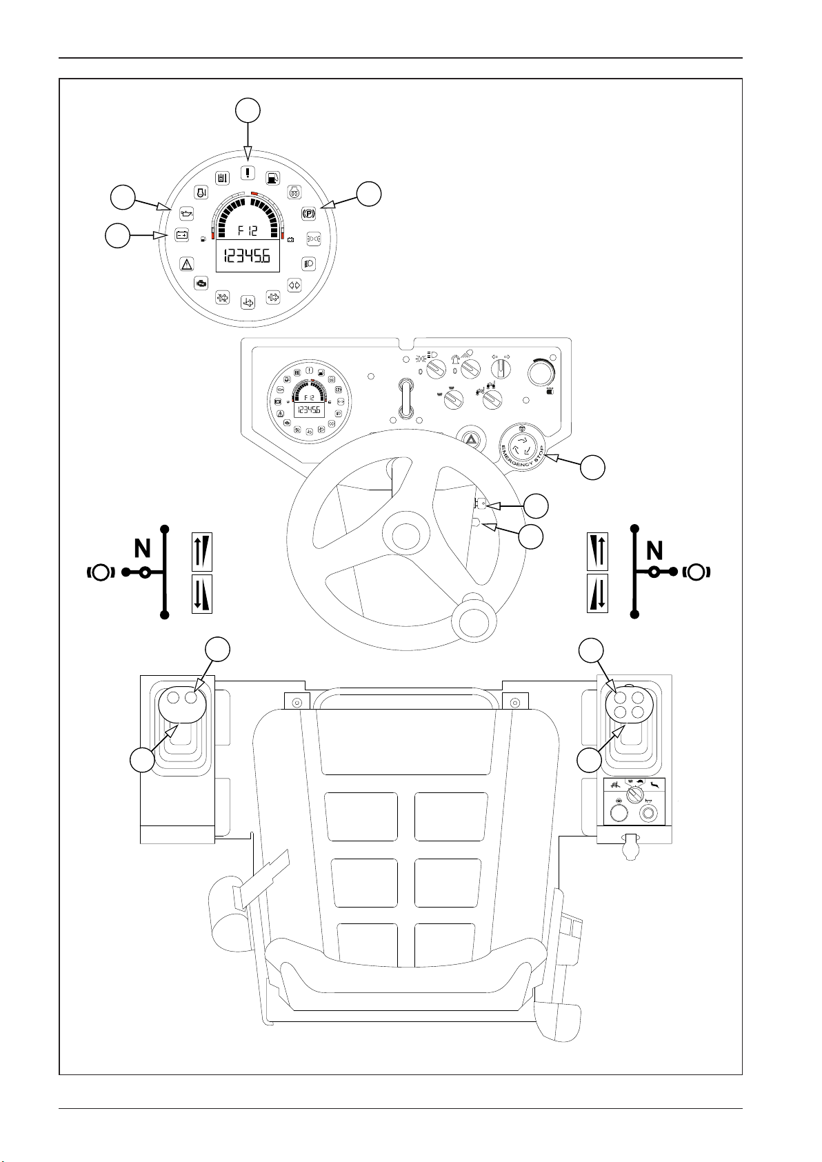
593010B
2.7 Machine operation and use
26
1
15V
23
22
3/4
2/4
1/4
13V
11V
9V
h
29
0
1
15V
3/4
13V
2/4
11V
1/4
9V
h
0
AUT
MAN
1
0
6
19
12
11
F
0
R
P
012
F
P
0
3
R
12
11
72 ARX 23-2 T4i, ARX 26-2 T4i
Page 77

OPERATING MANUAL
2.7.3 Stopping the machine and turning o the engine
Turn o the vibration with the vibration switch (12).
Stop the machine by changing the travel control (11) to the neutral position (N).
Brake the machine by changing the travel control (11) to the brake position (P).
Set the engine speed control (3) to the idle speed.
Switch over the key in the ignition box (19) to the position “0”, take out the key from the ignition box and close the lid.
Turn o the battery disconnector when shutting down the machine.
2.7.4 Machine emergency stop
In a dangerous situation requiring the machine to immediately stop, press the emergency brake button (6).
The machine will stop moving immediately, the engine will stop working and the parking brake will be enabled.
Turning on:
Press the emergency brake button (6) to brake the machine immediately, turn o the engine and apply the parking brake.
The indicator lamps for battery charging (22), engine lubrication (23), parking brake (29) and emergency stop (26) will light up on the
display.
Turning o:
Turn the emergency brake button (6) in the direction of arrows.
The indicator lamps for battery charging (22), engine lubrication (23) and parking brake (29) will remain light up on the display.
Move the travel control (11) to the zero position (0) and the engine speed control (3) to the idle speed position; now start the engine.
73ARX 23-2 T4i, ARX 26-2 T4i
Page 78
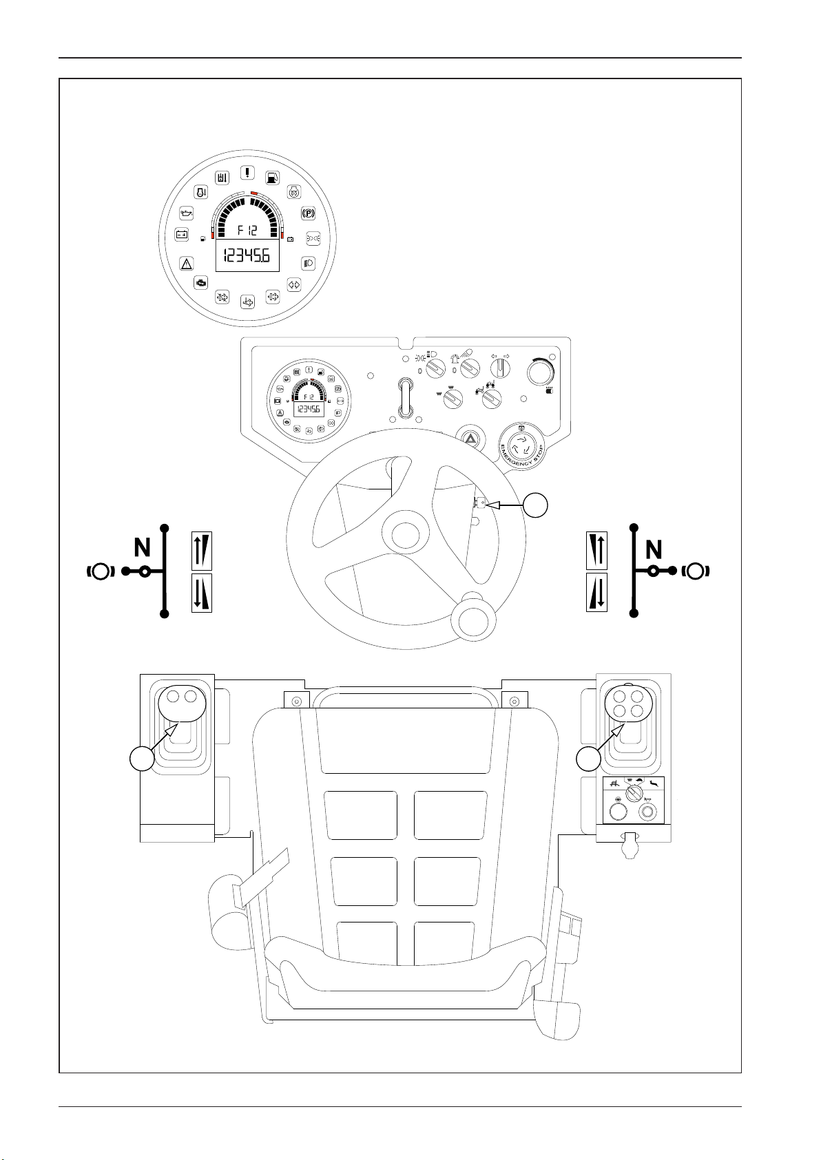
593011B
2.7 Machine operation and use
1
15V
3/4
2/4
1/4
13V
11V
9V
h
0
1
15V
3/4
13V
2/4
11V
1/4
9V
h
0
AUT
MAN
1
0
19
11
F
0
R
P
012
F
P
0
R
11
74 ARX 23-2 T4i, ARX 26-2 T4i
Page 79

OPERATING MANUAL
2.7.5 Machine parking
Shut down the machine on aat and solid surface where there is no potential natural hazard (e.g. landslides, ooding).
Change the travel control (11) to the brake position (P).
Switch over the key in the ignition box (19) to the position “0”, take out the key from the ignition box and close the lid.
Turn o the battery disconnector if it is installed in the machine.
Clean the machine from dirt.
Check the whole machine and repair defects that occurred during operation.
Lock the cover of the dashboard and the engine bonnet with apadlock.
Note
The padlock is not delivered in the machine equipment.
Protect the dashboard and the engine compartment from unauthorized access of others by locking the dashboard cover and the
engine bonnet.
It is forbidden to use the parking brake for bringing the machine to astop.
2.7.6 Panic response
The immediate stop of the machine using the travel control (11) applies to all of the travel modes of the machine. When the travel
control (11) is changed to the opposite position through (0) within 1 second, the machine will stop – the parking brake will be engaged
and the engine will keep running, i.e. panic response. When the machine vibration is on, the vibration will stop also when the manual
vibration mode is selected. The machine can start moving again after the travel control (11) is changed to the parking brake position
(P) and the travel direction (F/R) is selected.
It is forbidden to use the panic response for common stopping the machine. Enable the panic response only in emergency when the machine must be stopped immediately.
75ARX 23-2 T4i, ARX 26-2 T4i
Page 80
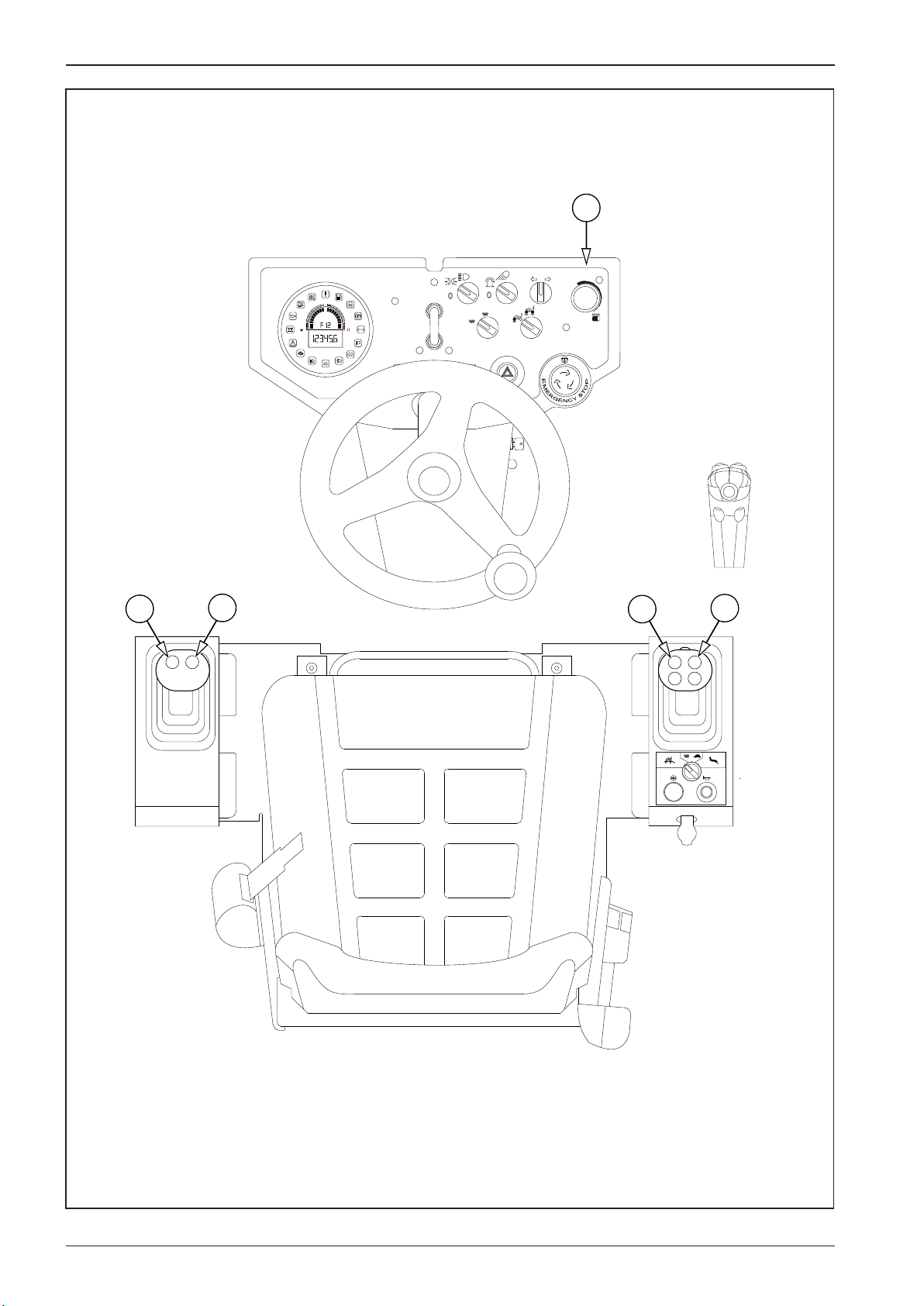
593012B
5
13
12
0
1
15V
3/4
13V
2/4
11V
1/4
9V
h
0
AUT
MAN
1
0
12
13
012
76 ARX 23-2 T4i, ARX 26-2 T4i
Page 81
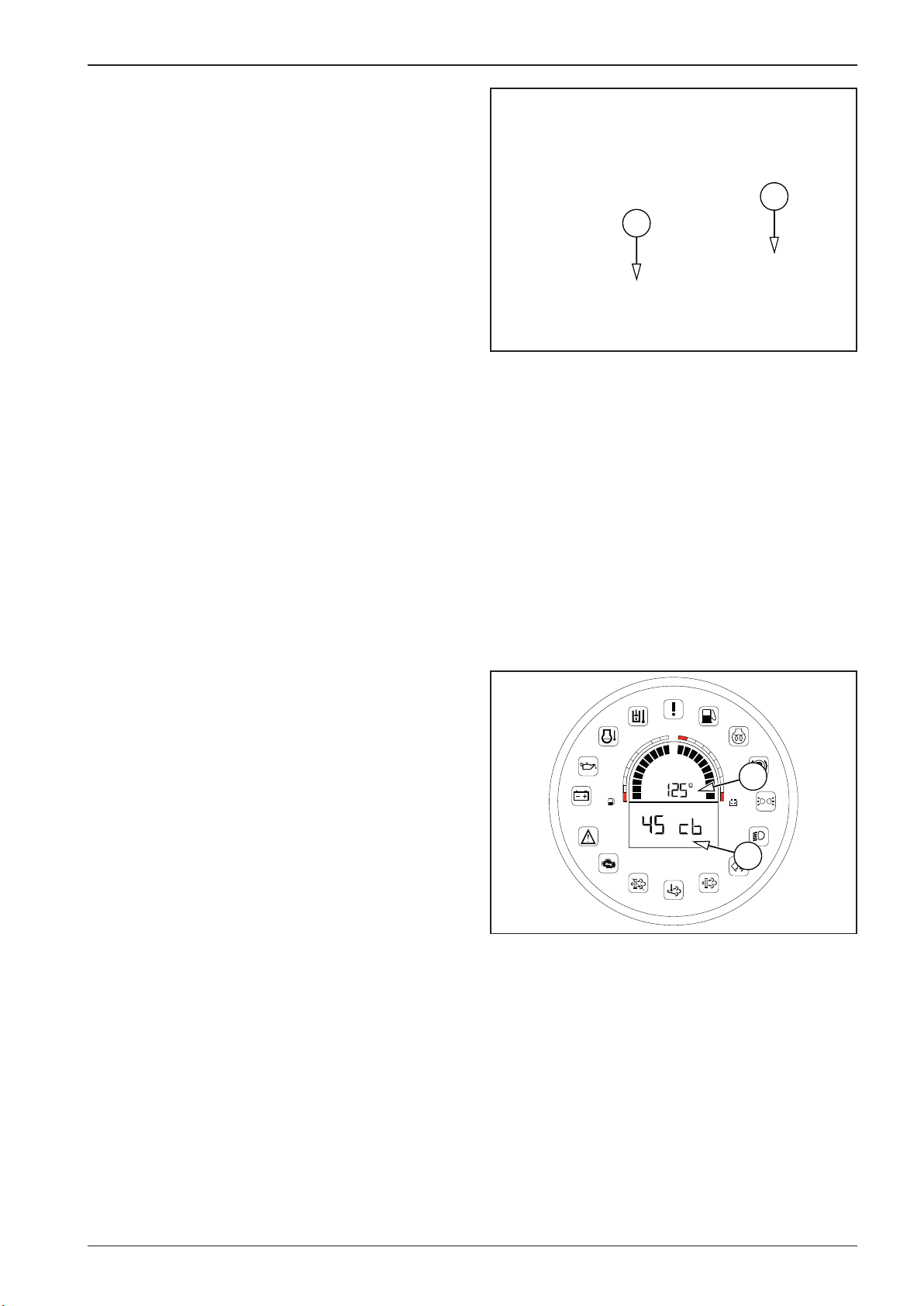
588073
593013
OPERATING MANUAL
2.7.7 Sprinkling
The water level in the tank is shown on the indicator (1).
Hole to ll the water tank (2).
Check the water level in the tank before putting the machine
into operation.
2
Turn on the sprinkling with the sprinkling potentiometer (4).
Position 0 – sprinkling OFF
Position 1 – sprinkling ON
Turning from the position 1 to the right to turn on the interval
sprinkling.
In the interval sprinkling mode you can continuously control
the sprinkling break interval.
Using the sprinkling switch (13), it is possible to turn on the
sprinkling at any time, e.g. before driving on acompacted bitumen surface.
Note
At acombined machine, the sprinkling switch (13) is used for
sprinkling the tyres and the sprinkling potentiometer (5) is used
for sprinkling the drum.
1
2.7.8 ACE Force (optional equipment)
The ACE Force system measures current surface compaction at
the front drum and shows the value of compaction in the unit of
cb (MN/m) on the multifunctional display.
1 - surface temperature
2 - compaction value
ACE Force is switched on and o by pressing the vibration
switch (12). Values are not saved or printed.
1
15V
3/4
2/4
1/4
13V
11V
1
9V
2
77ARX 23-2 T4i, ARX 26-2 T4i
Page 82
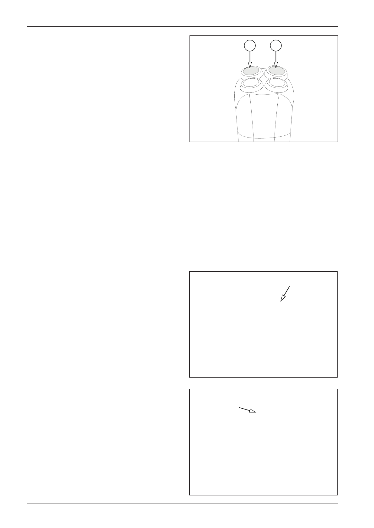
590001F
593071
CAL001
2.7 Machine operation and use
2.7.9 Infrathermometer (optional equipment)
It is activated by turning on the key in the switch box (19) and
it displays the temperature of the bitumen surface being rolled.
The measured temperature in °C is indicated on the display.
Control
In the following text, the “OK button” means the vibration button (12). The “select button” means the sprinkling button (13).
These buttons only work on the right travel control.
Procedure to set the units of measure °C or °F
After setting the required parameters on the display of the infra
thermometer, the values are saved automatically.
12
13
Remove the cover.
Turn the key in the ignition box to the "I" position.
78 ARX 23-2 T4i, ARX 26-2 T4i
Page 83
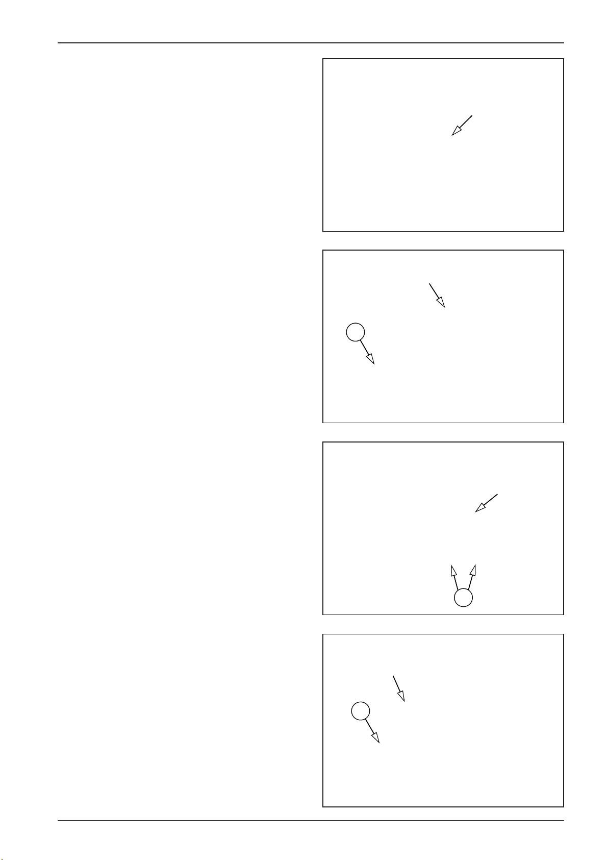
590004F
590003F
590006F
590002F
OPERATING MANUAL
The infra thermometer display will light up.
Switch over with the MODE button (1) until °C appears on the
display.
Switch over with the UP and DOWN arrows (2) until °F appears
on the display.
1
2
Set the current output of the infra thermometer.
• Switch over with the MODE button (1) until the “o” symbol
appears on the display.
1
79ARX 23-2 T4i, ARX 26-2 T4i
Page 84
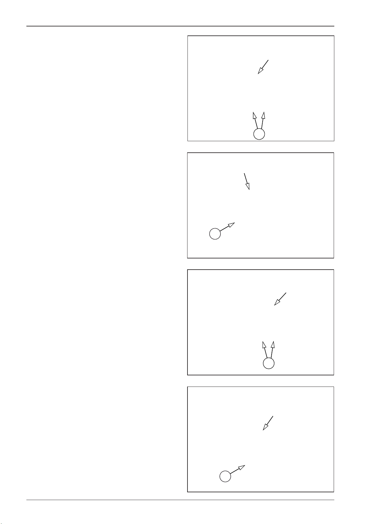
590007F
590008F
590009F
590011F
2.7 Machine operation and use
• Switch over with the UP and DOWN arrows (2) until 4–20mA
appears on the display.
Set the minimum temperature.
• Switch over with the MODE button (1) until the “u” symbol
appears on the display.
2
• Switch over with the UP and DOWN arrows (2) until the val-
ue of 32.0°F appears on the display.
Set the maximum temperature.
• Switch over with the MODE button (1) until the “n” symbol
appears on the display.
1
2
1
80 ARX 23-2 T4i, ARX 26-2 T4i
Page 85
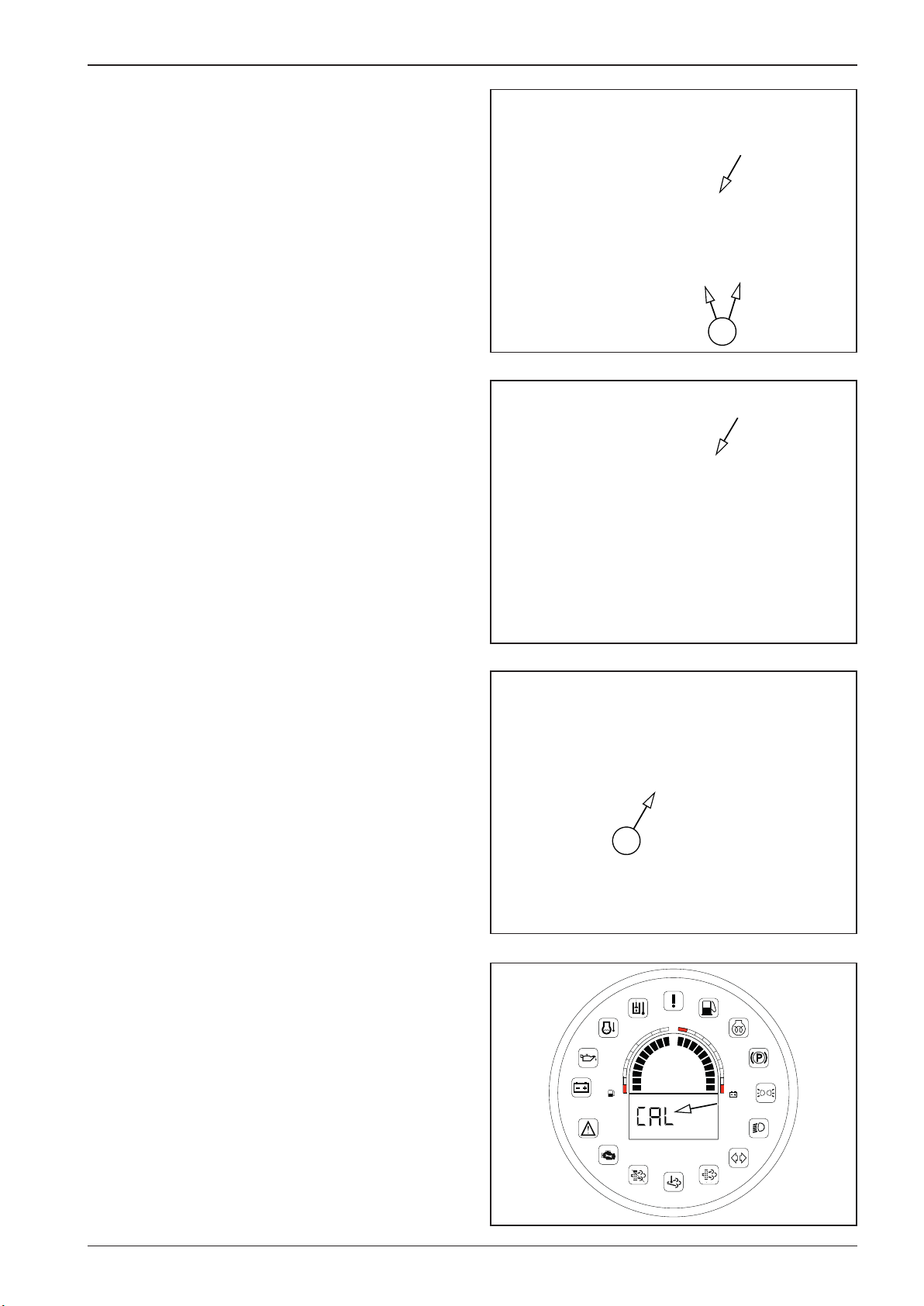
590010F
590001F
CAL003
CAL008
OPERATING MANUAL
• Switch over with the UP and DOWN arrows (2) until the val-
ue of 932.0°F appears on the display.
2
• Mount the cover.
Turn the key in the ignition box to the “I“ position.
Sit in the driver’s seat (activation of the seat switch).
Set the travel control to the parking brake position “P”.
Press the calibration button (B) for 5 seconds. While the button
is held down, the display shows the “CAL” status.
1/4
19
2/4
1
15V
3/4
13V
11V
9V
81ARX 23-2 T4i, ARX 26-2 T4i
Page 86
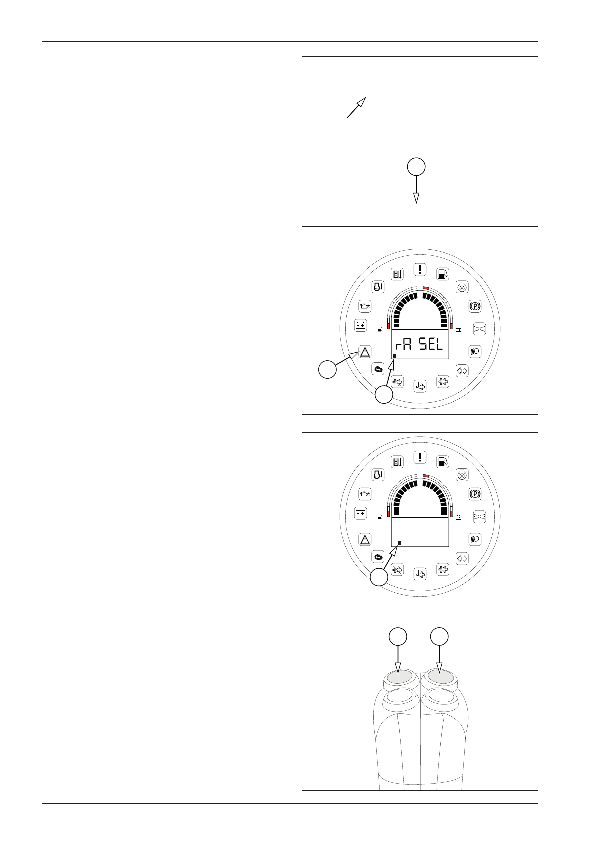
CAL002
CAL005
CAL007
CAL001
2.7 Machine operation and use
After 5 seconds, the display shows B1 and, at the same time, the
error message indicator lamp (21) starts ashing.
B
1
15V
3/4
2/4
1/4
13V
11V
9V
Using the Select button (13), scroll to the B2 tab ( Fahrenheit/
Celsius temperature unit selection) and press OK (12) to conrm.
Use the Select button (13) to set the desired unit and press OK
(12) to conrm.
21
B1
B2
1/4
2/4
3/4
tEMP
12
1
15V
13V
11V
9V
13
82 ARX 23-2 T4i, ARX 26-2 T4i
Page 87
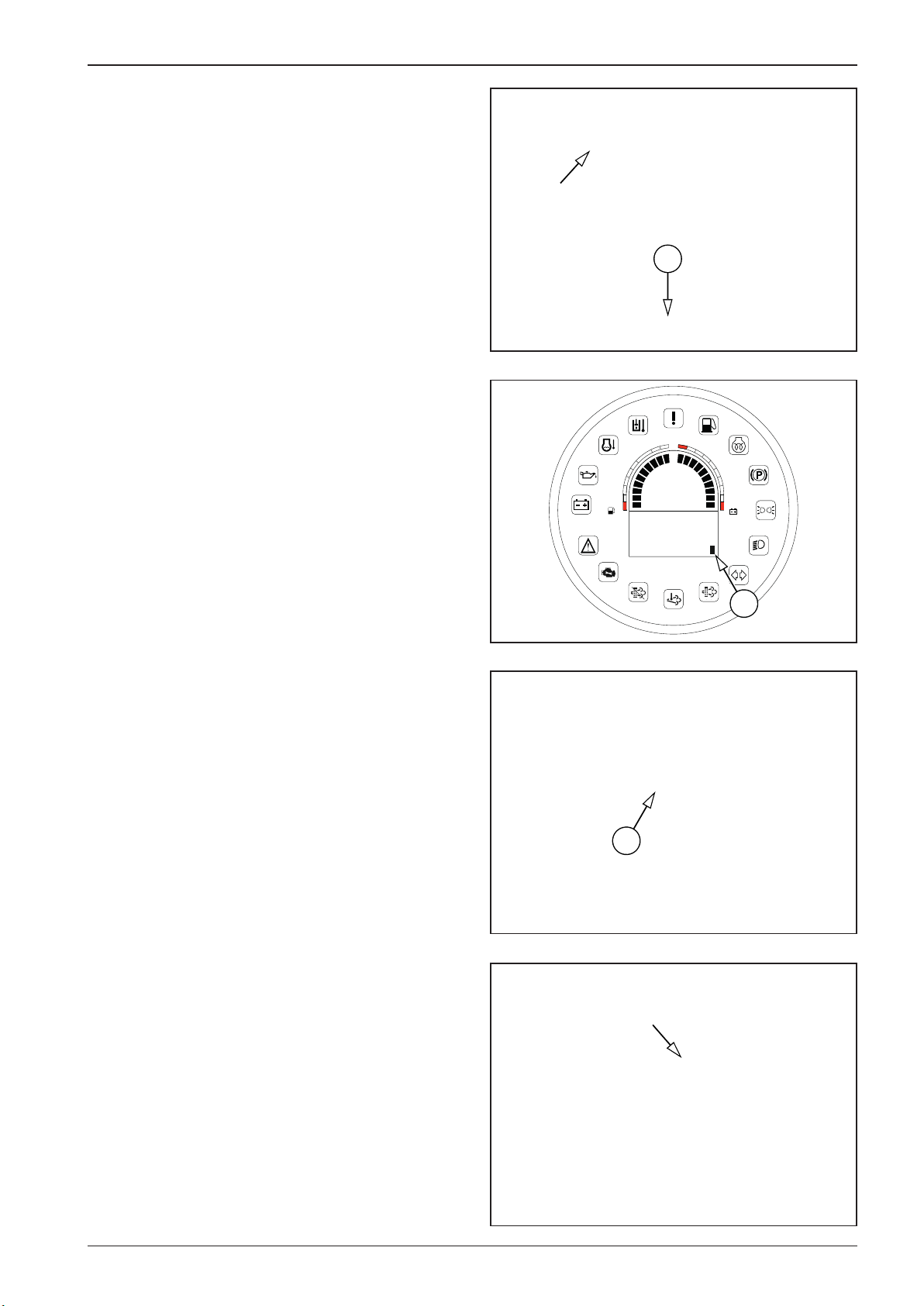
CAL007
CAL006
CAL008
590017F
OPERATING MANUAL
Use the Select button (13) to scroll to the B12 tab and press the
calibration button (B) for 5 seconds.
B
While the button is held down, the display shows the “Saving”
status.
If the parameters are OK, they are saved and the display shows
the “Saved” status.
If the set parameters are not OK, the display shows the “Error”
status. The set parameters are not saved and the whole process
must be repeated.
2/4
1/4
1
15V
3/4
13V
11V
9V
To complete the setting, switch o ignition by turning the key in
the ignition box (19) to the “0” position.
To exit the calibration mode without saving, switch o ignition
or press the calibration button for 5 seconds when the tab is not
set to B12.
Start the engine. The display will show the measured value in
degrees Fahrenheit or Celsius.
SAving
B12
19
83ARX 23-2 T4i, ARX 26-2 T4i
Page 88

589D013A
589D012
589D011
2.7 Machine operation and use
2.7.10 ROPS lifting and lowering
Only lower or raise the ROPS frame with the help of another person.
ROPS lifting
Lift the ROPS to the vertical position and mount the front screws
of the ROPS on the left and right side.
Mount the cotter pins.
84 ARX 23-2 T4i, ARX 26-2 T4i
Page 89
589D013A
589D012
589D011
OPERATING MANUAL
ROPS lowering
Remove the split pins.
Dismount the front frame screws on the left and right sides.
Tilt the ROPS safety frame to the back and secure it in asuitable
way.
Tilt and lift the ROPS with the help of another person.
There is arisk of injury from the falling ROPS.
Do not operate the machine when the ROPS is lowered.
There is arisk of fatal injury.
Lower the ROPS only during the transport.
The tightening torque of the ROPS screws is 147Nm.
85ARX 23-2 T4i, ARX 26-2 T4i
Page 90

S591000
S591001
2.7 Machine operation and use
2.7.10.1 Lowering and raising of the ROPS frame with a plastic canopy
Only lower or raise the ROPS frame with the help of another person.
It is forbidden to lower or raise the ROPS frame without
the help of another person.
Use the lowered frame only for transporting the machine. Do not operate the machine when the ROPS frame is
lowered.
Lowering procedure
Remove the screws (2x) at the bottom of the plastic canopy.
86 ARX 23-2 T4i, ARX 26-2 T4i
Page 91

S591002
S591003
S591007
589D011
OPERATING MANUAL
Release the canopy by pulling out the lever (1) slightly and lower the canopy.
1
Remove the cotter pins on the left and right side of the ROPS
frame.
Loosen the rear pegs (2) on the left and right side of the ROPS
frame by approximately two turns.
2
2
87ARX 23-2 T4i, ARX 26-2 T4i
Page 92
S591005
S591008
S591009
S591010
2.7 Machine operation and use
Remove the front pegs (3) on the left and right side of the ROPS
frame.
3
Lower the ROPS frame with the help of another person.
The frame may fall when it is being raised or lowered and
cause injury.
3
88 ARX 23-2 T4i, ARX 26-2 T4i
Page 93
S591006
S591010
S591011
OPERATING MANUAL
Insert the pegs at the top of the frame on the right and left side
and secure them with cotter pins.
Raising procedure
Remove the cotter pins and remove the front pegs (4) on the left
and right side of the ROPS frame.
Raise the ROPS frame with the help of another person.
The frame may fall when it is being raised or lowered and
cause injury.
4
89ARX 23-2 T4i, ARX 26-2 T4i
Page 94

S591007
S591008
S591009
589D011
2.7 Machine operation and use
Insert the front pegs (3) on the left and right side of the ROPS
frame.
3
Tighten the rear pegs (2) on the left and right side of the ROPS
frame.
3
2
2
Mount the cotter pins on the left and right side of the ROPS frame.
90 ARX 23-2 T4i, ARX 26-2 T4i
Page 95
S591000
S591001
S591002
S591013
OPERATING MANUAL
Release the canopy by pulling out the lever (1) slightly and raise
the canopy.
1
Mount the screws (2x) at the bottom of the plastic canopy.
The tightening torque of the ROPS screws is 147Nm.
91ARX 23-2 T4i, ARX 26-2 T4i
Page 96

TR001A
2.7 Machine operation and use
2.7.11 Telematics readiness
Global positioning system with telemetry that monitors operating systems of the machine (machine start, engine speed, fuel
consumption, number of engine hours, etc.) and its current position.
The GPS system allows the geofencing function (machine operation limited to a dened area) and remote machine monitoring, which helps nding a stolen machine.
Note
The availability and content of the given data depends on the
selected manufacturer of the telematics system.
Turn o the battery disconnector before installation or
maintenance.
TrackUnit
TU 500-4
Telematics readiness
Teltonika
TCB204
No
Telematic
Installation shall only be carried out by trained personnel according to the wiring diagram.
In case of a failure, contact your dealer or Ammann
Technical Support.
92 ARX 23-2 T4i, ARX 26-2 T4i
Page 97
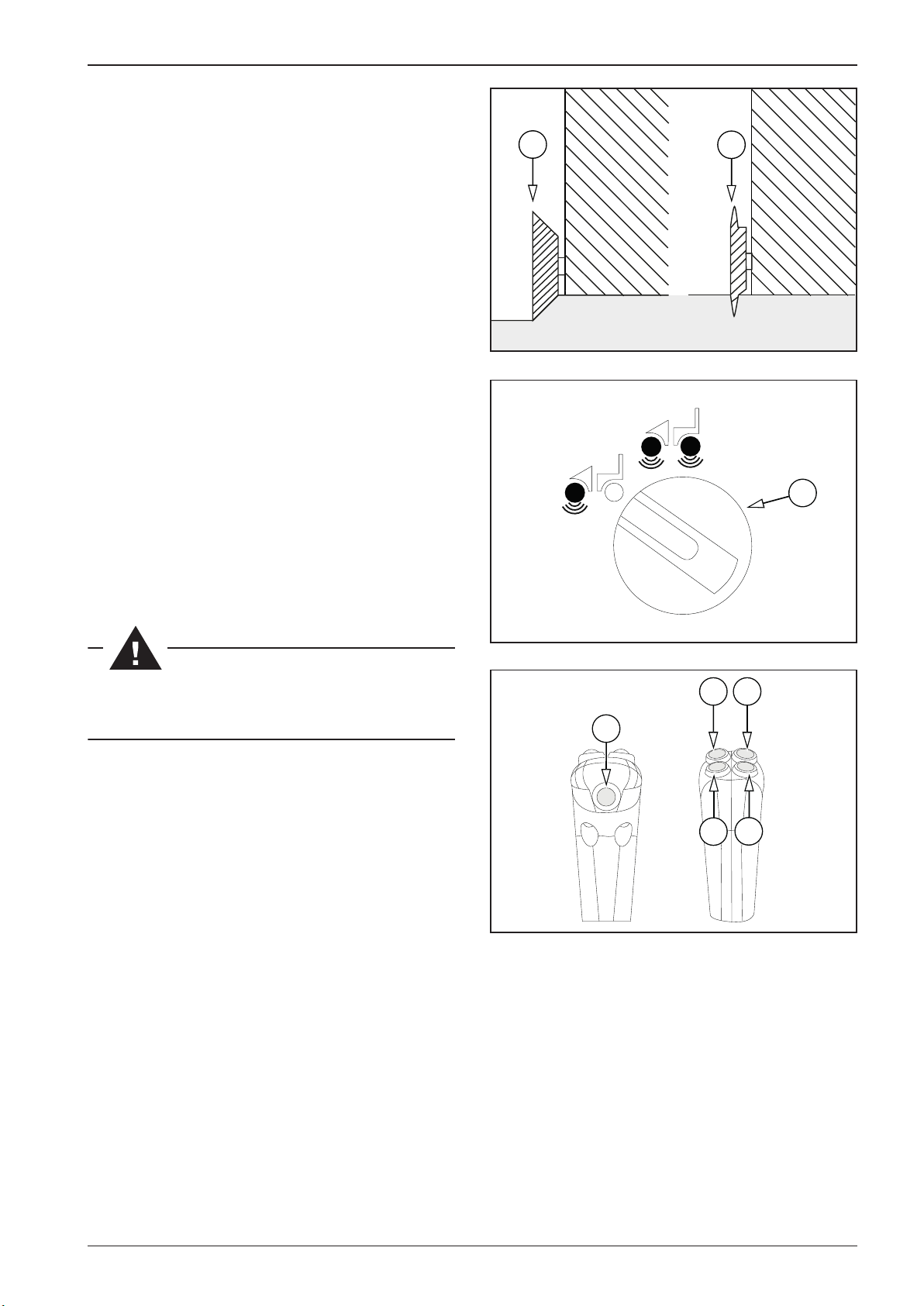
EG001
EG004
EG002A
OPERATING MANUAL
2.7.12 Edge cutter (optional equipment)
The edge cutter set contains a cutting and compaction disc.
The cutting disc (1) is used to cut the road at the desired location
and align the road edges.
The compaction disc (2) is used to nish the compaction of road
edges.
Note
If one of the discs is not in use, attach it to the holder provided.
Edge cutter pre-adjustment
Before working with the edge cutter, set the vibrating drum selector (9) to the left (front drum).
Note
The edge cutter only works awlessly with a pre-adjusted edge
cutter.
2
1
9
Control procedure
Set the desired height of the edge cutter using its up (15) and
down (16) button.
Make sure nobody is endangered when the edge cutter is
started.
Turn on drum sprinkling using the sprinkling button (13).
Turn on edge cutter sprinkling using the edge cutter sprinkling
button (14).
Note
The water inlet of edge cutter sprinkling only works when continuous drum sprinkling is on.
Turn on vibration with the vibration switch (12).
14
15
1312
16
Note
After turning on vibration, the edge cutter automatically rises
and is inoperative.
93ARX 23-2 T4i, ARX 26-2 T4i
Page 98
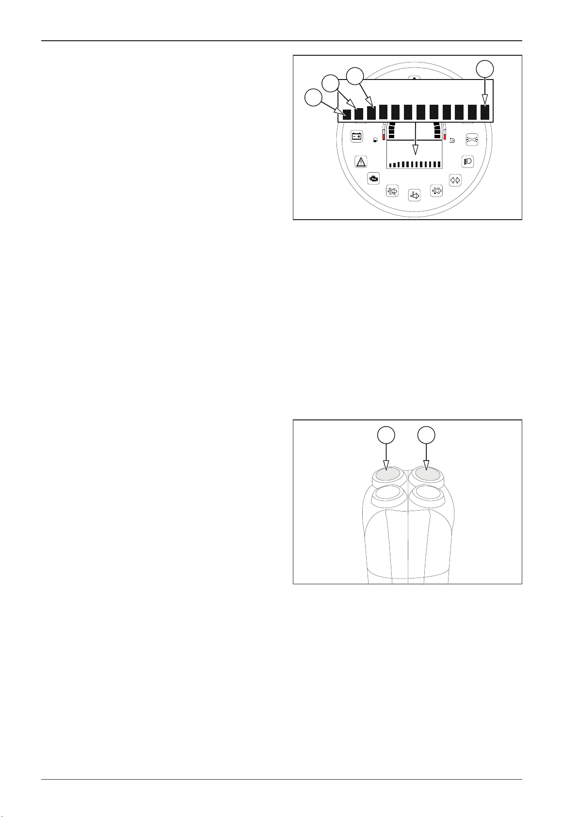
CAL009A
CAL001
2.7 Machine operation and use
2.7.13 Calibration mode
Tabs
B1 Ramp selection (rA SEL)
- selection of the Hard value
- selection of the Soft value
- return one level
B2 Fahrenheit/Celsius temperature unit selection (tEMP)
- selection of the Fahrenheit value
- selection of the Celsius value
- return one level
B3 Left lever selection (LEFtLu)
- selection of active lever
- selection of inactive lever
- return one level
B12 Save and exit (SAvE)
- Values saved
- Error saving values
B1
B2
B3
B12
1
15V
3/4
2/4
1/4
13V
11V
9V
Control
In the following text, the “OK button” means the vibration button (12). The “select button” means the sprinkling button (13).
These buttons only work on the right travel control.
Press the select button (13) to scroll through tabs B1 to B12 and
parameters of the given folders.
Use the OK button (12) to conrm your selection.
12
13
94 ARX 23-2 T4i, ARX 26-2 T4i
Page 99
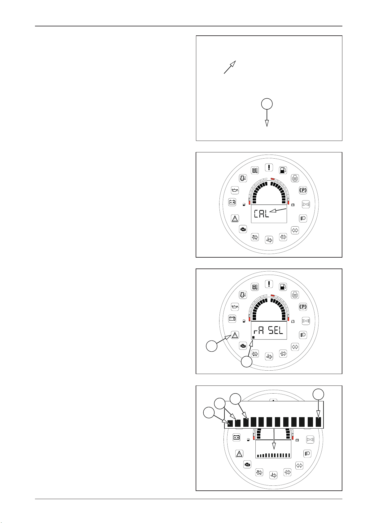
CAL007
CAL003
CAL002
CAL009A
OPERATING MANUAL
Calibration procedure:
Turn the key in the ignition box to the “I“ position.
Sit in the driver’s seat (activation of the seat switch).
Set the travel control to the parking brake position “P”.
Press the calibration button (B) for 5 seconds. While the button
is held down, the display shows the “CAL” status.
B
1
15V
3/4
2/4
1/4
13V
11V
9V
After 5 seconds, the display shows B1 and, at the same time, the
error message indicator lamp (21) starts ashing. The error message indicator lamp (21) ashes for the duration of the calibration.
Use the select button (13) to select the tab and press OK (12) to
conrm. The display will show the current state of the set parameter (e.g. SOFT when choosing the ramp – B1).
21
B1
B2
B3
2/4
1/4
B1
1
15V
3/4
13V
11V
9V
B12
1
15V
3/4
2/4
1/4
13V
11V
9V
95ARX 23-2 T4i, ARX 26-2 T4i
Page 100
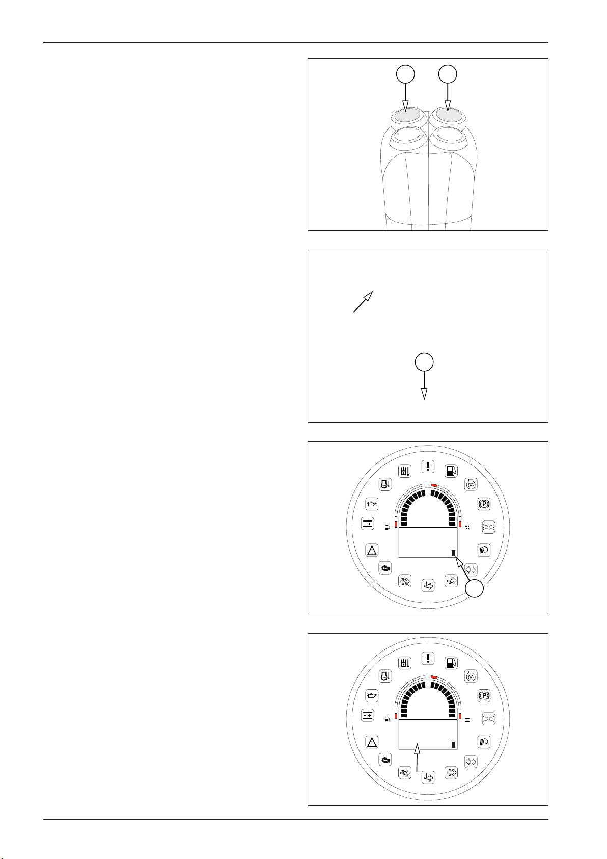
CAL001
CAL007
CAL006
CAL010
2.7 Machine operation and use
Select the parameter and press OK to conrm (12).
After all required parameters are set, set the B12 tab and press
the calibration button (B) for 5 seconds.
12
13
While the button is held down, the display shows the “Saving”
status.
If the parameters are OK, the data saved and the display shows
the “Saved” status.
If the set parameters are not OK, the display shows the “Err” status. The set parameters are not saved and the whole calibration
must be repeated.
To complete the calibration, switch o ignition by turning the
key in the ignition box to the “0” position.
To exit the calibration mode without saving, switch o ignition
or press the calibration button for 5 seconds when the tab is not
set to B12.
2/4
1/4
2/4
1/4
B
1
3/4
SAving
1
3/4
SAvEd
15V
13V
11V
9V
B12
15V
13V
11V
9V
96 ARX 23-2 T4i, ARX 26-2 T4i
 Loading...