

Page 1
®
THE INVISIBLE SPEAKER CO.
Audio for very smart homes
®
Cavity wall & Ceiling Installation guide
for Amina Edge Invisible loudspeakers
Using BackboxCV345 for Edge5i and Edge7i
Using BackboxCV300 for Edge3
V3.5 October 2019
Page 2

1
Amina Edgei Fully Concealed Loudspeakers
The Amina Edgei series of Loudspeakers
are designed to deliver best in class
audio performance in fully concealed
in-wall and in-ceiling applications,
preserving the interior aesthetic of any
space.
Featuring a unique tapered perimeter,
Amina Edge products are designed
specifically for installation using a drywall / dry lining edge fill approach. The
perimeter of the product is taped and
joined. The front surface of the speaker
is then decorated with paint, wallpaper
or fabric.
What’s in the box
The following items are included with
each Amina Edge loudspeaker -
1 x Amina Edge loudspeaker
1 x installation template/quick reference
installation guide
4 x Flange head fixing screws
1 x set 1mm shims
1 x set 2mm shims
Click to return to the contents section on page 2
Page 3

2
Contents
Caution: Read before installing this
product .....................................................................3
Environmental ........................................................5
Sound in your Home: ......................................... 6
Sound in your Work or Leisure
Environment: ......................................................... 6
Message from the Managing Director ......7
About the Manufacturer ...................................7
Introduction ........................................................... 8
Installation options ........................................ 8
Unpacking .............................................................. 8
Packaging ............................................................... 8
Compatibility ........................................................ 8
Overview ................................................................. 9
Setup tips ...............................................................10
Installation ............................................................. 12
Mounting accessories .................................. 12
Speaker protectors .......................................13
Speaker protectors .......................................14
Fixing method for BackboxCV ................ 15
Shims ................................................................... 19
Fixing shims to the speaker .....................19
Fixing shims to the BackboxCV ..............19
Alignment and preparation .........................20
Drywall / Dry line ..........................................20
Alignment required for plastering ....20
Shim sizes .....................................................20
New plasterboard walls (yet to be
plastered) .......................................................... 21
Pre-plaster the walls ................................. 21
Retrofit / pre-skimmed plasterboard..22
Retrofit alignment options .................... 22
Flush with surround .................................. 22
Flush with centre ....................................... 22
Retrofit / pre-skimmed plasterboard
(Flush with surround) .................................23
Alignment required for plastering ....23
Shim sizes ..................................................... 23
Retrofit / pre-skimmed plasterboard
(Flush with centre) .......................................24
Alignment required for plastering ....24
Shim sizes .....................................................24
Testing .................................................................... 26
Testing the speaker .....................................26
Resistance test ...........................................26
Connect the APU protection device 26
Sweep test ....................................................26
Music test ......................................................26
Problems during test ...............................26
Problems during test .................................. 27
Insecure drywall ........................................ 27
Metal studs ................................................... 27
Cable buzzing ............................................ 27
Lighting fixtures.........................................27
Finishing ................................................................28
Filling the perimeter ....................................28
Taping the joints............................................28
Feathering the panel edge ......................29
Fine surface finishing (optional) ...... 30
Decorating ............................................................. 31
Maintenance and cleaning ............................ 31
Re-decoration ...................................................... 31
Fire resisting installation ...............................32
Pre-installation checks ...............................33
Installation .......................................................34
Other fire resisting installation
methods ...........................................................40
Accessories ............................................................41
Subwoofers .......................................................41
Troubleshooting .................................................42
Advice for testing .........................................42
No or low sound output .............................42
Distortion, buzzing or rattles at
modest volumes ............................................43
Very low output after speaker passes
electrical tests................................................43
Distortion at higher volume levels .......43
Specifications .................................................... 44
Warranty information .....................................45
Copyright information ...................................45
Contact information ........................................45
Click to return to the contents section on page 2
Page 4

3
Caution: Read before installing this product
This manual contains detailed instructions required to install your Amina Edge Invisible
Loudspeaker into a cavity wall using a BackboxCV housing or simple mounting blocks.
CAUTION:
The installation guide included with
a BackboxCV describes the different
installation steps required for other models
of Amina Invisible loudspeakers. Refer only
to the Installation steps in this guide when
installing an Edge loudspeaker.
WARNING:
No attempt should be made to install
a BackboxCV within existing building
structures unless you are certain that no
electric cables, water pipes, gas pipes or
supporting joists will be cut through.
FIRE PROTECTION:
When making an intrusion into an
internal wall or ceiling to install an
Amina loudspeaker be sure to check
the appropriate regulations pertaining
to the required fire rating. Depending
on the location of the intrusion and
the applicable regulations it may
be necessary to build in or install
additional fire rated components or
products to surround the speaker
and back box. Amina Technologies
take no responsibility for the correct
specification and installation of any such
fire protection system that is required
behind their loudspeakers.
METAL FRAME CEILINGS:
When installing in metal frame (MF)
ceilings (& walls), please ensure the
assembled metal frame is fully solid and
secure and that all metal mating joints are
mechanically fixed or bonded together.
Metal joints that are not tightly fixed
have the potential to generate spurious
buzzing noises as the two free edges rub
against each other when activated by the
acoustic energy generated by the Amina
Loudspeaker. All debris, loose screws,
excess materials etc, should be removed
from above the ceiling to avoid unwanted
rattles.
CLEANLINESS DURING
INSTALLATION:
Always install the speaker when the general
environment is clean and dust free. Keep
each speaker protected in its shipping
carton until cutting work is complete and
the installation room has been cleaned
down thoroughly. Never expose the rear
of the loudspeaker to an environment
containing airborne metallic particles
and dust, as these will be attracted to the
speakers high power magnet causing
damage to the loudspeaker.
FIRE RESISTING INSTALLATION:
NOTE: Where building regulations state
that an installation must comply with fire
resisting standard BS476 Pt. 21: Timber
floors, refer only to the instructions in
the Fire Resisting Installation section on
pages 31-38.
Click to return to the contents section on page 2
Page 5

4
Caution: Read before installing this product
SPEAKER PROTECTION:
Amina loudspeakers should be installed
with an APU or other suitable electrical
overload protection device. These
devices help ensure the loudspeaker
operates reliably for many, many years
ahead, by limiting and protecting against
temporary excessive audio signals that
could damage the product.
Common sense should always prevail
though. Your product should never be
operated at repeated or consistently
excessive audio levels. Never operate
your Amina speakers at a level where
audio reproduction appears distorted.
For the ultimate in protection,
Amina recommend using the Amina
A100Q digital amplifier to drive your
loudspeakers. It prevents unwanted
and excessive electrical energy from
reaching the speaker whilst allowing it to
perform at its very best at all times.
Please read carefully before installing
this product
• To ensure correct installation, please
read this guide carefully and keep in
a safe place for future reference.
• Install this product in a cool, dry,
clean place - away from direct
sunlight and heat sources, vibration,
chemical fumes, dust and moisture
(steam).
• Do not expose this product to sudden
temperature changes or locate it in
an environment with high humidity.
This is to prevent condensation
forming inside which may cause
damage to the product.
• Do not clean this product with
chemical solvents as this may cause
damage to the finish. Use a clean, dry
or damp cloth.
• After installation, avoid pushing
on the wall or ceiling surface
immediately in front of the speaker.
Excessive excursion can crack the
plaster around its perimeter and can
damage the loudspeaker.
• Do not attempt to modify or repair
the product. Contact your distributor
or Amina if a fault should occur.
• The rear of the product should not
be subject to chemical cleaning and
should not be painted in any way.
• Ensure that all installation mounting
surfaces are able to support the
weight of the BackboxCV with that of
your chosen speaker.
• You will require a minimum
cavity depth of 75mm behind the
plasterboard to allow the use of a
BackboxCV.
Click to return to the contents section on page 2
Page 6

5
Environmental
• Before installing, ensure that the
building is environmentally sealed,
de-humidified to a maximum of
RH50%, and at a stable temperature
of at least 16 degrees centigrade (61
degrees Fahrenheit)
• This product should not be used with
single thick coat plaster solutions or
with other finishing methods that take
days (rather than hours) to dry out.
• Please be aware that when this
product is directly fitted into a
solid brick, block or concrete wall
structure (e.g. when using the solid
wall backbox) vibrational energy is
inevitably transferred into the solid
wall structure. This energy can travel
for some considerable distance up,
down and along the structure. It is
therefore recommended the product
be fitted within acoustically isolated
stud walls or ceiling sections where
possible. The use of the product
directly embedded in solid walls is
not recommended in multi occupancy
buildings.
• Please be aware that when this
product is fitted in simple (stud or
rafter with plasterboard/floorboard
attached on either side) stud
walls or wooden rafter ceiling/
floor structures, vibrational energy
is inevitably transferred into the
building structure. This energy can
travel for some considerable distance
up, down and along the structure. It is
therefore recommended the product
be fitted within acoustically isolated
stud walls or ceiling sections where
possible. Special care should be taken
when installing the product in multi
occupancy buildings.
• Completed and fully dried plaster
surfaces should be finished with
permeable coatings / materials,
to allow moisture in that coating
or the adhesives used to apply
those materials, to dry into the
environment, rather than trap
moisture in the speaker.
• During installation take care to use
appropriate and suitable joint filling
compounds to fill the gap between
speaker and the surrounding surface.
This gap should be no less than 2mm
and no more than 5mm in width.
Inappropriate compounds used in
such a joint can shrink and crack
excessively and lose strength.
Allow the joint to dry thoroughly
before applying surface skim coats,
as shrinking in the joint depth whilst
drying could create a very slight
embossed outline in the finished and
decorated surface.
• As a general rule in the construction
industry, any drying process should
be gradual rather than forced with
excessive heat otherwise materials
can lose strength and can crack.
• Amina Technologies take no
responsibility for inappropriate use
of materials and environmental
conditions under which they are
applied.
Click to return to the contents section on page 2
Page 7

6
Sound in your Home:
Amina products are widely applied
in whole house audio systems and
multichannel home cinemas to create the
very best entertainment source whilst
not impinging on the design of your
home.
Never imagine though that sound
reproduction is isolated to one room only
and will not be heard elsewhere in the
home. Sound from any audio source (a
person talking, a conventional speaker,
a TV or an Amina speaker) will transfer
in air through open doors, ventilation
structures, gaps under doors etc, to
other areas of the house. Sound will also
pass mechanically through the structure
of the building (a good example is the
central heating boiler. Most homeowners
know exactly when it is on!) to other
areas quite some distance away.
Sound in your Work or Leisure Environment:
Amina products are widely applied in
prestigious retail, hotel, restaurant, office,
spa and other leisure facilities.
The Amina Active Sound Board
technology creates an incredibly even
level of sound across an entire space.
This creates an entertaining yet naturally
comfortable sound field for users and
occupiers.
At the same time the physical
embodiment of the speaker is totally
unobtrusive, allowing interior designers
complete freedom from technology.
Whole house/multi-room audio systems
are designed to give you the very best
audio experience in the space/room you
might occupy at any one moment. This
does not mean to say that occupiers of
other rooms will not hear some of that
sound at the same time. They are more
than likely to experience it in some lesser
level and lesser quality than the intended
room.
Please remember therefore that it is
not always possible to enjoy the full
capabilities of your audio system when
other members of the household want to
remain undisturbed.
Click to return to the contents section on page 2
Page 8

7
Message from the Managing Director
Congratulations and thank you for
purchasing an Amina Technologies high
performance invisible loudspeaker.
At Amina we are proud of being at the
forefront of flat panel Active Sound
Board loudspeaker technology. All
the components that make up your
loudspeaker have been developed
specifically to provide the ultimate
in sound quality and reliability, whilst
allowing you to decorate, furnish and
enjoy your home in any way you wish
without any visible ‘clutter’ created by
your audio system.
At the heart of an Amina loudspeaker is
our high performance vibrational panel
driver, featuring a unique high power
neodymium magnet motor system. This
enables the product to provide high
quality, high loudness levels from such a
compact design. Please take a moment
to read this guide which will help you
achieve the best possible performance
from your product.
About the Manufacturer
Amina Technologies Ltd is the world’s
leading designer and manufacturer of
truly invisible loudspeaker solutions.
Our flat panel loudspeakers have been
used in a wide range of both commercial
and residential applications for over
seventeen years.
Luxurious hotels & spas, exclusive retail
outlets and stunning private residences
have all benefitted from using Amina
invisible loudspeakers, not only for
its’ incredible aesthetic quality, but
for its’ absolute ability to reproduce
sensationally clear audio across any
space. Amina has created the very best
discrete audio solution for architects,
interior designers and design conscious
clients.
See our website for more details about
Amina and a selection of prestigious
projects completed using our products.
Thank you and enjoy listening.
Richard Newlove
MD - Amina Technologies Ltd
Click to return to the contents section on page 2
Page 9

8
Introduction
Thank you for purchasing Amina Edge
invisible loudspeakers. Properly installed,
these loudspeakers will provide high
quality sound for many years, even
decades, to come.
Installation options
Installation is simple, but should only
be attempted by professional building
trades with plastering experience
and who have completed an Amina
installation training course.
Amina loudspeakers can not be mounted
into a wall without the correct fixing
accessories, supplied by Amina for each
wall type.
Please read the instructions carefully,
particularly the Installation section which
contains important advice to select the
correct wall-mounting accessories.
Packaging
CAUTION:
Take care when removing the
loudspeakers from the carton.
The packaging for Amina Edge
loudspeakers has been carefully
designed to protect the product during
transit. Please retain it in the unlikely
event you need to return the product to
your dealer or to Amina. Please recycle
the packaging should you wish to
dispose of it.
The outer carton is made up of 80%
recycled board.
Compatibility
This installation guide covers installation
of -
This manual should then be read in
conjunction with the associated manual
supplied with your mounting accessory.
Unpacking
Unpack the unit.
Check that your carton contains the
correct number of items - a single
speaker, or two if ordered as a pair.
Retain this Installation Guide. If you pass
the unit on to a third party make sure
you pass on the Installation Guide.
Amina Edge5 and Edge 7 Invisible
loudspeakers within a BackboxCV345.
Amina Edge3 Invisible loudspeakers
within a BackboxCV300.
Installation of any Edge loudspeaker
using basic fixing blocks.
If you are installing a BackboxCV with
any other type of Amina Invisible
loudspeaker, refer to the General
Installation guide supplied with the
BackboxCV that covers all other
loudspeaker models.
Click to return to the contents section on page 2
Page 10
9
c
b
b
d
b
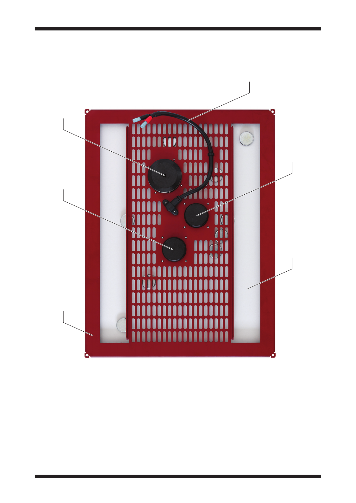
Overview
a
1. Electrical connection (to an amplifier, via APU)
2. High power neodymium magnet structures
3. Active panel surface
4. Aluminium chassis
Click to return to the contents section on page 2
Page 11

10
Setup tips
APU protection
Amina loudspeakers must be used with
an APU protection device or another
protection device, approved by Amina.
Please refer to the instructions supplied
with the APU devices and full warranty
information for further details.
Installation Backboxes
Amina Edge loudspeakers have
been designed for optimum sound
quality when installed with the Amina
BackboxCV. We recommend that they
are used wherever possible in a cavity
type installation. If our basic fixing block
kit is used you may find that the low/
mid frequencies are reproduced less
accurately, but any effect will be very
much installation specific.
Wall or Ceiling Placement
Amina loudspeakers are suitable for
both wall and ceiling installations. When
the most uniform audio coverage in a
room is required, space the loudspeakers
evenly in the ceiling. However, if the room
has a height greater than 6m (19’), Amina
suggests installing them in the walls at a
height of around 1.8m (6’).
When installed into solid walls or ceilings
using the Amina BackboxSW, you may
find that your speaker reproduces
slightly less low frequency output
compared to a BackboxCV installation.
Also, depending on the building
construction, there may be significant
mechanical sound transmission into
adjacent rooms/properties (see page 5).
Audio Characteristics
Amina loudspeakers generate sound
in a similar way to an acoustic musical
instrument. The speaker’s front face is
effectively the “musical” soundboard and
the sound waves generated from it are
diffuse and are dispersed over a very
wide angle. This means that loudspeaker
positioning is far less critical than with
conventional loudspeakers. Additionally,
just like the acoustic musical instrument,
Amina loudspeakers have excellent room
filling abilities.
Amina loudspeakers are planar devices
and this feature is further enhanced
when flush mounted into your wall or
ceiling. Being planar (or flat) means
that the audio’s arrival time to the
listener is the same for all frequencies,
i.e. there is very little phase distortion.
Therefore Amina loudspeakers (and other
planar devices such as electrostatic
loudspeakers) can reproduce subtle
nuances on a recording with incredible
accuracy.
In addition to the above characteristics,
the radiating surface of an Amina
speaker is very stiff and undergoes very
small amounts of movement in order
to generate high sound pressure levels.
This means that the loudspeakers are
inherently “fast” making them highly
articulate loudspeakers.
In dedicated listening rooms where
loudspeakers are used in stereo or
multi channel systems, position them
in the walls so that the centre point
of the speaker is approximately 1 –
1.8m (3.5 - 6‘) from the floor. This will
give excellent results, but don’t worry,
if this is not possible to achieve in
your room, the audio characteristics
of Amina loudspeakers make exact
positioning according to stereo, 5.1 and 7.1
conventions far less critical.
Click to return to the contents section on page 2
Page 12
11
Setup tips
Speaker Orientation
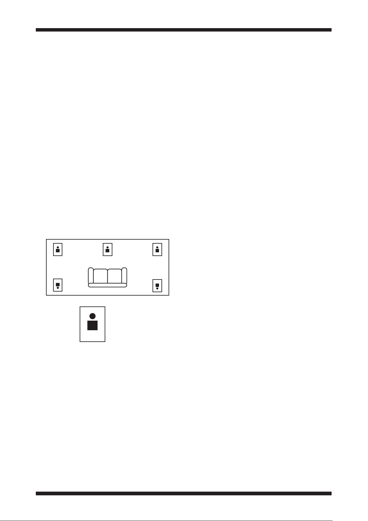
Amina loudspeakers can be installed
either in portrait or landscape
orientations. Typically the spacing
between wall joists will dictate portrait
orientation and Amina have optimised
the dispersion characteristics for this
setup. Therefore when installing into
walls Amina suggest portrait orientation
for best sound quality.
For non-critical listening in ceiling
installations the orientation of the
speaker is not crucial.
For critical listening in ceilings, e.g. a
5.1 surround system, ensure that the
orientation of all loudspeakers are the
same relative to the main listening
position and position the top of the
speaker closer to the wall/ceiling
boundary.
System Requirements
From a system compatibility point of view
your speaker (and it’s accompanying
APU protection unit) can be treated like
any conventional low impedance (4-8
ohm) loudspeaker. Amina recommends
you use a good quality amplifier so as
to avoid driving them with high levels
of distortion, which at best, will provide
poor sound quality and at worst may
permanently damage the loudspeaker.
Amina also recommend you connect
your loudspeakers to your amplifier
with at least 16AWG OFC (oxygen free)
cable (14AWG for long runs) to avoid
any chance of reduced efficiency and
restricted audio bandwidth.
For 2.1, 5.1, 7.1 and other multi-channel
systems, always use the amplifier’s
crossover settings to divert frequencies
below 100Hz to your subwoofer. This will
improve the dynamic range and power
handling of the system. (APU devices
should still be used).
top
Bottom
Boundary Loading
It is possible to increase the low
frequency output of Amina loudspeakers
by positioning them close (50mm
- 150mm) to the corners of a room.
This can be useful when no additional
subwoofer (e.g. ALF80 or ALF120) is used.
IMPORTANT: Amina loudspeakers are
highly revealing of any shortcomings in
the source or amplifier. Please be aware
that some low cost zone amplifiers will
produce high amounts of distortion well
within their operating range and this
will be ruthlessly revealed by Amina
loudspeakers.
Sound Transmission
As with any speaker designed to be fixed
to a structure within a wall or ceiling,
careful consideration should be given to
sound transmission into adjacent rooms
or properties. We recommend specialist
advice is taken if sound transmission into
adjacent rooms needs to be minimised.
Please talk to the Amina technical team
for advice on reducing sound transmission
as a starting point.
100/70V Option
For multi-speaker commercial
installations, please contact Amina for
their range of loudspeakers supplied with
100V or 70V line transformers fitted.
Click to return to the contents section on page 2
Page 13
12
Installation
IMPORTANT: Read this section carefully before attempting to install an Amina Edge
loudspeaker.
To avoid any possible damage to Amina invisible loudspeakers they must be mounted
and connected using the correct accessories, supplied by Amina. The tables to follow
list these accessories.
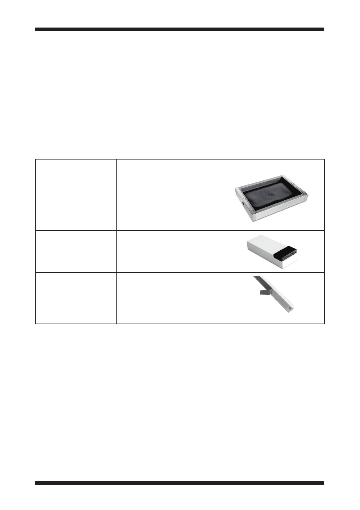
Mounting accessories
Identify the construction type of the wall/ceiling where the loudspeakers are to be
installed and ensure you have the correct fixing accessories to hand before installing
your loudspeakers.
Full installation instructions are included with each type of mounting accessory.
Typ e Application Image
BackboxCV345
BackboxCV300
For cavity walls and
ceilings
Basic fixing block kit
For cavity walls
Shims
Refer to the Installation guide supplied with the above mounting accessories for
detailed fitting instructions of the accessory together with how the loudspeaker is used
within it.
Used to install Edge
loudspeakers in cavity
walls and ceilings to reduce
airborne sound generation
from the rear of the speaker
and create optimum
acoustic cavity.
Used to install Edge
loudspeakers in cavity
walls and ceilings, when
BackboxCV cannot be used.
Various thicknesses
available to align the
speaker with the front of
non-standard plasterboard
structures or for retrofit
installations.
Click to return to the contents section on page 2
Page 14

13
Installation
Speaker protectors
Amina APU series speaker protectors are
specifically designed to work with Amina
invisible loudspeakers. They provide
essential safe operating functions
and include protection elements that
constantly monitor the power fed to
the speaker keeping it within safe limits
should the need arise.
An Amina speaker protector should be
wired in-line with each Amina speaker,
preferably in an accessible place,
allowing this device to be replaced as
necessary.
APU devices are designed to
work with a single speaker. Never
connect more than one speaker
onto a single APU protection
device.
However, common sense should always
prevail. Your product should never be
operated at repeated or consistently
high audio levels. Never operate your
Amina speaker at a level where audio
reproduction appears distorted.
For the ultimate in protection and
performance, use the Amina A100Q
multi-channel amplifier.
Refer to the table on the next page for
more detail of protection options for
short to medium periods of time.
Click to return to the contents section on page 2
Page 15
14
Installation
Speaker protectors
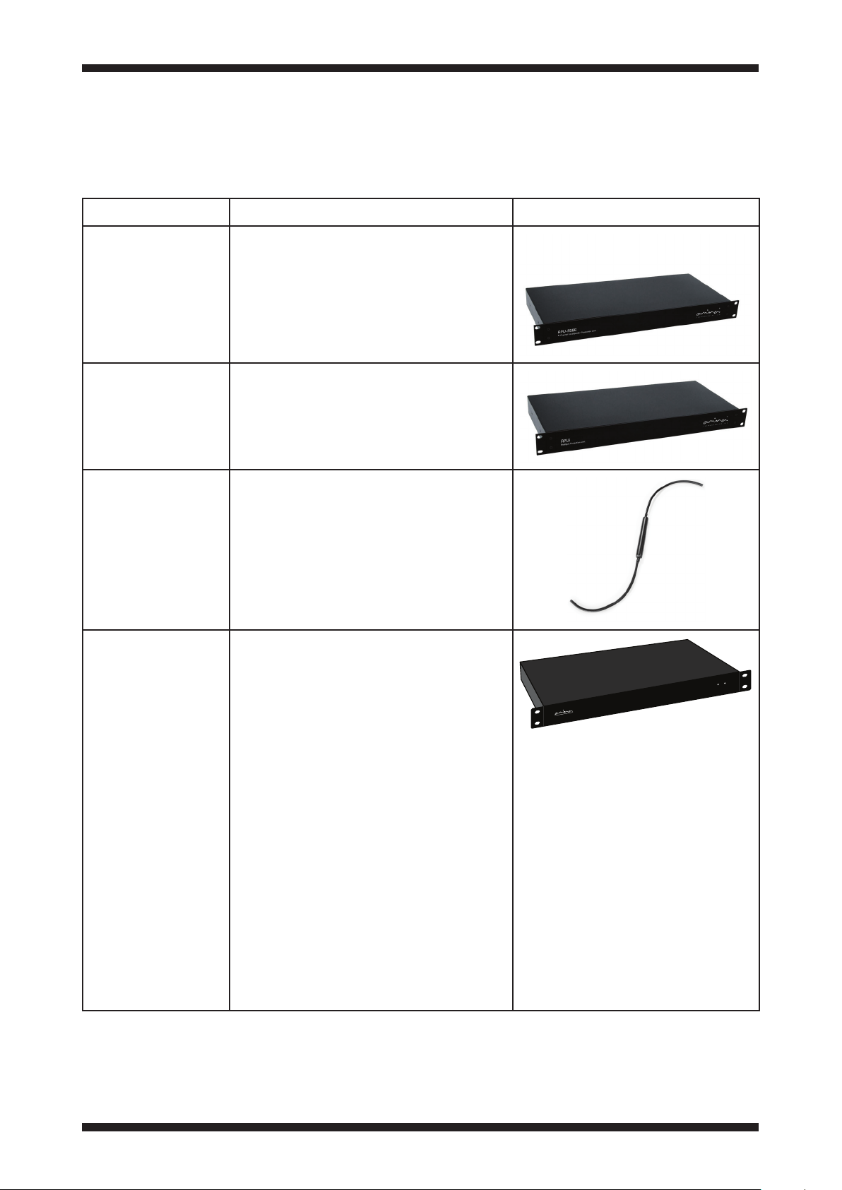
There are four types of protector.
Typ e Application Image
APU-RS8iC
APU-RS16iC
APUiC
A100Q amplifier
Ultimate
speaker
protection
Flexible 8 channel crossover and
protection unit in a 1U case for
optional rack mounting. Provides
protection for installations of up
to 8 Amina Edge loudspeakers of
any type.
16 channel crossover and
protection unit in a single 1U case.
Provides protection for up to 16
Amina Edge loudspeakers of any
type.
Single channel crossover and
protection for wiring in-line with
each Amina speaker.
APUiC crossovers are available
in different versions and must be
ordered to match the speaker
being installed.
Absolute protection of a
loudspeaker is possible by
sensing and controlling output
voltages within the amplifier
driving that loudspeaker. The
Amina A100Q amplifier integrates
clean and powerful amplification
(4 channels at 100W each) with
sophisticated digital sensing and
control technology to deliver the
ultimate protection for your Amina
invisible speaker. It both prevents
excessive audio signals from ever
reaching the speakers whilst
allowing them to perform at their
absolute peak at all times. This is
achieved thanks to some clever
internal digital signal processing
software that knows exactly how
to get the best from each speaker.
®
.
O
C
ER
K
LE SPEA
ISIB
V
E IN
TH
Click to return to the contents section on page 2
Page 16
15
Installation
Fixing method for BackboxCV
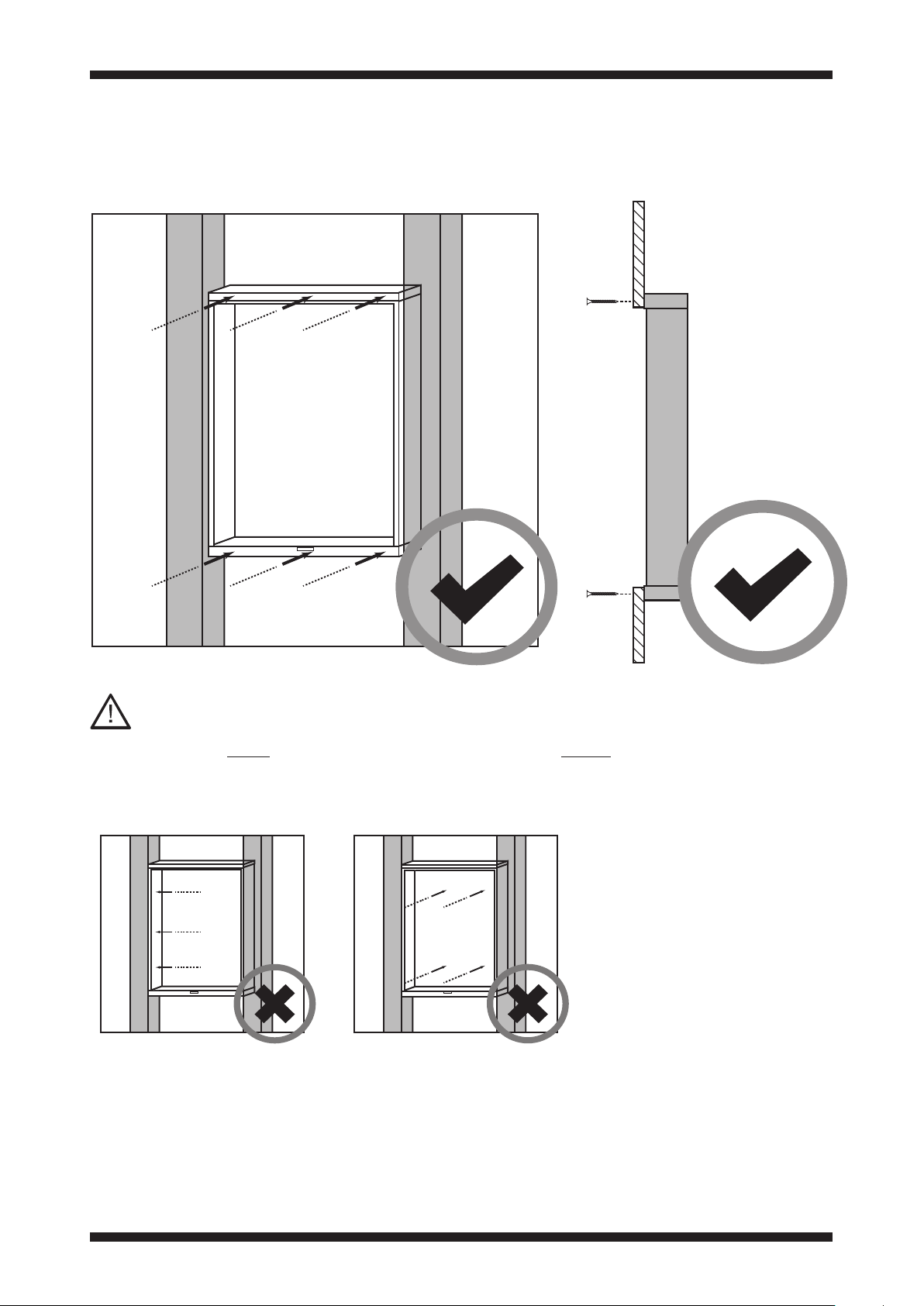
IMPORTANT:
The BackBoxCV must be fixed to the plasterboard only. Never attach directly to the
stud work or near supporting structure as shown in the images below.
Click to return to the contents section on page 2
Page 17

16
Installation
Locate joist work
When you have chosen your speaker
locations, before cutting into the
plasterboard it is important that you
locate the position of the wall studs.
Ensure the spacing between them is at
least 5mm greater than the width of your
Amina Edge speaker.
If necessary cut an inspection hole in
the plasterboard, use a tape measure
inserted through the hole to accurately
locate the edges of studs.
cut a small
hole in plasterboard
to check stud location
350mm (CV345)
305mm (CV300)
(minimum)
Click to return to the contents section on page 2
Page 18
17
IQamina-spacesaver.pdf 1 29/10/2013 16:42:02
Installation
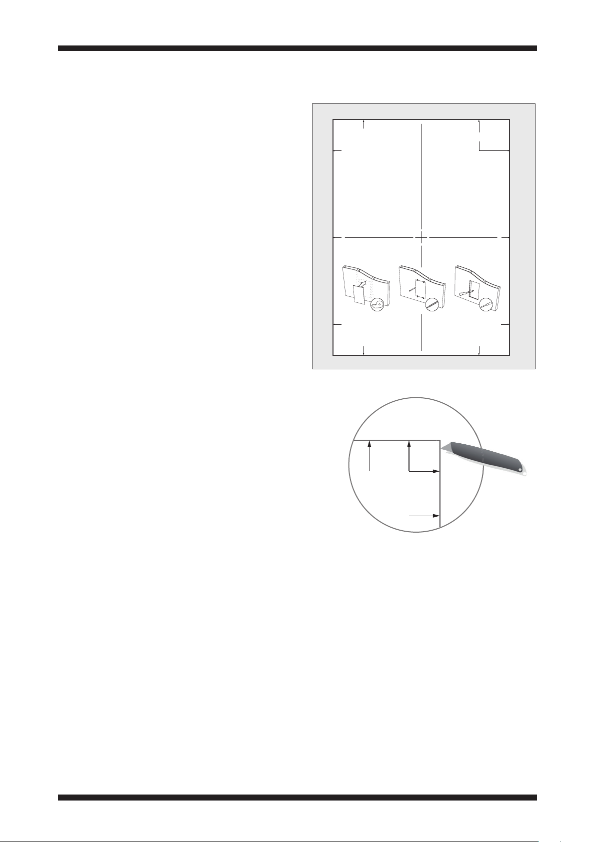
Using the Cutout Template for
pre-install of BackboxCV
Staple or tape to plasterboard/drywall to
act as a template.
Invisible Loudspeaker
Cutout Template
Hole Size (WxH): 12” [305mm] X 15 15/16” [405mm]
CUT HOLE THIS SIZE
Using the Cutout Template
1. Ascertain joist position behind
plasterboard/ drywall.
2. Ensure cut out dimensions fit between
the joists.
3. Use a knife to cut around the outside
of the template.
cut along
edge
Click to return to the contents section on page 2
Page 19

18
Installation
Installing the BackboxCV
Create 455 x 350mm (17
aperture (CV345).
Create 405 x 305mm (15
aperture (CV300).
Using a sharp knife or pad saw, cut an
aperture in your plasterboard wall or
ceiling. Ensure the aperture is created
between supporting joists or stud work.
We strongly advise that joists are not
cut to make space for the backbox. Any
activity of this sort may well influence
the structural integrity of your property.
7
/8” x 13 3/4”)
7
/8” x 12”)
sharp knife
pad saw
IMPORTANT:
Double check the size of the aperture,
as this is important further on into the
installation process.
Click to return to the contents section on page 2
Page 20
19
Installation
Shims
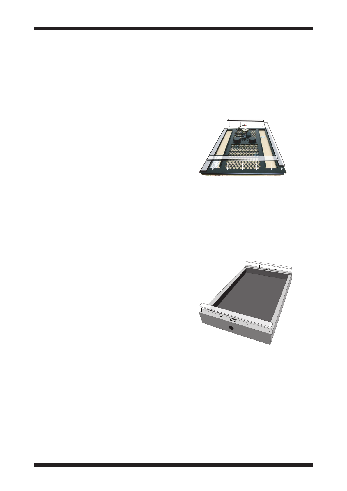
Once the hole is cut for the BackboxCV it
is important to identify the construction
of the wall and its thickness.
You may need to fix shims to the speaker
frame or to the BackboxCV to correctly
align the speaker.
The thickness of the shims required is
shown in the alignment guide to follow
and will depend on the construction of
the wall and the thickness of plaster skim
(if any).
Fixing shims to the speaker
Some installations will require shims
fixed to the speaker mounting face to
compensate for the thickness of plaster
skim. This arrangement is shown below.
Fixing shims to the BackboxCV
Some installations will require shims
fixed to the BackboxCV mounting face
to compensate for thinner drywall or
plasterboard. This arrangement is shown
below.
Click to return to the contents section on page 2
Page 21
20
Alignment and preparation
Drywall / Dry line
For new drywall walls /ceilings
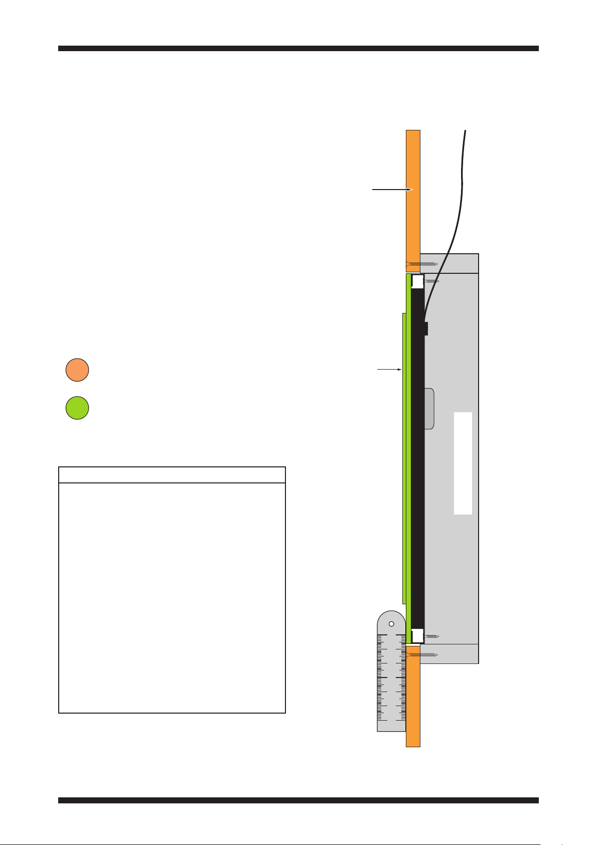
Alignment required for plastering
The diagram shows an Edge speaker
fitted into a BackboxCV in a new drywall
construction (not skimmed).
When correctly installed, the outer edge
of the speaker panel will align with the
drywall surface around the speaker and
the raised centre section of the speaker
panel will sit 0.8mm (
1
/32”) in front of the
drywall.
Drywall
Speaker panel
12.5mm (1/2”)
drywall
raised section
of speaker
panel
Shim sizes
Standard 12.5mm (
1
/2”) drywall
No shims are required for installation in
12.5mm (
1
/2”) drywall. For other drywall
thicknesses, shims will be necessary.
Thicker drywall
For thicker drywall, subtract
12.5mm (
1
/2”) from the thickness of the
drywall to determine the shim size. Fix
the shims to the mounting face of the
speaker.
Thinner drywall
For thinner drywall, subtract the
drywall thickness from 12.5mm (
1
/2”) to
determine the shim size. Fix the shims
to the mounting face of the BackboxCV.
BackboxCV345
Click to return to the contents section on page 2
Page 22

21
Alignment and preparation
New plasterboard walls (yet to be plastered)
For new plasterboard walls /ceilings that have not yet been plastered.
Pre-plaster the walls
When working with new plasterboard
walls it is advisable to completely plaster
the wall and allow it to dry fully before
starting work to install the speaker(s).
12.5mm (1/2”)
plasterboard
The diagram on this page illustrates a
wall prepared in this way.
Once dry, follow the instructions from
pages 16 - 18 to locate joists, then cut an
aperature for the BackboxCV.
The BackboxCV and speaker can then
be fitted by following the Retrofit/Preskimmed installation instructions on
pages 22-24.
Plasterboard
Plaster
plaster skim
Click to return to the contents section on page 2
Page 23

22
Alignment and preparation
Retrofit / pre-skimmed plasterboard
For walls /ceilings that have already been plastered.
Retrofit alignment options
The unique design of the Edge
loudspeaker allows a choice of two
alignment options when retro-fitting an
Edge speaker and BackboxCV into a
plastered wall.
Flush with surround
You can choose to align the surround of
the speaker panel to the plaster surface
as shown here.
Flush with centre
Alternatively, you can adjust the shims
to set the speaker further back in the
BackboxCV to align the raised section of
the speaker panel to the plaster surface.
With this type of installation, remove
approximately 25mm (1”) width of plaster
around the perimeter of the opening to
allow space for joint tape.
The next two pages show more detailed
drawings of these two methods of
installation.
Click to return to the contents section on page 2
Page 24
23
Alignment and preparation
Retrofit / pre-skimmed plasterboard (Flush with surround)
For walls /ceilings that have already been plastered.
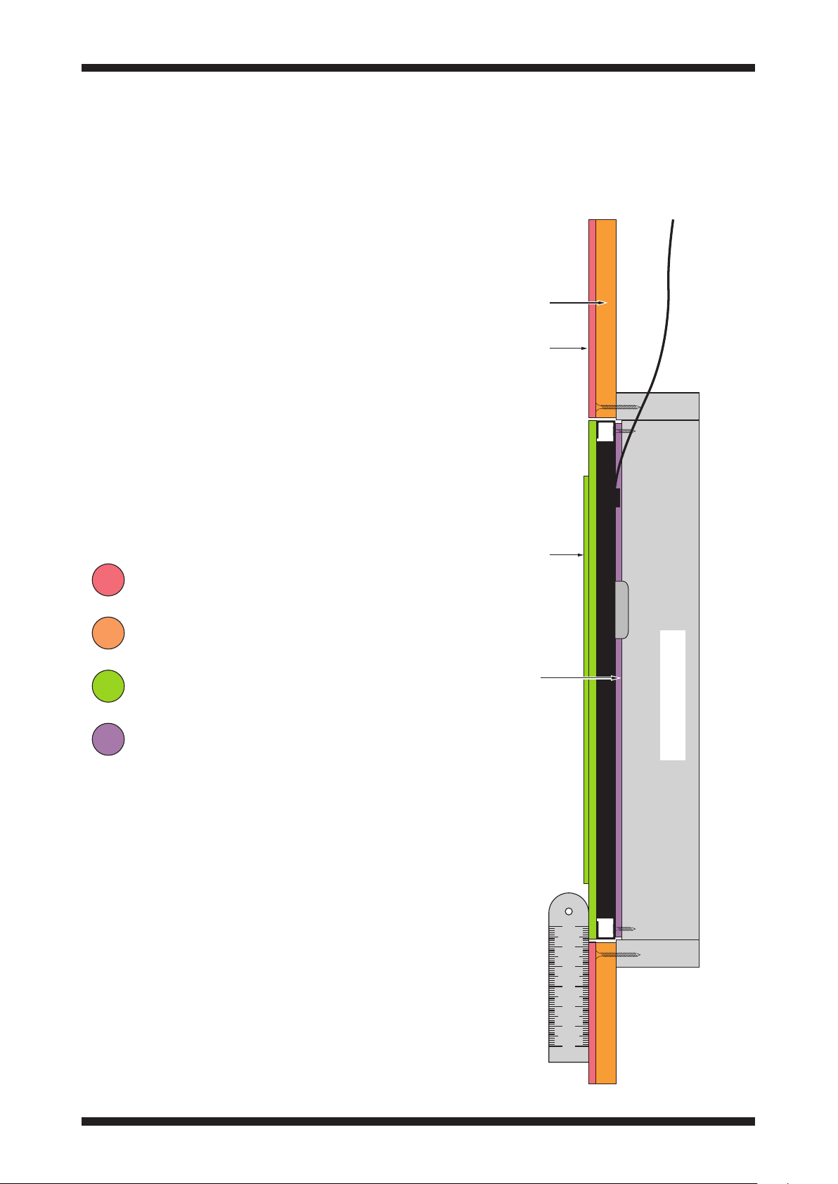
Alignment required for plastering
The diagram shows an Edge
speaker fitted into a BackboxCV in
a pre-skimmed wall constructed of
plasterboard.
When correctly installed, the outer edge
of the speaker panel will align with the
plaster surface around the speaker and
the raised centre section of the speaker
panel will sit 0.8mm (
plaster surface.
To achieve this alignment, shims of the
correct size are required when fitting an
Edge speaker into a BackboxCV.
1
/32”) above the
plasterboard
existing
plaster
Plaster
Plasterboard
Speaker panel
Shim
Shim sizes
Shims will be required to space the
speaker out to meet the face of the
plastered wall.
To determine the exact size of shim
required, measure the thickness of
the wall including plaster and subtract
12.5mm (
1
/2”).
raised section
of speaker
panel
shim
BackboxCV345
For example, if the wall thickness
measures 14.5mm (
thickness required will be 2mm.
The shims are fixed to the mounting face
of the speaker (see page 19).
9
/16”), the shim
Click to return to the contents section on page 2
Page 25
24
Alignment and preparation
Retrofit / pre-skimmed plasterboard (Flush with centre)
For walls /ceilings that have already been plastered.
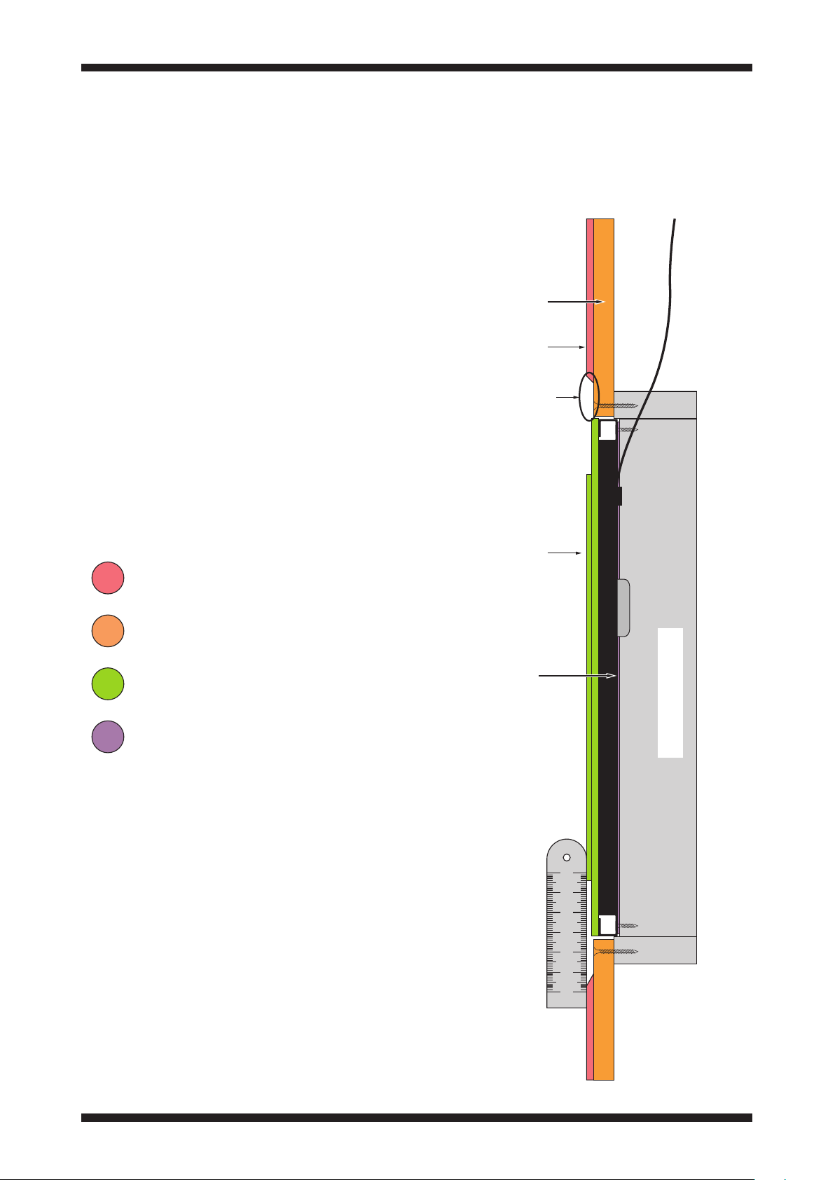
Alignment required for plastering
The diagram shows the same ‘Retrofit’
installation as page 23, but to achieve
a flush finish the raised section of the
speaker is aligned with the surrounding
plaster.
plasterboard
To achieve this alignment, shims of the
correct size will be required.
Approximately 25mm (
1
/2”) width of
plaster should be removed around the
opening before fitting the speaker, to
make room for the application of joint
tape.
Plaster
Plasterboard
Speaker panel
Shim
existing
plaster
approximately
25mm width
of plaster is
removed around
the speaker
raised section
of speaker
panel
shim
BackboxCV345
Shim sizes
Shims will be required to space the
speaker out to meet the face of the
plastered wall.
To determine the exact size of shim
required, measure the thickness of
the wall including plaster and subtract
13.5mm (
17
/32”).
For example, if the wall thickness
measures 14.5mm (
9
/16”), the shim
thickness required will be 1mm.
The shims are fixed to the mounting face
of the speaker (see page 19).
Click to return to the contents section on page 2
Page 26
25
Alignment and preparation
For new stud walls / ceilings using Fixing Blocks
Alignment required for plastering
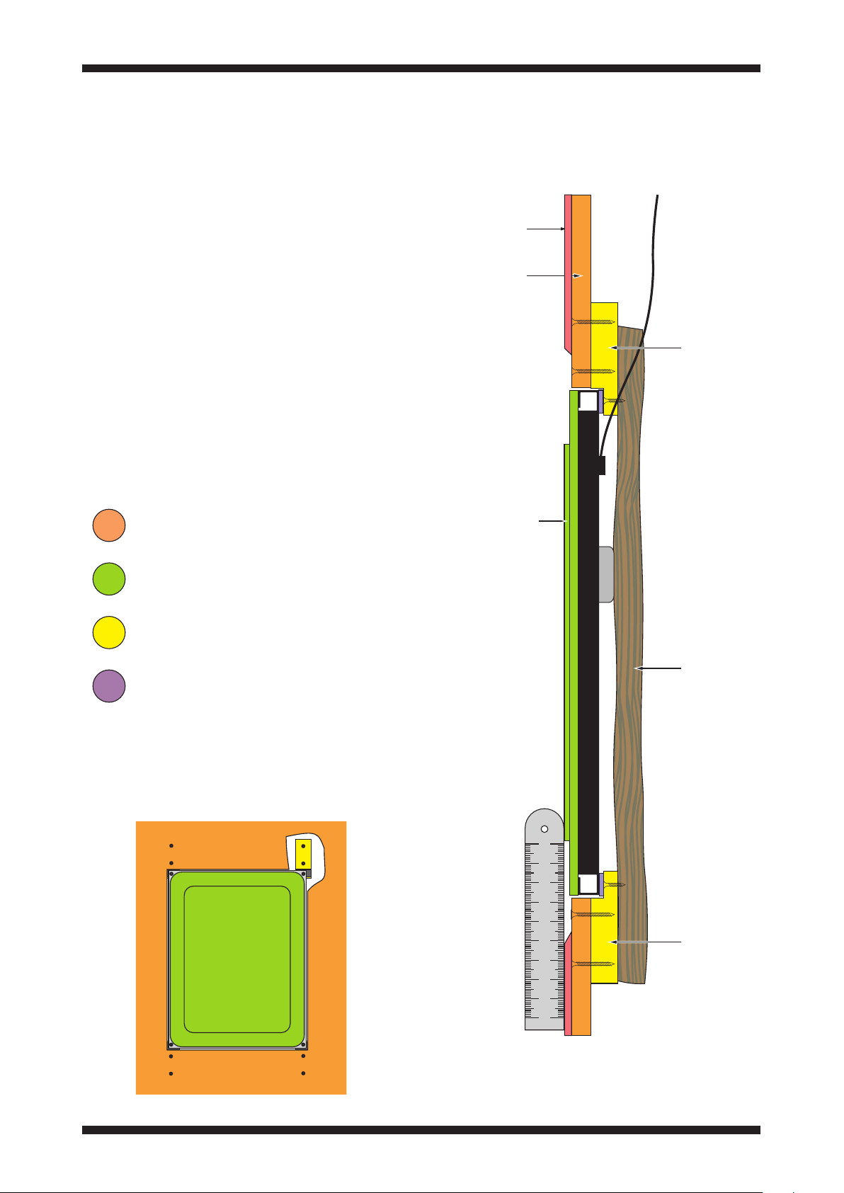
Fixing blocks are used in installations
where BackboxCV cannot be used.
Plaster
The diagram shows an Edge loudspeaker
fitted in a new stud wall with Fixing
blocks.
When correctly installed, the raised
surface of the speaker panel will align
with the surface of the surrounding
plaster.
A shim may be necessary as shown to
achieve the correct alignment.
The cavity behind the speaker should be
packed with acoustic wadding to reduce
back radiated sound.
Plasterboard
Speaker panel
Fixing block
12.5mm (1/2”)
plasterboard
Fixing block
raised face of
speaker panel
Shim
The view below shows a speaker fitted
with Fixing blocks. The plasterboard is
cut away from the top right Fixing Block
to show correct alignment of the block
behind the plasterboard.
Acoustic wadding
Fixing block
Click to return to the contents section on page 2
Page 27
26
Testing
Testing the speaker
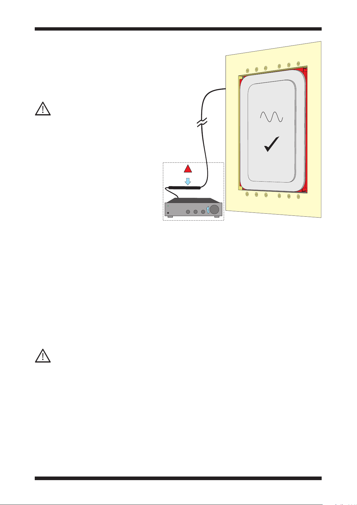
At this stage the speaker must be tested.
If any problems are found the speaker
can be easily removed before plastering.
CAUTION:
Do not use use a battery or DC
voltage supply to check continuity or
phase check as there is no forward or
backward movement of the panel.
DC voltage can damage the speaker.
100Hz - 1kHz
!
APUi
Resistance test
Using a multimeter and without the APU
protection device connected, check the
nominal impedance (DC resistance) of
the speaker at the amplifier end of the
speaker cable.
Allowing for approx. +10% for cable
resistance, the measured impedance
should coincide with the values on the
respective loudspeaker datasheets.
If it measures significantly differently,
check for breaks or shorts in the cable.
CAUTION:
Connect the APU protection device
Once the resistance test is successfully
completed, connect the APU protection
unit at the amplifier end of the cable
before proceeding with further tests.
Sweep test
Amina recommends a tone sweep
be used at a moderate volume level
(0.5 Vrms). Such a test will quickly
highlight any buzzes or rattles that
could be caused by loose screws,
cables touching the speaker or
loose elements/studs within the
wall/ceiling itself.
NOTE: A tone sweep test must be
run initially as it is the most reliable
test for buzz and rattle. Music tests
are useful, optional tests for final
confirmation.
Music test
Play music to check for buzzes and
rattles during transient peaks: if
these are apparent, check the above
points again. The overall speaker
performance must be clean and
distortion free.
Problems during test
If the tests reveal any rattles or
buzzes, refer to the next section for
help to find the cause.
Click to return to the contents section on page 2
Page 28

27
Testing
Problems during test
if you encounter any rattling or buzzing
problems during test, check the following
section to resolve these issues.
CAUTION:
Never proceed with plastering until the
speaker has passed both sweep and
music tests.
The following list may help you trace
the cause of any rattling or buzzing
problems.
Insecure drywall
If the drywall is not securely fastened to
the joists, this could create a buzz or a
rattle. Apply more screws to secure the
drywall if necessary - particularly around
the speaker location.
Metal studs
If metal studs are used, ensure all
crossover points within the studs are
secured together. This can be achieved
by applying drywall screws through
the wall surface and through the metal
crossover points.
If they are not secure this may well lead
to audible vibrations and rattles.
Cable buzzing
Ensure that the speaker cable is not
touching any part of the speaker as this
can lead to buzzes and rattles. To avoid
this it is advised to lay the cable behind
mineral wool, recycled cotton or other
wadding.
Lighting fixtures
Ensure lighting fixtures, especiall y those
closer to the loudspeakers are of a solid
construction and are firmly fixed in place.
Click to return to the contents section on page 2
Page 29
28
Finishing
Filling the perimeter
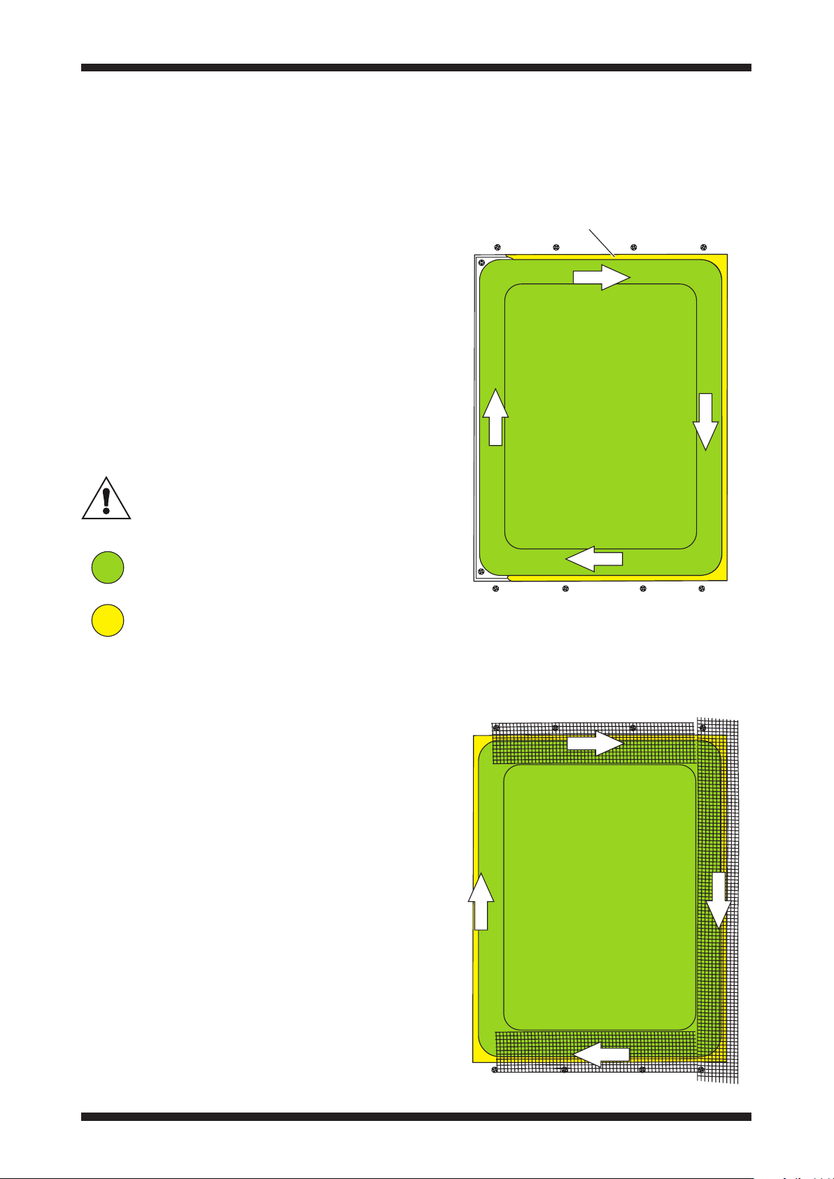
Once the speaker is fixed into place, the
gap must be filled with plaster to bond
the edge of the panel to the edge of the
plasterboard.
Wipe away filler from the panel surface
(both the outer perimeter and raised
sections).
Use a low shrinkage repair plaster such
as British Gypsum Gyproc-Joint-Filler or
other similar joint compound.
Allow this to dry fully before
continuing with the installation.
Speaker panel
fill the gap between the
speaker panel and the wall
Plaster to fill the edge
Taping the joints
Using 50mm (2”) plaster jointing scrim
tape, tape across the perimeter of the
speaker frame as shown.
Prior to taping, wipe the surface clean
with a damp cloth and allow to dry.
Paper tape can also be used. Use usual
methods to apply paper tape (wetted
if necessary and set into wet joint
compound).
NOTE: Place the joint scrim as close to
the raised front surface as possible.
Click to return to the contents section on page 2
Page 30
29
Finishing
Feathering the panel edge
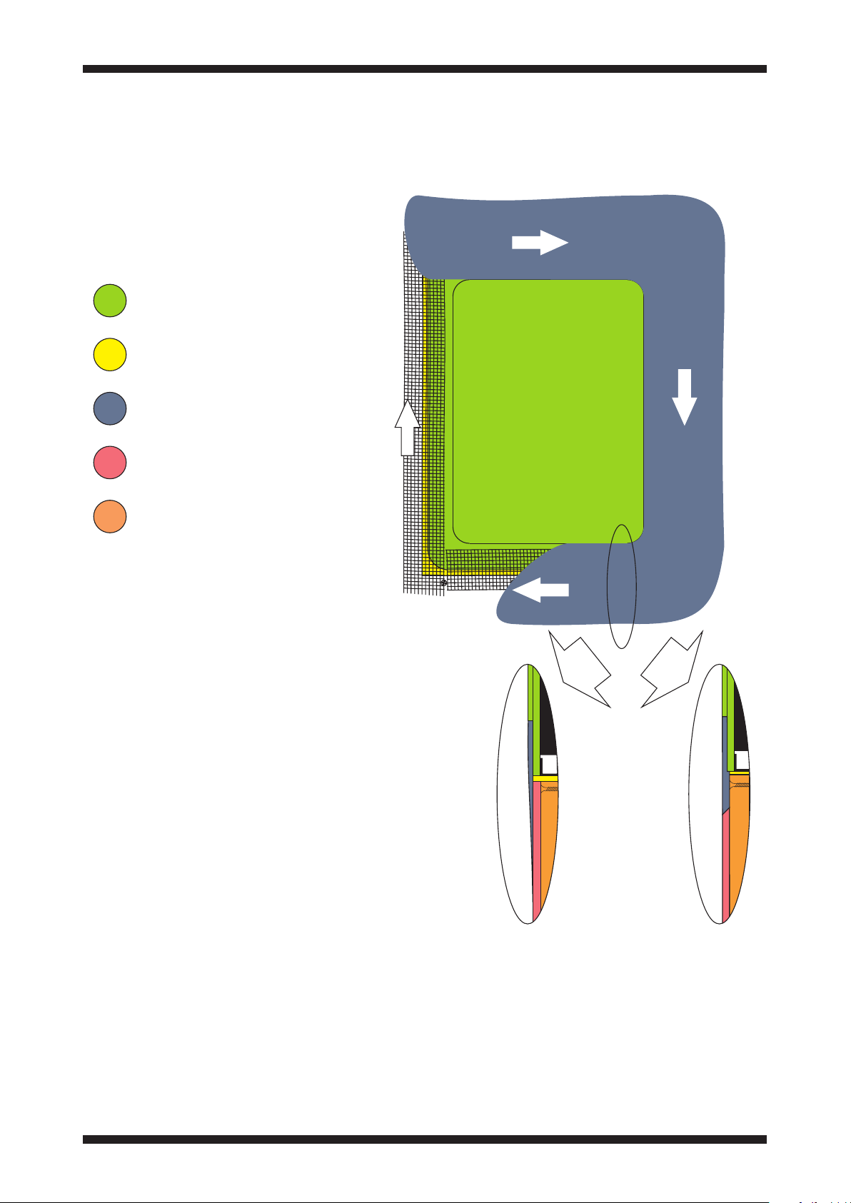
Feather in plaster to the edge of the
raised section.
Speaker panel
Plaster to fill the edge
Feathered surface filler skim
Original plaster
Plasterboard
Cutaway view
This cutaway view shows a section
through the finished skim in the area
shown.
Click to return to the contents section on page 2
Flush centreFlush surround
Page 31
30
Finishing
Fine surface finishing (optional)
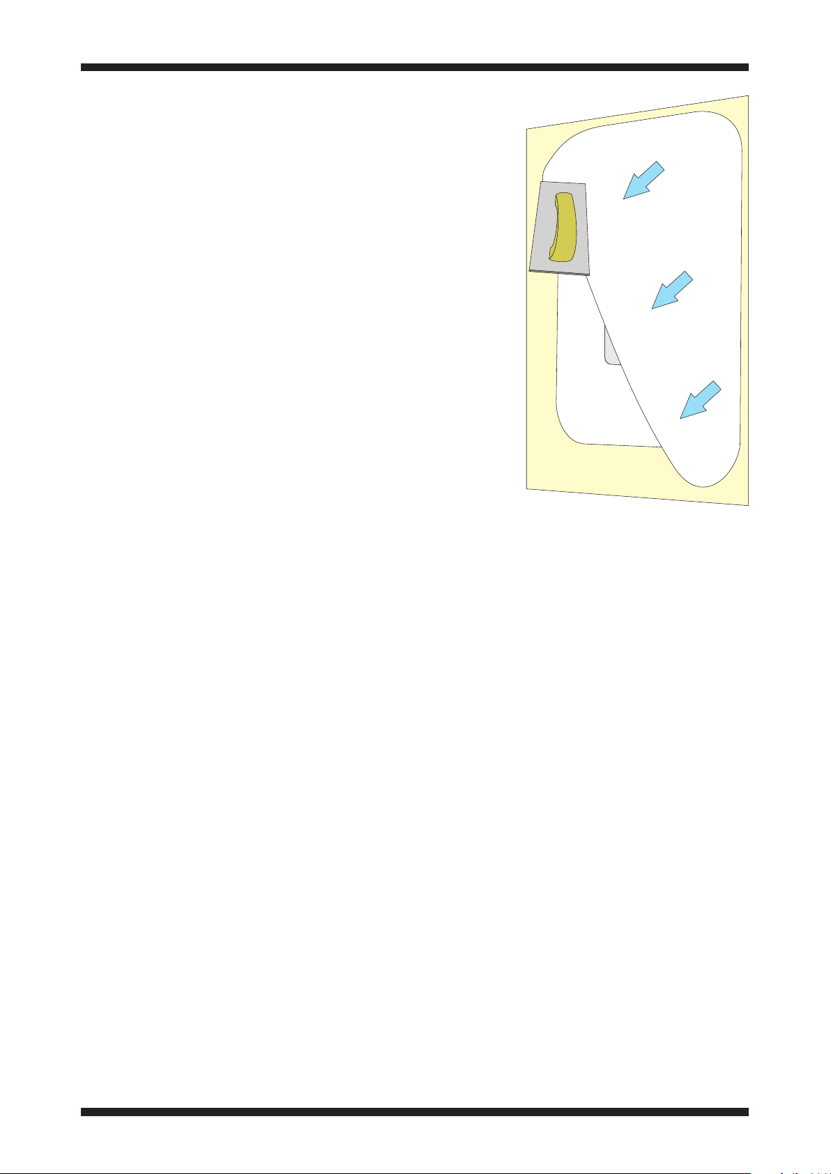
To finish the installation, a very light coat
of fine surface filler, less than 0.5mm
(1/64”) may be used over the entire front
surface of the speaker to blend the panel
appearance with the surrounding plaster.
Amina recommend using Toupret® ready
mixed fine surface filler.
Filler can be sanded/wiped smooth to
achieve the correct texture. Care should
be taken not to sand any exposed paper
panel surface.
Click to return to the contents section on page 2
Page 32

31
Decorating
Allow your plasterwork to dry completely.
Test the speaker again. You can then
paint the surface or hang wallpaper in
the usual manner.
Amina Invisible speakers have been
optimised for three coats of emulsion
once plastered. Additional coats
will cause very small reductions in
the maximum sound pressure levels
achievable.
Completed and fully dried plaster
surfaces should be finished with
permeable coatings / materials to allow
moisture in that coating or the adhesives
used to apply those materials, to dry into
the environment quickly.
Oil based coatings and other nonpermeable surfaces will trap moisture
in the plaster surface for many days
and even weeks. This has the potential
to work its way back to the Amina
loudspeakers exposing them to an
unacceptably damp environment for an
extended period.
The use of impermeable coatings and
materials should be considered carefully
and with caution. Bare plaster surfaces
must be pre-treated with a primer /
sealing coat that is permeable during its
drying process. The entire surface must
then be fully dry (this may take some
weeks) before applying the impermeable
coating or material.
Maintenance and cleaning
Once your speaker is plastered into your
wall or ceiling, it requires no physical
maintenance. Your wall or ceiling can be
cleaned with products appropriate to
the finish finally applied to the plaster
surface.
Re-decoration
The wall or ceiling can be painted or
redecorated any number of times, but
please be aware that sound output will
reduce very slightly with each coat.
Extreme care should be taken when
removing wallpaper type coverings to
ensure the panel surface is not damaged.
If damage to the plaster work occurs,
use repair plaster to restore the plaster
surface prior to re-decorating. Amina
Technologies Ltd recommends British
Gypsum Gyproc-Joint-Filler as a repair
plaster.
Avoid pushing the wall or ceiling surface
immediately in front of the speaker.
Excessive excursion, whilst unlikely to
damage the speaker, can cause the
plaster to crack around its perimeter and
can ultimately damage the loudspeaker.
Ensure the building is environmentally
sealed, de-humidified (to a max of RH
50%) and at a standing temperature of
at least 16°C (61°F).
Click to return to the contents section on page 2
Page 33
32
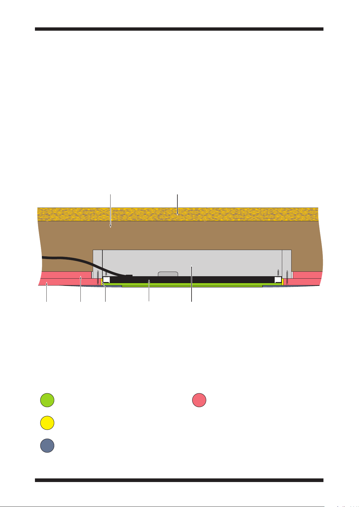
Fire resisting installation
The Amina Edge 7 loudspeaker is
certified for installation in areas where
fire compliance is required to standard
BS476 Pt 21: Timber floors.
This will generally be in multi-level
buildings such as offices, apartments and
flats where the ceiling and any fittings
in the ceiling must maintain a 60 minute
barrier to fire.`
The fire rated ceiling should be built in
accordance with the British Gypsum
white book specification for 60 minute
ceilings.
Rafter Chipboard floor
To meet the requirements of this
standard, and to ensure a full 60
minute rating, the Edge loudspeaker
and Backbox must only be installed in
accordance with the instructions in this
section.
The cross-section views that follow
illustrate the completed installation of
an Edge loudspeaker in a ceiling. Study
these before commencing installation.
Outer
Fire-retardent
Inner
plasterboard layers
Loudspeaker panel
Gyproc joint filler
Plaster
BackboxCV345
Gyproc Joint Filler
Click to return to the contents section on page 2
Edge loudspeaker
Fire-retardent plasterboard
Page 34
33
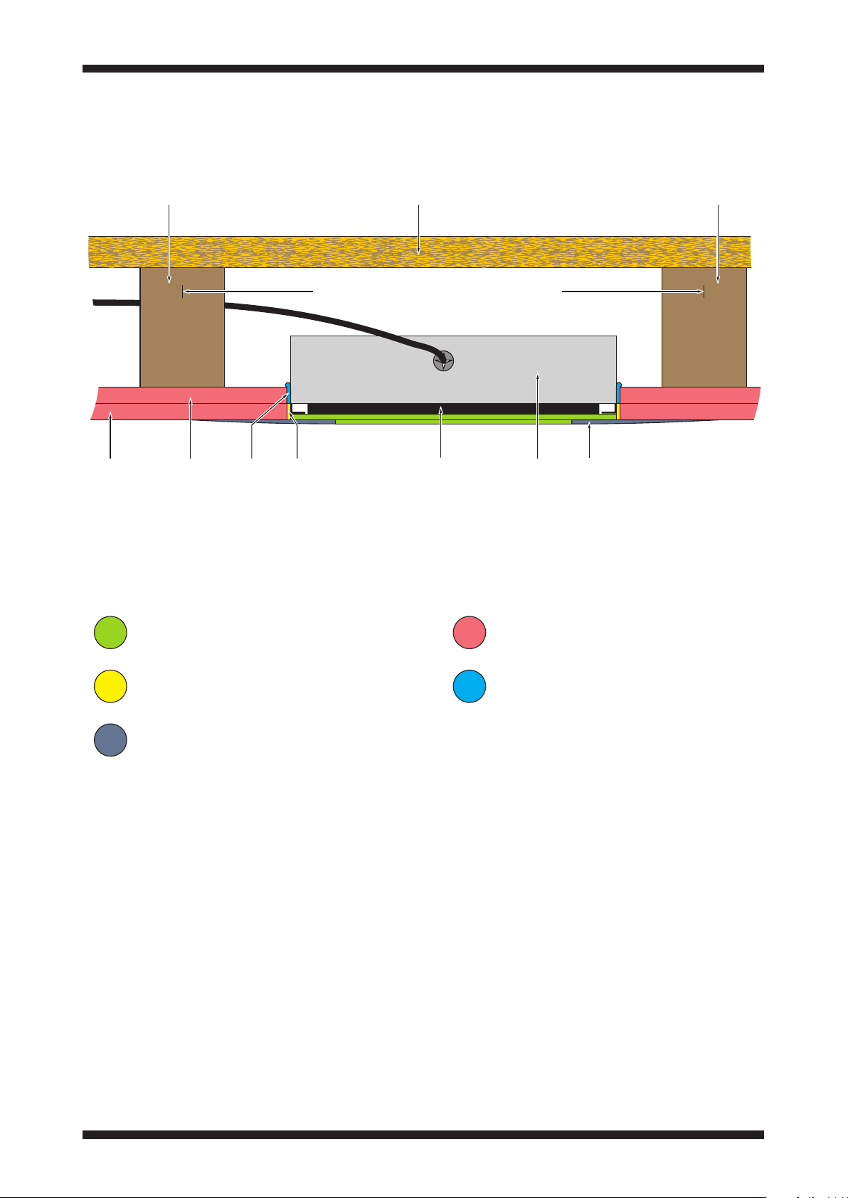
Fire resisting installation
Rafter Chipboard floor Rafter
Max 600mm (23
9
/16”) centres
plasterboard layers
Inner
mastik
Gyproc
Astroflame
joint filler
Outer
Fire-retardent
Loudspeaker panel
Gyproc Joint Filler
Plaster
Pre-installation checks
Materials must be the correct grade for
fire-retardent installation.
Plasterboard must be the correct
60 minute grade of fire-retardent
plasterboard. This is usually coloured
pink.
The plasterboard must be 12.5mm (
thick to achieve the correct alignment of
the loudspeaker with the ceiling.
Spacers must not be used in fireretardent installations.
1
/2”)
Edge
loudspeaker
BackboxCV345
Fire-retardent plasterboard
Astroflame Intumescent Mastik
Plan the locations for the Edge
loudspeakers. Ensure there is clearance
around each loudspeaker position from
rafters and any other fittings in the
ceiling.
CAUTION: Under no circumstances
cut the rafters or fix the BackboxCV to
the rafters in any way. The BackboxCV
must be fixed only to the outer layer of
plasterboard.
Plaster skim
To preserve the fire barrier, filler and
sealant must only be the types specified.
Click to return to the contents section on page 2
Page 35
34
Fire resisting installation
Installation
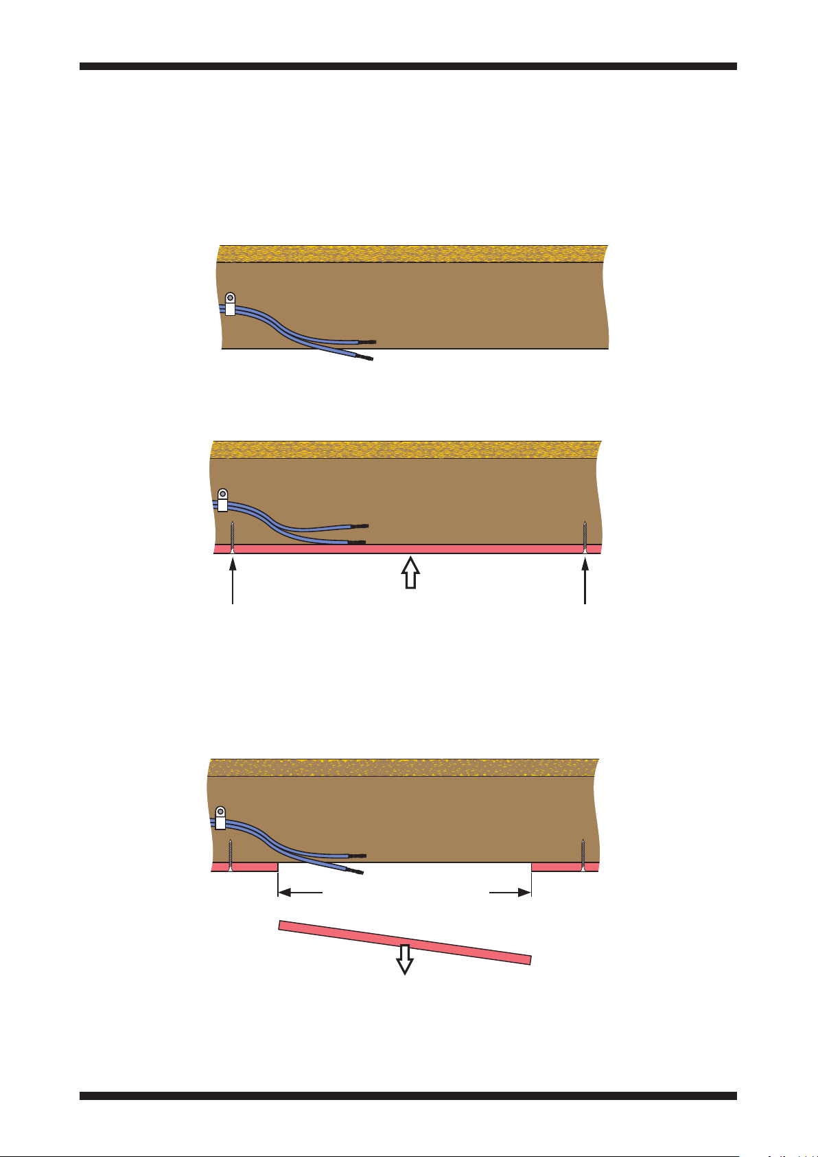
1. Route a cable from the location of the amplifier through the ceiling space to the
location of each loudspeaker. Ensure that there is enough free cable length available
to allow each speaker to be connected.
2. Fix the first layer of fire-retardent plasterboard to the rafters.
3. Using a sharp knife or pad saw, cut an aperature in the plasterboard at each
speaker location. The BackboxCV will pass through these holes so cut them to
502mm x 350mm (19
To maintain a fire barrier the BackboxCV must fit into the opening with minimal
clearance.
3
/4” x 13 3/4”)
502mm x 350mm
(19 3/4” x 13 3/4”)
Click to return to the contents section on page 2
Page 36
35
Fire resisting installation
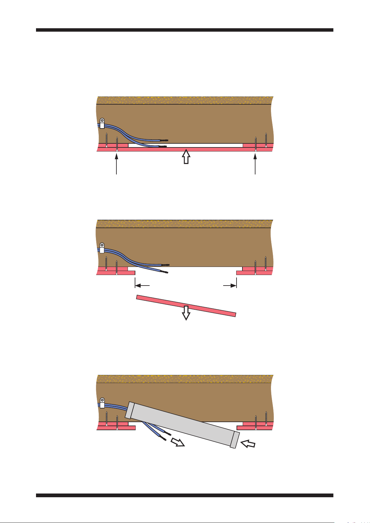
4. Fix the outer layer of plasterboard over the first layer.
7
5. Cut a smaller 452 x 347mm (17
plasterboard, centred on the aperatures in the inner plasterboard layer.
/8” x 13 3/4”) aperature in the outer layer of
452 x 347mm
(17 7/8” x 13 3/4”)
6. Feed the cable through the grommet in the BackboxCV and lift the BackboxCV into
position through the opening. Drop the BackboxCV into place to rest on the outer
layer of plasterboard.
Click to return to the contents section on page 2
Page 37
36
Fire resisting installation
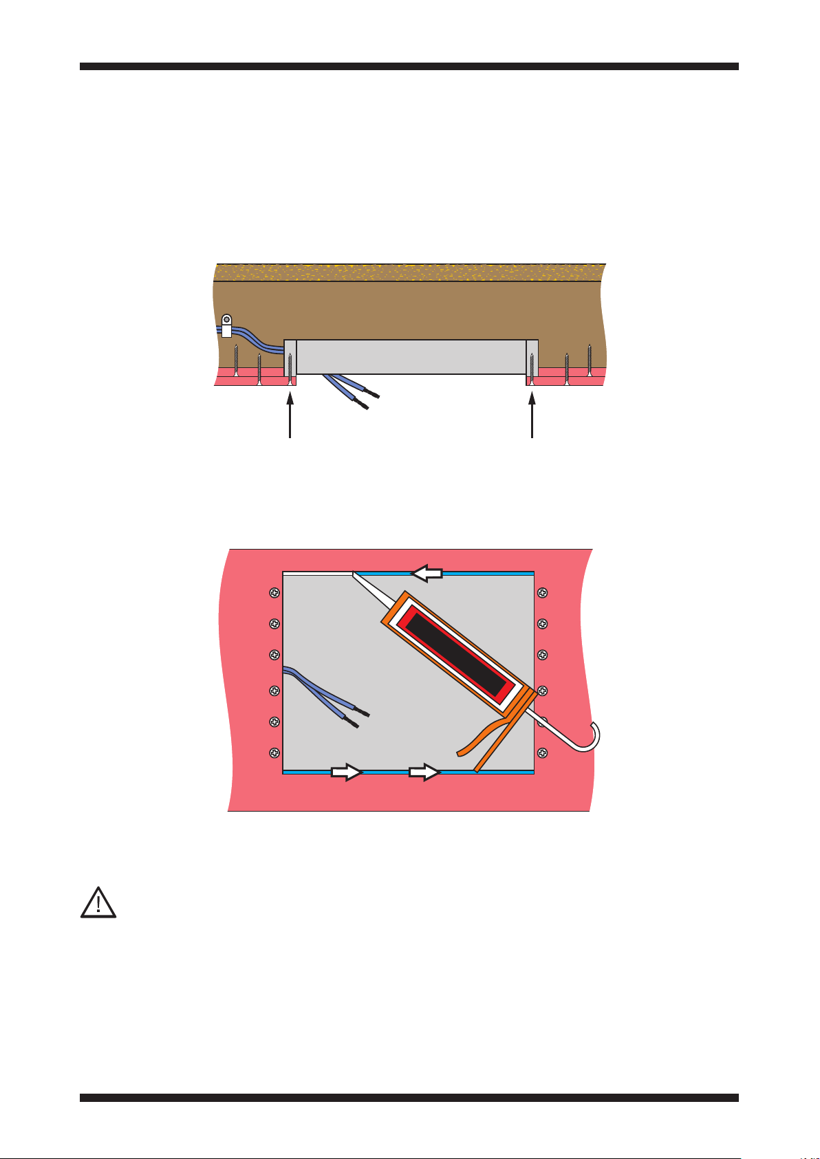
7. Fix the BackboxCV into position with four to six screws fitted through the end
flanges.
1
NOTE: No shims are necessary when fitting an Edge speaker into 12.5mm (
plasterboard in this way.
/2”)
x4/x6
8. Thoroughly seal any gaps between the long edges of the BackboxCV and the inner
layer of plasterboard with Astroflame Intumescent Mastik.
ASTROFLAME
x4/x6
The Astroflame Intumescent Mastik must only be applied to the two long edges
of the BackboxCV as shown, never to the short edges.
Click to return to the contents section on page 2
Page 38
37
Fire resisting installation
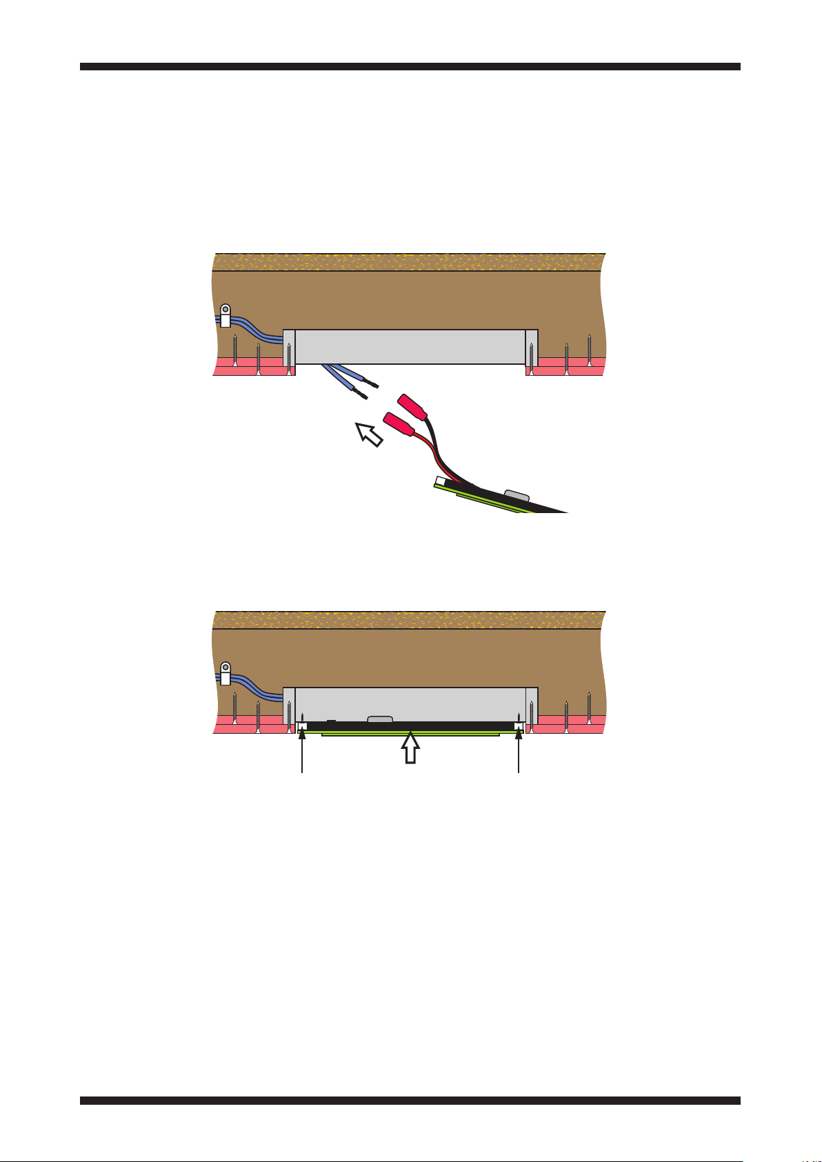
9. Connect the speaker cable to the butt splice terminals on the loudspeaker wiring.
Ensure that the polarity of the connections is correct, then crimp the wires to
complete the joints.
10. Screw the loudspeaker into place in the BackboxCV.
11. Follow the instructions on page 26 to fully test the loudspeaker. Impedance tests,
Sweep tests and Music tests should all be completed before filling the panel edge.
Click to return to the contents section on page 2
Page 39
38
Fire resisting installation
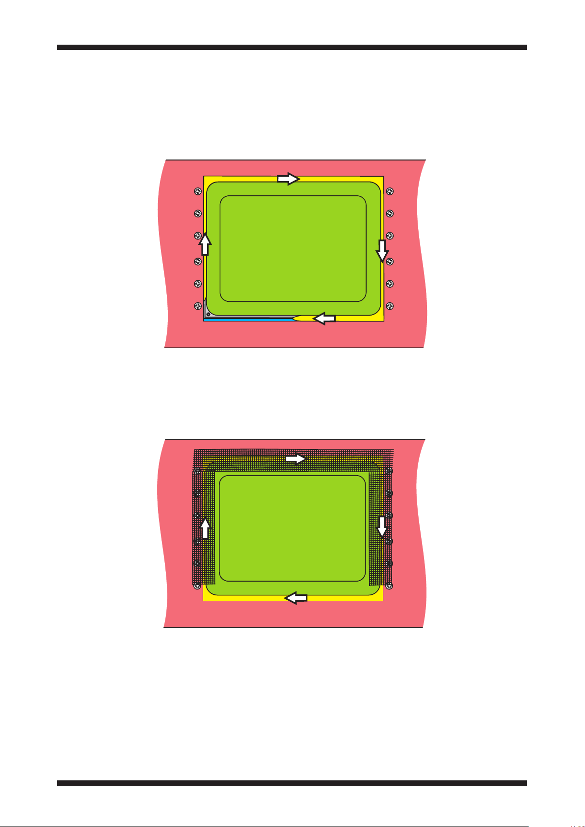
12. Working from the face of the loudspeaker, fill the gap between the loudspeaker
panel and plasterboard with Gyproc Joint Filler. Allow the filler to dry thoroughly.
13. Using 50mm (2”) plaster jointing scrim tape, tape across the perimeter of the
speaker frame as shown.
Click to return to the contents section on page 2
Page 40
39
Fire resisting installation
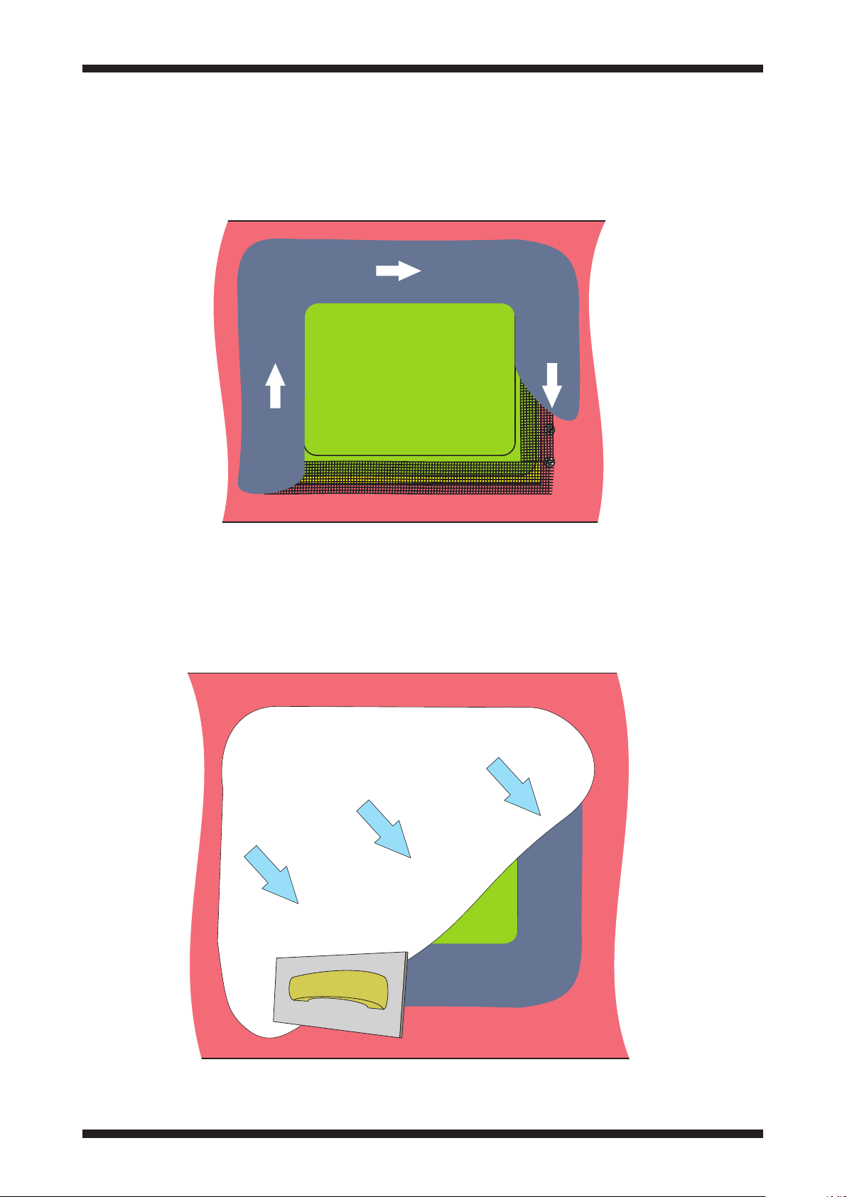
14. Feather in plaster to the edge of the raised section to complete the installation. Use
British Gypsum Gyproc joint filler for the first coats, finish with a fine surface filler.
15. To finish the installation, a very light coat of fine surface filler, less than 0.5mm
(1/64”) may be used over the entire front surface of the speaker to blend the panel
appearance with the surrounding plaster. Amina recommend using Toupret® ready
mixed fine surface filler. Filler can be sanded/wiped smooth to achieve the correct
texture. Care should be taken not to sand any exposed paper panel surface.
16. When the plaster has fully dried, re-test the loudspeaker as before.
Click to return to the contents section on page 2
Page 41

40
Fire resisting installation
Other fire resisting installation methods
Other methods of creating a fire resisting installation are possible for all Amina
loudspeakers.
These include pre-building an appropriate plasterboard lined compartment at the
rear of the loudspeaker/BackboxCV or using commercially available fire hood type
products.
Click to return to the contents section on page 2
Page 42
41
Accessories
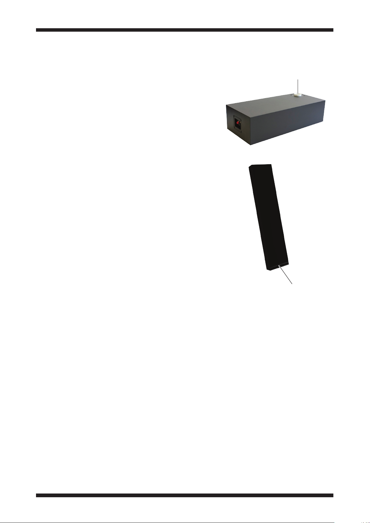
Subwoofers
ALF80
150W passive subwoofer with unique
adjustable port design allowing the
product to be installed within joinery,
behind kick boards or within ceilings or
other voids. Highly discrete, powerful and
deep bass response is achieved with only
a small opening for the port required
within the room.
ALF120
Amina have developed an astonishing
subwoofer technology dubbed
‘distributed transmission line’ (DTL),
which allows the design of a subwoofer
thin enough to be built into a stud wall,
venting through a simple slot in the
skirting board, to create an impressively
low 27Hz audio output at 111dB loudness
using only 50W of power.
Port opening
ALF80
ALF120
Port opening
Click to return to the contents section on page 2
Page 43

42
Troubleshooting
Thorough testing of the loudspeakers
should be carried out both prior to and
after plastering to avoid time consuming
repairs or modifications at a later stage.
Should you encounter any problems at
either of the test stages the following
guide is designed to help determine
possible problem areas.
CAUTION:
Do not use use a battery or DC voltage
supply to check continuity or phase
check as there is no forward or backward
movement of the panel.
DC voltage can damage the speaker.
Advice for testing
• When testing always use a basic
sound system (amp, source,
loudspeakers) to eliminate the
possibility of faults with other, more
sophisticated components, such as
control systems.
• Test at low and medium volumes and
be careful not to exceed the specific
speaker model’s recommended power.
Using tone sweeps or music as test
material, listen for distortion, buzzing
or rattles at appropriate levels. Using
test discs or music, confirm that all
channels are in-phase.
• Ideally professional test equipment
should be used to record a
full frequency response of the
loudspeaker before and after
plastering.
No or low sound output
• Check continuity of all cables.
• Check that all cables and connections
are made correctly, are intact and
that all channels have the correct
polarity (+ to + and - to - from amp to
speaker).
• Using an impedance meter, check the
nominal impedance of the speaker
(APU must not be connected) both
at the loudspeaker and the amp end
of the cable. Do these measurements
match each other? (Allowing for the
small impedance increase of less than
1 ohm along the wire length) Do they
match the stated nominal impedance
on the loudspeakers specification
label? If the nominal impedance,
measured at the loudspeaker is
dramatically different to the product’s
stated impedance, a speaker driver
may be open circuited or short
circuited. If so, the product may need
to be returned to Amina for repair or
replacement.
• If the nominal impedance at the end
of the cable is very different to the
impedance at the speaker, check your
cables. Cuts or nicks in the cable
along its length can dramatically
increase impedance or create a short
circuit, dramatically lowering the
impedance.
Click to return to the contents section on page 2
Page 44

43
Troubleshooting
Distortion, buzzing or rattles at modest volumes
• Try to identify the location of the buzz
or rattle. It may be caused by a loose
screw or other mechanical object.
Check the wall or ceiling and speaker
assembly and ensure screws and
fixings are tight.
• If the rattle persists, remove the
speaker from the wall and check your
wiring to the product. Ensure that
wires, with the speaker in the final
location, are not resting against the
speaker or backbox (if used), causing
vibrations.
• With no audio signal applied, lightly
push the speaker face in and out at
its centre. Listen carefully for rubbing
on the driver, which may sound like
scratching. This may indicate the
speaker has been over driven and
subsequently damaged. The speaker
will need to be sent to Amina for
repair or replacement.
Very low output after speaker passes electrical tests
• With no audio signal applied, lightly
push the panel in and out at its center.
Listen carefully for rubbing voice
coils on the driver, which may sound
like scratching. This may indicate the
speaker has been over driven and
subsequently damaged. The speaker
will need to be sent to Amina for
repair.
Distortion at higher volume levels
• Diffuse source panel loudspeakers
of this type have an extremely fast
response, articulating the signal from
your audio system very accurately.
Take your system back to the bare
minimum (amplifier, source and
loudspeakers) to eliminate distortions
introduced by other components.
• When using your amplifier at
maximum power levels, or if the input
of your amplifier is being overloaded,
the signal level may be ‘clipping’.
With some conventional loudspeakers
this may not be evident, but with
a diffuse source panel speaker you
are much more likely to hear the
distortion. Consider adjusting or
upgrading your system.
NOTE: Excessive pressure on the front of the speaker panel may cause cracking in
the plaster which may need to be filled.
Click to return to the contents section on page 2
Page 45

44
Specifications
Amina Edge series - Plaster up to products
Model number Edge5i Edge7i
Dimensions
Weight
Nominal impedance
Frequency response
Sensitivity
(@1m/2.83Vrms)
In-line protection unit
(single channel)
In-line protection unit
(multi-channel)
Fixing requirement
Power handling
(continuous)
Power handling
(peak)
Operating temperature
range
Manufacturer warranty
450mm x 345mm x 38mm
(173/4” x 135/8” x 11/2”)
1.30kg (2lbs 10oz) 1.80kg (3lbs 15oz)
4Ω 4Ω
55Hz to 26kHz 50Hz to 27kHz
90dB 90dB
APUi50C_2 APUi70C_2
APU-RS8iC / APU-RS16iC
Amina BackboxCV345 / Basic fixing kit
50W 75W
100W 150W
16°C - 40°C (61°F - 104°F)
10 years (residential systems), 5 years (commercial systems)
450mm x 345mm x 33mm
(173/4” x 135/8” x 15/16”)
Model number Edge3
Dimensions
Weight
Nominal impedance
Frequency response
Sensitivity
(@1m/2.83Vrms)
In-line protection unit
(single channel)
In-line protection unit
(multi-channel)
Fixing requirement
Power handling
(continuous)
Power handling
(peak)
Operating temperature
range
Manufacturer warranty
400mm x 300mm x 31mm
(153/4” x 117/8” x 11/4”)
0.97kg (2lbs 2oz)
8 ohm
90Hz-24kHz
86dB
APUi30C
APU-RS8iC / APU-RS16iC
Amina BackboxCV300 / Basic fixing kit
30W
60W
16°C - 40°C (61°F - 104°F)
10 years (residential systems), 5 years
(commercial systems)
Click to return to the contents section on page 2
Page 46

45
Warranty information
Limited Warranty:
Amina loudspeakers are designed to operate reliabl y for many years. Correctly
installed in accordance with these instructions, Amina warranties the loudspeakers
against defective materials and manufacturing workmanship for a period of ten years
in residential and five years in commercial applications.
At the end of the speaker’s useful life and in compliance with the European directive
on waste electrical and electronic equipment (WEEE), this product is to be returned
to your supplier, or directly to Amina for recycling. If you have any questions please
contact Amina Technologies Ltd.
* Please refer to our full warranty statement for details, available on our website, or
alternatively contact us via email.
Important Note: This product has not been tested to European Construction Products
Regulations EN 54-24 and therefore must not be used in voice evacuation systems
located within the European Union.
Copyright information
This document is Copyright of Amina Technologies Ltd, 2019
Gyproc-Joint-Filler is a registered trademark of British Gypsum Ltd
Amina is a registered trademark of Amina Technologies Ltd
Amina Edge is a registered trademark of Amina Technologies Ltd
Amina Sound is a registered trademark of Amina Technologies Ltd
Astroflame is a registered trademark of Astroflame (Fireseals) Ltd.
Toupret is a registered trademark of Toupret S.A., France.
Contact information
Amina Technologies Ltd
Cirrus House, Glebe Road, Huntingdon
Cambridge, PE29 7DL, UK
T: +44 (0)1480 354390
E: [email protected] - enquiries
E: [email protected] - expert advice
E: [email protected] - sales team
W: www.aminasound.com
Registered in the UK, company no: 3656822
Click to return to the contents section on page 2
Page 47

®
THE INVISIBLE SPEAKER CO.
Audio for very smart homes
®
Amina Technologies Ltd
Cirrus House, Glebe Road
Huntingdon, Cambs, PE29 7DL England
T: +44 (0)1480 354390
W: www.aminasound.com / E: [email protected]
Copyright 2019
Edge with BackboxCV V3.5
 Loading...