

Page 1

XG Programmable Power Supplies:
Application Note
Rack Mount Kit Options and
Installation Instructions
This Application Note provides information on the options available for rack mounting the XG
series and provides installation instructions for the rack mount kit options. The complete set of
instructions for installing the XG power supplies are provided in the XG 850 Watt Series
Programmable DC Power Supply Operating Manual (Part number: M370078-01 for firmware
v1.09 and below, and M370186-01 for firmware v1.11 and higher). See the Installation chapter
for additional information.
Rack Mount Kit Options
Table 1 describes the options available for rack mounting the XG and provides the part numbers
for each option.
Table 1
Unit Option A: Rack Mount with Rails Option B: Rack Mount with Slides
XG 850 Watt Single RM-S-XG1 and RM-XG1 RM-S-XG1. See Table 2 on page 7.
XG 850 Watt Dual RM-D-XG1 and RM-XG1 RM-D-XG1. See Table 2 on page 7.
Rack Mount Options
XG 850 Watt
M370078-05 Rev C
XG 850 Watt Single and Dual
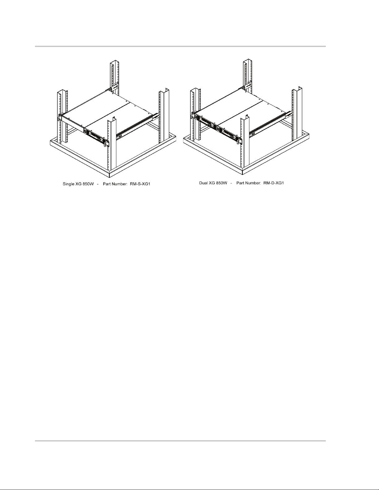
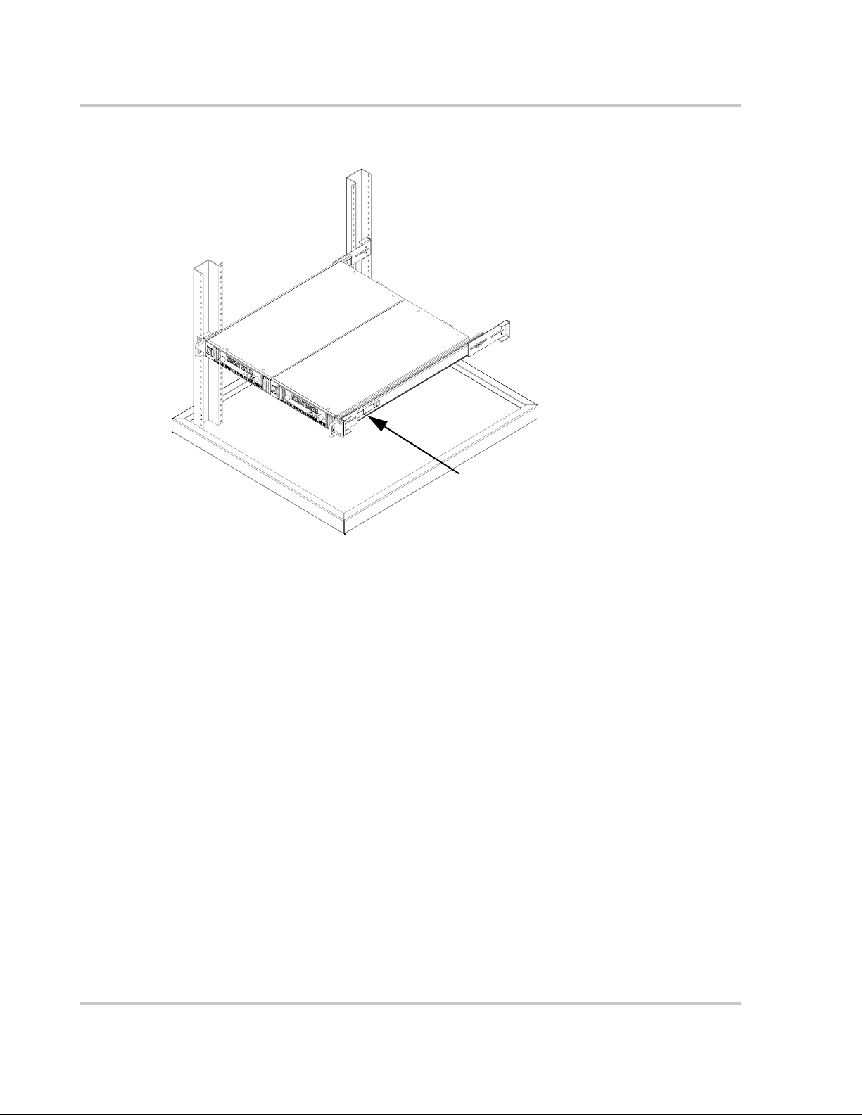
Figure 1 shows the rack mount kit options for installing the XG 850 Watt into a rack.
Page 2
XG 850 Watt Rack Mount Kit Options
Figure 1
XG 850 Watt Single and Dual Rack Mount Kit Options
2 M370078-05
Page 3
XG 850 Watt Rack Mount Kit Options
Location Requirements
Install the XG in a location that meets the following requirements:
Condition Description
Clean The XG should not be exposed to metal filings or any other form of conductive contamination.
Cool The ambient air temperature should be between 0 °C–50 °C (32 °F–122 °F) for best performance.
Ventilated Whether operating the power supply in a rack or on a bench, allow air to reach the ventilation
inlets on the front and rear of the unit for cooling. The direction of airflow is from the front to the
back of the unit. Ventilation space at the top, bottom or sides of the power supply is not required
WARNING: Shock hazard
Ensure that any mounting screws do not penetrate more than 1/8 in. (3.0 mm) into the bottom
and/or the back of the unit.
M370078-05 3
Page 4

XG 850 Watt Rack Mount Kit Options
Mounting Option A: 1U Rails
1U rails are to support the XG rack mount packages. The rail is a flanged rail type and only
available for a rack depth of 25 inches.
The part number to order this option is RM-XG1.
Tools and Materials Required
To mount and connect the XG, you will need the following tools and materials:
• Screwdriver (Phillips head, #2)
• Standard carpenter’s level
• Eight #10-24 × ¼" (30 mm) Phillips head screws.
Installation Procedures
To install the power supply in an equipment rack:
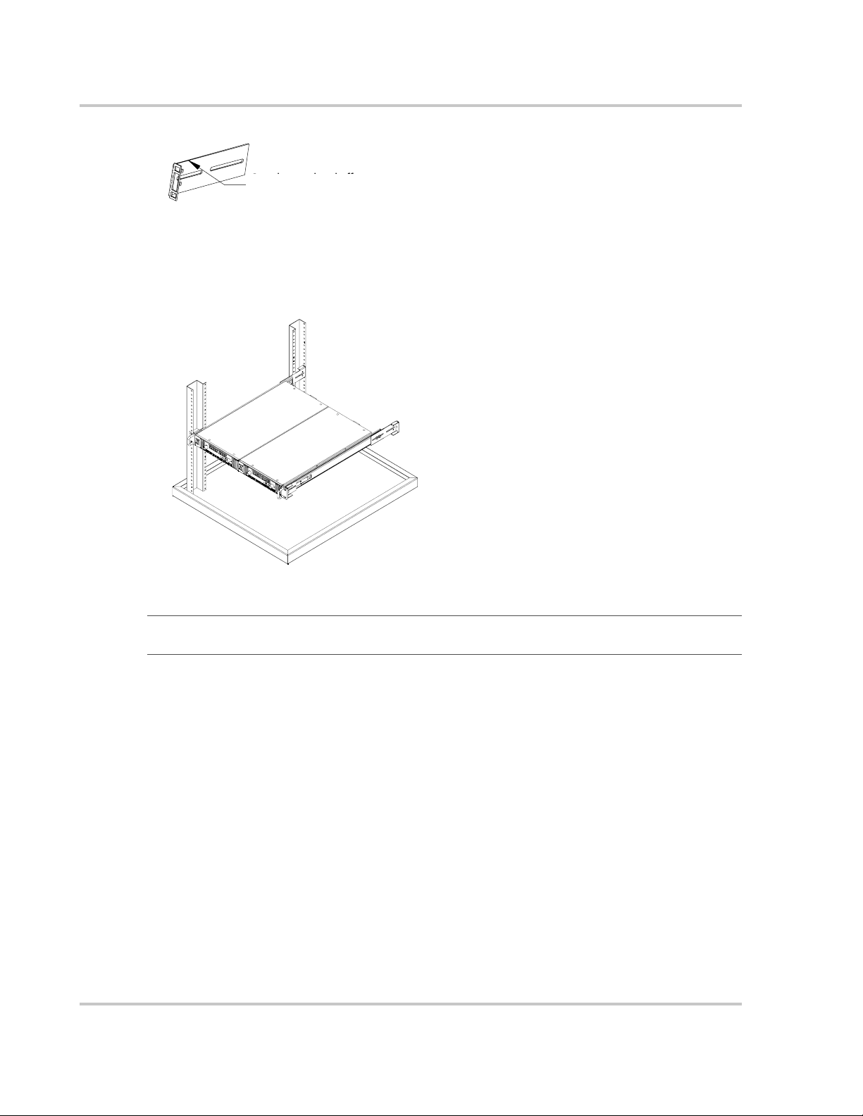
1. Ensure that your rack resembles the rack shown in Figure 2, and has inner holes within the
specified dimensions.
2. Find the 1U space in which you wish to install your power supply in the specific rack.
3. Place the lower plain flange of the RM-XG1 rail at the lowest point of the 1U space. If it is
placed correctly, a hole on the inner flange of the vertical rack will line up to the oval
mounting slot in the rail.
4. Using the carpenter’s level for accuracy, install the rail using two #10-24 screws.
5. Tighten the screws to a torque of 20.5 to 22.5 in-lbs.
6. Repeat on the opposite side, using the level to ensure both rails align.
7. Slide the XG assembly onto the rails, and against the front rails of the rack.
8. If there are four front mounting locations available, then install four #10-24 screws. Tighten
the screws to a torque of 20.5 to 22.5 in-lbs. If there is only one hole available on either side,
then the RM-XG1 rails are not installed correctly.
4 M370078-05
Page 5

18.6" ±0.5"
XG 850 Watt Rack Mount Kit Options
Figure 2
RM-XG1 Rack Rails
M370078-05 5
Page 6

XG 850 Watt Rack Mount Kit Options
Mounting Option B: Manufactured Slides from Jonathan®
Engineered Solutions
Jonathan Engineered Solutions offers a wide variety of manufactured slides to allow the easy
installation and removal of the XG assemblies into all rack sizes. Follow these steps to find the
Jonathan product that suits your needs.
To install a single power supply in an equipment rack:
1. Find your rack depth (D), which is the distance between the front and back flanges. See
Figure 3.
D
Figure 3
2. Select your rail type. See Figure 4.
6 M370078-05
Finding rack depth
Page 7

XG 850 Watt Rack Mount Kit Options
Table 2
Standard
Type 1 #10
CSK Holes
Figure 4
Flanged
Type 2 #10
Thru Holes
Type 3
Square
Holes
Selecting a rail type
Type 4 #10
Tapped
Holes
3. Refer to Table 2 to select the correct Jonathan Engineered Solutions (Jonathan) slide part
number for your rack depth and rail type.
Part Numbers for Jonathan Manufactured Slides
Rack Depth "D"
(in.)
Jonathan Slide
Part Number
Bracket For Rail Types 1, 2, 3 Bracket for Rail Type 4
1
Front Rear Front Rear
Less than 20 XG Chassis will not fit within cabinet (depth of unit 19.25")
20–22.5 375QD-18 SPO-622 SPO-683-2 SPO-857 SPO-857
20–25.5 375QD-18 SPO-622 SPO-683 SPO-857 SPO-857
20–27.5 375QD-18 SPO-622 SPO-683-1 SPO-857 SPO-857
20–30 375QD-18 SPO-683 SPO-683 SPO-857
20–34 375QD-18 SPO-683-1 SPO-683-1 SPO-857
SPO-683
SPO-683-1
25.5–27.5 375QD-26 SPO-622 SPO-622 SPO-857 SPO-857
27.5–29.5 375QD-28 SPO-622 SPO-622 SPO-857 SPO-857
29.5–32.5 375QD-28 SPO-622 SPO-683-2 SPO-857 SPO-857
29.5–35.5 375QD-28 SPO-622 SPO-683 SPO-857 SPO-857
29.5–37.25 375QD-28 SPO-622 SPO-683-1 SPO-857
1.Jonathan slides 375QD-20, 22, 24 do not fit on the XG chassis.
2.Requires bracket to be modified as shown in Figure 5.
SPO-683
2
2
2
M370078-05 7
Page 8
XG 850 Watt Rack Mount Kit Options
Cut, shear, or bend off top
Cut, shear or bend off
top and bottom flange
and bottom flanges
Figure 5
Modifying rear bracket
4. Remove the chassis member from the slides and assemble to the chassis using M5 × 6 mm
pan head screw SST (6X) which are not supplied. See Figure 6.
Figure 6
Important:
longer for Jonathan slide 375QD-26/28.
Removing Chassis Member From Slides
Figure 6 shows the chassis member for slide 375QD-18. The chassis member will be
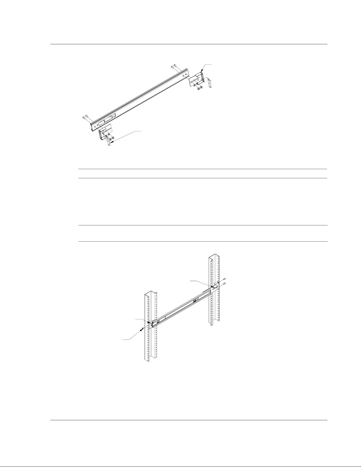
5. Attach front and rear brackets to cabinet section (see Figure 7) using the following materials
supplied with the slides:
• (4) #8 × 0.375 Flat Head Countersunk Screws SST
• (4) #8 Lock Washers
• (4) #8 Regular Washers
• (4) #8 Hex Nuts
8 M370078-05
Page 9
SPO-622 shown
Bar nut SPO-623. Install temporarily
if using Type 1, 2, 3, rails (x 2).
XG 850 Watt Rack Mount Kit Options
Figure 7
Important:
Attaching Front And Rear Bracket To Cabinet Section
Do not tighten hardware completely.
6. Mount cabinet section into rack between upright rails using:
• (4) Bar nuts (SPO-623 sold separately)
• (6) #10 × 0.375 flat head countersunk Phillips SST screw (not supplied by Jonathan).
Two for each side. See Figure 8.
Important:
equipment rack. Ensure rails are level.
SPO-622 shown
The hardware used will change depending on the type of mounting hole available in your
SPO-683 shown
Only one screw
used on front side
Figure 8
Mounting Cabinet Section Into Rack
7. Install chassis.
8. Cycle chassis twice (push in and out two times).
Ensure that rollers are engaged and the lock functions properly.
M370078-05 9
Page 10
XG 850 Watt Rack Mount Kit Options
9. Remove chassis and securely tighten hardware from step 4. See Figure 9.
lock
Figure 9
Installing Chassis
10 M370078-05
Page 11

XG 850 Watt Rack Mount Kit Options
Related Information
For related material on this product, see also:
• XG 850 Watt Series Programmable DC Power Supply Operating Manual (Part number:
M370078-01 for firmware v1.09 and below, and M370186-01 for firmware v1.11 and
higher)
• XG 850 Watt Series Programmable DC Power Supply: Quick Reference Guide (Part
number: M370078-04 for firmware 1.09 and below, and M370186-04 for firmware v1.11
and higher)
• XG 850 Watt GPIB and Ethernet Manual (Part number: M370078-06)
Trademarks
AMETEK is a registered trademark of AMETEK, Inc. Other trademarks, registered trademarks, and product names are the
property of their respective owners and are used herein for identification purposes only.
Notice of Copyright
XG 850 Watt Series Programmable DC Power Supply Rack Mount Kit Options ©December 2008 AMETEK. All rights
reserved.
Date and Revision
December 2008 Rev C
Part Number
M370078-05
Contact Information
Telephone: 1 800 733 5427 (toll free North America) or 1 858 450 0085 (direct)
Fax: 1 858 458 0267 (direct)
Email: sales@programmablepower.com or service@programmablepower.com
Web: www.programmablepower.com
Printed in USA
M370078-05 11
 Loading...