

Page 1

Half Rack
Full Rack
6 V to 600 V Models:
6-110
6-220
6-220
8-100
8-187.5
8-200
12-70
12.5-120
12-140
20-42
20-76
20-84
33-25
30-50
33-50
40-21
40-38
40-42
60-14
60-25
60-28
80-10.5
80-19
80-21
100-8.5
100-15
100-17
150-5.6
150-10
150-11.2
300-2.8
300-5
300-5.6
600-1.4
600-2.6
600-2.8
PROGRAMMABLE POWER
XG Family Programmable DC
Power Supply
Operating Manual
(firmware v 2.0 and higher)
670 Watts – 1700 Watts
M370430-01 Rev F www.programmablepower.com
Page 2

Page 3

About AMETEK
AMETEK Programmable Power, Inc., a Division of AMETEK, Inc., is a global leader in the
design and manufacture of precision, programmable power supplies for R&D, test and
measurement, process control, power bus simulation and power conditioning applications
across diverse industrial segments. From bench top supplies to rack-mounted industrial power
subsystems, AMETEK Programmable Power is the proud manufacturer of Elgar, Sorensen,
California Instruments and Power Ten brand power supplies.
AMETEK, Inc. is a leading global manufacturer of electronic instruments and
electromechanical devices with annualized sales of $2.5 billion. The Company has over 11,000
colleagues working at more than 80 manufacturing facilities and more than 80 sales and
service centers in the United States and around the world.
Trademarks
AMETEK is a registered trademark of AMETEK, Inc. Sorensen is a trademark owned by
AMETEK, Inc. Other trademarks, registered trademarks, and product names are the property
of their respective owners and are used herein for identification purposes only.
Notice of Copyright
XG Family Programmable DC Power Supply Operating Manual (firmware v 2.0 and higher) ©
2008-2014 AMETEK Programmable Power, Inc. All rights reserved.
Exclusion for Documentation
UNLESS SPECIFICALLY AGREED TO IN WRITING, AMETEK PROGRAMMABLE POWER,
INC. (“AMETEK”):
(a) MAKES NO WARRANTY AS TO THE ACCURACY, SUFFICIENCY OR SUITABILITY OF
ANY TECHNICAL OR OTHER INFORMATION PROVIDED IN ITS MANUALS OR
OTHER DOCUMENTATION.
(b) ASSUMES NO RESPONSIBILITY OR LIABILITY FOR LOSSES, DAMAGES, COSTS
OR EXPENSES, WHETHER SPECIAL, DIRECT, INDIRECT, CONSEQUENTIAL OR
INCIDENTAL, WHICH MIGHT ARISE OUT OF THE USE OF SUCH INFORMATION.
THE USE OF ANY SUCH INFORMATION WILL BE ENTIRELY AT THE USER'S RISK,
AND
(c) REMINDS YOU THAT IF THIS MANUAL IS IN ANY LANGUAGE OTHER THAN
ENGLISH, ALTHOUGH STEPS HAVE BEEN TAKEN TO MAINTAIN THE ACCURACY
OF THE TRANSLATION, THE ACCURACY CANNOT BE GUARANTEED. APPROVED
AMETEK CONTENT IS CONTAINED WITH THE ENGLISH LANGUAGE VERSION,
WHICH IS POSTED AT WWW.PROGRAMMABLEPOWER.COM.
Date and Revision
July 2015 Revision F
Part Number
M370430-01
Contact Information
Telephone: 800 733 5427 (toll free in North America)
858 450 0085 (direct)
Fax: 858 458 0267
Email: sales.ppd@ametek.com
service.ppd@ametek.com
Web: www.programmablepower.com
M370430-01 Rev F i
Page 4

Product Family: XG Family Programmable DC Power Supply
Warranty Period: Five Years
WARRANTY TERMS
AMETEK Programmable Power, Inc. (“AMETEK”), provides this written warranty covering the
Product stated above, and if the Buyer discovers and notifies AMETEK in writing of any defect
in material or workmanship within the applicable warranty period stated above, then AMETEK
may, at its option: repair or replace the Product; or issue a credit note for the defective Product;
or provide the Buyer with replacement parts for the Product.
The Buyer will, at its expense, return the defective Product or parts thereof to AMETEK in
accordance with the return procedure specified below. AMETEK will, at its expense, deliver the
repaired or replaced Product or parts to the Buyer. Any warranty of AMETEK will not apply if
the Buyer is in default under the Purchase Order Agreement or where the Product or any part
thereof:
is damaged by misuse, accident, negligence or failure to maintain the same as
specified or required by AMETEK;
is damaged by modifications, alterations or attachments thereto which are not
authorized by AMETEK;
is installed or operated contrary to the instructions of AMETEK;
is opened, modified or disassembled in any way without AMETEK's consent; or
is used in combination with items, articles or materials not authorized by AMETEK.
The Buyer may not assert any claim that the Products are not in conformity with any warranty
until the Buyer has made all payments to AMETEK provided for in the Purchase Order
Agreement.
PRODUCT RETURN PROCEDURE
1. Request a Return Material Authorization (RMA) number from the repair facility (must be
done in the country in which it was purchased):
In the USA, contact the AMETEK Repair Department prior to the return of the
product to AMETEK for repair:
Telephone: 800-733-5427, ext. 2295 or ext. 2463 (toll free North America)
858-450-0085, ext. 2295 or ext. 2463 (direct)
Outside the United States, contact the nearest Authorized Service Center (ASC). A
full listing can be found either through your local distributor or our website,
www.programmablepower.com, by clicking Support and going to the Service Centers
tab.
2. When requesting an RMA, have the following information ready:
Model number.
Serial number
Description of the problem
NOTE: Unauthorized returns will not be accepted and will be returned at the shipper's
expense.
NOTE: A returned product found upon inspection by AMETEK, to be in specification is subject
to an evaluation fee and applicable freight charges.
ii M370430-01 Rev F
Page 5
Purpose
The Operating Manual provides installation and operating information
for the XG Family Programmable DC Power Supply.
Scope
The Manual provides safety information, features and specifications,
installation procedures, functional test procedures, and operating
procedures for both local (front panel) operation and remote operation.
The Manual also provides information on the GPIB interface option and
LXI compliant Ethernet (ENET) interface for models with the MEB
options.
Audience
The Manual is intended for the user who is familiar with electronic
power supplies, Constant Voltage, Constant Current, and/or Constant
Power operating modes, and the control of output power. The user
should be familiar with practicing safe techniques while making
supply or pin connections.
Conventions Used
The following conventions are used in this guide.
WARNING
Warnings identify conditions or practices that could result in personal
injury or loss of life.
CAUTION
Cautions identify conditions or practices that could result in damage to the
unit or other equipment.
Important: Important notes provide information that is important for you
to know. They are not as serious as Warnings or Cautions.
About This Manual (firmware v2.0 and higher)
M370430-01 Rev F iii
Page 6

More information about AMETEK Programmable as well as its products and
services, is available at www.programmablepower.com.
Acronym
Definition
APG
Analog Programming
AUX
Auxiliary
ENET
Ethernet
FGA
Finished Goods Assembly
ISOL
Isolated Analog Programming
OCP
Over Current Protection
OTP
Over Temperature Protection
OVP
Over Voltage Protection
PSU
Power Supply Unit
TVS
Transient Voltage Suppressor
UVP
Under Voltage Protection
Segment
For display and readback information on the
output voltage and current displays.
Command body text
Represents SCPI commands.
About This Manual
Related Information
Acronyms
Font Conventions
This Manual uses the following typographical conventions:
iv M370430-01 Rev F
Page 7
WARNING: High energy and high voltage
Exercise caution when using a power supply. High energy levels can be stored
at the output voltage terminals on a power supply in normal operation. In
addition, potentially lethal voltages exist in the power circuit and on the output
and sense connectors of a power supply with a rated output greater than 40 V.
Filter capacitors store potentially dangerous energy for some time after power is
removed.
WARNING: Fire hazard
Operate the power supply in an environment free of flammable gases or fumes.
To ensure that the power supply's safety features are not compromised, use the
power supply as specified in this Manual and do not substitute parts or make any
unauthorized modifications. If service is necessary, please return the power
supply to the Authorized Service Center. See the Warranty on page ii.
WARNING: Limitations on use
The XG Family Programmable DC Power Supply is not intended for use in
connection with life support systems or other medical equipment or devices.
CAUTION: For use as a battery charger
When you are using a power supply for battery charging applications, it is
essential to provide an appropriately sized fuse or circuit breaker in series
between the power supply output and the battery.
Installation of a protector (fuse or DC circuit breaker), rated for about 115% of
the maximum current rating of the power supply and designed specifically to
interrupt the DC voltage of the battery, will provide adequate current protection.
Where several power supplies are in parallel, it is best to fuse each power supply
rather than use one fuse at the battery.
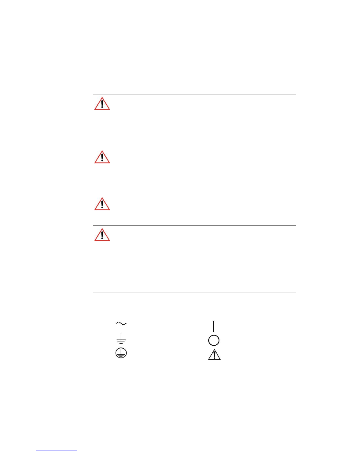
Alternating Current
On (Supply)
Earth (Ground) Terminal
Off (Supply)
Protective Conductor Terminal
Caution (Check the Manualfor
additional information.)
Important Safety Instructions
Power Supply Safety Markings
M370430-01 Rev F v
Page 8

WARNING: Keep these instructions
This chapter contains important safety and operating instructions. Read and
keep this Operating Manual for future reference.
1. Before installing and using the XG Family Programmable DC
Power Supply, read all instructions and cautionary markings on the
instrument and all appropriate sections of this Manual.
2. This instrument is for indoor use only. Do not expose the instrument
to moisture. To reduce risk of fire hazard, do not cover or obstruct
the ventilation openings. Be sure to install the instrument in a
compartment which allows air to reach the ventilation inlets on the
front and rear of the unit to prevent overheating. For more
information, see “Ventilation” on page 2-4.
3. To avoid a risk of fire and electric shock, make sure that the existing
wiring is in good condition and the wire is not undersized. Do not
operate the instrument with damaged or substandard wiring.
4. Do not operate the instrument if it has received a sharp blow, been
dropped, or otherwise damaged in any way. If the instrument is
damaged, see the Warranty on page ii.
5. Do not disassemble the instrument. It contains no user-serviceable
parts. See the Warranty on page ii for instructions on obtaining
service. Attempting to service the instrument yourself may result in
a risk of electrical shock or fire. Internal capacitors remain charged
after all power is disconnected.
6. To reduce the risk of electrical shock, disconnect AC power from
the instrument before attempting any maintenance or cleaning or
working on any circuits connected to the instrument. Turning off
controls will not reduce this risk.
Safety
Standard Warnings
vi M370430-01 Rev F
Page 9

Contents
1 INTRODUCTION ............................................................................................. 1-1
FEATURES AND OPTIONS ................................................................................... 1-2
XG MODELS (FIRMWARE VERSION 2.0 AND HIGHER) ............................................ 1-3
FRONT PANEL ................................................................................................... 1-5
Front Panel Display and Controls ........................................................................... 1-6
REAR PANEL CONNECTORS ON 850 WATT MODELS ............................................ 1-7
REAR PANEL CONNECTORS ON 1500 AND 1700 WATT MODELS ............................ 1-9
2 INSTALLATION .............................................................................................. 2-1
BASIC SETUP PROCEDURE ................................................................................ 2-2
STEP 1: INSPECTING AND CLEANING ................................................................... 2-3
Initial Inspection ...................................................................................................... 2-3
Periodic Cleaning .................................................................................................... 2-3
STEP 2: LOCATION AND MOUNTING .................................................................... 2-4
Rack Mounting ........................................................................................................ 2-4
Purchasing Rack Mount Kits ................................................................................... 2-4
Ventilation ............................................................................................................... 2-4
STEP 3: CONNECTING AC INPUT POWER ............................................................ 2-5
XG 850 Watt AC Input Connector........................................................................... 2-5
XG 1500 and 1700 Watt AC Input Connector ........................................................ 2-6
XG 1500 and 1700 Watt AC Input Wire .................................................................. 2-6
XG 1500 and 1700 Watt AC Input Wire Connection .............................................. 2-7
STEP 4: SELECTING LOAD WIRES ....................................................................... 2-8
Load Wiring ............................................................................................................. 2-8
Insulation Rating ..................................................................................................... 2-8
Current Carrying Capacity ...................................................................................... 2-8
Maximum Load Wiring Length For Operation With Sense Lines ........................... 2-9
Noise and Impedance Effects ................................................................................. 2-9
STEP 5: PERFORMING FUNCTIONAL TESTS ....................................................... 2-10
Powering the Power Supply On/Off ...................................................................... 2-10
Voltage and Current Mode Operation Checks ...................................................... 2-11
STEP 6: CONNECTING LOADS .......................................................................... 2-12
DC Output Connectors ......................................................................................... 2-12
Inductive Loads and Batteries .............................................................................. 2-13
Connecting Single Loads ...................................................................................... 2-14
Connecting Multiple Loads ................................................................................... 2-14
STEP 7: CONNECTING REMOTE SENSING .......................................................... 2-15
M370430-01 Rev F vii
Page 10

Contents
3 LOCAL OPERATION ...................................................................................... 3-1
INTRODUCTION ................................................................................................. 3-2
CONFIGURING SETTINGS FROM THE FRONT PANEL ............................................. 3-2
Using the 9-Position Mode Control ......................................................................... 3-2
Using the Rotary Adjust/Enter Control .................................................................... 3-2
Coarse and Fine Adjustment Modes ...................................................................... 3-3
NAVIGATING THE MENU SYSTEM ........................................................................ 3-4
Setting VOLTS and AMPS Modes .......................................................................... 3-4
Normal Display Mode and Inactivity Timeout ......................................................... 3-6
DISPLAY MESSAGES ON THE FRONT PANEL ........................................................ 3-8
STANDARD (LOCAL) OPERATION ...................................................................... 3-10
Operating Modes .................................................................................................. 3-10
Shipped Configuration (Local Operation) ............................................................. 3-16
ENABLING THE OUTPUT ................................................................................... 3-16
ENABLING THE AUXILIARY OUTPUT ................................................................... 3-17
OUTPUT AUTO START MODE (AUTO RESTART) ................................................. 3-17
AUXILIARY AUTO START MODE ........................................................................ 3-18
CONSTANT POWER MODE (VERSION 2.21 AND HIGHER) ..................................... 3-18
ALARMS AND ERRORS ..................................................................................... 3-20
Clearing Alarms .................................................................................................... 3-21
Front Panel ALARM LED ...................................................................................... 3-22
Alarm Masking ...................................................................................................... 3-23
Alarm Output Latching .......................................................................................... 3-24
SETTING FOLDBACK MODE .............................................................................. 3-25
Resetting Activated Foldback Protection .............................................................. 3-26
USING OVER VOLTAGE PROTECTION (OVP) ..................................................... 3-27
Defining the OVP Set Point .................................................................................. 3-28
USING UNDER VOLTAGE PROTECTION (UVP) ................................................... 3-29
Defining the UVP Set Point ................................................................................... 3-29
OVER CURRENT PROTECTION (OCP) ............................................................... 3-30
USING OVER TEMPERATURE PROTECTION LOCK (OTP) .................................... 3-31
Defining the OTP Mode ........................................................................................ 3-31
Resetting in Latch Mode ....................................................................................... 3-31
USING THE EXTERNAL SHUTDOWN FUNCTION ................................................... 3-32
Activating the External Shutdown Function .......................................................... 3-32
Controlling the External Shutdown Function ........................................................ 3-32
Defining the Polarity of the External Shutdown Signal ......................................... 3-33
LOOP PROTECTION (VERSION 2.21 AND HIGHER) ............................................... 3-33
Setting up Loop Protection ................................................................................... 3-34
INTERLOCK FUNCTION ..................................................................................... 3-35
viii M370430-01 Rev F
Page 11

Defining the Interlock Mode .................................................................................. 3-35
OUTPUT PROTECTION ..................................................................................... 3-35
Programming Voltage Output Preset .................................................................... 3-35
Programming Current Output Preset .................................................................... 3-36
Power On Status Signal ........................................................................................ 3-37
HARDWARE MALFUNCTION ALARMS ................................................................. 3-37
CURRENT CONFIGURATION MEMORY SETTINGS ................................................ 3-38
USER SETTING MEMORY LOCATIONS ............................................................... 3-39
Saving User Setting Memory Locations ............................................................... 3-40
Recalling User Setting Memory Locations ............................................................ 3-40
LOCAL LOCKOUT ............................................................................................. 3-41
Enabling Local Lockout ......................................................................................... 3-41
Disabling Local Lockout ........................................................................................ 3-41
RESETTING THE POWER SUPPLY...................................................................... 3-42
USING MULTIPLE POWER SUPPLIES ................................................................. 3-44
Configuring Multiple Supplies for Series Operation .............................................. 3-46
Configuring Multiple Supplies for Current Sharing Operation (APG Method) ...... 3-49
Connecting to the Load in Local Sensing Mode (Parallel Control Method) .......... 3-51
Connecting to the Load in Remote Sensing Mode (Parallel Control Method) ...... 3-52
Contents
4 ANALOG PROGRAMMING (APG) AND ISOLATED ANALOG
PROGRAMMING (ISOL) ................................................................................. 4-1
INTRODUCTION ................................................................................................. 4-2
Analog Programming (APG) of Output Voltage and Output Current ...................... 4-2
Remote Programming Options ............................................................................... 4-3
Analog Programming (APG) Connector J1 ............................................................ 4-5
ANALOG PROGRAMMING MODE .......................................................................... 4-9
Analog Programming With External Voltage Source .............................................. 4-9
Voltage-Controlled Voltage APG Setup ................................................................ 4-10
Voltage-Controlled Current APG Setup ................................................................ 4-12
Resistive-Controlled Voltage APG Setup ............................................................. 4-15
Resistive-Controlled Current APG Setup ............................................................. 4-17
Voltage and Current Readback ............................................................................ 4-19
ISOLATED ANALOG PROGRAMMING MODE (ISOL) ............................................. 4-20
AUX Output and Isolated Analog Programming (ISOL) Connector ...................... 4-20
Voltage-Controlled Voltage ISOL Setup ............................................................... 4-23
Voltage-Controlled Current ISOL Setup ............................................................... 4-25
Resistive-Controlled Voltage ISOL Setup ............................................................. 4-28
Resistive-Controlled Current ISOL Setup ............................................................. 4-30
VOLTAGE AND CURRENT READBACK (ISOLATED) ............................................... 4-32
M370430-01 Rev F ix
Page 12

Contents
5 REMOTE OPERATION ................................................................................... 5-1
INTRODUCTION ................................................................................................. 5-2
HARDWARE AND CONNECTION SETUP ................................................................ 5-2
Configuring Remote Control Using RS-232 ............................................................ 5-2
Configuring Remote Control Using RS-485 ............................................................ 5-7
Configuring Remote Control using the USB Connector ......................................... 5-9
Setting Up the PC to Use the USB Connection ...................................................... 5-9
GPIB Connector (Optional) ................................................................................... 5-15
Ethernet/LAN (ENET) Connector (Optional) ......................................................... 5-19
Multiple Power Supply Connections to RS-485 Bus............................................. 5-19
TERMINAL CONFIGURATION ............................................................................. 5-21
Data Format .......................................................................................................... 5-21
End of Message .................................................................................................... 5-21
HyperTerminal ...................................................................................................... 5-21
Selecting the Appropriate Communication Port .................................................... 5-24
Multichannel Address Setting ............................................................................... 5-25
Remote Interface Addressing ............................................................................... 5-26
Multichannel Commands Explained ..................................................................... 5-27
Status Reporting in SCPI ...................................................................................... 5-29
STATUS REGISTERS MODEL FROM IEEE 488.2 ................................................. 5-31
STATUS BYTE ................................................................................................. 5-32
Error/Event Queue (ERR) ..................................................................................... 5-32
Questionable Status Register Summary (QSR) ................................................... 5-32
Message Available (MAV) .................................................................................... 5-33
Standard Event Status Summary (ESB) ............................................................... 5-33
Master Summary Status (MSS) ............................................................................ 5-33
Request Service (RQS) ........................................................................................ 5-33
Operation Status Register Summary (OSR) ......................................................... 5-34
Standard Event Status Register (SESR) .............................................................. 5-35
STANDARD SCPI REGISTER STRUCTURE ......................................................... 5-38
OPERATION STATUS REGISTER ...................................................................... 5-39
CURRENT SHARE SUB-REGISTER .................................................................... 5-42
Operation Status Register Commands ................................................................. 5-43
Current Sharing Sub-Register Commands ........................................................... 5-44
Shutdown Sub-Register Commands .................................................................... 5-45
Protection Sub-Register Commands .................................................................... 5-46
QUESTIONABLE STATUS REGISTER ................................................................. 5-47
VOLTage Sub-Register ........................................................................................ 5-50
TEMPerature Sub-Register .................................................................................. 5-50
Questionable Status Register Commands ........................................................... 5-51
x M370430-01 Rev F
Page 13

Voltage Status Register Commands..................................................................... 5-52
Temperature Status Register Commands ............................................................ 5-53
SCPI ERROR/EVENT QUEUE ........................................................................... 5-54
Reset Command ................................................................................................... 5-56
Clear All Status Registers ..................................................................................... 5-57
SCPI Preset Status ............................................................................................... 5-58
Command Line Help System ................................................................................ 5-59
LOCKING AND UNLOCKING THE FRONT PANEL ................................................... 5-62
Auto Sequence Programming ............................................................................... 5-62
CONFIGURE OTHER PROTECTION MECHANISMS ................................................ 5-68
Foldback Protection .............................................................................................. 5-68
Over Temperature Protection ............................................................................... 5-69
Loop Protection Enable/Disable ........................................................................... 5-69
Interlock Enable/Disable ....................................................................................... 5-70
Save and Recall .................................................................................................... 5-71
Set Analog Programming Level ............................................................................ 5-71
Set Remote Programming Interface ..................................................................... 5-72
Protection Mask (Enable Alarms) ......................................................................... 5-73
Power Saving Control (Sleep Mode, XG 1700 W Only) ....................................... 5-74
Contents
6 COMMUNICATIONS OPTIONS ...................................................................... 6-1
INTRODUCTION ............................................................................................. 6-2
SETTING UP LAN/ETHERNET ....................................................................... 6-3
Basics ..................................................................................................................... 6-3
LOCAL AREA NETWORK (LAN) OPTION ....................................................... 6-5
Media Access Control (MAC) Address ................................................................... 6-5
Communication Configuration ................................................................................ 6-6
LAN Connection ...................................................................................................... 6-6
Direct-to-PC Connection ......................................................................................... 6-6
Private Network Connection ................................................................................... 6-7
CONNECTING TO A NETWORK .................................................................... 6-8
Connecting with PC on Same Side of Router as Power Supply ............................ 6-8
Connecting with Power Supply Hidden Behind a Router ..................................... 6-10
Socket Port Number.............................................................................................. 6-12
Instrument Drivers and Application Software ....................................................... 6-13
AMETEK LXI DISCOVERY BROWSER ......................................................... 6-13
Installing the AMETEK LXI Discovery Browser .................................................... 6-13
Using the AMETEK LXI Discovery Browser ......................................................... 6-21
AMETEK ENETTEST UTILITY ......................................................................... 6-22
Installing the AMETEK EnetTest Utility................................................................. 6-22
Using the AMETEK Ethernet Test Utility .............................................................. 6-28
M370430-01 Rev F xi
Page 14

Contents
SETTING LAN PARAMETERS ...................................................................... 6-29
Setting LAN Parameters via Ethernet ................................................................... 6-29
Setting LAN Parameters via Serial or USB Port ................................................... 6-29
Setting LAN Parameters via Web Interface .......................................................... 6-30
SETTING A STATIC IP ADDRESS THROUGH ETHERNET, USB, SERIAL INTERFACES
...................................................................................................................... 6-35
Ethernet ................................................................................................................ 6-35
USB ....................................................................................................................... 6-36
RS232 (SERIAL) ................................................................................................... 6-44
SYSTEM COMMANDS.................................................................................. 6-53
Subsystem Syntax ................................................................................................ 6-53
LXI COMPLIANCE ........................................................................................ 6-56
Introduction to the LXI Standard ........................................................................... 6-57
VXI Discovery ....................................................................................................... 6-57
LAN Requirements................................................................................................ 6-57
Web Page ............................................................................................................. 6-57
Remote Procedure Calls (RPC) ............................................................................ 6-58
Drivers ................................................................................................................... 6-58
7 CALIBRATION AND TROUBLESHOOTING .................................................. 7-1
INTRODUCTION ................................................................................................. 7-2
MAIN VOLTAGE AND CURRENT CALIBRATION PRINCIPLE ...................................... 7-3
Understanding the Problem .................................................................................... 7-3
Step 1: Gain Calibration .......................................................................................... 7-4
Step 2: Offset Calibration ........................................................................................ 7-4
Step 3: Recalibrate Gain ......................................................................................... 7-5
STORING CALIBRATION DATA ............................................................................. 7-5
CALIBRATING THE OUTPUT VOLTAGE.................................................................. 7-6
Gain Calibration ...................................................................................................... 7-6
Offset Calibration .................................................................................................... 7-6
CALIBRATING THE OUTPUT CURRENT ................................................................. 7-7
Gain Calibration ...................................................................................................... 7-7
Offset Calibration .................................................................................................... 7-8
OVER VOLTAGE PROTECTION CALIBRATION ........................................................ 7-9
NON-ISOLATED ANALOG PROGRAMMING CALIBRATION ...................................... 7-10
Non-isolated Voltage Monitoring Calibration ........................................................ 7-10
Non-isolated Current Monitoring Calibration ........................................................ 7-11
Non-isolated Voltage Programming of Voltage Calibration .................................. 7-12
Non-isolated Resistive Programming of Voltage Calibration ................................ 7-13
Non-isolated Voltage Programming of Current Calibration .................................. 7-14
Non-isolated Resistive Programming of Current Calibration ................................ 7-15
xii M370430-01 Rev F
Page 15

CALIBRATION PROCEDURE FOR ISOLATED MODES ............................................ 7-16
Isolated Voltage Monitoring Calibration ................................................................ 7-16
Isolated Current Monitoring Calibration ................................................................ 7-17
Isolated Voltage Programming of Voltage Calibration .......................................... 7-18
Isolated Resistive Programming of Voltage Calibration ....................................... 7-19
Isolated Voltage Programming of Current Calibration .......................................... 7-20
Isolated Resistive Programming of Current Calibration........................................ 7-21
Calibrating the Input Voltage APG Signal ............................................................. 7-22
Calibrating the Input Current APG Signal ............................................................. 7-23
RESTORE FACTORY CALIBRATION .................................................................... 7-25
RESTORE DEFAULT CALIBRATION .................................................................... 7-25
USER DIAGNOSTICS ........................................................................................ 7-25
Emergency Shutdown ........................................................................................... 7-26
Unusual or Erratic Operation ................................................................................ 7-26
Troubleshooting for Operators .............................................................................. 7-27
APPENDIX A SCPI COMMAND REFERENCE .................................................... A-1
SCPI CONFORMANCE INFORMATION ................................................................. A-2
Codes and Standards ............................................................................................ A-2
IEEE 488.2/SCPI Syntax and Style ....................................................................... A-2
SCPI Command Hierarchy .................................................................................... A-3
Using SCPI Commands ......................................................................................... A-4
Parameter Types ................................................................................................... A-7
SCPI COMMAND TREE ..................................................................................... A-8
SCPI Command Summary .................................................................................. A-14
APPENDIX B ERROR MESSAGES ................................................................... B-1
ERROR MESSAGES .......................................................................................... B-2
Command Error List ............................................................................................... B-3
Execution Error List................................................................................................ B-4
Device-Specific Error List ...................................................................................... B-5
Query Error List ...................................................................................................... B-6
APPENDIX C SPECIFICATIONS ....................................................................... C-1
ELECTRICAL SPECIFICATIONS FOR XG FAMILY, 850 W ....................................... C-2
AC Line Input Specifications for XG 850 Watt ....................................................... C-3
ELECTRICAL SPECIFICATIONS FOR XG FAMILY, 1500 W ..................................... C-4
AC Line Input Specifications for XG 1500 Watt ..................................................... C-5
ELECTRICAL SPECIFICATIONS FOR XG FAMILY, 1700 W ..................................... C-6
AC Line Input Specifications for XG 1700 Watt ..................................................... C-7
REMOTE OPERATION PROGRAMMING ................................................................ C-8
COMMON SPECIFICATIONS FOR ALL MODELS ................................ ..................... C-9
APPENDIX D RACK MOUNT OPTIONS AND INSTALLATION INSTRUCTIONS.......... D-1
Contents
M370430-01 Rev F xiii
Page 16

Contents
RACK MOUNT KIT OPTIONS .............................................................................. D-2
XG Single (Half Rack) and Dual (Full Rack) .......................................................... D-2
Location Requirements .......................................................................................... D-3
MOUNTING OPTION A: 1U RAILS ....................................................................... D-4
Tools and Materials Required ................................................................................ D-4
Installation Procedures .......................................................................................... D-4
MOUNTING OPTION B: MANUFACTURED SLIDES FROM JONATHAN® ENGINEERED
SOLUTIONS ...................................................................................................... D-6
APPENDIX E LANTRONIX PROCEDURES FOR MEA OPTION ............................. E-1
INTRODUCTION ................................................................................................ E-2
Setting Up the Computer ....................................................................................... E-2
Software Installations ............................................................................................. E-4
Configuring the Device Using DeviceInstaller ....................................................... E-6
Terminal Configuration ........................................................................................ E-12
Advanced Section ................................................................................................ E-17
Network Topology 1: Simple LAN ........................................................................ E-17
Network Topology 2: ENET and RS-485 Bus ...................................................... E-20
Troubleshooting for XG 850W Model with ENET and/or RS-485 Communication
............................................................................................................................. E-23
INDEX .................................................................................................................. 1
Figures
Figure 1-1 XG Front Panels (Half Rack, above; Full Rack, below; not to-scale) ............. 1-5
Figure 1-2 Front Panel Display and Controls ................................................................... 1-6
Figure 1-3 XG 850 Watt Units: 6 V to 40 V Models .......................................................... 1-7
Figure 1-4 XG 850 Watt Units: 60 V to 150 V Models ..................................................... 1-7
Figure 1-5 XG 850 Watt Units: 300 V to 600 V Models .................................................... 1-7
Figure 1-6 XG 1500 and 1700 Watt Units: 6 V to 40 V Models ........................................ 1-9
Figure 1-7 XG 1500 and 1700 Watt Units: 60 V to 600 V Models .................................. 1-10
Figure 2-1 1500 and 1700 Watt AC Input Cover and Strain Relief .................................. 2-6
Figure 2-2 Maximum Load Wire Length for 1 V Line Drop ............................................... 2-9
Figure 2-3 Diode Placement ........................................................................................... 2-13
Figure 2-4 Connecting Single Loads .............................................................................. 2-14
Figure 2-5 Remote Sense Connection ........................................................................... 2-15
Figure 3-1 9-Position Mode Control .................................................................................. 3-2
Figure 3-2 Front Panel Menu System ............................................................................... 3-7
Figure 3-3 Operating Modes ........................................................................................... 3-13
Figure 3-4 Split Supply Operation .................................................................................. 3-45
Figure 3-5 Series Operation ........................................................................................... 3-47
Figure 3-6 Load Connections in Remote Sensing Mode ................................................ 3-48
Figure 3-7 Load Connections in Local Sensing Mode .................................................... 3-51
Figure 3-8 Load Connections in Remote Sensing Mode (Parallel Control Method) ...... 3-52
Figure 4-1 APG Connector Terminals .............................................................................. 4-5
Figure 4-2 Inserting Screwdriver into Spring Terminal Block ........................................... 4-7
Figure 4-3 APG and DC Output Connector ...................................................................... 4-7
xiv M370430-01 Rev F
Page 17

Contents
Figure 4-4 Programming Output Voltage using an External Voltage Source ................... 4-9
Figure 4-5 Programming Output Current using an External Voltage Source ................... 4-9
Figure 4-6 Programming Output Voltage using an External Resistor ............................ 4-14
Figure 4-7 Programming Output Current using an External Resistor ............................ 4-14
Figure 4-8 Voltage Readback Using APG Connector J1 ............................................... 4-19
Figure 4-9 Current Readback Using APG Connector J1 ................................................ 4-19
Figure 4-10 AUX Output and ISOL Connector Pinout ...................................................... 4-20
Figure 4-11 Programming Output Voltage using an Isolated External Voltage Source ... 4-22
Figure 4-12 Programming Output Current using an Isolated External Voltage Source ... 4-22
Figure 4-13 Programming Output Voltage using an Isolated External Resistor .............. 4-27
Figure 4-14 Programming Output Current using an Isolated External Resistor ............... 4-27
Figure 4-15 Isolated Voltage Monitoring........................................................................... 4-32
Figure 4-16 Isolated Current Monitoring ........................................................................... 4-32
Figure 5-1 Remote Control Connectors............................................................................ 5-3
Figure 5-2 RS-232 Communication Cable with DB-9 Pinout............................................ 5-5
Figure 5-3 DB-25 Pinout ................................................................................................... 5-5
Figure 5-4 RS-232 Communication Cable with DB-25 Pinout.......................................... 5-6
Figure 5-5 RS-485 Communication Cable with DB-9 ....................................................... 5-7
Figure 5-6 RS-485 Communication Cable from Master to Slave Unit .............................. 5-8
Figure 5-7 Found New Hardware Wizard ....................................................................... 5-10
Figure 5-8 Install Hardware Device Drivers .................................................................... 5-10
Figure 5-9 Completing the New Hardware Wizard ......................................................... 5-11
Figure 5-10 Device Manager ............................................................................................ 5-12
Figure 5-11 Communications Port (COM1) Properties .................................................... 5-13
Figure 5-12 Completing the new hardware wizard ........................................................... 5-13
Figure 5-13 Scanning for Instruments .............................................................................. 5-17
Figure 5-14 Instrument Properties ................................................................................... 5-18
Figure 5-15 Multi Power Supply Connection to RS-485 Bus............................................ 5-19
Figure 5-16 USB Settings ................................................................................................. 5-22
Figure 5-17 ASCII Setup .................................................................................................. 5-23
Figure 5-18 SCPI Status Reporting Model ....................................................................... 5-30
Figure 5-19 IEEE 488.2 Register Model ........................................................................... 5-31
Figure 5-20 Summary of Standard Event Status Register ............................................... 5-36
Figure 5-21 SCPI Register Model ..................................................................................... 5-38
Figure 5-22 Operation Status Register Fanout ................................................................ 5-39
Figure 5-23 SCPI QUEStionable Registers Fanout ......................................................... 5-48
Figure 6-1 Computer or HUB Plug ................................................................................... 6-3
Figure 6-2 Power Supply Plug .......................................................................................... 6-3
Figure 6-3 RJ-45 Plug....................................................................................................... 6-3
Figure 6-4 Scheme of ENET Cross-Cable ....................................................................... 6-4
Figure 6-5 XPort® ENET Connector and LEDs ............................................................... 6-4
Figure 6-6 Single Computer, Single Power Supply .......................................................... 6-6
Figure 6-7 PC on Same Side of Router as Power Supply................................................ 6-8
Figure 6-8 Home Page ..................................................................................................... 6-9
Figure 6-9 AMETEK LXI Discovery Browser .................................................................... 6-9
Figure 6-10 Power Supply Hidden Behind a Router ........................................................ 6-10
Figure 6-11 Router Home Page ....................................................................................... 6-11
Figure 6-12 Port Forwarding ............................................................................................. 6-12
Figure 7-1 Offset (Intercept) Error and Gain (Slope) Error ............................................... 7-3
Figure 7-2 Calibration: Step 1 Gain Calibration ................................................................ 7-4
Figure 7-3 Calibration: Step 2 Offset Calibration .............................................................. 7-4
Figure 7-4 Calibration: Step 3 Recalibrate Gain ............................................................... 7-5
M370430-01 Rev F xv
Page 18

Contents
Figure C-1 XG 850 Watt Mechanical Dimensions: 6 to 40 V Models ............................ C-11
Figure C-2 XG 850 Watt Mechanical Dimensions: 60 V to 600 V Models ..................... C-12
Figure C-3 XG in Full Rack Mechanical Dimensions: 6 V to 40 V Models .................... C-13
Figure C-4 XG in Full Rack Mechanical Dimensions: 6 V to 40 V Models DC Output Cover
C-14
Figure C-5 XG in Full Rack Mechanical Dimensions: 60 V to 600 V Models ................ C-15
Figure C-6 XG in Full Rack Mechanical Dimensions: 60 V to 600 V Models w/DC Output
Cover ............................................................................................................ C-16
Figure C-7 XG850 with Full Rack and Foot Options, Front, Side, and Rear Views ...... C-17
Figure C-8 XG850 Standard in Full Rack Option ........................................................... C-17
Figure C-9 XG850 Low Voltage Model Dimensions, Top, Side, and Rear .................... C-18
Figure C-10 XG850 Medium and High Voltage Models Dimensions, Top and Rear ....... C-19
Figure C-11 XG850 with Front Panel Output Voltage Option*, Top, Side, and Rear ....... C-20
Figure D-1 Single (left,) and Dual (right) Half Rack Mount Kit Options ............................ D-2
Figure D-2 Full Rack Mount Kit Option ............................................................................. D-3
Figure D-3 RM-XG1 Rack Rails ....................................................................................... D-5
Figure D-4 Finding Rack Depth ........................................................................................ D-6
Figure D-5 Selecting a Rail Type...................................................................................... D-7
Figure D-6 Modifying Rear Bracket .................................................................................. D-8
Figure D-7 Removing Chassis Member From Slides ....................................................... D-8
Figure D-8 Attaching Front and Rear Bracket To Cabinet Section .................................. D-9
Figure D-9 Mounting Cabinet Section Into Rack ............................................................ D-10
Figure D-10 Installing Chassis .......................................................................................... D-11
Figure E-1 Configuring the Network Connection of the Computer ................................... E-2
Figure E-2 LAN Properties Dialog Box ............................................................................. E-3
Figure E-3 Internet Protocol (TCP/IP) Properties Dialog Box .......................................... E-4
Figure E-4 DeviceInstaller Setup Wizard ......................................................................... E-5
Figure E-5 Select Installation Folder Window .................................................................. E-6
Figure E-6 Multiple Network Adapters ............................................................................. E-7
Figure E-7 Selecting Network Adapter ............................................................................. E-7
Figure E-8 Auto-IP Address Message .............................................................................. E-8
Figure E-9 Searching for Power Supply IP Address ........................................................ E-8
Figure E-10 IP Address Details Window ............................................................................ E-9
Figure E-11 Entering the Lantronix Interface ................................................................... E-10
Figure E-12 Lantronix XPort® Interface ........................................................................... E-10
Figure E-13 Assigning IP Settings ................................................................................... E-11
Figure E-14 HyperTerminal Connection ........................................................................... E-13
Figure E-15 Connection Description Window .................................................................. E-13
Figure E-16 New Connection Dialog Box ......................................................................... E-14
Figure E-17 Main Terminal Window ................................................................................. E-15
Figure E-18 ENET Properties Window ............................................................................. E-15
Figure E-19 ENET Properties Dialog Box ........................................................................ E-16
Figure E-20 ASCII Setup Dialog Box ............................................................................... E-17
Figure E-21 Multiple Power Supplies and Two Computers ............................................. E-18
Figure E-22 HyperTerminal Session ................................................................................ E-19
Figure E-23 System with Two Connected Devices .......................................................... E-20
Figure E-24 ENET and RS-485 Bus ................................................................................ E-21
Figure E-25 HyperTerminal Window ................................................................................ E-21
xvi M370430-01 Rev F
Page 19

Contents
Tables
Table 1-1 XG 850 Watt Series Voltage and Current Ranges ......................................... 1-3
Table 1-2 XG 1500 Watt Series Voltage and Current Ranges ....................................... 1-4
Table 1-3 XG 1700 Watt Series Voltage and Current Ranges ....................................... 1-4
Table 2-1 Basic Setup Procedure ................................................................................... 2-2
Table 2-2 XG 1500 and 1700 Watt: Recommended AC Input Wire (higher power) ....... 2-6
Table 2-3 Current Carrying Capacity for Load Wiring ..................................................... 2-8
Table 3-1 Select and Set from the Front Panel ............................................................... 3-3
Table 3-2 Front Panel Display Text ................................................................................. 3-8
Table 3-3 Shipped Configuration ................................................................................... 3-16
Table 3-4 Alarm Order of Precedence .......................................................................... 3-20
Table 3-5 Alarm Mask Bit Positions .............................................................................. 3-23
Table 3-6 Alarm Latch Bit Positions .............................................................................. 3-24
Table 3-7 Power Cycle Saved/Recalled Settings .......................................................... 3-38
Table 3-8 User Accessible Saved/Recalled Settings Voltage Setpoint ........................ 3-39
Table 3-9 Power Supply Default Settings...................................................................... 3-42
Table 4-1 Monitor Lines ................................................................................................... 4-3
Table 4-2 Remote Programming Options........................................................................ 4-4
Table 4-3 APG Pins and Functions J1 ............................................................................ 4-5
Table 4-4 AUX Output and ISOL Connector Pins and Functions J3 ............................ 4-21
Table 5-1 Remote Control Connector Pins and Functions J4 and J61............................ 5-3
Table 5-2 DB-9 Pinouts ................................................................................................... 5-4
Table 5-3 RJ-45 Pinouts .................................................................................................. 5-4
Table 5-4 DB-25 Pinouts ................................................................................................. 5-5
Table 5-5 DB-9 Pinouts ................................................................................................... 5-7
Table 5-6 RJ-45 Plug Pinouts ......................................................................................... 5-7
Table 5-7 RJ-45 Plug on Slave Unit ................................................................................ 5-8
Table 5-8 GPIB Pin Description (J2) ............................................................................. 5-15
Table 5-9 Rules for Multichannel Responses ............................................................... 5-27
Table 5-10 Status Byte Summary Register ..................................................................... 5-32
Table 5-11 Standard Event Status Register .................................................................... 5-36
Table 5-12 OPERation Status Register........................................................................... 5-40
Table 5-13 OPERation SHUTdown Status Register ....................................................... 5-41
Table 5-14 OPERation SHUTdown PROTection Status Register .................................. 5-41
Table 5-15 OPERation CSHare Status Register ............................................................. 5-42
Table 5-16 QUEStionable Status Register ...................................................................... 5-49
Table 5-17 QUEStionable VOLTage Status Register ..................................................... 5-50
Table 5-18 QUEStionable TEMPerature Status Register ............................................... 5-50
Table 5-19 Preset Values of User Configurable Registers ............................................. 5-58
Table 5-20 Alarms Bit Mask ............................................................................................ 5-73
Table 6-1 Description of Pins on RJ-45 Plug .................................................................. 6-4
Table 6-2 Description of LEDs ........................................................................................ 6-5
Table 6-3 LAN Setting Screens ..................................................................................... 6-32
Table 6-4 Factory Default LAN Settings ........................................................................ 6-57
Table 7-1 Troubleshooting ............................................................................................ 7-27
Table A-1 IEEE 488.2 Commands ................................................................................ A-14
Table A-2 Readback Commands .................................................................................. A-16
Table A-3 SCPI Commands for Output Control ............................................................ A-17
Table A-4 SCPI Commands for Calibration .................................................................. A-18
Table A-5 SCPI Commands to Clear All Protection Mechanisms ................................ A-21
M370430-01 Rev F xvii
Page 20

Contents
Table A-6 SCPI Commands for Foldback Protection ................................................... A-22
Table A-7 SCPI Commands for Power ......................................................................... A-23
Table A-8 SCPI Commands for Triggering ................................................................... A-23
Table A-9 System Commands ...................................................................................... A-24
Table A-10 Status Commands ........................................................................................ A-27
Table A-11 Protection Commands .................................................................................. A-35
Table A-12 Auto Sequence Commands ......................................................................... A-35
Table B-1 Command Error List ....................................................................................... B-3
Table B-2 Execution Error List ........................................................................................ B-4
Table B-3 Device-Specific Error List ............................................................................... B-5
Table B-4 Query Error List .............................................................................................. B-6
Table C-1 XG 850 Watt Electrical Specifications for 6 V to 600 V Models ..................... C-2
Table C-2 XG 1500 Watt Electrical Specifications for 6 V to 600 V Models ................... C-4
Table C-3 XG 1700 Watt Electrical Specifications for 6 V to 600 V Models ................... C-6
Table C-4 Remote Operation Programming ................................................................... C-8
Table C-5 Output Performance Specifications ............................................................... C-9
Table D-1 Table Rack Mount Options............................................................................. D-2
Table D-2 Part Numbers for Jonathan Manufactured Slides .......................................... D-7
Table E-1 Troubleshooting for the Combined ENET – RS-485 Communication ......... E-23
Table E-2 Troubleshooting for ENET Communication ................................................. E-24
xviii M370430-01 Rev F
Page 21

1
Introduction
Chapter 1, Introduction, describes the features of the XG Family
Programmable DC Power Supply.
Page 22

The XG Family Programmable DC Power Supply provides stable,
variable output voltage and current for a broad range of development and
system requirements. The power supplies have a high power density and
numerous industry standard interfaces:
RS-232, RS-485, analog programming (APG), and USB built-in
ports.
Optional GPIB or Ethernet (ENET), isolated analog programming
(ISOL), control for remote operation and readback.
Seamless switching between front panel and any digital interface
(RS-232, RS-485, USB, GPIB or ENET).
Simultaneous digital displays for both voltage and current.
Front panel control by rotary Adjust/Enter knob, permitting high
resolution output setting.
Active Power Factor Correction (PFC) reduces input current and
input current harmonics.
Automatic crossover system allowing the power supply to switch
between Constant Current, Constant Voltage and Constant Power
(available in version 2.21 and higher) operating modes.
Parallel or series connection among multiple units to produce
greater diversity or to use in higher power applications.
Short-circuit protection of DC outputs provideing greater operating
safety.
Built-in APG and ISOL (optional) interface to provide a
galvanically isolated analog voltage control of the output,
master/slave output tracking, and remote Enable/disable for safety
and precision.
Remote output voltage sensing to automatically compensate for
cable losses.
Software calibrated.
Three user setting memory locations.
M10 Option preprograms the voltage to reset to zero upon power on
and upon output enable.
Introduction
Features and Options
1-2 M370430-01 Rev F
Page 23

1
Model
Output Voltage
Output Current
6-110
0-6 V
0-110 A
8-100
0-8 V
0-100 A
12-70
0-12 V
0-70 A
20-42
0-20 V
0-2 A
33-25
0-33 V
0-25 A
40-21
0-40 V
0-21 A
60-14
0-60 V
0-14 A
80-10.5
0-80 V
0-10.5 A
100-8.5
0-100 V
0-8.5 A
150-5.6
0-150 V
0-5.6 A
300-2.8
0-300 V
0-2.8 A
600-1.4
0-600 V
0-1.4 A
XG Models (firmware version 2.0 and higher)
Table 1-1 lists the models in the XG 850 Watt series covered by this
Manual.
Table 1-1 XG 850 Watt Series Voltage and Current Ranges
Introduction
M370430-01 Rev F 1-3
Page 24

Model
Output Voltage
Output Current
6-220
0-6 V
0-220 A
8-187.5
0-8 V
0-187.5 A
12.5-120
0-12.5 V
0-120 A
20-76
0-20 V
0-76 A
30-50
0-30 V
0-50 A
40-38
0-40 V
0-38 A
60-25
0-60 V
0-25 A
80-19
0-80 V
0-19A
100-15
0-100 V
0-15 A
150-10
0-150 V
0-10 A
300-5
0-300 V
0-5 A
600-2.6
0-600 V
0-2.6 A
Model
Output Voltage
Output Current
6-220
0-6 V
0-220 A
8-200
0-8 V
0-200 A
12-140
0-12 V
0-140 A
20-84
0-20 V
0-84 A
33-50
0-33 V
0-50 A
40-42
0-40 V
0-42 A
60-28
0-60 V
0-28 A
80-21
0-80 V
0-21 A
100-17
0-100 V
0-17 A
150-11.2
0-150 V
0-11.2 A
300-5.6
0-300 V
0-5.6 A
600-2.8
0-600 V
0-2.8 A
Introduction
Table 1-2 lists the models in the XG 1500 Watt series covered by this
Manual.
Table 1-2 XG 1500 Watt Series Voltage and Current Ranges
Table 1-3 lists the models in the XG 1700 Watt series covered by this
Manual.
Table 1-3 XG 1700 Watt Series Voltage and Current Ranges
1-4 M370430-01 Rev F
Page 25
1
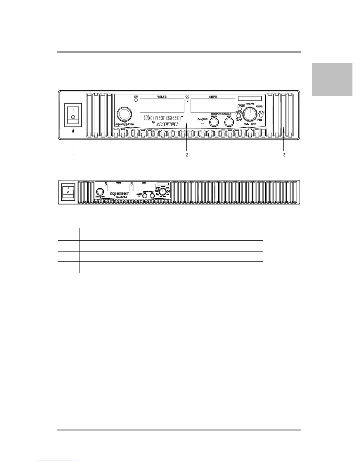
Item
Description
1
Front panel power switch
2
Front panel display see Figure 1-2
3
Air Intake Vents
Front Panel
Introduction
Figure 1-1 XG Front Panels (Half Rack, above; Full Rack, below; not to-scale)
M370430-01 Rev F 1-5
Page 26
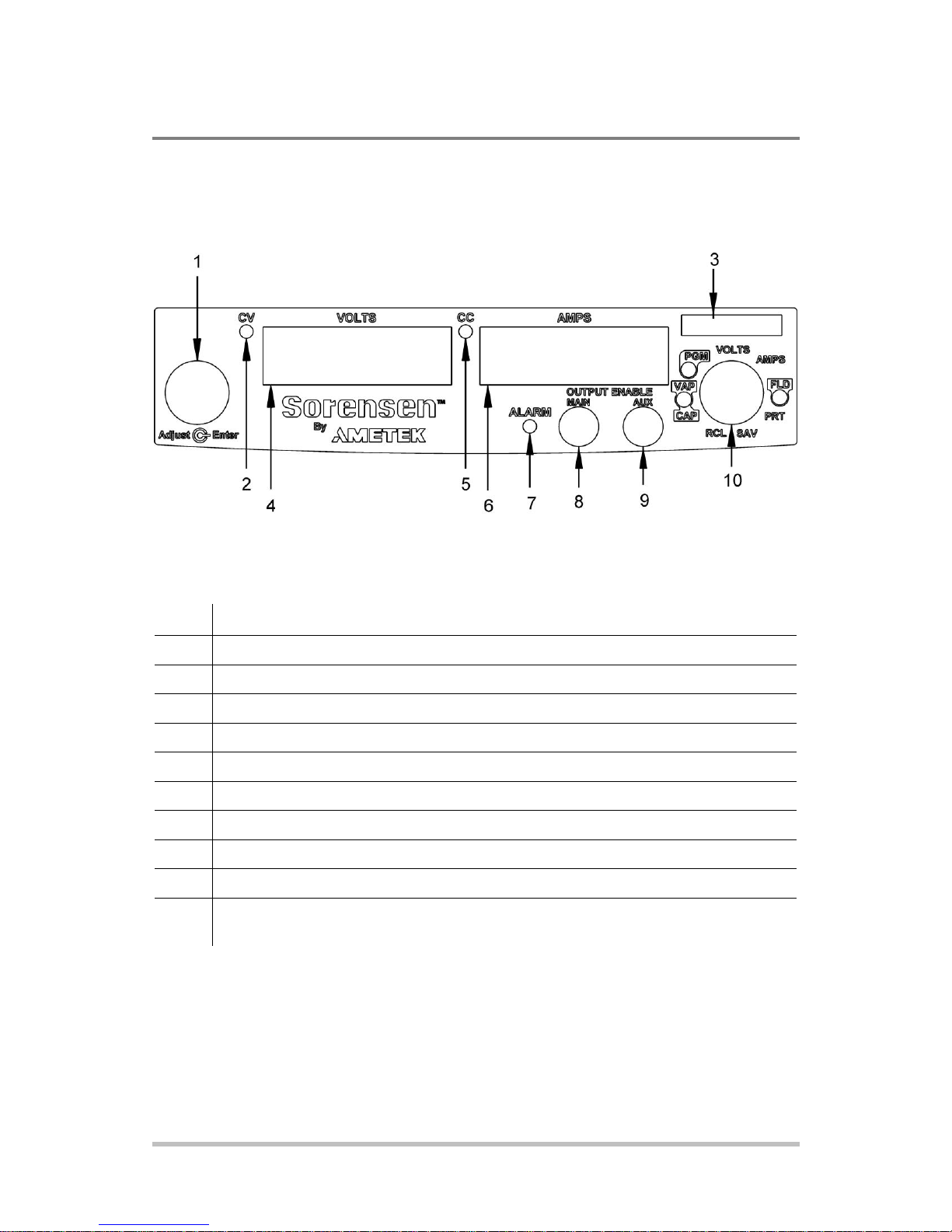
Item
Description
1
Rotary Adjust/Enter control
2
Constant Voltage (CV) Mode LED (green)
3
Model Identification Label
4
Output Voltage Display
5
Constant Current (CC) Mode LED (green)
6
Output Current Display
7
Alarm Indicator LED (red)
8
OUTPUT ENABLE Main button
9
OUTPUT ENABLE Aux button
10
9-Position Mode Control (For detailed information, see “Configuring Settings from the Front
Panel” on page 3-2).
Introduction
Front Panel Display and Controls
Figure 1-2 Front Panel Display and Controls
1-6 M370430-01 Rev F
Page 27
1
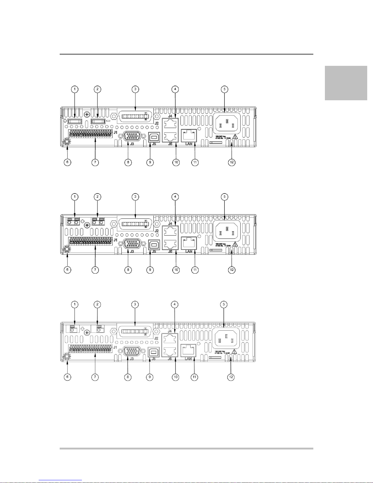
Rear Panel Connectors on 850 Watt Models
Figure 1-3 XG 850 Watt Units: 6 V to 40 V Models
Introduction
Figure 1-4 XG 850 Watt Units: 60 V to 150 V Models
Figure 1-5 XG 850 Watt Units: 300 V to 600 V Models
M370430-01 Rev F 1-7
Page 28

Item
Description
1
6 V– 40 V Models: DC Output Terminal Positive
60 V–150 V Models: DC Output Connectors Positive (6.5 mm hole diameter)
300 V–600 V Models: DC Output Connectors Positive (6.5 mm hole diameter)
2
6 V– 40 V Models: DC Output Terminal Negative
60 V–150 V Models: DC Output Connectors Negative (6.5 mm hole diameter)
300 V–600 V Models: DC Output Connectors Negative (6.5 mm hole diameter)
3 (J2)
Ethernet (ENET) or GPIB Connector (optional)
4 (J4)
RS-232/RS-485 Connector In Port
5
AC Input Connector (IEC Type)
6
Chassis Ground Stud
7 (J1)
Analog Programming (APG) Connector. For pin information, see page 4-5.
8 (J3)
AUX Output and Isolated Analog Programming (ISOL) Connector. For pin information, see
page 4-20.
9 (J5)
USB Connector
10 (J6)
RS-485 Connector Multichannel Port
11
Ethernet/LAN (option) Connector
12
Fan Exhaust Vents
Introduction
1-8 M370430-01 Rev F
Page 29
1
Introduction
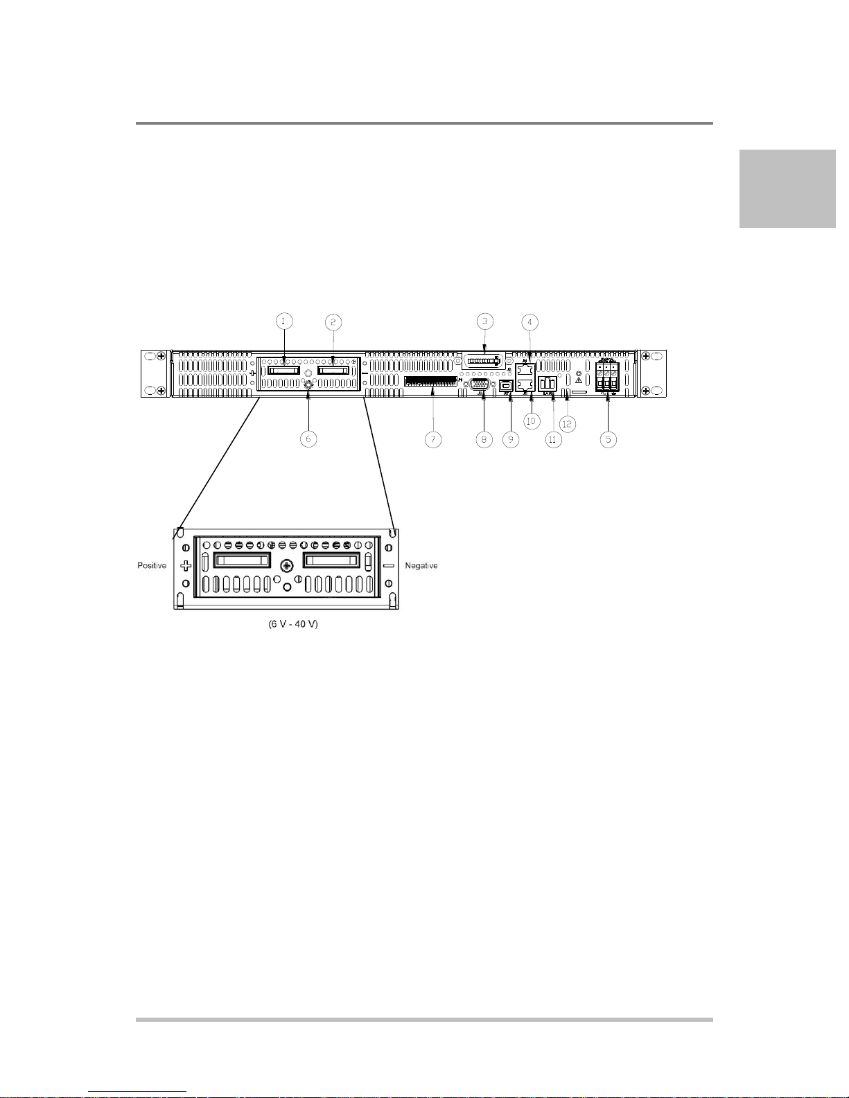
Rear Panel Connectors on 1500 and 1700 Watt
Models
Figure 1-6 XG 1500 and 1700 Watt Units: 6 V to 40 V Models
M370430-01 Rev F 1-9
Page 30
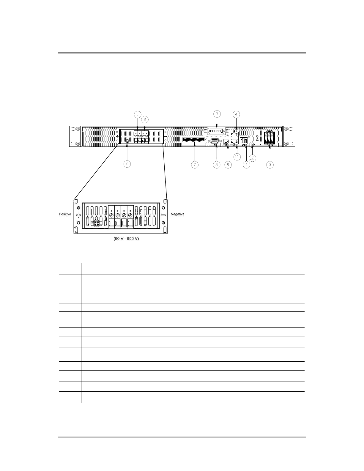
Item
Description
1
6 V– 40 V Models: DC Output Terminal Positive (8.5 mm hole diameter)
60 V–600 V Models: DC Output Connectors Positive
2
6 V– 40 V Models: DC Output Terminal Negative (8.5 mm hole diameter)
60 V–600 V Models: DC Output Connectors Negative
3 (J2)
Ethernet (ENET) or GPIB Connector (optional)
4 (J4)
RS-232/RS-485 Connector In Port
5
AC Input Terminal
6
Chassis Ground Stud
7 (J1)
Analog Programming (APG) Connector. For pin information, see page 4–5.
8 (J3)
AUX Output and Isolated Analog Programming (ISOL) Connector. For pin information, see
page 4–20.
9 (J5)
USB Connector
10 (J6)
RS-485 Connector Multichannel Port
11
Ethernet Connector
12
Fan Exhaust Vents
Introduction
Figure 1-7 XG 1500 and 1700 Watt Units: 60 V to 600 V Models
1-10 M370430-01 Rev F
Page 31

2
Installation
Chapter 2, Installation, provides information and
procedures for inspecting, installing, and testing the power
supply.
Page 32

Step
Description
Action
Reference
1
Inspect
Inspect the power supply.
“Step 1: Inspecting and Cleaning”
on page 2-3.
2
Install
Install the power supply
(benchtop or rack mount).
Ensure adequate ventilation.
“Step 2: Location and Mounting” on
page 2-4.
3
Connect Input
Power
Connect AC input power.
“Step 3: Connecting AC Input
Power” on page 2-5.
4
Select Wires
Select wires that are correctly
rated for the maximum DC
output current.
“Step 4: Selecting Load Wires” on
page 2-8.
5
Te s t
Perform functional tests for
voltage mode operation, current
mode operation, and front panel
controls.
“Step 5: Performing Functional
Tests” on page 2-10.
6
Connect Loads
Connect the load wires to the
DC output.
“Step 6: Connecting Loads” on
page 2-12.
7
Connect Remote
Sensing (if
required)
Connect remote sensing
connectors on power supply to
load.
“Step 7: Connecting Remote
Sensing” on page 2-15.
Installation
Basic Setup Procedure
Table 2-1 provides a summary of the basic setup procedure with references to the relevant
sections in this chapter. Refer to this table if you are unfamiliar with the installation
requirements for the power supply. Complete each step in the sequence given.
Table 2-1 Basic Setup Procedure
2-2 M370430-01 Rev F
Page 33

2
Step 1: Inspecting and Cleaning
Initial Inspection
When you first receive your unit, perform a physical check:
1. Inspect the unit for any scratches and cracks, broken switches,
connectors or displays.
2. Ensure that the packing box contains the 7.5 foot (2.5 m)
power cord (supplied with the XG 850 W model only).
3. If you see external damage or suspect internal damage,
contact the carrier immediately.
Periodic Cleaning
The power supply only requires periodic cleaning, not routine servicing.
Whenever a unit is removed from operation, clean the metal surfaces
with naptha or an equivalent solvent, and clean the front panel with a
weak solution of soap and water. Use low-pressure compressed air to
blow dust from components on the printed circuit boards.
Installation
M370430-01 Rev F 2-3
Page 34

Installation
Step 2: Location and Mounting
The power supply may be rack-mounted or used in benchtop applications.
Rack Mounting
The XG 850 Watt power supply is designed to fill half of a standard 19
inch (483 mm) equipment rack. The XG 1500 and 1700 Watt power
supplies are designed to fill a standard 19 inch (483 mm) equipment rack.
Units can be combined with the same models in the 850 W or 1500 and
1700 W series for customer applications.
Purchasing Rack Mount Kits
Contact Customer Service (see “Contact Information” on page i) about
purchasing the Rack Mount Kit options. For a list of the part numbers, see
Appendix D Rack Mount Kit Options. Installation information for the
different rack mount options are provided with the rack mount kits.
For product support, visit www.programmablepower.com and
navigate to the DC Power Supplies page.
Ventilation
Whether operating the power supply in a rack or on a bench, allow air to
reach the ventilation inlets on the front and rear of the unit for cooling. The
direction of airflow is from the front of the unit to the back of the unit.
Ventilation space is not required at the top, bottom or sides of the power
supply.
2-4 M370430-01 Rev F
Page 35
2
WARNING: Shock hazard
Disconnect AC power from the unit before removing the cover. Even with the
front panel power switch in the Off position, live line voltages are exposed when
the cover is removed. Repairs must be made by an Authorized Service Center.
WARNING: Shock hazard
There is a potential shock hazard if the power supply chassis and cover are not
connected to an electrical ground via the safety ground in the AC input
connector. Ensure that the power supply is connected to a grounded AC outlet
with the recommended AC input cord configured for the available line voltage
as described in this section.
WARNING: Shock hazard
The AC input cord is the disconnect device for the power supply. The plug must
be a non-locking plug which is readily identifiable by and accessible to the
operator. The input cord must be no longer than 9.84 feet (3 m).
Step 3: Connecting AC Input Power
Installation
XG 850 Watt AC Input Connector
On the 850 Watt models, the AC input connector is a standard IEC 16 A
250 V male connector located on the rear panel of the power supply.
The AC input cord provided is rated for 13A, 125V. For a different AC
input cord, contact the factory for availability.
M370430-01 Rev F 2-5
Page 36

AC Input Voltage Range and
Frequency
Wire Specifications
85-265 Vac, 47-63 Hz, single
phase 3 wire
3 x 10 AWG (2 wire plus safety
ground, stranded copper, 60 ºC
minimum, 300 V. The input
cord must be no longer than
9.84 feet (3 m).
Installation
XG 1500 and 1700 Watt AC Input Connector
On the XG family 1U, full 19-inch rack models, the AC input connector
is a 3-terminal wire clamp located on the rear panel of the power supply.
Figure 2-1 1500 and 1700 Watt AC Input Cover and Strain Relief
XG 1500 and 1700 Watt AC Input Wire
The full 19-inch rack models are not supplied with a power cord or a
non-locking AC plug. Table 2-2 specifies the recommended AC input
wire size. You must also purchase and install the correctly rated
non-locking plug for your installation.
Make sure that the wiring of the product and the AC plug comply with
the applicable local code for your installation. If you require a special
cord, contact Customer Service (see “Contact Information” on page i).
Table 2-2 XG 1500 and 1700 Watt: Recommended AC Input Wire (higher power)
2-6 M370430-01 Rev F
Page 37

2
XG 1500 and 1700 Watt AC Input Wire Connection
To make the AC input wire connections:
1. Strip the outside insulation on the AC cable approximately 4 in. (100
mm). Trim the wires so that the ground wire is 0.5 in. (12 mm) longer
than the other wires. Strip 0.55 in. (14 mm) at the end of each of the
wires.
2. Unscrew the base of the strain relief from the helix-shaped body.
Insert the base through the outside opening in the AC input cover and,
from the inside, screw the locknut securely onto the base.
3. Slide the helix-shaped body onto the AC cable. Insert the stripped
wires through the strain relief base until the outer cable jacket is flush
with the edge of the base. Tighten the body to the base while holding
the cable in place. The cable is now securely fastened inside the strain
relief.
4. Route the AC wires to the input connector terminals as required. For
AC input terminal locations, see lower inset in Figure 2-1. To connect
the wiring, loosen the terminal screw, insert the stripped wire into the
terminal, and tighten the screw securely.
Installation
5. Route the wires inside the cover to prevent pinching. Fasten the AC
cover (shown below) in kit provided, to the unit using the screw
provided. See Figure 2-1.
M370430-01 Rev F 2-7
Page 38

Wire Size
(AWG)
Maximum Current
(Amps)
Wire Size
(AWG)
Maximum Current
(Amps)
20
2.5 6 61
18 4 4
97
16 6 2
155
14
10 1 192
12
16
1/0
247
10
21
2/0
303 8 36
Installation
Step 4: Selecting Load Wires
This section provides recommendations for selecting minimum load
wire sizes.
Load Wiring
To select the wiring for connecting the load to the power supply,
consider the following factors:
Insulation rating of the wire. Current carrying capacity of the wire.
Maximum load wiring length for operation with remote sense lines.
Electrical noise and impedance effects of the load lines.
Insulation Rating
Use load wiring with a minimum insulation rating equivalent to the
maximum output voltage of the power supply.
Current Carrying Capacity
The load wiring must have a current carrying capacity greater than the
output rating of the power supply to ensure that the load wiring will not
be damaged if the load is shorted. Table 2-3 shows the maximum
current rating for various gauges of wire rated for 105 °C operation,
based on a maximum current density of 450 A/cm2.
Operating at the maximum current rating shown in Table 2-3 results in
an approximately 30 °C temperature rise for an appropriately-sized load
wire operating in free air. Where load wiring must operate in areas with
elevated ambient temperatures or bundles with other wiring, use larger
gauges or wiring rated for higher temperatures.
Table 2-3 Current Carrying Capacity for Load Wiring
2-8 M370430-01 Rev F
Page 39

2
WIRE LENGTH (FEET)
WIRE GAUGE (AWG)
LOAD CURRENT (AMPS)
Installation
Maximum Load Wiring Length For Operation With Sense Lines
Figure 2-2 Maximum Load Wire Length for 1 V Line Drop
Noise and Impedance Effects
To minimize noise pickup or radiation, use shielded twisted pair wiring
of the shortest possible length for load sense wires. Connect the shield to
the power supply chassis. Where shielding is impossible or impractical,
simply twisting the wires together will offer some noise immunity.
M370430-01 Rev F 2-9
Page 40

Installation
Step 5: Performing Functional Tests
The functional test procedures include:
Power-on and front panel functional checks
Voltage mode operation and current mode operation checks.
For information on local operation, see “Local Operation” on page 3-1
for adjusting front panel controls and settings.
Powering the Power Supply On/Off
To power on the power supply:
1. Ensure that the front panel power switch is in the Off position.
2. Ensure that the AC line voltage is within operating range.
3. Connect the line cord to a grounded AC outlet.
4. Turn the front panel power switch to the On position.
After a short power-on delay, illuminates on the
output voltage and current displays, followed by .
After approximately 1 second, the display returns to normal status.
To power off the power supply:
Turn the front panel power switch to the Off position.
will blink on the display. The ALARM LED illuminates.
After a short delay, all lights on the display will not be illuminated.
2-10 M370430-01 Rev F
Page 41

2
Voltage and Current Mode Operation Checks
To perform the voltage and current mode operation checks:
1. Ensure that the front panel power switch is in the On position
and the output is disconnected.
2. If the OUTPUT ENABLE Main button is illuminated, press
the button to turn off the output.
3. To check voltage mode operation, turn the 9-position mode
control to the VOLTS position.
The voltage set point will blink dimming and then return to full
brightness. For more information, see “Local Operation” on page
3-1.
4. Adjust the voltage to 5 V.
5. To check current mode operation, turn the 9-position mode
control to AMPS position.
Installation
Verify that the current set point is blinking in the output current
display.
6. Adjust the current to 1 A.
7. Press the OUTPUT ENABLE Main button to turn On.
8. Turn the front panel power switch to the Off position.
9. Turn the front panel power switch to the On position.
10. Connect a short circuit across the output terminals. Use leads
of sufficient current carrying capacity. (See “Step 4: Selecting
Load Wires”.)
11. Press the OUTPUT ENABLE Main button to enable the
output. The button will be illuminated when the output is
enabled.
CC Mode LED illuminates and the voltage and current are
displayed. CC Mode LED illuminates and the preset load current is
displayed.
12. Turn the front panel power switch to the Off position.
M370430-01 Rev F 2-11
Page 42
WARNING: Shock hazard
There is a shock hazard at the power supply output when operating at an output
greater than 40 V. To protect personnel against accidental contact with
hazardous voltages, ensure that the load and its connections have no accessible
live parts.
CAUTION: Cable damage
When making connections to the output terminals, ensure terminals of opposite
polarity do not touch. Load cables and sense wires should be provided with
strain relief.
WARNING: Shock hazard
Disconnect the AC input before making any connections. A shock hazard may
be present at the output terminals. Allow 15 seconds after the AC power has
been removed before making any connections.
Installation
Step 6: Connecting Loads
This section describes how to connect loads to the power supply for
both single and multiple loads.
DC Output Connectors
6 V-40 V Models
The 6 V-40 V models are equipped with output terminals, as shown in
Figure 1-3 and Figure 1-6.
60 V-150 V Models
The 60 V-150 V models are equipped with output connectors, as shown
in Figure 1-4. These models have output currents that may require users
to use wire diameters that would not fit into a single output connector,
so there are two output connectors in parallel to increase the potential
current carrying capacity of load wiring.
300 V-600 V Models
The 300 V-600 V models are equipped with output connectors, as
shown in Figure 1-5.
2-12 M370430-01 Rev F
Page 43

2
CAUTION
The XG power supply requires freewheeling and blocking diodes across
the output while driving inductive loads or batteries to protect the power
supply from damage caused by power being fed back into the supply and
from high voltage transients.
Selecting
Diodes
The diode must have a voltage rating at least 20% greater than the power
supply's output voltage and have a current rating greater than or equal to the
power supply's output rating. Connect the cathode to the positive output and the
anode to the return.
Where positive load transients such as back EMF from a motor may occur,
connect a Transient Voltage Suppressor (TVS) or a varistor across the output to
protect the power supply. The breakdown voltage rating for the TVS or varistor
must be approximately 10% higher than the rated supply output.
Inductive Loads and Batteries
Installation
M370430-01 Rev F 2-13
Figure 2-3 Diode Placement
For a detailed Application Note, please go to:
www.programmablepower.com and click SUPPORT.
Page 44

Terminal
Power Supply
Terminal
Load
– Local Sense
+ Output
+ Local Sense
– Output
Installation
Connecting Single Loads
Figure 2-3 shows the recommended load connections for a single
load which is sensing its voltage locally. Local sense lines shown
are the default connections at the rear panel APG J1 connector (see
Figure 4-1 on page 4-5). The load lines should use the largest
gauge and shortest length of wire possible to ensure optimal
performance.
You do not need remote sensing for basic operation of your power
supply. However, if you wish to correct any small drops in your
load lines, then use the remote sensing feature. See “Step 7:
Connecting Remote Sensing” on page 2-15 for more information.
Figure 2-4 Connecting Single Loads
Connecting Multiple Loads
The proper connection of distributed loads is an important aspect of
power supply use. The common method of connection is a radial load
connection. Power is connected to each load individually from a single
pair of terminals designated as the positive and negative distribution
terminals. This pair of terminals may be the power supply output
terminals, the load terminals, or a distinct set of terminals especially
established for distribution use. In this scheme, there are no ground
loops and the effect of one load upon another is minimized.
2-14 M370430-01 Rev F
Page 45

2
WARNING: Shock hazard
There is a potential shock hazard at the sense connectors when using a power
supply at an output greater than 40 V. Select wiring with a minimum insulation
rating equivalent to the maximum output voltage of the power supply for use as
local sense jumpers or for remote sense wires. Ensure that connections at the
load end are shielded to prevent contact with hazardous voltages.
Output +
Load
Pin J1.1 on APG
connector
Output terminals on
power supply
Output –
Chassis ground stud
+SNS
-SNS
Pin J1.6 on APG
connector
Step 7: Connecting Remote Sensing
Remote sensing permits you to shift the regulation point of the
power supply from the output terminals to the load or other
distribution terminals.
Use shielded twisted pair wiring of 20 to 26 AWG for best noise
performance. Make sure that the shielded twisted pair wiring insulation
is rated higher than the maximum output voltage of the power supply. If
possible, one end of the shield of the sense lines should be attached to
the chassis ground of the power supply.
Installation
Figure 2-5 Remote Sense Connection
To connect the remote sense wires:
1. Ensure that the front panel power switch is in the Off position.
2. Using a small flat blade screwdriver, remove the two sense
jumpers from pins J1.1 and J1.2, and from pins J1.5 and J1.6
on the APG Connector. See Figure 4-1 “APG Connector
Terminals” on page 4-5.
M370430-01 Rev F 2-15
Page 46
CAUTION: Equipment damage
Do not operate the power supply with sense lines connected to the load without
also connecting the load power leads to the output terminals.
CAUTION: Reverse polarity
Avoid reversing positive (+) and negative (-) sense connections. When using
remote sense to compensate for load line losses, ensure that the positive sense
line is connected to the positive load terminal and the negative sense line is
connected to the negative load terminal. Do not reverse these connections or the
power supply may be damaged.
Important: Long load leads with large capacitance at the load and remote
sensing can cause voltage instability due to inductance of the load leads.
Measures to reduce inductance and/or capacitance (raising resonant frequency)
or using local sense can be beneficial in stabilizing the system.
Installation
3. Connect one end of the shield of the twisted pair wire to the
chassis ground point on the power supply.
4. Connect the positive sense line (+SNS) from the positive
regulation point as close as possible to the load terminals to
pin J1. 1.
5. Connect the negative sense line (-SNS) from the return of the
load to pin J1-6.
To compensate for losses in power leads connected to the output,
the power supply provides sense connections beside the output
terminals. With remote sense leads in place, the power supply
regulates to the displayed voltage at the point where the sense lines
are connected to the output leads. With the sense lines disconnected,
the power supply regulates the voltage at the output terminals.
2-16 M370430-01 Rev F
Page 47

3
Local Operation
Chapter 3, Local Operation, provides the procedures for
local (front panel) operation such as:
Configuring settings.
Operating in constant voltage mode, constant current
mode, and constant power mode (available in version
2.21 and higher).
Using the protection features.
Using multiple power supplies.
Page 48

Local Operation
Introduction
Once you have installed the power supply and connected both the AC
input power and the load (covered in “Installation” on page 2-1), the
power supply is ready for local operation. To turn the power supply on,
see “Powering the Power Supply On/Off” on page 2-10.
Configuring Settings from the Front Panel
Using the 9-Position Mode Control
The 9-position mode control is used with the rotary Adjust/Enter control
to configure settings in local operation. See Figure 1-2, “Front Panel
Display and Controls” on page 1-6 for location of the front panel
features.
Using the 9-position mode control, select one of nine modes: VOLTS,
AMPS, FLD, PRT, SAV, RCL, CAP, and VAP. See Figure 3-1 and
Table 3-1 for detailed information on the nine modes.
Figure 3-1 9-Position Mode Control
Using the Rotary Adjust/Enter Control
The rotary Adjust/Enter control is used to change settings and set the
value selected. The front panel displays information on the output
voltage and output current displays. Each display has a maximum of
four characters that are made up of 7 segments.
3-2 M370430-01 Rev F
Page 49

3
The coarse and fine adjustment modes are used for setting the voltage
and current set points, OVP and UVP settings.
Coarse adjustment
mode
When using local operation to set the current and voltage set points, use
the coarse adjustment mode (default) followed by the fine adjustment
mode (see next). The coarse adjustment mode quickly adjusts the
settings in large increments to reach the desired value.
Fine adjustment
mode
Pressing the rotary Adjust/Enter control to change the mode to fine
adjustment mode, provides the ability to manipulate the last significant
digit. Once the exact desired value for the setting has been selected, press
the rotary Adjust/Enter control to commit the value to the unit.
9 Positions on the Mode
Control Knob
Turning the rotary Adjust/Enter
control lets you...
Pressing the rotary Adjust/
Enter control lets you...
VOLTS (Voltage
Programming)
Select the voltage set point in coarse
or fine adjustment modes. See
“Automatic Mode Crossover” on
page 3-12.
Set the value selected and cycle
to the next setting.
AMPS (Current Programming)
Select the current set point in coarse
or fine adjustment modes. See
“Constant Current (CC) Mode
Operation” on page 3-12.
Set the value selected and cycle
to the next setting.
FLD (Foldback)
Select Foldback option: CC, CV or
none. See “Setting Foldback Mode”
on page 3-25.
Set the value selected and cycle
to the next setting.
PRT (Protection)
Select the OVP set point (see page
3-28). Select the UVP set point (see
page 3-29.) Select OTP temperature
and Shutdown (see page 3-31.)
Set the value selected and cycle
to the next setting.
SAV (Save User Preset)
Select the user setting memory
location. See “Saving User Setting
Memory Locations” on page 3-40.
Save user setting memory
values.
RCL (Recall User Preset)
Select the user setting memory
location. See “Recalling User Setting
Memory Locations” on page 3-40.
Load user setting memory
values into the power supply.
CAP (Current Analog
Programming)
Select the programming source and
select the range.
Set the value selected and cycle
to the next setting.
VAP (Voltage Analog
Programming)
Select the programming source and
select the range.
Set the value selected and cycle
to the next setting.
PGM (Programming Options)
Select the remote interface to be used
for control, local lockout or current
sharing.
Select interface/Option and
cycle to the next setting.
Coarse and Fine Adjustment Modes
Table 3-1 Select and Set from the Front Panel
Local Operation
M370430-01 Rev F 3-3
Page 50

Local Operation
Navigating the Menu System
The menu system of the XG follows a select and set model with the
exception of the VOLTS and AMPS modes. See “Setting VOLTS and
AMPS Modes next.
The general procedure for setting up the features in the select and
set model is:
1. To select a mode, rotate the 9-position Mode control to the
desired mode or press the rotary Adjust/Enter control once to
activate the current selection on the mode control knob. See
Figure 3-3.
2. To select the feature or setting, rotate the rotary Adjust/Enter
control to scroll through the different available settings of that
mode.
The settings appear on the output current display.
3. Press the rotary Adjust/Enter control to select the feature or
setting.
4. Set each value using the rotary Adjust/Enter control. When
the value has been selected, press the rotary Adjust/Enter
control to commit the updated value. Additional values may
become available, depending on the setting that is being
configured.
Setting VOLTS and AMPS Modes
The only exceptions to the select and set model are the VOLTS and
AMPS modes which do not allow the selection of tracking and select
and set mode by turning the rotary Adjust/Enter control. In VOLTS and
AMPS modes, the default entry mode setting is automatically selected
as either voltage or current tracking, respectively.
Voltage and current values can be set in tracking mode or select and set
mode using the rotary Adjust/Enter control:
Tracking mode—the new values take effect as the rotary
Adjust/Enter control is rotated.
Select and set mode—the new values do not take effect until the
rotary Adjust/Enter control is pressed. See “Normal Display Mode
and Inactivity Timeout” on page 3-6.
3-4 M370430-01 Rev F
Page 51

3
Local Operation
To access the tracking mode for entering voltage and current:
1. Select the VOLTS or AMPS position on the 9-position mode
control. If the set point is blinking, the unit is in coarse
tracking mode.
When the VOLTS mode is selected, the voltage set point will
blink in the output voltage display.
When the AMPS mode is selected, the current set point will
blink in the output current display.
2. Use the rotary Adjust/Enter control to adjust the set point.
Note that there is an activity time out (see Normal Display
Mode and Inactivity Timeout on page 3-6).
The adjustments you make to the set point affect the opposing
output value (voltage when in AMPS mode or current when in
VOLTS mode), which will update in the non-blinking display.
3. Press the rotary Adjust/Enter control to enter fine adjust
tracking mode.
The set point blinks faster when the unit is in fine adjust tracking
mode.
4. Use the rotary Adjust/Enter control to fine tune the set point.
5. Once the set point has been selected, press the rotary
Adjust/Enter control to exit tracking mode and return to
normal display mode.
To access the select and set entry mode for the voltage and current
set points:
1. Select VOLTS or AMPS position on the 9-position mode
control.
2. Press the rotary Adjust/Enter control three times in
succession to enter coarse Pre-Set Adjustment.
3. Press the rotary Adjust/Enter control one more time to enter
fine Pre-Set Adjustment.
4. Press the rotary Adjust/Enter control once again to set the
value.
The units can also timeout (adjustable) to exit the menu. Once
Pre-Set Mode is entered, CrPU or FnPU will appear in the voltage
display.
M370430-01 Rev F 3-5
Page 52

Important: Each user memory setting location stores the timeout so that
beginning users and expert users are not required to use the same timeout
Local Operation
Normal Display Mode and Inactivity Timeout
Normal display mode appears on the output voltage and current displays
when the configuration changes from the front panel have been
completed or when the inactivity timeout occurs (default is 3 seconds).
Normal display mode shows the output voltage and current values.
If a timeout occurs before the changes made to the value have been set,
the changes will not be saved and you will have to re-enter the changes.
The inactivity timeout is variable from 1 to 20 seconds and can only be
changed using the SCPI command.
The SCPI command (s) for these instructions are:
[:]SYSTem[<channel>]:FPANel[:TIMeout]
3-6 M370430-01 Rev F
Page 53

3
RE 485
RE CHAN
LOCL LOC
CURR SHAR
RE 485L
CSAR CONT/SLA
LOCON/OFF
ADDR (1-31)
RE 485
None
CP CP(W)
SLP
LOOP
ON/OFF
ON/OFF
LEGEND:
Local Operation
Figure 3-2 Front Panel Menu System
M370430-01 Rev F 3-7
Page 54

Display Text
Text Description
Negative Polarity
RS 232
RS 485
485L
RS 485L
All segments On, Power Up
Positive Polarity
Alternating Current
RS 485 Address
Analog Programming
Power On Autostart
Auxiliary Autostart
Current Analog Programming
Clear
Constant Current
Controller
1
Constant Power
Constant Voltage
Coarse Current Pre-set Mode
Coarse Voltage Pre-set Mode
Current Share (same as CUrrShAr)
Current
Current Share (same as CShr)
Fold Delay
Done
Error (debug)
Foldback
Fail
Fan
Flash
Fine Current Preset Mode
Fine Voltage Preset Mode
Foldback
Data rate (kbps)
GPIB Interface
1
version 2.21 and higher
Local Operation
Display Messages on the Front Panel
The front panel displays on the power supply will use text as shown in
Table 3-2 to indicate the status or mode.
Table 3-2 Front Panel Display Text
3-8 M370430-01 Rev F
Page 55

3
Display Text
Text Description
Interlock
ENET Interface
Current APG Level
Voltage APG Level
Lock
Local
Loop Protection
Off
On Output Protection
Over Current Protection
Over Temperature Protection
Over Voltage Protection
Over Voltage Protection fine adjustment
OVP Calibration
Polarity
Protection mode
Power Supply Unit
Isolated Resistive Analog Programming
Recall Preset
Remote Programming/Interface
Non-Isolated Resistive Analog Programming
Controller (current share controller)
Share (current share)
Multichannel Remote Interface
Soft reset
Save Preset
Shutdown
Slave (current share slave)
Sleep Mode
Isolated Analog Voltage Programming
Non-Isolated Analog Voltage Programming
USB Interface
Under Voltage protection coarse adjustment
Under Voltage protection fine adjustment
Voltage Analog Programming
Voltage
Local Operation
M370430-01 Rev F 3-9
A blinking numeric value is either a voltage or current set point in
tracking mode. The display in which the set point appears, either
Page 56

Local Operation
output voltage or output current displays, indicating the type of set
point: voltage or current.
Standard (Local) Operation
The power supply can be controlled by two methods, either from the
front panel or from any of the remote interfaces. Front panel control is
referred to as local operation (default setting) while control via any of
the remote interfaces is called remote operation. To set up the power
supply for remote operation, see Chapter 5, “Remote Operation”. Once
the remote connection has been established, the power supply can
switch seamlessly between local operation and any digital interface
(RS-232, RS-485, GPIB, USB and Ethernet).
Local lockout (page 3-41) is a feature that allows the front panel to be
locked so that accidental button presses are ignored. This feature is often
used to lock out the front panel while a user is controlling the power
supply from a remote location.
The output of the power supply has three modes of operation: Constant
Voltage, Constant Current, and Constant Power (available in version
2.21 and higher). All three of the operating modes are available
regardless of which control method (local or remote) is used.
Operating Modes
The output mode in which the power supply operates at any given time
depends on the following factors:
Output voltage set point V
Note: the M10 Option includes a preset function to automatically
reset the output voltage to zero Volts at both power on and output
enabled, unless deliberately programmed otherwise (see Output
Protection, 3-35).
Output current set point I
Impedance of the attached load R
The three output modes of operation are Constant Voltage (CV) mode
(see page 3-12), Constant Current (CC) mode (see page 3-12), and
Constant Power (CP) mode (version 2.21 and higher; see page 3-12).
S
SET
ET
L
3-10 M370430-01 Rev F
Page 57

3
Output enabled
When the output is turned on, both the voltage and current rise as quickly
as possible to try and reach the set points (V
SET
and I
SET
) that were
configured prior to enabling the output. Initially the unit will operate in
CV mode, which is the default mode. As the voltage and current rise to
meet the requirements of the load, the set point that is reached first
(based on the RI, either V
SET
or I
SET
) will determine which mode the
power supply will remain in. The operating mode is indicated by either
the CC mode LED or the CV mode LED, one of which will illuminate on
the front panel.
Local Operation
M370430-01 Rev F 3-11
Page 58
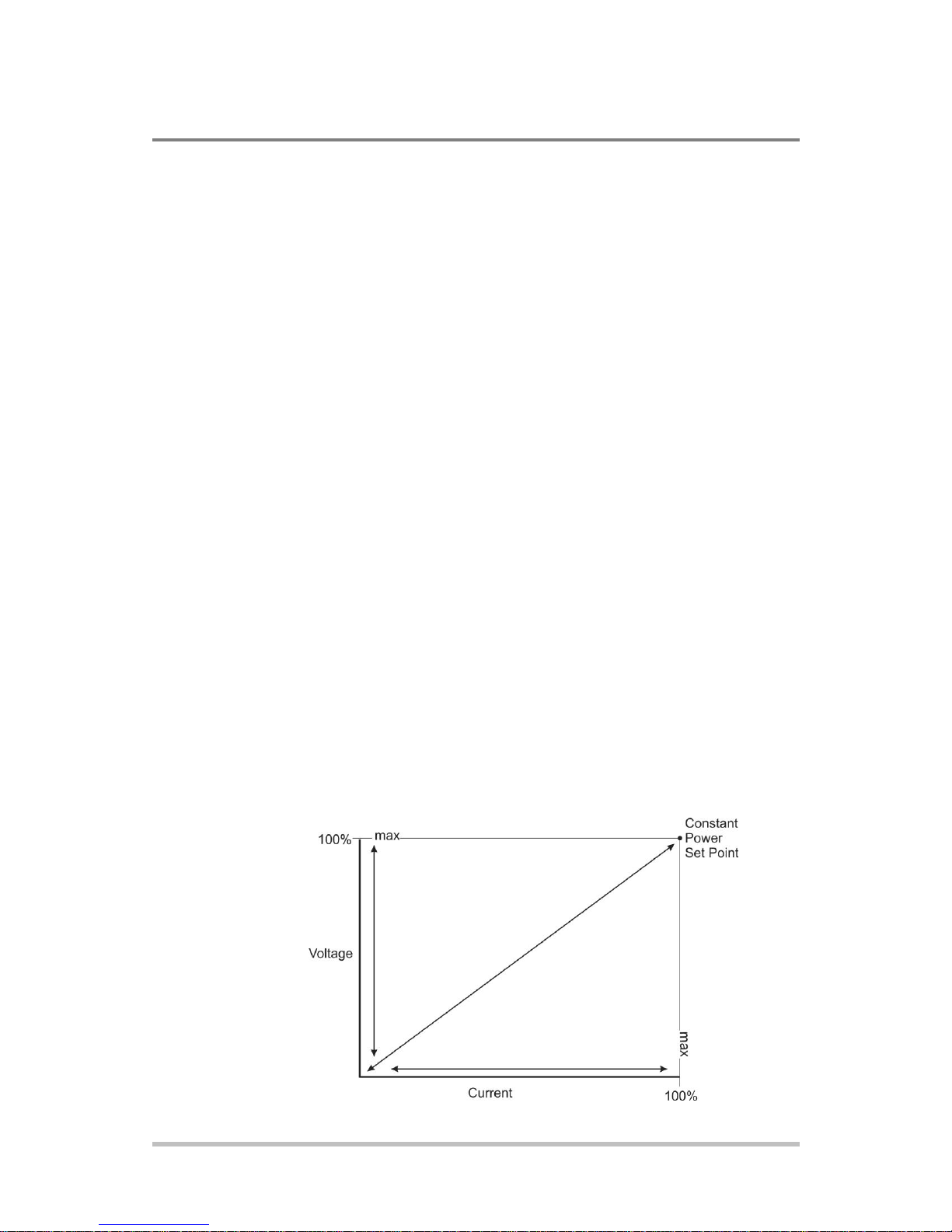
Output disabled
The mode of operation is not determined until the output is enabled. The
CV and CC mode LEDs will not indicate the mode while the output is
disabled.
Local Operation
Constant Voltage (CV) Mode Operation
If the output is enabled and the configured current set point is much
higher than the requirements for the attached load, then the voltage will
rise until it reaches the voltage set point. When the output voltage
reaches the voltage set point, it stops rising. The unit will continue to
operate in CV mode. The load current will still vary to meet any changes
in required load current draw resulting from a change in the attached
load.
Constant Current (CC) Mode Operation
If the output is enabled, the voltage and current start to rise. At this time
the unit is operating in CV mode (default operational mode). As the load
current drawn reaches the value of the output current setting, the unit
will switch to CC mode and not allow any additional current to be drawn
above the value of I
voltage will still vary to meet any changes in required output voltage
resulting from a change in the attached load.
SET
. The unit is now operating in CC mode. The
Constant Power (CP) Mode Operation (version 2.21 and higher)
If the output is enabled, the voltage and current start to rise. The unit
will continue to increase the current until one of thefollowing occurs:
The programmable power set point has been reached.
The voltage set point has been reached, in which case the unit will
regulate the voltage in order to maintain the voltage set point.
The current set point has been reached, in which case the unit will
regulate the current in order to maintain the current set point.
3-12 M370430-01 Rev F
Page 59

3
Load current (V)
Load current (A)
Iset
CV mode
Crossover point
CV mode
Vset
Load current
Load voltage
Load resistance (Ω
Automatic Mode Crossover
Mode crossover occurs when the unit makes the switch between
operating modes. Crossover can occur from CV to CC or vice versa,
depending on how the attached load resistance changes. Figure 3-3
shows the relationships between the variables.
For example, if the unit was initially operating in CV mode with the
output voltage at the voltage set point and the load current below the
I
and the attached load resistance began to decrease, the current
SET
would rise to meet this change in the load. The load current will increase
in proportion to the decrease in the load resistance until the load current
drawn reaches the current set point. At this point further decreases in
load resistance (increased load current requirements) will cause the unit
to cross over into CC mode where the output voltage will vary with
changing load resistance and the load current will remain at the I
value.
The reverse operating mode change can also occur if the load resistance
is increased to the point that the required load current drops below the
I
value. At that point the power supply would crossover to CV mode
SET
and the load current would be free to vary as the load resistance
changed.
Local Operation
SET
Figure 3-3 Operating Modes
M370430-01 Rev F 3-13
Page 60

Important: If you can't get the set point to the desired level, you may need to
change the set points for OVP.
Important: The control circuits have been designed to allow you to set the
output voltage up to 105% over the model-rated maximum value. The power
supply will operate within these extended ranges, but full performance to
specification is not guaranteed.
Quick Tip Remote
operation uses these
SCPI commands. See
page 5-1.
The SCPI command (s) for these instructions are:
[[:]SOURce[<channel>]]:VOLTage[:LEVEl][:IMMediate]
[:AMPLitude]
Important: The maximum and minimum setting values of the output voltage
are limited by the Over Voltage Protection and Under Voltage Protection
settings.
Local Operation
To set the voltage set point (V
SET
):
1. Turn the 9-position mode control to the VOLTS position or
press the rotary Adjust/Enter control if the 9-position mode
control is already at the VOLTS position.
The voltage set point is blinking in the output voltage display. The
output current will be displayed in the output current display.
2. Set the desired voltage value using the rotary Adjust/Enter
control.
3. Press the rotary Adjust/Enter control to transition to Fine
Adjust mode.
The set point will blink faster to indicate fine adjust tracking mode.
4. Set the desired voltage value using the rotary Adjust/Enter
control.
5. Once the desired value has been set, press the rotary
Adjust/Enter control to commit the setting.
To set the current set point (I
SET
:
)
1. Turn the 9-position mode control to the AMPS position or
press the rotary Adjust/Enter control if the 9-position mode
control is already at the AMPS position.
The voltage set point is blinking in the output voltage display. The
output current will be displayed in the output current display.
2. Set the desired current value using the rotary Adjust/Enter
control.
3. Press the rotary Adjust/Enter control to transition to Fine
Adjust mode.
The set point blinks faster to indicate fine adjust tracking mode.
3-14 M370430-01 Rev F
Page 61

3
Important: The control circuits have been designed so that output current can
be set up to 105% over the model-rated maximum values. The power supply
will operate within these extended ranges, but full performance to specification
is not guaranteed.
Local Operation
4. Set the desired current value using the rotary Adjust/Enter
control.
5. Once the desired value has been set, press the rotary
Adjust/Enter control to commit the setting.
The SCPI command (s) for these instructions are:
[[:]SOURce[<channel>]]:CURRent[:LEVEl][:IMMediate]
[:AMPLitude]
M370430-01 Rev F 3-15
Page 62

Local Control Configuration
Additional References
Use the front panel controls to
adjust the output voltage and
current set point settings.
See Chapter 3, “Local Operation” for front
panel operation. See Chapter 4, “Analog
Programming (APG) and Isolated Analog
Programming (ISOL)” for analog
programming procedures.
The OVP set point is adjusted at
the front panel to 105% above
the maximum rated output
voltage.
See “Using Over Voltage Protection (OVP)”
on page 3-27 for the adjustment procedure.
Important: The main output will not turn on if the shutdown function is
activated. See “Using the External Shutdown Function” on page 3-32.
Quick Tip Remote
Operation uses these
commands. See page
5-1.
The SCPI command (s) for these instructions are:
[:]OUTPut[<channel>][:POWer][:STATe]
Local Operation
Shipped Configuration (Local Operation)
The power supply is configured for local operation at the factory. See
Table 3-3 for a summary of this configuration. For more information on
default settings, see Table 3-9 on page 3-42.
Table 3-3 Shipped Configuration
Enabling the Output
Enabling the output on will also turn off the ALARM LED if the
ALARM LED has been latched on due to an alarm triggering and
automatically clearing. See “Alarms and Errors” on page 3-20.
To enable the output power:
Press the OUTPUT ENABLE Main button on the front panel or
enter the SCPI command.
The OUTPUT ENABLE Main button will illuminate.
To disable the output power:
Press the OUTPUT ENABLE Main button when the OUTPUT
ENABLE Main button is illuminated.
The output will be disabled and the LEDs will not be illuminated.
3-16 M370430-01 Rev F
Page 63

3
Important: The auxiliary output will not be enabled if the external
AUX_ON_OFF signal line is being used to disable the auxiliary outputs. See
“AUX Output and Isolated Analog Programming (ISOL) Connector” on page
4-20.
Enabling the Auxiliary Output
To enable on the auxiliary output:
Press the OUTPUT ENABLE Aux button on the front panel.
The OUTPUT ENABLE Aux button will illuminate.
To disable the auxiliary output:
Press the OUTPUT ENABLE Aux button on the front panel again.
The OUTPUT ENABLE Aux button will not be illuminated.
If the auxiliary output is activated, +5 V on J3.9 (+AUX1) and +15
V on J3.11 (AUX2) will be present with respect to Pin J3.2 or Pin
J3.6 (COM ISOLATED). (See also “AUX Output and Isolated
Analog Programming (ISOL) Connector” on page 4-20 for more
details.)
Local Operation
The SCPI command (s) for these instructions are:
[:]OUTPut[<channel>]:AUXiliary[:STATe]
Output Auto Start Mode (Auto Restart)
The Auto Start mode establishes the state of the output of the power
supply after recovery from a complete power cycle (all front panel
LEDs are not illuminated).
If Auto Start mode is set to On, the power supply output will return to its
previous value when the power supply is powered up again.
If Auto Start mode is set to Off, the power supply output will remain off
after the power supply is powered up again.
To change the Auto Start mode:
1. Press and hold the OUTPUT ENABLE Main button for 1
second. or is displayed.
2. Switch the Auto Start mode.
The SCPI command (s) for these instructions are:
[:]OUTPut[<channel>][:POWer][:STATe]:PowerON[:STATe]
M370430-01 Rev F 3-17
Page 64

Local Operation
Auxiliary Auto Start Mode
The Auxiliary Auto Start mode determines the state of the auxiliary
output after a complete power cycle (all front panel LEDS are not
illuminated). With Auxiliary Auto Start mode turned to On, the
auxiliary output will be activated after the power supply is powered up
again.
To define the Auxiliary Auto Start mode:
1. Press and hold the OUTPUT ENABLE Aux button for 1
second. or is displayed.
2. To change to status to On or Off, press the OUTPUT
ENABLE Aux button.
The SCPI command (s) for these instructions are:
[:]OUTPut[<channel>]:AUXiliary:PowerON[:STATe]
Constant Power Mode (version 2.21 and higher)
In Constant Power Mode the power supply will continually adjust the
current levels to maintain a constant power set point. This mode is
intended primarily for loads with response time greater than
approximately 100ms. In order to provide additional protection for the
load, voltage and current limits may be set while in the constant power
mode. If the unit cannot regulate to the Constant Power setting due to
load conditions, it will regulate at either the voltage or the current limit
depending on the load demand.
Example, CP Mode:
Constant Power set 500W
Voltage limit 61V
Current limit 20A
To activate Constant Power mode and set the value:
3. Turn the 9-position mode control to the FLD position or press
the rotary Adjust/Enter control if the 9-position mode control
is already at the FLD position.
4. Turn the rotary Adjust/Enter control until “CP” is displayed.
5. Press the rotary Adjust/Enter control.
6. Turn the Adjust/Enter control to the desired set point.
7. Press the rotary Adjust/Enter control
8. Turn the Adjust/Enter control control for fine adjustment.
3-18 M370430-01 Rev F
Page 65

3
Local Operation
9. Press the rotary Adjust/Enter control to commit the Constant
Power operation.
To disable Constant Power operation:
1. Turn the 9-position mode control to the FLD position or press
the rotary Adjust/Enter control if the 9-position mode control
is already at the FLD position.
2. “FLD” is displayed on the output voltage display and the
output current display shows the Constant Power mode “CP”.
3. Turn the rotary Adjust/Enter control until “NONE” is
displayed in the output current display.
4. Press the rotary Adjust/Enter control to commit the setting
once the desiredvalue has been set.
The SCPI command (s) for these instructions are:
[:]SOURce[<channel>]:POWer:MODe[:STATe]
[:]SOURce[<channel>]:POWer:LEVel
M370430-01 Rev F 3-19
Page 66

Alarm
Precedence
Output
Latch
Maskable
Display
AC Fail
1 (Highest)
Yes
No
Over Temperature Protection (OTP)
2
Yes
No
OtP
Over Temperature Protection (OTP) Slave
(1700 Watt only
3
Yes
Yes
OtP
Fan 4 No
Yes
Fan Slave (1700 Watt only)
5
No
Yes
Interlock
6
No
No
In Loc
Over Voltage Protection (OVP)
7
Always
No Over Current Protection (OCP)
8
Always
No Foldback
9
Yes
Yes External Shutdown
10
No
Yes Under Voltage Protection (UVP)
11 (Lowest)
No
Yes
Current Loop Protection
12 (Lowest)
Loop Pro
Flash Checksum Failure1
N/A
N/A
N/A
Local Operation
Alarms and Errors
Several conditions can cause alarms in the XG. Some conditions are:
From user configurable features.
Controlled in hardware and will trigger regardless of
configuration.
All alarms, with the exception of the Fan alarm, will result in the output
of the power supply being disabled. The Fan alarm does not affect the
output.
When an alarm is triggered, the appropriate alarm message will begin
blinking on the display and the Alarm LED will be illuminated.It is
possible that more than one alarm will trigger at the same time. When
this occurs, the alarm with the highest precedence will blink on the
display. Table 3-4 lists the precedence of alarms. If the alarm is cleared
and the event which caused the alarm has not been corrected, then the
alarm may trigger again immediately. Fix the reason for the alarm
before you clear it.
Table 3-4 Alarm Order of Precedence
1. The Flash Checksum Failure alarms are an exception as they can only occur during boot up or
recalling a user setting slot. If a checksum error is detected when recalling a user slot, no modification of settings will occur, and an error will be pushed to the SCPI error queue. If a checksum
occurs at boot-up, then this checksum error can be cleared by doing a soft reset or by power cycling
the unit.
3-20 M370430-01 Rev F
Page 67

3
Important: When an alarm is cleared by using this method, only the current
highest precedence alarm is cleared. If another alarm has occurred, then this
alarm will now become the highest precedence alarm and will begin blinking on
the display.
Clearing Alarms
Clearing Triggered and Manual Alarms
To clear a triggered alarm, use one of the following methods:
Turn the power supply Off and then On.
Press and hold the rotary Adjust/Enter control for 3 seconds.
To clear a manual alarm:
1. Press and hold the rotary Adjust/Enter control for 3 seconds.
The message will be displayed on the front panel for a
few seconds.
2. Repeat the alarm clearing until you have cleared all alarms.
Local Operation
Clearing a Flash Failure Alarm
The Flash Failure alarm is the only exception for clearing alarms. If a
flash failure occurs at boot time, it can only be cleared by a soft reset key
combination press (see “Resetting the Power Supply” on page 3-42) or
by power cycling the unit. If a checksum error is detected when recalling
a user slot, no modification of settings will occur, and an error will be
pushed to the SCPI error queue. The alarm will clear after a duration per
the currently configured front panel timeout setting.
To clear a triggered alarm, use one of the following methods:
Turn the power supply Off and then On.
For failures that occur during a recall of user memory settings, wait
the duration of the currently configured front panel timeout.
Press and hold the reset key combination (Flash Fail ONLY). See
“Resetting the Power Supply” on page 3-42.
The SCPI command (s) for these instructions are:
[:]OUTPut[<channel>]:PROTection:CLEar
M370430-01 Rev F 3-21
Page 68

Local Operation
Clearing Automatic Alarms
Some alarms will clear automatically when the condition that caused the
alarm is no longer present. When an alarm automatically clears, the
output voltage and current displays will return to normal, but the
ALARM LED will remain illuminated to indicate that an alarm has
occurred. If an automatic alarm is triggered, the normal alarm clearing
procedure still applies.
To clear the ALARM LED after an automatic alarm has cleared,
use one of the following methods:
Send the SCPI Clear Alarm command.
Press the OUTPUT ENABLE Main button to reenable the output.
The ALARM LED will no longer be illuminated.
For example, if one of the fans in the XG was temporarily blocked,
causing a Fan alarm, then the blockage was cleared and the fans
restarted, the alarm would clear. The output voltage and current displays
would be in normal mode, but the ALARM LED would be illuminated.
See “Front Panel ALARM LED” on page 3-22 for information on other
events that affect the ALARM LED.
Alarms status is tracked in the SCPI status registers. For more details on
how and where the alarms are tracked, see “Standard SCPI Register
Structure” on page 5-38.
Front Panel ALARM LED
The Alarm LED will illuminate due to one or more of the following
events occurring:
OTP has been tripped.
A fan has stopped.
OVP has tripped.
OCP has tripped.
UVP has tripped
Interlock is open circuit.
AC power falls out of range.
Foldback has tripped.
Persistent storage checksum is wrong (Flash Fail alarm).
Internal malfunction of power supply.
Any alarm has tripped and been cleared automatically.
3-22 M370430-01 Rev F
Page 69

3
Alarm
Bit Position
Value
Over Temperature Protection (OTP)
2
2
Over Temperature Protection (OTP) Slave
(1700W only)
3
4
Fan 3 8
Foldback
8
256
External Shutdown
9
512
Under Voltage Protection (UVP)
10
1024
Alarm Masking
Local Operation
The alarm LED will remain illuminated until the alarm is manually
cleared (see “Clearing Triggered and Manual Alarms” on page 3-21) or
by turning the main output on if the alarm has automatically been
cleared.
It is possible to completely disable some alarms through the use of the
alarm mask. If an alarm is masked then this masking will prevent it from
registering in the SCPI conditions registers as well as not triggering the
alarm. The alarms that can be masked are identified in Table 3-4 on page
3-20. Setting the bit position (1) of an alarm will result in the alarm
being enabled. Clearing the bit position (0) of an alarm will result in the
alarm being masked/disabled.
For Example:
If you wanted to enable the OTP, Foldback and UVP alarms, you would
take the foldback value of 256 and the UVP value of 1024 to get a mask
of 1280. This is the value you would send with the SCPI command.
Control of the alarm mask is only available using the SCPI command.
The SCPI command (s) for these instructions are:
[:]SYSTem[<channel>]:PROTection:MASK
The mask command takes a single parameter made up of the sum of the
values for the alarms that are to be masked. See Table 3-5 for the alarm
values associated with each maskable alarm.
Table 3-5 Alarm Mask Bit Positions
The SCPI command (s) for these instructions are:
[:]SYSTem[<channel>]:PROTection:MASK
M370430-01 Rev F 3-23
Page 70

Alarm
Bit
Position
Value
AC Fail
0
1
Over Temperature Protection (OTP)
1
2
Over Temperature Protection (OTP) Slave
(1700 Watt only)
3
4
Foldback
8
256
Local Operation
Alarm Output Latching
When an alarm is triggered, the output will be disabled with the
exception of the Fan alarm. When an alarm is cleared, the alarm output
latch determines if the output should be re-enabled to the state before the
alarm occurred or if the output should remain in the off state.
Where setting the bit position (1) of an alarm latch will result in output
latching to the off state when the alarm is cleared and if cleared (0)
output will be re-enabled to the state before the alarm triggered.
To define the values for the bit position you determine which alarms you
want to latch. Read the value for this bit position from Table 3-6 and
sum them together. The result is the alarm last mask, which you should
send with the SCPI command.
For Example:
If you wanted to enable latching for OTP and Foldback you would take
the OTP value of 2 and add it to the foldback value of 256 to get a mask
of 258. This is the value you would send with the SCPI command.
The output latches are accessible through the SCPI command.
The SCPI command (s) for these instructions are:
[:]SYSTem[<channel>]:PROTection:LATCh
The latch command take a single decimal parameter made up of the sum
of the values for the alarms to determine if they are to be latched in the
off state on clearing. See Table 3-6 for the values associated with each
latchable alarm.
Table 3-6 Alarm Latch Bit Positions
3-24 M370430-01 Rev F
Page 71

3
Setting Foldback Mode
Foldback mode is used to disable the output when a transition is made
between the operating modes. The power supply will turn off/disable the
output and lock in foldback mode after a specified delay if the power
supply transitions into CV mode or into CC mode, depending on the
foldback mode settings. This feature is particularly useful for protecting
current or voltage sensitive loads. Foldback can be set to trigger a switch
when transitioning from CV to CC mode or from CC to CV mode.
To set the foldback protection and foldback delay time:
1. Turn the 9-position mode control to the FLD position or press
the rotary Adjust/Enter control if the 9-position mode control
is already at the FLD position.
2. Select the type of crossover that will cause foldback to trigger
by using the rotary Adjust/Enter control.
If the mode selected is CC or CV mode, the foldback delay timer
will start on a transition into the selected mode. If the mode
selected is none, foldback is not enabled.
Local Operation
3. Press the rotary Adjust/Enter control when the desired mode
has been selected.
The FLD LED will illuminate and will be displayed in the
output voltage display.
4. Adjust the desired delay time using the rotary Adjust/Enter
control.
The range can be set from 0.50 seconds to a maximum of 50
seconds. The step size is in increments of 0.05 seconds when
setting from 0.50 to 5 seconds and then in 1 second increments
from 5 seconds to 50 seconds.
5. Once the desired foldback delay time has been selected, press
the rotary Adjust/Enter control to commit the foldback delay
setting.
To disable foldback protection:
1. Turn the 9-position mode control to the FLD position or press
the rotary Adjust/Enter control if the control knob is already
at the FLD position.
2. is displayed on the output voltage display and the output
current display shows the current foldback trigger mode.
3. Turn the rotary Adjust/Enter control until is displayed
in the output current display.
M370430-01 Rev F 3-25
Page 72

Important: If you set foldback while the output is enabled and the trigger you
select is the same as the current operating mode, the foldback timer will begin
counting immediately after the delay time has been set.
Local Operation
4. Press the rotary Adjust/Enter control to commit the setting
once the desired value has been set.
5. The green FLD LED will turn off and the display will return
to the normal display mode.
The SCPI command (s) for these instructions are:
[:]OUTPut[<channel>]:PROTection:FOLDback[:MODE]
[:]OUTPut[<channel>]:PROTection:FOLDback:LATCh
Resetting Activated Foldback Protection
To reset activated and latched foldback protection, press and hold the
rotary Adjust/Enter control for approximately 3 seconds.
The SCPI command (s) for these instructions are:
[:]OUTPut[<channel>]:PROTection:CLEar
3-26 M370430-01 Rev F
Page 73

3
Using Over Voltage Protection (OVP)
The OVP circuit protects the load in the event of an analog
programming error, an incorrect voltage control adjustment, or a
power supply failure. The OVP circuit monitors the output voltage
at the output of the power supply and will disable the output
whenever a preset voltage set point is exceeded. You can set the
preset voltage trip point by using the 9-position mode control on
the front panel or via one of the remote programming interfaces.
To prevent accidental tripping of the OVP while setting up, the
firmware will prevent the OVP set point from being less than
105% of the voltage set point when in local set point control mode.
When the XG is in VAP mode for defining voltage set point the set
point limitation will be based on the VAP input signal level. The
user should note it is possible to trip OVP in this mode if the OVP
is configured when the analog programming source is off.
When the user attempts to configure an OVP setpoint that is less
than 105% of the voltage set point via the front panel the set point
will stop allowing the value to decrement. If the user attempts to
configure an OVP set point that is less than 105% of the voltage set
point via SCPI a -221, “settings conflict error” will be pushed onto
the error queue.
Local Operation
M370430-01 Rev F 3-27
Page 74

Important: The OVP range is variable from V
SET
+5% to V
MAX
+25%.
Local Operation
Defining the OVP Set Point
To define the OVP set point:
1. Turn the power supply On.
Ensure the voltage is lower than the desired set point.
2. Set the output to the desired voltage.
OVP can be set without setting desired output voltage first.
3. Turn the 9-position mode control to the PRT position. PrO
OVP is displayed.
4. Press the rotary Adjust/Enter control.
5. Turn the rotary Adjust/Enter control to set the upper limit
protection. See “Coarse and Fine Adjustment Modes” on
page 3-3.
6. Once the desired value has been set, press the rotary
Adjust/Enter control to commit the setting.
The SCPI command (s) for these instructions are:
[[:]SOURce[<channel>]]:VOLTage:PROTection[:OVERvoltage]
[:LEVel]
If the output is between OVP
and -5%, an OVP warning message
set
is possible when in APG mode.
3-28 M370430-01 Rev F
Page 75

3
Important: UVP will not be active for voltage set points that are less than 1%
of model voltage.
Important: The UVP range is variable from 0 volts to OVP
SET
-10%.
Using Under Voltage Protection (UVP)
The UVP prevents voltage settings below a set value. The UVP lets you
create a voltage window of operation when used in conjunction with the
OVP setting. The UVP range is variable from 0 V to OVP
The UVP is a protection that becomes active after the output is enabled
and a period of time has passed to allow the output to reach its set point
value before the UVP protection begins monitoring. As with OVP if the
voltage set point is determined by analog control (VAP) and the voltage
strays to within 5% of the UVP set point then UVP Safe will trigger to
warn the user that they are about to trigger the UVP alarm.
The period of time before the UVP monitoring is active after the output
is enabled is determined by the rise-time delay for the model as listed in
Table C-2, “Remote Operation Programming” on page C-8 on the row
called Up-prog Response Time, 0 - Vmax. Since the rise time is based
on a purely resistive load the user should be aware that UVP triggering
might be possible in capacitive or rectifier loads due to the rise time
being longer. In these cases it is recommended that the user mask the
UVP alarm until the rise time has elapsed and then unmask the alarm to
allow UVP protection to be enabled during operation.
Local Operation
-10%.
SET
Defining the UVP Set Point
To define the UVP set point:
1. Turn the power supply On.
2. Set the output to the desired voltage.
3. Turn the 9-position mode control to the PRT position.
is displayed.
4. Turn the rotary Adjust/Enter control until is
displayed.
5. Press the rotary Adjust/Enter control to select the UVP for
setting up.
6. Set up the lower limit protection using the rotary Adjust/Enter
control.
7. Once the desired value has been set, press the rotary
Adjust/Enter control to commit the setting.
See “Coarse and Fine Adjustment Modes” on page 3-3.
The SCPI command (s) for these instructions are:
[[:]SOURce[<channel>]]:VOLTage:PROTection:UNDer[:LEVel]
M370430-01 Rev F 3-29
Page 76

Local Operation
Over Current Protection (OCP)
The OCP alarm is a firmware alarm that is only configurable using the
SCPI interface. The OCP triggers if the output current exceeds the OCP
set point. Because the OCP alarm is a firmware based alarm it has a
latency before detection of the condition can occur. The user should be
aware of this latency and take this into consideration when relying on
OCP to protect a sensitive load. The maximum period for detecting an
OCP condition is 300 ms.
OCP is fixed at 110% of rated current.
3-30 M370430-01 Rev F
Page 77

3
Local Operation
Using Over Temperature Protection Lock (OTP)
The OTP lock protects the power supply in the event of an over
temperature alarm. This alarm could be caused by ventilation restriction
or overheating due to fan failure.
Two modes are available:
Auto recovery (OTP OFF) where the power supply turns on again
after cooling down.
Latch mode (OTP ON) where you will need to reset the unit by
turning the front panel power switch to Off and then On again.
If the OTP is activated, the main output will turn off and (over
temperature protection) will blink on the display. The OTP alarm is an
alarm that will auto recover when the temperature falls back into normal
bounds.
Defining the OTP Mode
To define the OTP lock:
1. Turn the 9-position mode control to the PRT position. PrO
OUP is displayed.
2. Turn the rotary Adjust/Enter control until is
displayed.
3. Press the rotary Adjust/Enter control to display
4. Turn the rotary Adjust/Enter control to change to On or Off.
5. Press the rotary Adjust/Enter control.
The SCPI command (s) for these instructions are:
[:]SYSTem[<channel(s)>]:PROTection:LATCh
Resetting in Latch Mode
To reset the power supply if the OTP alarm is tripped and the OTP mode
is set to On (latching enabled), press and hold the rotary Adjust/Enter
control for approximately 3 seconds.
The SCPI command (s) for these instructions are:
[:]OUTPut[<channel(s)>]:PROTection:CLEar
[:]SYSTem[<channel(s)>]:PROTection:LATCh
.
M370430-01 Rev F 3-31
Page 78

Local Operation
Using the External Shutdown Function
Use the external shutdown function to enable or disable the output of the
power supply via a logic level signal. When the external shutdown is
triggered, the power supply will display SD POL on the output voltage
and current displays. The external shutdown is useful for making
adjustments to either the load or the power supply without shutting off
the power supply or for using the power supply as part of a larger test
system in which digital or analog control is required.
Activating the External Shutdown Function
To activate the external shutdown function, use the AUX output supply
provided on the Analog Programming Connector J3. This input has a
user selectable polarity with logic low input from 0.0V to 1.2V and
logic high from 4.0V to 15V. The control signal for this input must be
capable of sinking 10mA minimum. This input is also compatible with
the use of dry contacts, where a short is logic low and an open is logic
high. The input lines of the shutdown circuit are fully optically isolated.
See page C-8 for specifications.
Once the External Shutdown has been triggered, the display will blink
the .
Controlling the External Shutdown Function
The external shutdown circuit accepts a voltage or dry contact control
(high or low logic level) to enable or disable the power supply output.
Make connections for the signals at the AUX Output and Isolated
Analog Programming Connector on the rear panel. (See “AUX Output
and Isolated Analog Programming (ISOL) Connector” on page 4-20 for
more information.)
To activate the shutdown function:
Connect the control signal source to the Shutdown pin (J3.12) on the
Aux Output and Isolated Analog Programming Connector with the
control circuit ground connected to Isolated Ground pin (J3.6).
The External Shutdown pin is pulled high internally (normally high).
Therefore, if this feature is not used, the polarity should be set to 1 to
avoid false triggering. (See “Defining the Polarity of the External
Shutdown Signal” on page 3-33 for instructions.)
3-32 M370430-01 Rev F
Page 79

3
Important: There is an internal pullup resistor inside the shutdown circuit so
the shutdown polarity should be set to 0 if it is not being used.
Important: While Loop Protection is enabled (ON), the external shutdown
function will be automatically set to low active. When Loop Protection is
disabled (OFF), the external shutdown function will be set to the user’s last
setting.
Local Operation
Defining the Polarity of the External Shutdown Signal
1. Turn the 9-position mode control to the PRT position or press
the rotary Adjust/Enter control if the control knob is already
at the PRT position.
is displayed on the output voltage display.
2. Turn the rotary Adjust/Enter control until is
displayed.
3. Press the rotary Adjust/Enter control to display
(shutdown on logic 0) or (shutdown on logic 1).
4. Press the rotary Adjust/Enter control to commit the desired
polarity setting.
For example: If you set the shutdown logic to 1 ( ) and apply a
logic high (greater than 4 Vdc) to pin J3.12 relative to pin J3.6 on
the ISOL connector, the power supply will shut down. Conversely,
if you set the shutdown logic to 0 ( ), the power supply will
only operate when you have a logic high (greater than 4 Vdc) to pin
J3.2 relative to pin J3.6.
The SCPI command (s) for these instructions are:
[:]OUTPut[<channel>]:POLarity
Loop Protection (version 2.21 and higher)
The Loop Protection feature can be used to enable or disable multiple
units in daisy chain configuration through the AUX Output and Isolated
Analog Programming Connector, J3. Up to four units (example, Units
#1 through #4) can be configured in Loop Protection; if one of the units
is experiencing a fault condition, other units in the same loop will
disable their output simultaneously. This is achieved by connecting Unit
#1’s MAIN_PS_GOOD to Unit #2’s SD (Shutdown Main O/P) and
continues until Unit #4’s MAIN_PS_GOOD is fed to Unit #1’s SD
(Shutdown Main O/P). Common applications include single master
controlling multiple slave units as a system On/Off. In addition, any
fault from either operating unit will cause the system to disable.
The Loop Protection can be enabled or disabled locally using the front
panel 9-position mode control, or remotely using a SCPI command.
M370430-01 Rev F 3-33
Page 80

Local Operation
Setting up Loop Protection
To set up Loop Protection:
With the AC powered OFF, connect the first unit’s pin J13.13 to the
next unit’s J 13.12 on the AUX Output and Isolated Analog
Programming Connector. Do this for up to four units. An example of a
3-unit loop protection is illustrated as follows:
To enable or disable Loop Protection:
1. Turn the 9-position mode control to the PRT position. PRO
OVP is displayed.
2. Turn the rotary Adjust/Enter control until LOOP PRO is
displayed.
3. Press the rotary Adjust control to display LOOP ON or OFF.
4. Press the rotary Adjust control to change the setting to ON or
OFF.
5. Press the rotary Adjust control to accept the change.
The SCPI command (s) for these instructions are:
[:]OUTPut [<channel>]:PROTection:Loop[:STATe]
3-34 M370430-01 Rev F
Page 81

3
Interlock Function
The Interlock function can be used to wire an external shutoff switch
that can be used to enable or disable the power supply output. When the
switch is closed, the power supply will operate normally. If the switch is
opened, the power supply will trigger the interlock alarm. The output
will be disabled, the display will blink , and the ALARM LED
will illuminate. This alarm will automatically clear when the switch
closes again, and the output will automatically be restored to its
pre-alarm state (either enabled or disabled). The interlock function can
only be enabled or disabled (defined) using a SCPI command (cannot be
masked or latched through the alarm protection mechanisms.). Common
applications include an emergency shutoff switch or a door switch.
Connect the switch between pins J3.14 and J3.15 on the AUX Output
and Isolated Analog Programming Connector.
Defining the Interlock Mode
Local Operation
The Interlock mode is controlled via SCPI commands. There is no front
panel access for enabling or disabling the Interlock functionality. See
“Interlock Enable/Disable” on page 5-69.
The SCPI command for setting the Interlock mode to On or Off is:
[:]SENSe[<channel>]:PROTection:INTerlock[:STATe]
Output Protection
The output voltage and the output current can be programmed (preset) to
automatically start at zero Volts and zero Amps upon power-up and
upon output enable. Also, each can be reprogrammed to disable the
autotmatic reset to zero.
Note: With the M10 Option, the power supply voltage output is
preset to 0 Volts.
Programming Voltage Output Preset
To Enable/Disable automatic reset to 0 Volts:
1. Turn the rotary Adjust/Enter control to PRT and press.
2. Turn again until is displayed.
3. Press to display .
M370430-01 Rev F 3-35
Page 82

Local Operation
4. Turn to display or .
5. Press to commit the selected setting.
Important: This single front panel operation affects both power on and
output enable. However, when using SCPI, there is a separate command
for each.
The SCPI command to query or enable/disable the 0 Voltage
Output Preset at power-on is:
[:]SYSTem[<channel>]:PON:VOLTage {?|ON|OFF}
The SCPI command to query or enable/disable the 0 Voltage
Output Preset upon output enable is:
[:]SYSTem[<channel>] :PON:ENAble:VOLTage {? |ON|OFF}
Programming Current Output Preset
To Enable/Disable automatic reset to 0 Amps:
1. Turn the rotary Adjust/Enter control to PRT and press.
2. Turn again until is displayed.
3. Press to display .
4. Turn to display or .
5. Press to commit the selected setting.
Important: This single front panel operation affects both power on and
output enable. However, when using SCPI, there is a separate command
for each.
The SCPI command to query or enable/disable the 0 Current
Output Preset at power-on is:
[:]SYSTem[<channel>]:PON:CURRent {?|ON|OFF}
The SCPI command to query or enable/disable the 0 Current
Output Preset upon output enable is:
[:]SYSTem[<channel>] :PON:ENAble:CURRent {? |ON|OFF}
3-36 M370430-01 Rev F
Page 83

3
Power On Status Signal
Power On Status signal indicates a fault condition in the power supply.
Power On Status signal is a TTL output signal at Pin J2.13 with
reference to COM ISOLATED (Pin J2.2 or Pin J2.6).
During normal operation, the Power On Status signal will be high. If the
output is disabled for any reason, the Power On Status signal will go
low.
The following conditions will set the Power On Status to a low level:
AC fail
Current Loop Protection
Over Voltage Protection (OVP)
Under Voltage Protection (UVP)
Over Current Protection (OCP)
Over Temperature Protection (OTP)
Local Operation
Foldback Protection
Interlock
Output Off
Shutdown activated (rear panel shutdown).
Internal hardware malfunction Fan failure
Hardware Malfunction Alarms
The power supply will turn off the output. An error message will be
displayed in the event that:
OVP trips
Voltage deviation in CV mode reaches more than ±5% from the set
Current deviation in CC mode reaches more than ±5% from the set
__________________________
1. These two forms of hardware malfunction are only monitored in the
corresponding APG mode.
level.
level.1
1
M370430-01 Rev F 3-37
Page 84

Voltage Setpoint
Current Setpoint
Voltage Output Protection
Current Output Protection
Over Voltage Protection (OVP)
Under Voltage Protection (UVP)
Over Temperature Protection (OTP)
Autostart OUTPUT ENABLE Main
Autostart OUTPUT ENABLE Aux
Foldback Mode
Foldback Delay
Shutdown Logic
Voltage Analog Programming (VAP) Mode
Voltage Analog Programming (VAP) Level
Current Analog Programming (CAP) Mode
Current Analog Programming (CAP) Level
Remote Programming Interface
Local Lock
PSU (Power Supply) Address
Data Rate (BPS)
Alarm Latches
Front Panel Timeout
Constant Power Mode*
Constant Power Level*
Loop Protection Enable
Line Drop Mode Settings
* version 2.21 and higher
Local Operation
Current Configuration Memory Settings
The power supply will save the unit settings at the time of power down.
These settings will be loaded when the power is restored to the unit or
the power supply is powered up again. Table 3-7 lists the settings that
are saved and recalled on a power cycle event.
Table 3-7 Power Cycle Saved/Recalled Settings
3-38 M370430-01 Rev F
Page 85

3
Voltage Setpoint
Current Setpoint
Voltage Output Protection
Current Output Protection
Over Voltage Protection (OVP)
Over Temperature Protection (OTP)
Autostart OUTPUT ENABLE Main
Autostart OUTPUT ENABLE Aux
Foldback Mode
Foldback Delay
Shutdown Logic
Voltage Analog Programming (VAP) Mode
Voltage Analog Programming (VAP) Level
Current Analog Programming (CAP) Mode
Current Analog Programming (CAP) Level
Current Sharing Mode
Alarm Latches
Front Panel Timeout
User Setting Memory Locations
There are three user setting memory locations available for storing
frequently used configurations. These user setting memory locations
help to facilitate multiple users of an XG power supply who have
different setups or when multiple loads are used that have different
requirements. Table 3-8 lists the values that are stored in each user
setting memory location.
Table 3-8 User Accessible Saved/Recalled Settings Voltage Setpoint
Local Operation
M370430-01 Rev F 3-39
Page 86

Local Operation
Saving User Setting Memory Locations
To save user setting memory locations:
1. Turn the 9-position mode control to the SAV position.
is displayed on the output voltage display with a number
indicating a preset position which is displayed on the output current
display.
2. Turn the rotary Adjust/Enter control to select a preset position
from 1 to 3.
3. Press the rotary Adjust/Enter control.
done is displayed on the output voltage display.
4. The setting has now been saved to the selected user setting
memory location.
The SCPI command (s) for these instructions are:
*SAV <setting_location>
or
[:]SYSTem[<channel>]:SAVE <setting_location>
Recalling User Setting Memory Locations
This feature recalls settings that were previously saved.
To load user setting memory locations:
1. Turn the 9-position mode control to the RCL position.
is displayed on the output voltage display with a number
indicating a preset position on the output current display.
2. Turn the rotary Adjust/Enter control to select a preset position
from 1 to 3.
3. Press the rotary Adjust/Enter control.
is displayed on the output voltage display.
The settings in the selected user setting memory locations have
now been applied to the power supply.
The SCPI command (s) for these instructions are:
*RCL <setting_location>
or
[:]SYSTem[<channel>]:RECall <setting_location>
Three user setting memory locations are available and one user
setting memory location is saved automatically before AC power
shutdown. This user setting memory location will be loaded after
AC power is restored.
3-40 M370430-01 Rev F
Page 87

3
Local Lockout
Local lockout is a feature that allows the front panel to be locked so that
accidental button presses are ignored. This feature is often used to
lockout the front panel when you are controlling the power supply from
a remote location. When in local lockout mode, the front panel will
display Loc whenever a button is pressed or a knob is turned.
Enabling Local Lockout
To enable local lockout:
1. Turn the 9-position mode control to the PGM position or
press the rotary Adjust/Enter control if the control knob is
already at the PGM position.
The display will show in the output voltage display and the
selected remote interface in the output current display.
2. Turn the rotary Adjust/Enter control until the display shows
3. Press the rotary Adjust/Enter control.
4. Turn the rotary Adjust/Enter control until the display shows
5. Press the rotary Adjust/Enter control. Local lockout has been
enabled.
Local Operation
.
.
The SCPI command (s) for these instructions are:
[:]SYSTem:REMote:STATe
Disabling Local Lockout
To disable local lockout:
1. Turn the 9-position mode control to the PGM position or
press the rotary Adjust/Enter control if the control knob is
already at the PGM position.
The display will show in the output voltage display and the
selected remote interface in the output current display.
2. Turn the rotary Adjust/Enter control until the display shows
.
3. Press the rotary Adjust/Enter control.
Local lockout will be disabled after power-cycling the power
supply.
The SCPI command (s) for these instructions are:
[:]SYSTem[<channel(s)>]:REMote:STATe
M370430-01 Rev F 3-41
Page 88

The reset is used to clear the parameters to the factory default values.
Soft Reset
The soft reset is used to set the parameters (see Table 3-9) to the default
values, but it does not reset the calibration constants
Parameter
Setting
Address
1
Data rate (Kbps)
9.6
Communication mode
RS-232
Vout setting
0 V
Iout setting
0 A
Output
Off
AUX Out
Off
Trigger
Off
Ext. On/Off Polarity
Negative
Auto start mode
Off
AUX Auto start mode
Off
OVP
Maximum
UVP
0 V
Foldback trigger
None
Foldback delay
0.5 s
Current Share Mode
Controller
Local Operation
Resetting the Power Supply
To perform a soft reset:
1. Turn the power supply to Off then On.
When the unit is powering on, is displayed on the
output voltage and current displays.
2. Press the key combination of both OUTPUT ENABLE Main
button and OUTPUT ENABLE Aux button and hold
continuously for 3 seconds in order to execute.
If the flash fail alarm triggers, it is also possible to reset the power
supply. The front panel should display .
3. Once a reset has been triggered, the output voltage display
shows for 1 second.
The model number will be displayed for 1 second and then return
to normal mode.
After executing a reset, the power supply's settings are restored to the
default settings but retain the calibration data. Table 3-9 lists the default
settings.
Table 3-9 Power Supply Default Settings
3-42 M370430-01 Rev F
Page 89

3
Parameter
Setting
Alarm Output Latches
263 (0 x 107, all latches enabled)
Alarms Mask
2047 (0 x 7FF, all enabled)
Interlock
Disabled
Voltage Analog Programming
Off
Voltage APG Scale
10 V
Current Analog Programming
Off
Current APG Scale
10 V
Voltage Output Protection
Off
(except M10 Option: always On)
Current Output Protection
Off
(except M10 Option: always On)
Local Operation
M370430-01 Rev F 3-43
Page 90

WARNING: Shock hazard
There is a shock hazard at the load when using a power supply at an output of
greater than 40V or a combined output of greater than 40V. To protect personnel
against accidental contact with hazardous voltages created by a series
connection, ensure that the load, including connections, has no live parts which
are accessible. Also ensure that the insulation rating of the load wiring and
circuitry is greater than or equal to the maximum or combined output voltage of
the power supply.
CAUTION: Equipment damage
Do not connect power supplies from different manufacturers in parallel or in
series.
CAUTION: Equipment damage
The remote programming inputs are internally referenced to the power supply's
negative output. Do not connect remote programming ground lines to the power
supply's positive output.
Local Operation
Using Multiple Power Supplies
You can operate power supplies of the same model with the
outputs in series to obtain increased load voltage or with the
outputs in parallel to obtain increased current, also called current
sharing. Split supply operation gives you two positive outputs, or a
positive and a negative output. See Figure 3-5 on page 3-45. When
using multiple supplies in series or parallel, they will not meet the
single unit specifications in this Manual.
3-44 M370430-01 Rev F
Page 91

3
Power Supply
Power Supply
Common
Load
Local Operation
Figure 3-4 Split Supply Operation
M370430-01 Rev F 3-45
Page 92
CAUTION: Equipment damage
When two power supplies are connected in series, they should be programmed
to the same output voltage to prevent damage to the lower voltage supply at
short circuit condition.
CAUTION: Equipment damage
Use properly rated diodes to protect the power supply from damage while
driving inductive loads..
Local Operation
Configuring Multiple Supplies for Series Operation
A maximum of two power supplies of the same rating can be connected
in series to increase the output voltage.
Load Considerations
INDUCTIVE LOADS:
To prevent damage to the power supply from inductive kickback,
connect a diode (rated at greater than the supply’s output voltage and
current) across the output. Connect the cathode to the positive output
and the anode to return. Where positive load transients, such as back
EMF from a motor may occur, a second diode in series with the output is
recommended to protect the power supply.
BLOCKING and FREE WHEELING DIODES:
The Peak Reverse Voltage ratings should be a minimum of 2-3 times the
power supply maximum output voltage. The Continuous Forward
Current rating should be a minimum of 1.5 times the power supply
maximum output current. Heatsink may be required. There also may be
a need for higher voltage rated parts, dependent on load circuit design
and inductor values.
Connecting to the Load in Local Sensing Mode
Connect the negative (-) output terminal of one power supply to the
positive (+) output terminal of the next power supply. See Figure 3-5 for
a representation of series operation.
3-46 M370430-01 Rev F
Page 93

3
Local Operation
Figure 3-5 Series Operation
M370430-01 Rev F 3-47
Page 94

CAUTION: Equipment damage
Do not connect sense lines through relays.
Local Operation
Connecting to the Load in Remote Sensing Mode
Connect the negative (-) output terminal of one power supply to the
positive (+) output terminal of the next power supply. The more
positive supply's positive sense line should connect to the positive
terminal of the load (or distribution point). Its return sense line
should connect to the connection between the two units at the same
spot as the negative supply's positive sense line. The return sense
line of the negative supply should be connected to the return of the
load. See Figure 3-6.
Figure 3-6 Load Connections in Remote Sensing Mode
3-48 M370430-01 Rev F
Page 95

3
Important: If current sharing is not being used, the unit must be configured as
a controller. Failure to do so will result in unpredictable operation.
Local Operation
Configuring Multiple Supplies for Current Sharing Operation
(APG Method)
Up to four power supplies can be connected in parallel to increase the
output current. One of the units will operate as the master unit and the
remaining units will operate as slave units controlled by the master unit.
The master unit uses the analog programming lines to set the output
voltages and currents of the slave units to match its output.
In remote digital operation, only the master unit can be programmed
remotely while the slave units that are connected remotely will only
provide voltage, current and status readback information.
In APG current sharing topologies, only the master unit can be
programmed using any of the input methods (front panel, remote digital,
or analog programming control). The slave unit(s) voltage and current
output(s) are determined by the master unit through the REF_I input to
each slave unit. The readback using any of the monitoring methods
(front panel display, user monitor lines or SCPI measure commands) of
each unit (master or slave) will provide individual unit status, not
system status.
Setting up the Controller Unit
Set the output voltage of the master unit to the desired voltage. Program
the current set point of the master unit to the desired load current set
point divided by the number of parallel units. During operation, the
master unit operates in Constant Voltage mode, regulating the load
voltage at the programmed output voltage. Send the Current share SCPI
command or use the following instructions to program front panel
current share setup:
1. With the 9-position mode control at the PGM position, press
the rotary Adjust/Enter control.
is displayed on the output voltage display.
2. Turn the rotary Adjust/Enter control to select and
press the Adjust/Enter control.
is displayed on the output voltage display.
3. Turn the rotary Adjust/Enter control to select in the
output current display.
M370430-01 Rev F 3-49
Page 96

Important: The slave unit discussed here is not the same as the remote
interface slave described in chapter 5.
Local Operation
4. Press the rotary Adjust/Enter control to commit the setting.
The SCPI command (s) for these instructions are:
[[:]SOURce[<channel>]]:COMBine:CSHare[:MODE]
Setting up the Slave Units
The output voltage and current of the slave units should be programmed
to maximum value. During parallel operation, the slave units operate as
a controlled current source following the controller unit's output current.
All slave units must be configured with the SCPI command to enable
current sharing, or use the following instructions to program front panel
current share setup:
1. With the 9-position mode control at the PGM position, press
the rotary Adjust/Enter control.
2. Turn the Adjust/Enter conrol to select “ ” and press
the Adjust/Enter control.
is displayed on the output voltage display.
is displayed on the output voltage display.
3. Turn the rotary Adjust/Enter control to select in the
output current display.
4. Press the rotary Adjust/Enter control to commit the setting.
The SCPI command (s) for these instructions are:
[[:]SOURce[<channel>]]:COMBine:CSHare[:MODE]
Setting Over Voltage Protection (OVP)
The master unit's OVP should be programmed to the desired OVP level.
The OVP of the slave units should be programmed to a higher value
than the master OVP. When the controller unit shuts down, it will
program the outputs of the slave units to zero volts. If a slave unit shuts
down, only that unit would shut down and the remaining slave units
would supply all the load current if possible.
3-50 M370430-01 Rev F
Page 97

3
MASTER PSU
To other slaves
SLAVE PSU
Shielded Twisted Pair
Out
Out
LOAD
Local Operation
Setting Foldback Protection
Foldback protection is only available on the master units as the
slaves operate in constant current mode. They should never
crossover into constant voltage mode. If foldback is triggered on
the master unit, when its output shuts down, it will program the
slave unit's output to zero volts.
Connecting to the Load in Local Sensing Mode (Parallel
Control Method)
Connect the power supplies in parallel to obtain a single output
supply with a higher output current set point. Set all of the outputs
to the same voltage before connecting the positive (+) and negative
(-) terminals in parallel. The total current available is the sum of
the maximum currents of each power supply.
Figure 3-7 Load Connections in Local Sensing Mode
M370430-01 Rev F 3-51
Page 98

MASTER PSU
To other slaves
SLAVE PSU
Shielded Twisted Pair
Out
Out
LOAD
Local Operation
Connecting to the Load in Remote Sensing Mode (Parallel
Control Method)
Figure 3-8 Load Connections in Remote Sensing Mode (Parallel
Control Method)
3-52 M370430-01 Rev F
Page 99

3
Local Operation
M370430-01 Rev F 3-53
Page 100

Local Operation
3-54 M370430-01 Rev F
 Loading...