

Page 1

Precision Linear DC Power Supplies
XEL Series
Operation Manual
Models:
XEL 15-5
XEL 15-5P(GP)
XEL 30-3
XEL 30-3P(GP)
XEL 60-1.5
XEL 60-1.5P(GP)
XEL 30-3D
XEL 30-3DP(GP)
M370093-01 Rev F www.programmablepower.com
Page 2

Page 3

Page 4

Page 5

About AMETEK
AMETEK Programmable Power, Inc., a Division of AMETEK, Inc., is a global leader in the design
and manufacture of precision, programmable power supplies for R&D, test and measurement,
process control, power bus simulation and power conditioning applications across diverse
industrial segments. From bench top supplies to rack-mounted industrial power subsystems,
AMETEK Programmable Power is the proud manufacturer of Elgar, Sorensen, California
Instruments and Power Ten brand power supplies.
AMETEK, Inc. is a leading global manufacturer of electronic instruments and electromechanical
devices with annualized sales of $2.5 billion. The Company has over 11,000 colleagues working
at more than 80 manufacturing facilities and more than 80 sales and service centers in the United
States and around the world.
Trademarks
AMETEK is a registered trademark of AMETEK, Inc.
Other trademarks, registered trademarks, and product names are the property of their respective
owners and are used herein for identification purposes only.
Notice of Copyright
XEL & XEL-P Series Precision Linear DC Power Supplies Operation Manual © 2007-2009
AMETEK Programmable Power, Inc. All rights reserved.
Exclusion for Documentation
UNLESS SPECIFICALLY AGREED TO IN WRITING, AMETEK PROGRAMMABLE POWER, INC.
(“AMETEK”):
(a) MAKES NO WARRANTY AS TO THE ACCURACY, SUFFICIENCY OR SUITABILITY OF ANY
TECHNICAL OR OTHER INFORMATION PROVIDED IN ITS MANUALS OR OTHER
DOCUMENTATION.
(b) ASSUMES NO RESPONSIBILITY OR LIABILITY FOR LOSSES, DAMAGES, COSTS OR
EXPENSES, WHETHER SPECIAL, DIRECT, INDIRECT, CONSEQUENTIAL OR
INCIDENTAL, WHICH MIGHT ARISE OUT OF THE USE OF SUCH INFORMATION. THE
USE OF ANY SUCH INFORMATION WILL BE ENTIRELY AT THE USER’S RISK, AND
(c) REMINDS YOU THAT IF THIS MANUAL IS IN ANY LANGUAGE OTHER THAN ENGLISH,
ALTHOUGH STEPS HAVE BEEN TAKEN TO MAINTAIN THE ACCURACY OF THE
TRANSLATION, THE ACCURACY CANNOT BE GUARANTEED. APPROVED AMETEK
CONTENT IS CONTAINED WITH THE ENGLISH LANGUAGE VERSION, WHICH IS
POSTED AT: WWW.PROGRAMMABLEPOWER.COM
Date and Revision
May 2010 Revision F
Part Number
M370093-01
Contact Information
Telephone: 800 733 5427 (toll free in North America)
858 450 0085 (direct)
Fax: 858 458 0267
Email: sales@programmablepower.com
service@programmablepower.com
Web: www.programmablepower.com
1
Page 6

Table of Contents
Introduction 4
Specification 5
Safety 8
Installation 9
Connections 10
Manual Operation 13
Remote Analog Control (Single programmable models only) 20
Remote Interface Operation 23
Remote Commands 34
Calibration 39
Maintenance 40
Instructions en Francais
Sécurité 41
Installation 42
Connexions 44
Fonctionnement manuel 48
Commande Analogique Distante (Modèles programmables simples uniquement) 56
Fonctionnement de l’Interface Distante 60
Commandes à distance 71
Entretien 77
Bedienungsanleitung auf Deutsch
Sicherheit 78
Installation 79
Anschlüsse 80
Manueller Betrieb 84
Analogfernsteuerung (nur programmierbare Einzelgeräte) 92
Bedienung der Fernschnittstelle 96
Fernbedienungsbefehle 107
Wartung 112
2
Page 7

Istruzioni in Italiano
Sicurezza 113
Installazione 114
Connessioni 115
Operatività manuale 119
Controllo analogico remoto (Solo modelli programmabili singoli) 126
Operatività con l’interfaccia remota 130
Comandi remoti 141
Manutenzione 146
Instrucciones en Espanol
Seguridad 147
Instalación 148
Conexiones 149
Funcionamiento manual 153
Control analógico remoto (modelos programables únicos solamente) 161
Funcionamiento remoto vía interfaz 165
Comandos Remotos 176
Mantenimiento 180
Warranty Information 181
3
Page 8

Introduction
The XEL Series has the following key features:
• Linear regulation for ultra-low output noise and fast transient recovery
• High accuracy four digit fixed-resolution meters
• True analog controls for quick and intuitive adjustment of voltage and current
• DC output switch to check settings before applying them
• Remote voltage sensing for exceptional load regulation
• Current meter averaging to reduce jitter with rapidly varying load currents
• High power density - up to 94 watts from an ultra-compact 3U ¼-rack case size
• Significantly higher energy efficiency than conventional linear regulated designs by using
an advanced phase-controlled pre-regulator
• Low current range giving ten times greater meter resolution and finer low current setting
• V-Span allows the user to redefine the end-stop values of the voltage control, giving high-
resolution analog control over the exact voltage range needed
• S-Lock digitally locks voltage and current settings at the touch of a button
• Setting limits can be viewed at any time
• Safety binding post terminals are touch-proof and uniquely accept fixed shroud 4mm
plugs as well as standard plugs, bare wires and fork connectors
The XEL-P Series is the programmable (remote control) version of the XEL Series and duplicates
all of its manual control features. RS-232, USB and LXI compliant LAN interfaces are fitted as
standard; GPIB is a factory option.
• Full bus interfacing permitting remote control and readback via either RS232, USB, LAN
(LXI) or GPIB (IEEE-488). GPIB is a factory fitted option.
• Simple command structures which make programming particularly easy regardless of
which interface is used. The commands are consistent with other power supply families
such as the XDL-P making inter-changeability straightforward.
• All power supply settings can be controlled via the bus. Voltage and current can be set to
a resolution of 1mV and 0.01mA (10mV on 120V and 250V models). Actual voltage and
current can be read back together with the power supply status.
• An IVI driver is supplied which provides support for common applications such as
LabView*, LabWindows*, and Agilent VEE**.
• Single XEL-P models additionally offer remote analog control of output voltage and current
which can be used independently or in parallel master-slave configurations. On 120V and
250V models the remote control inputs are galvanically isolated from the output.
* trademarks of National Instruments Corp. ** trademark of Agilent Technologies, inc.
4
Page 9

Specification
General specifications apply for the temperature range 5°C to 40°C. Accuracy specifications
apply for the temperature range 18°C to 28°C after 1 hour warm-up with no load and calibration at
23°C. Typical specifications are determined by design and are not guaranteed.
OUTPUTS
Voltage/Current Ranges:
XEL 15-5 0V to 15V/1mA to 5000mA; 0V to 15V/0.1mA to 500mA
XEL 30-3 0V to 30V/1mA to 3000mA; 0V to 30V/0.1mA to 500mA
XEL 60-1.5 0V to 60V/1mA to 1500mA; 0V to 60V/0.1mA to 500mA
XEL 30-3D 0V to 30V/1mA to 3000mA; 0V to 30V/0.1mA to 500mA (each output);
0V to 30V/2mA to 6000mA; 0V to 30V/0.2mA to 1000mA (parallel mode).
Note: In manual operation, actual maxima for voltage and current are typically 1% greater than the
figures given above.
Voltage Setting: By coarse and fine controls.
Current Setting: By single logarithmic control.
Configuration Selection:
(XEL 30-3D only)
Voltage Span Control
(V-Span)
Settings Lock
(S-Lock)
Output Mode: Constant voltage or constant current with automatic cross-over.
Output Switch: Electronic, non-isolating.
Output Terminals: Universal 4mm safety binding posts on 19mm (0·75”) spacing for Output;
Transient Response:
Voltage Programming
Speed (XEL-P models):
Independent, True parallel, Isolated Tracking & Isolated Ratio Tracking
modes via front panel rotary switch.
The voltage adjustment range can be controlled by digital setting of the
end-stop values of the coarse voltage control to any desired values.
The range for Vmax is 0.1V to 15V/30V/60V depending on model.
The range for Vmin is 0 to (Vmax – 0.1V).
Voltage and current settings can be locked by a single button press.
Lock accuracy is equal to meter accuracy (see Meter Specification)
CC indicator lit in constant current mode.
Preset voltage and current limit displayed when Output is off.
Output rise time with no load <15ms.
screwless terminals for Sense.
<50µs to within 50mV of setting for a 90% load change.
Maximum time required for output to settle within 1% of its total excursion
(for resistive load). Excludes command processing time.
Full Load No Load Full Load No Load
15V 5A
15V 500mA
30V 3A
30V 500mA
60V 1·5A
60V 500mA
Ripple and Noise
(20MHz bandwidth):
5
Up
Up
Up
Up
Up
Up
Normal mode voltage: <0·4mVrms and 2mVp-p
Normal mode current: <0·2mArms; <40µArms on 500mA range.
Common mode current: <5µArms
45ms
45ms
45ms
45ms
45ms
70ms
40ms
40ms
40ms
40ms
40ms
40ms
Down
Down
Down
Down
Down
Down
6ms
60ms
20ms
50ms
50ms
110ms
100ms
100ms
150ms
150ms
300ms
300ms
Page 10

Load Regulation: For any load change, measured at the output terminals, using
remote sense:
Voltage <(0·01% + 2mV).
Add typically 2·5mV for a 0·5V drop in the positive output lead.
Specification applies for sense lead resistance <0·5Ω.
Current typically <(0·01% + 500µA).
Line Regulation: Voltage <(0·01% + 2mV) for 10% line change.
Current <(0·01% + 250µA) for 10% line change.
Temperature Coefficient: Voltage: typically <(50ppm + 0·5mV)/°C
Current: typically <(100ppm + 1mA)/°C;
<(100ppm + 0·1mA)/°C on 500mA range.
Output Protection: Output will withstand forward voltages of up to 20V above rated output
voltage. Reverse protection by diode clamp for currents up to 3A.
OTP Protection: Output trips off for over-temperature.
OVP and OCP Protection:
(XEL-P models only)
Measure-and-compare over-voltage and over-current protection are
implemented in firmware and can be set via the remote interfaces only.
Output trips off for OVP and OCP. Setting resolution: 10mV and 1mA.
Response time: typically 500ms.
For manual operation (Local mode) OVP and OCP are fixed at 105% of
the instrument range maximum.
METER SPECIFICATIONS
Display Type: Dual 4-digit meters, 10mm (0·39") LED.
Voltage: Resolution 10mV
Accuracy ± (0·1% of reading + 10mV)
Current: Resolution 1mA; 0·1mA on 500mA range.
Accuracy ± (0·3% + 3mA) to 3A, ± (0·5% + 3mA) to 6A;
± (0·3% + 0·3mA) on 500mA range.
Current Meter Average: Selects a 2s time constant (normally 20ms) for averaging of rapidly
varying load currents.
ADDITIONAL SPECIFICATIONS – XEL 30-3D QUAD-MODE DUAL
Independent Mode: Each output is fully independent and isolated. Operation is equivalent to
two single power supplies.
Tracking Mode:
Tracking Accuracy:
Ratio (%) Tracking Mode:
Tracking Accuracy:
The two outputs remain isolated but the Slave voltage controls are
disabled and the Slave voltage is set equal to the Master voltage.
Slave voltage = Master voltage ±(0.1% of Master voltage ±10mV).
As tracking but the Slave voltage controls set an output voltage between
0% and 101% of the Master voltage. Once set, varying the Master voltage
will create the same percentage change in the Slave voltage setting.
% change in Slave voltage = % change of Master voltage ± 0.1% ±10mV.
Parallel Mode: The Master output operates as a single output power supply with twice
the current capability (0.2mA to 6A). The Slave is disabled (and its
displays are turned off).
Both On / Both Off: Each output has an independent DC On/Off control; these additional keys
can be used to turn both outputs on or off simultaneously. These keys
operate in all four modes.
6
Page 11

ANALOG REMOTE CONTROL (Single XEL-P models only)
Non-isolated inputs and outputs to set voltage and current limit
Control input and
output scaling:
Rear panel control inputs (CV and CC) permit external 0V to 5V or 0 to
10V signals to set 0 to 100% of rated output voltage and current.
Set values of 0 to 100% of rated output voltage and current generate
0 to 5V signals at the rear panel V
out
and I
outputs.
out
These signals are referenced to the positive output.
Control input
accuracy:
Control output
accuracy:
Voltage: 0.3% ±10mV. Input impedance 100kΩ; protected to 60V.
Current: 0.5% ±5mA. Input impedance 64kΩ; protected to 60V.
Voltage: 0.3% ±10mV
Current: 0.5% ±5mA.
Output impedance: 125Ω; output short-circuit protected.
Remote Off: Rear panel socket allows a switch closure or logic low to turn output off.
DIGITAL INTERFACES (XEL-P models only)
Full digital remote control facilities are available through the RS232,USB, LAN and GPIB interfaces
Voltage Setting: Resolution 1mV, Accuracy ± (0·05% + 5mV)
Voltage Readback: Resolution 1mV, Accuracy ± (0·1% + 5mV)
Current Setting and
Current Readback:
Resolution 0.1mA; 0.01mA on 500mA range.
Accuracy ± (0·3% + 3mA) to 3A, ± (0·5% + 3mA) to 6A;
± (0·3% + 0·3mA) on 500mA range.
RS232: Standard 9-pin D-connector. Baud rate 9600.
GPIB (optional): Conforming with IEEE488.1 and IEEE488.2
USB: Standard USB 2.0 hardware connection. Operates as a virtual COM port.
LAN: Ethernet 100/10base-T hardware connection. LXI V1.2, Class C
Remote Command
Processing Time:
GENERAL
AC Input: 230V AC or 115V AC ± 10%, 50/60Hz. Installation Category II
Power Consumption: Single: 280VA max. Dual: 560VA max.
Operating Range: +5ºC to +40ºC, 20% to 80% RH
Storage Range:
Environmental: Indoor use at altitudes up to 2000m, Pollution Degree 2.
Cooling: Intelligent variable-speed low noise fan assists convection. Over-
Safety:
compliant.
Typically <25ms between receiving the command terminator for a step
voltage change at the instrument and the output voltage beginning to
change.
−40ºC to + 70ºC
temperature trip shuts down output if internal temperatures exceed
predetermined thresholds.
Complies with EN61010−1
EMC: Complies with EN61326
Size: Single: 107mm x 131mm (¼ rack 3U) x 288mm L (XEL-P: 343mm L),
excluding feet, knobs and terminals.
Dual: 214mm x 131mm (½ rack 3U) x 288mm L, excluding feet, knobs
and terminals.
Weight: Single: 4·5kg (XEL-P: 4.9kg). Dual: 8.5kg.
7
Page 12
Safety
This instrument is a Safety Class I instrument according to IEC classification and has been
designed to meet the requirements of EN61010-1 (Safety Requirements for Electrical Equipment
for Measurement, Control and Laboratory Use). It is an Installation Category II instrument
intended for operation from a normal single phase supply.
This instrument has been tested in accordance with EN61010-1 and has been supplied in a safe
condition. This instruction manual contains some information and warnings which have to be
followed by the user to ensure safe operation and to retain the instrument in a safe condition.
This instrument has been designed for indoor use in a Pollution Degree 2 environment in the
temperature range 5°C to 40°C, 20% - 80% RH (non-condensing). It may occasionally be
subjected to temperatures between +5°C and –10°C without degradation of its safety. Do not
operate while condensation is present.
Use of this instrument in a manner not specified by these instructions may impair the safety
protection provided. Do not operate the instrument outside its rated supply voltages or
environmental range.
WARNING! THIS INSTRUMENT MUST BE EARTHED
Any interruption of the mains earth conductor inside or outside the instrument will make the
instrument dangerous. Intentional interruption is prohibited. The protective action must not be
negated by the use of an extension cord without a protective conductor.
When the instrument is connected to its supply, terminals may be live and opening the covers or
removal of parts (except those to which access can be gained by hand) is likely to expose live
parts. The apparatus shall be disconnected from all voltage sources before it is opened for any
adjustment, replacement, maintenance or repair.
Capacitors inside the power supply may still be charged even if the power supply has been
disconnected from all voltage sources but will be safely discharged about 10 minutes after
switching off power.
Any adjustment, maintenance and repair of the opened instrument under voltage shall be avoided
as far as possible and, if inevitable, shall be carried out only by a skilled person who is aware of
the hazard involved.
If the instrument is clearly defective, has been subject to mechanical damage, excessive moisture
or chemical corrosion the safety protection may be impaired and the apparatus should be
withdrawn from use and returned for checking and repair.
Make sure that only fuses with the required rated current and of the specified type are used for
replacement. The use of makeshift fuses and the short-circuiting of fuse holders is prohibited.
Do not wet the instrument when cleaning it.
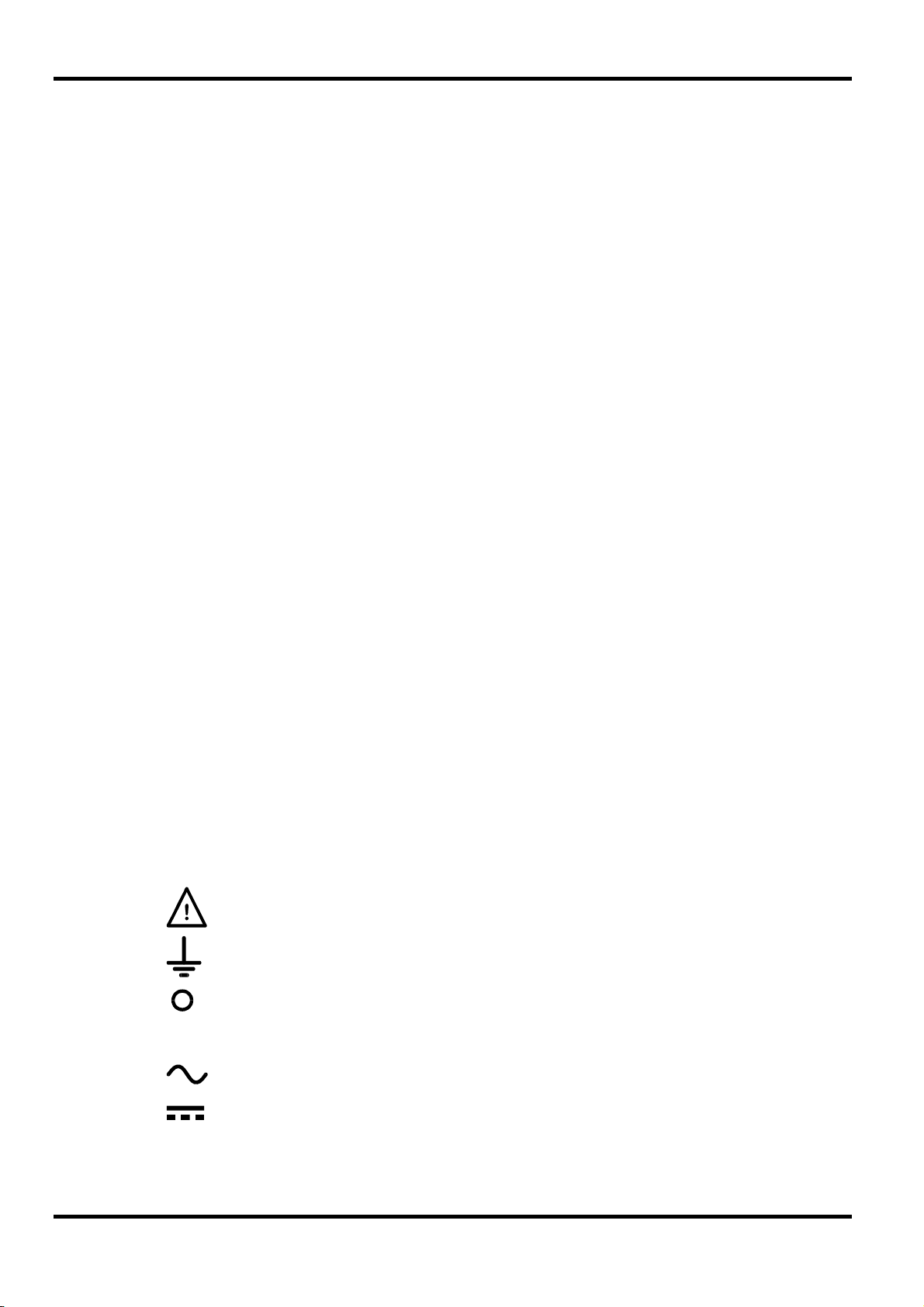
The following symbols are used on the instrument and in this manual:-
8
l
Caution - refer to the accompanying documentation, incorrect operation
may damage the instrument.
Earth (ground) terminal.
mains supply OFF.
mains supply ON.
alternating current (ac)
direct current (dc)
Page 13
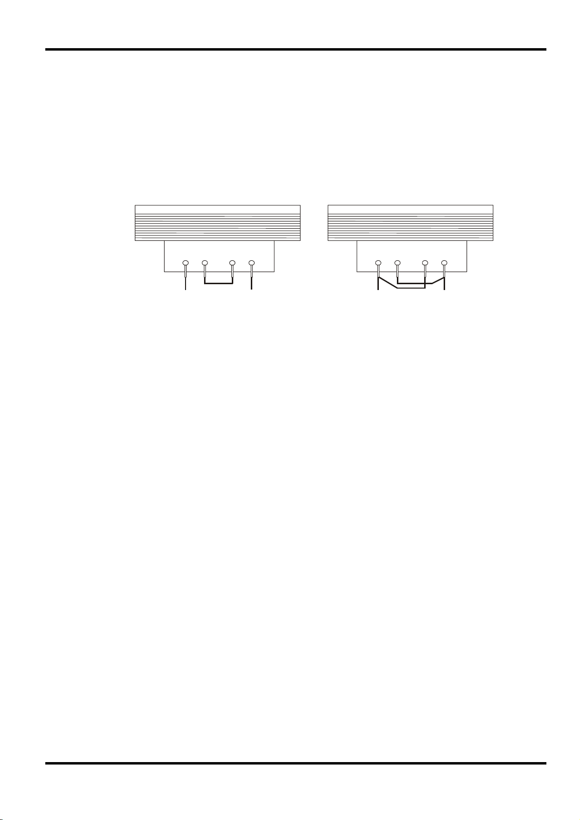
Mains Operating Voltage
Check that the instrument operating voltage marked on the rear panel is suitable for the local supply.
Should it be necessary to change the operating voltage, proceed as follows:
1. Ensure that the instrument is disconnected from the AC supply.
2. Remove the plastic push-rivets at each side edge of the top cover. Use the blade of a small
screwdriver to first ease out the rivet head and then fully remove the rivet body. Remove the two
rear panel screws securing the top cover; slide the cover back and lift off.
3. Change the transformer connections (two transformers on the dual) following the diagrams:
4. Re-assemble in the reverse order. To comply with safety standard requirements the operating
voltage marked on the rear panel must be changed to clearly show the new voltage setting.
Installation
230V Operation 115V Operation
BLUE BROWN BLUE BROWN
Fuse
The AC fuse is located in the fuse drawer in the lower part of the IEC inlet connector (single units) or
in separate fuseholders for each channel (dual units).
The correct fuse type in all cases is 20 x 5mm 250V HBC time-lag with the following rating:
Make sure that only fuses with the required current rating and of the specified type are used for
replacement. The use of makeshift fuses and the short-circuiting of fuseholders are prohibited.
Mains Lead
Connect the instrument to the AC supply using the mains lead provided. Should a mains plug be
required for a different mains outlet socket, a suitably rated and approved mains lead set should be
used which is fitted with the required wall plug and an IEC60320 C13 connector for the instrument
end. To determine the minimum current rating of the lead-set for the intended AC supply, refer to the
power rating information on the equipment or in the Specification.
Any interruption of the mains earth conductor inside or outside the instrument will make the instrument
dangerous. Intentional interruption is prohibited.
Mounting
This instrument is suitable both for bench use and rack mounting. A rack kit for mounting in a 19” rack
is available from the Manufacturers or their overseas agents.
230V operation : 1.6A (T)
115V operation : 3.15A (T)
WARNING! THIS INSTRUMENT MUST BE EARTHED.
Ventilation
The power supply is cooled by an intelligent multi-speed fan which aids vertical convection. Take care
not to restrict the air inlets underneath or the vents on the top. When rack-mounted allow adequate
space above and below the instrument and/or use a fan tray for forced cooling.
9
Page 14
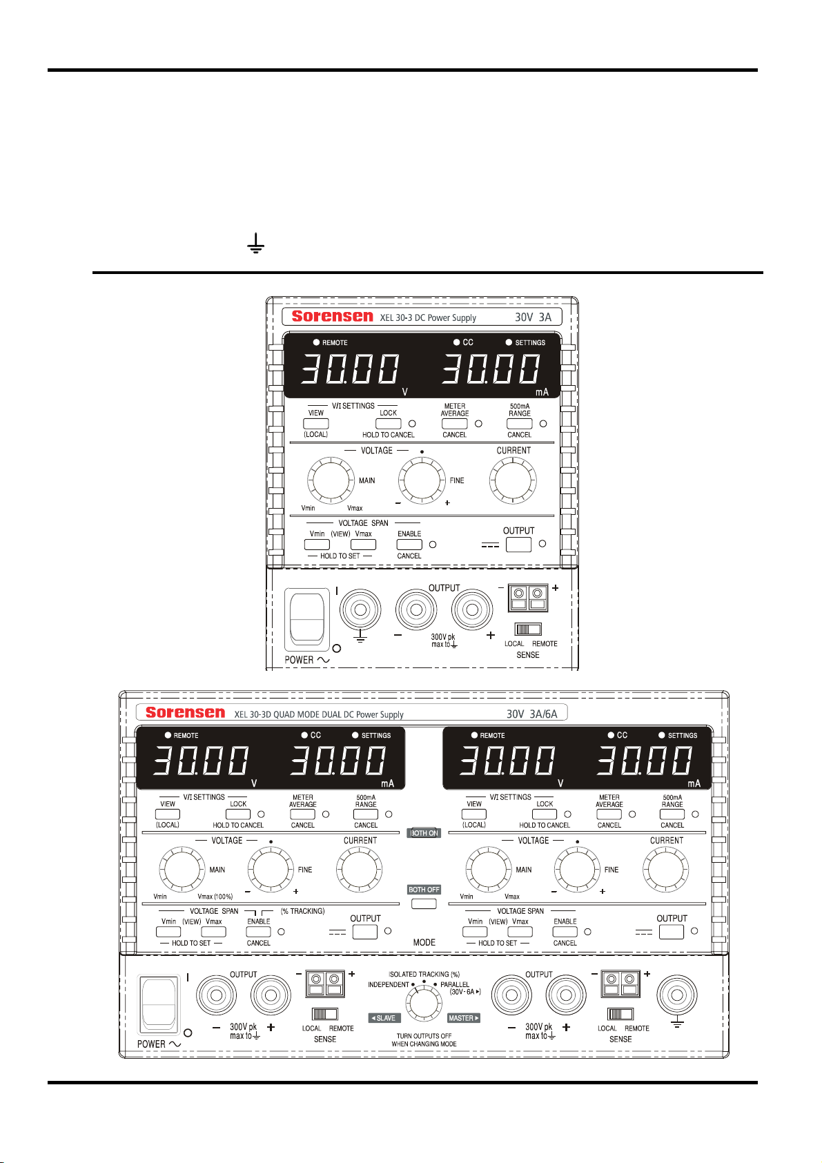
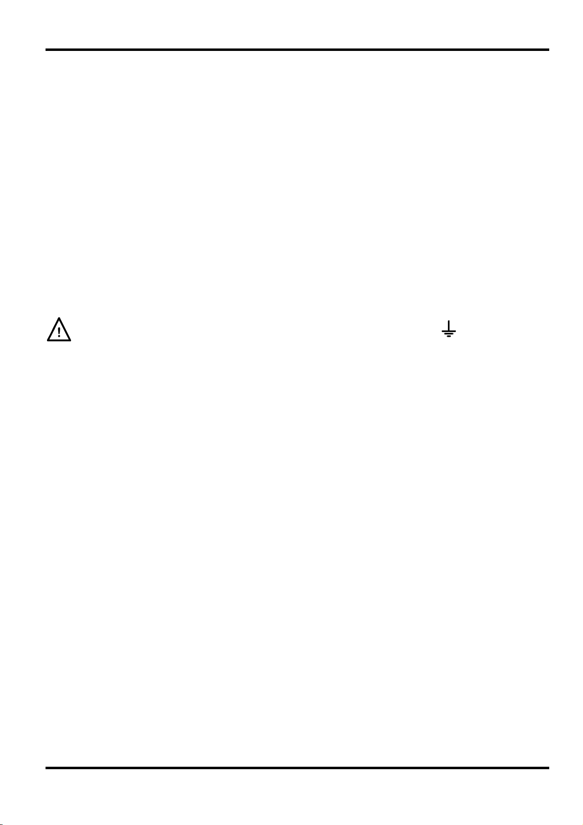
Front Panel Connections
The load should be connected to the positive (red) and negative (black) terminals marked
OUTPUT. Both are fully floating and either can be connected to ground.
Remote sense connections to the load, if required, are made from the positive (+) and
negative (−) SENSE terminals. Switch the LOCAL/REMOTE switch to REMOTE when remote
sensing is required. Switch back to LOCAL when remote sensing is not in use.
The terminal marked
FRONT PANEL VIEW
is connected to the chassis and safety earth ground.
Connections
10
Page 15
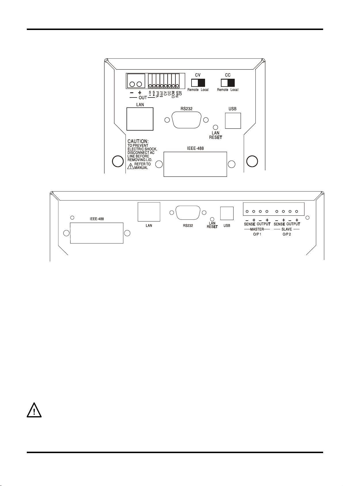
Rear Panel Connections
Non-programmable models have no rear panel connections. The rear panel connections of the
programmable units are shown below:
Main Output and Sense Terminals (all Programmable models)
The Output and Sense terminals are duplicated on the rear panel terminal block marked Output+,
Output −, Sense + and Sense − ; space restrictions on the single units limit the markings to +, −,
S+ and S− in the group marked OUT. These connections are paralleled with their front panel
equivalents.
Switch the LOCAL/REMOTE switch to REMOTE when remote sensing is required. When the
rear panel Output terminals are used, the use of remote sense is always recommended to ensure
that output regulation is maintained within specification; connections can be made to either the
front or the rear remote sense terminals but never to both pairs of terminals at the same time.
Switch back to LOCAL when remote sensing is not in use.
Analog Remote Control (Single Programmable models only)
Connections CV and CC provide analog control of the Output Voltage and Current Limit
respectively when slide switches CV and CC are set to Remote. The input scaling can be set
independently, by internal links, as 0 to 5 Volts (the factory default) or 0 to 10 Volts for 0 to 100%
of maximum output. The COMmon return signal is referenced to the positive output of the power
supply. CV and CC can be used independently or together.
Return slide switches CV and CC to Local when analog remote control is not in use.
Do not apply external voltages between the terminals exceeding the maximum for the selected
range (5V or 10V).
11
Page 16

Analog Out (Single Programmable models only)
Connections V
OUT
and I
provide analog outputs scaled to the set output voltage and set current
OUT
limit respectively. The scaling is fixed at 0 to 5 Volts for 0 to 100% of maximum output. V
I
are always present on the terminals, whether the instrument is under local or remote control.
OUT
The COMMON return signal is referenced to the positive output of the power supply.
Do not apply external voltages to these terminals.
Remote On/Off (Single Programmable models only)
A switch closure or logic low between connections Rem Off and COM will turn off the output. The
COM return signal is referenced to the positive output of the power supply.
Do not apply external voltages to these terminals.
RS232 (XEL-P models only)
9−pin female D−connector with pin connections as shown below. Can be connected to a
standard PC port using a fully wired 1:1 male-female cable without any cross-over connections.
Pin Name Description
1 RI
Passively asserted (+V through 10kΩ)
2 TXD Transmitted data from instrument
3 RXD Received data to instrument
4 CTS
5 GND Signal ground
6 RTS
Passively asserted (+V through 10kΩ)
7 DSR No internal connection
8 DTR
9 CD No internal connection
Signal ground is connected to instrument ground.
OUT
and
USB (XEL-P models only)
The USB port is connected to instrument ground. It conforms with USB 2.0 (Full Speed) and
accepts a standard USB cable. The Windows plug-and-play functions should automatically
recognize that the instrument has been connected. If the correct driver is not found, follow the
Windows on-screen prompts and install the required files from the CD supplied.
LAN (XEL-P models only)
The LAN interface is designed to meet LXI ( Lan eXtensions for Instrumentation) version 1.2; the
instrument is Class C compliant. Remote control using the LAN interface is possible using a
TCP/IP Socket protocol. The instrument also contains a basic Web server which provides
information on the unit and allows it to be configured. Since it is possible to misconfigure the LAN
interface, making it impossible to communicate with the instrument over LAN, a LAN
Configuration Initialize (LCI) mechanism is provided via a recessed switch on the rear panel
(marked LAN RESET) to reset the unit to the factory default.
Further details are given in the Remote Operation chapter. For more information on LXI
standards refer to www.lxistandard.org/home
GPIB (factory option on XEL-P models only)
The GPIB signal grounds are connected to the instrument ground. The implemented subsets are:
SH1 AH1 T6 TE0 L4 LE0 SR1 RL2 PP1 DC1 DT0 C0 E2
The GPIB address is set from the front panel.
12
Page 17
In this operating manual, front panel keys, controls and sockets are shown in capitals, e.g.
CURRENT, OUTPUT, LOCK. Messages displayed on the 7-segment LEDs are shown in a
different type-font, e.g. turn oFF, OtP trip. The additional features of the Quad-mode Dual
instrument are described together at the end of this chapter.
Switching On and Power-On Conditions
The POWER switch is located at the bottom left of the front panel. When the POWER switch is
turned on (
shows Volts and Amps.
For programmable XEL-P models the default display sequence at power on is different: the right
hand meter briefly indicates the instrument firmware revision followed by the interface firmware
revision (
few seconds, no physical LAN connection is found, the instrument's display will flash alternately
between the normal voltage and current values and the message
seconds. Indication of no LAN connection at power on is an essential LXI compliance
requirement but can be disabled by the 'NOLANOK 1' command over any interface, see the LAN
Error paragraph in the Remote Interface Operation section for further details. This change of
power on setting is retained until reversed by a 'NOLANOK 0' command or by the use of the rear
panel LAN RESET switch to restore the factory default LAN setting, see the LAN paragraph in the
Remote Interface Operation section.
Note that the display messages do not affect the operation of the power supply itself.
At power on, the factory default setting is for the output to be off. The preset output volts and
current will be determined by the present control settings and shown in the display. All other
settings will be the same as they were at last power off.
l ) the right hand meter briefly indicates the firmware revision before the display
IF shows in the left hand meter) before the display shows Volts and Amps. If, after a
Manual Operation
LAn Err, for the next 10
Repeating the procedure will change the setting back to the previous state. Note that the poweron status of the two outputs of the dual supply need to be set individually.
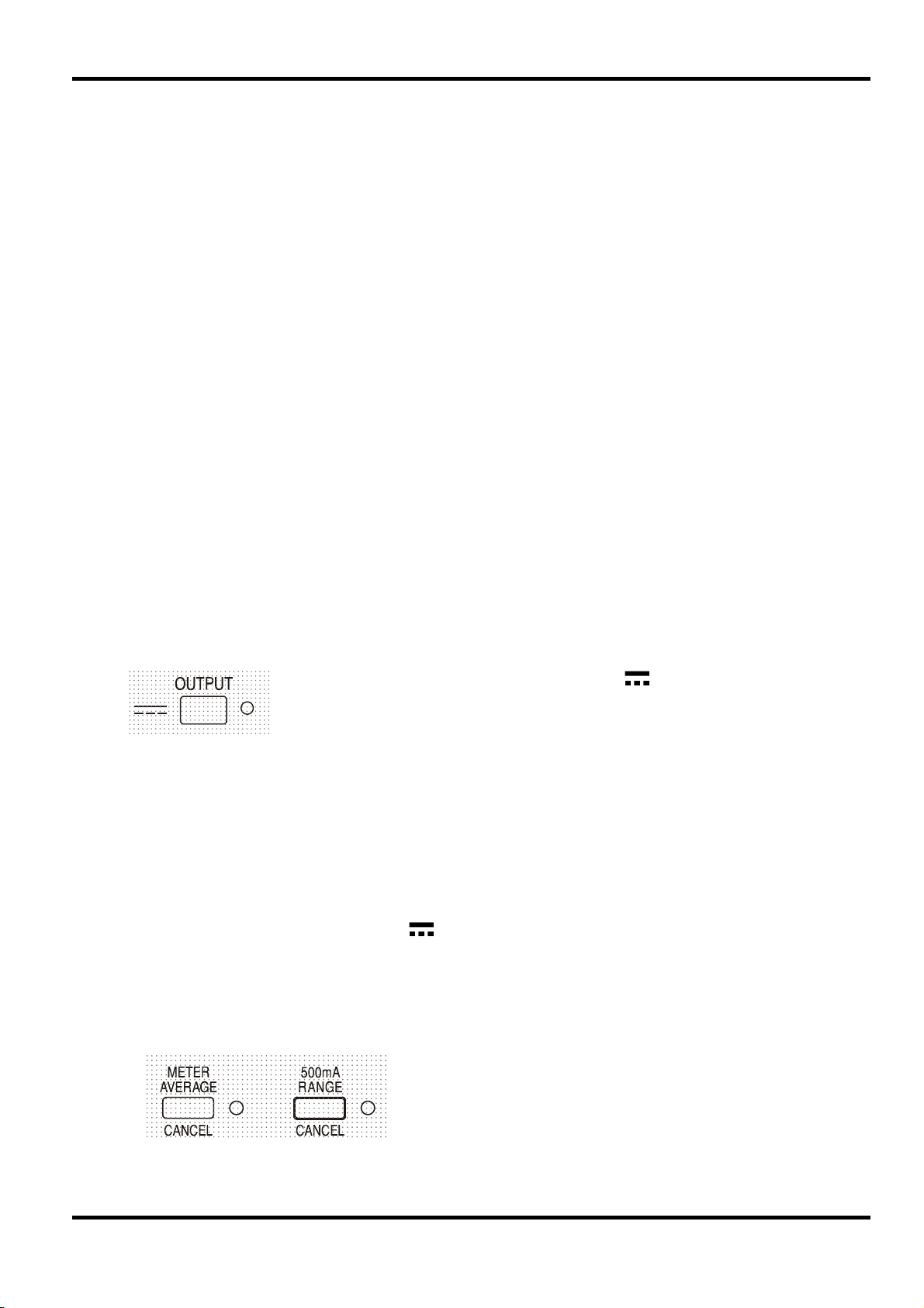
Output Control
Setting Up the Output
With the POWER switch on and the
accurately preset using the VOLTAGE and CURRENT controls; the left-hand meter shows the set
voltage, the right-hand meter shows the set maximum current and the SETTINGS indicator is lit.
When the output switch is switched on, the OUTPUT indicator lights; the left-hand meter now
shows the actual voltage and the right-hand meter the actual load current.
The dc output state at power-on can be set to be ‘always off’ or ‘same as
at last power-off’. The setting can be changed as follows. With the VIEW
key held down, press and hold down the
will first show the present setting for 1 second (
default is still selected) before flashing the new setting for 2 seconds (
LASt Set in this instance). After 2 seconds the new setting is shown
continuously in the display and the change is implemented; release the
OUTPUT and VIEW keys.
OUTPUT off the output voltage and current limit can be
The upper limit of the CURRENT control can be switched
between the maximum for this model and 500mA with
alternate presses of the 500mA RANGE key to give finer
current limit setting and measurement resolution (0.1mA up to
500mA); the indicator beside the key is lit when the 500mA
range is selected.
OUTPUT key; the display
OP OFF if the factory
13
Page 18
To change the current limit range the output must be switched off; if the output is on the warning
message
range remains unchanged.
Constant Voltage
The output voltage is adjusted using the main and fine VOLTAGE controls; the CURRENT control
sets the maximum current that can be supplied.
Constant Current
If the load resistance is low enough such that, at the output voltage set, a current greater than the
current limit setting would flow, the power supply will automatically move into constant current
operation. The current output is adjusted by the CURRENT control and the VOLTAGE controls
set the maximum voltage that can be generated.
The CC indicator lights to show constant current mode.
Instantaneous Current Output
The current limit control can be set to limit the continuous output current to levels down to 1mA
(0.1mA on 500mA range). However, in common with all precision bench power supplies, a
capacitor is connected across the output to maintain stability and good transient response. This
capacitor charges to the output voltage and loading of the output will produce a current pulse as
the capacitor discharges which is independent of the current limit setting.
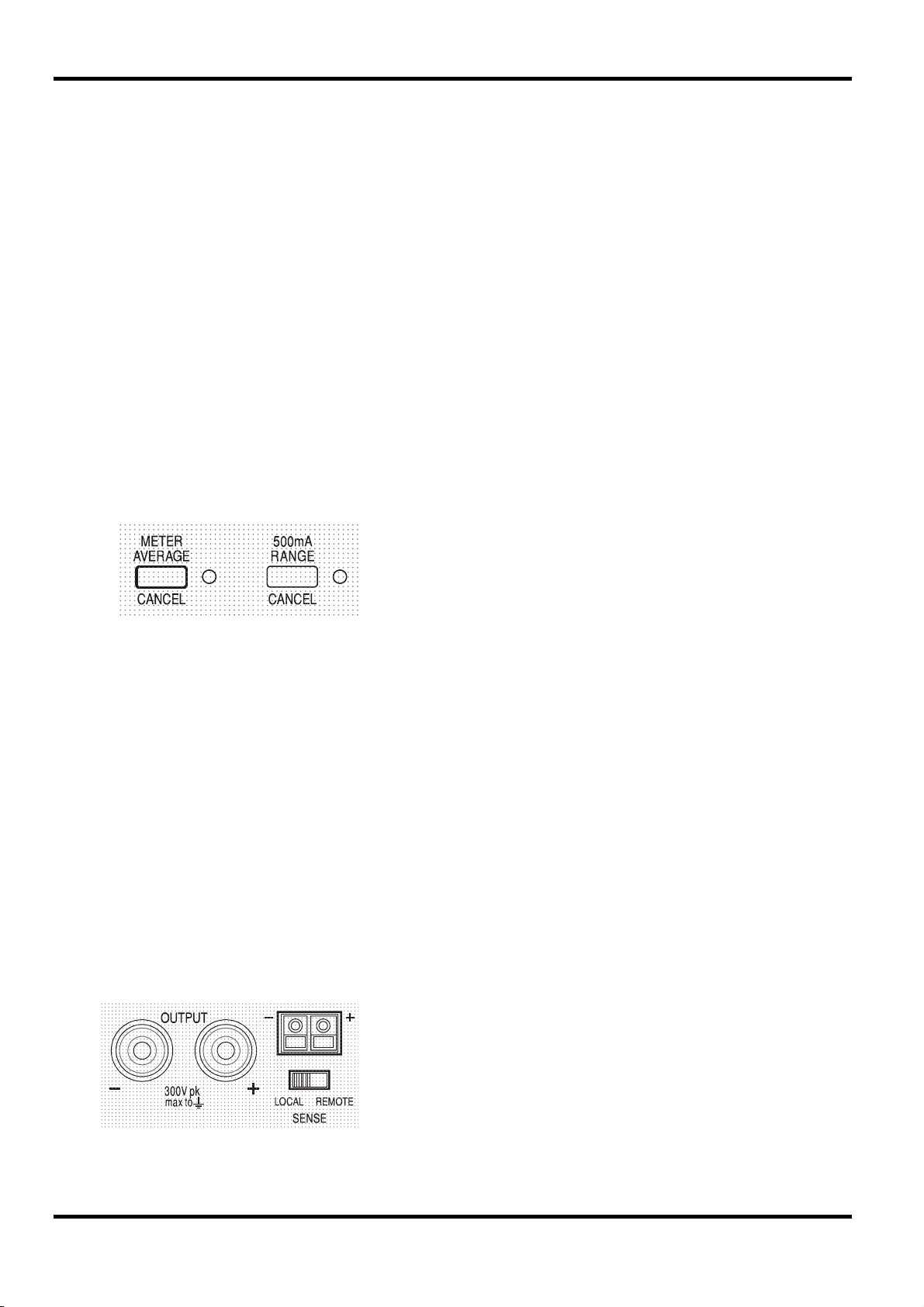
Current Meter Averaging
turn oFF is shown briefly in the display, the OUTPUT indicator flashes and the
To reduce the measurement jitter with rapidly varying load
currents a 2-second time constant can be selected by pressing the
METER AVERAGE key; the indicator beside the key lights when
meter averaging is selected. Press the key again to CANCEL
meter averaging and return to the standard 20ms time constant.
Efficiency
The power supply minimizes dissipation by using electronic line frequency pre-regulation to
maintain a low overhead voltage to the output regulators. In addition, to optimize operation at
extremes of line input voltage and DC output power, the transformer secondary is intelligently tapchanged by a relay. Hysteresis is used at the threshold point to prevent unnecessary switching
when the output is set at about that level. Apart from an audible ‘click’ the user will be unaware
that the relay has switched; there will be no disturbance on the output.
Programmable models use special transformers which do not require relay tap-changing.
Connection to the Load
The load should be connected to the positive (red) and negative (black) OUTPUT terminals. Both
are fully floating and either can be connected to ground.
Remote Sensing
The unit has a very low output impedance, but this is inevitably increased by the resistance of the
connecting leads. At higher currents this can result in significant differences between the
indicated source voltage and the actual load voltage (two 20mΩ connecting leads will drop 0.2V
at 5 Amps, for instance)
.
This problem can be minimised by using short, thick, connecting
leads, but where necessary it can be completely overcome by
using the remote sense facility.
This requires the sense terminals to be connected to the output
at the load instead of at the source; insert wires into the springloaded SENSE terminals and connect directly to the load. Switch
the LOCAL/REMOTE switch to REMOTE.
14
Page 19
To avoid instability and transient response problems, care must be taken to ensure good coupling
between each output and sense lead. This can be done either by twisting the leads together or by
using coaxially screened cables (sense through the inner). An electrolytic capacitor directly
across the load connection point may also be beneficial. The voltage drop in each output lead
must not exceed 0.5 Volts.
Switch the LOCAL/REMOTE switch back to LOCAL when remote sensing is not in use.
Output Connection and Remote Sensing on Programmable Models
All programmable models have duplicate rear panel Output and Sense terminals, appropriate for
when the instruments are used in a rack. When the rear panel Output terminals are used, the
use of remote sense is always recommended to ensure that output regulation is maintained within
specification; connections can be made to either the front or the rear remote sense terminals but
never to both pairs of terminals at the same time. Connect the Sense terminals to the load,
following the guidelines above, and set the LOCAL/REMOTE switch to REMOTE.
If the rear panel Output terminals are used without remote sense make sure that the front panel
switch is set to LOCAL. Regulation will be degraded a little when local sense is used because of
the additional small voltage drop in the wiring to the rear terminals.
Series or Parallel Connection with Other Outputs
The outputs of the power supply are fully floating and may be used in series with other power
supply units to generate high DC voltages up to 300V DC.
The maximum permissible voltage between any terminal and earth ground (
WARNING! Such voltages are exceedingly hazardous and great care should be taken to shield
the output terminals for such use. On no account should the output terminals be touched when
the unit is switched on under such use. All connections to the terminals must be made with the
power switched off on all units.
It should be noted that the unit can only source current and cannot sink it, thus units cannot be
series connected in anti-phase.
The unit can be connected in parallel with others to produce higher currents. Where several units
are connected in parallel, the output voltage will be equal to that of the unit with the highest output
voltage setting until the current drawn exceeds its current limit setting, upon which the output will
fall to that of the next highest setting, and so on. In constant current mode, units can be
connected in parallel to provide a current equal to the sum of the current limit settings.
Protection
The output has intrinsic short-circuit protection and is protected from reverse voltages by a diode;
the continuous reverse current must not exceed 3 Amps, although transients can be much higher.
If the applied reverse voltage can source more current than the set current limit, and the output is
on, then the output will go into current limit (the CC indicator will flash) and its display will show
the reverse voltage across the protection diode; if the output is off, just the CC indicator will flash.
In common with all series regulated single-ended power supplies, the unit is not capable of
sinking current provided from an external source. If a voltage greater than the set output voltage
of the unit is applied from an external source, the internal regulator will turn off and no current will
flow; if the output is turned on the voltage meter will read the applied voltage. No damage will
result providing the applied voltage does not exceed the maximum output voltage of the power
supply by more than 20 Volts.
) is 300VDC
With the OUTPUT off the load is still connected to the power supply output stage; the output
voltage is simply set to zero. Do not apply external voltages to the power supply terminals in
excess of 20V above the rated output voltage, even with the output off, or damage may result.
15
Page 20
y
Over-temperature Protection
An internal sensor will detect over-temperature due to blocked airflow, fan failure or other circuit
fault. Over-temperature will turn the output off, the OUTPUT indicator will flash, and the display
will show the message
removed, and the instrument has cooled down, the output indicator will go off but the message
OtP triP continues to show. Pressing the OUTPUT key once will change the display to show
the preset voltage and current (the SETTINGS indicator will be lit) but the output will remain off;
pressing it a second time will turn the output on normally.
If the OUTPUT key is pressed while the instrument is still over-temperature (OUTPUT indicator is
flashing), the message
SETTINGS indicator will be lit) but the output will remain off; each subsequent press of the
OUTPUT key causes the
off until the over-temperature condition ends.
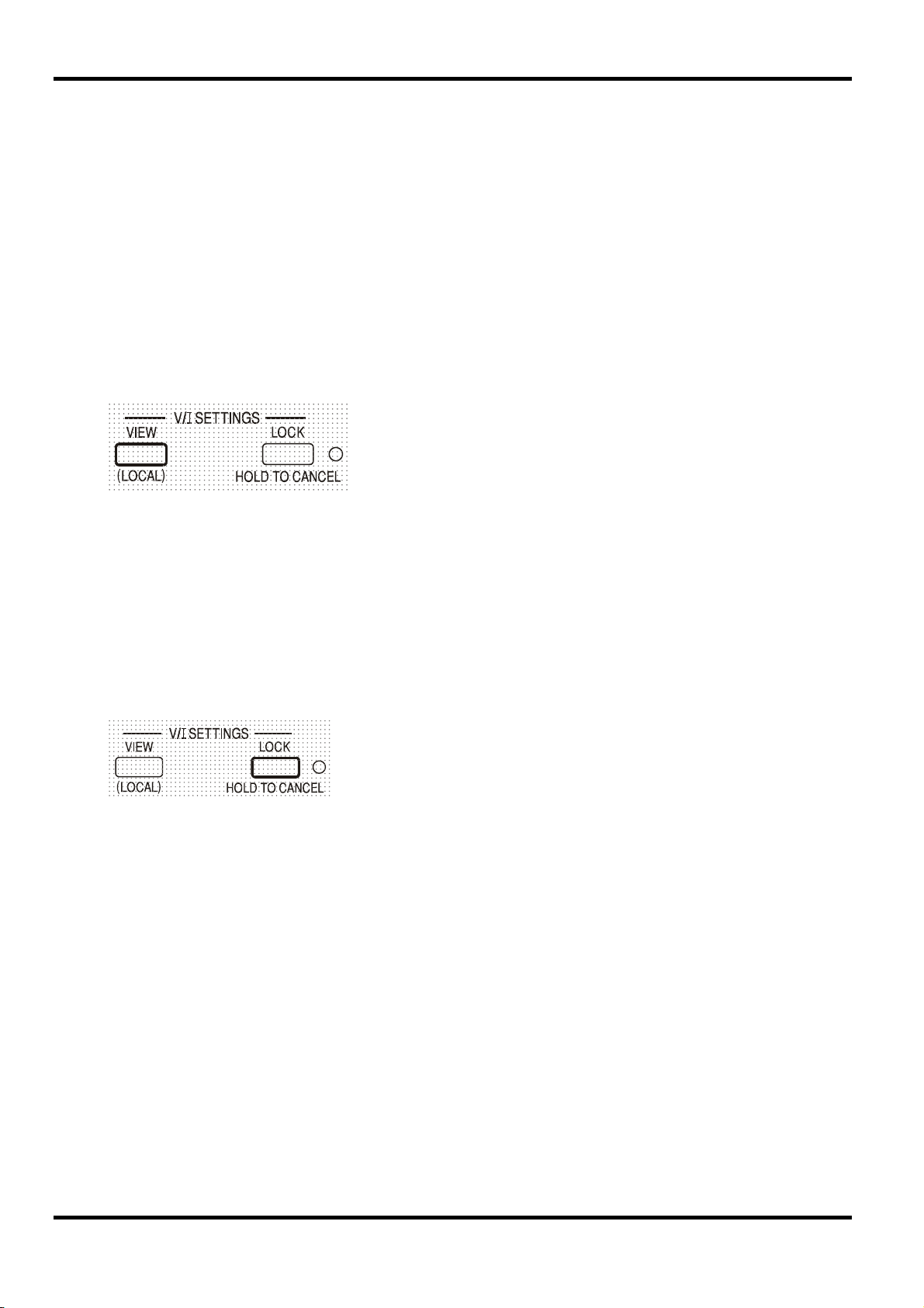
View Settings
Lock Settings
OtP triP . When the cause of the over-temperature has been
OtP triP is replaced by the preset voltage and current (the
OtP triP message to be displayed briefly but the output will remain
The set voltage and current limit are always shown when
the output is off but can also be viewed when the output is
on by pressing the VIEW key; the SETTINGS indicator is lit
whilst the VIEW ke
is pressed.
Pressing the LOCK key digitally locks the set voltage and current limit. The settings are stored
with a precision of better than 1 digit. Subsequent adjustments of the VOLTAGE and CURRENT
controls will have no effect.
Because canceling LOCK will cause the output settings to change if the VOLTAGE and
CURRENT control positions have been moved, warning reminders are given before LOCK is
cancelled. Press and hold the key to cancel LOCK.
If the OUTPUT is off (the safe condition) the display will flash the ‘unlocked’ settings twice before
the change is implemented; the LOCK lamp goes off.
Releasing the LOCK key at any time while the display is flashing will abort the LOCK cancellation.
Attempting to change the current limit range (see Setting up the Output section) or the voltage
span limits (see Voltage Span section) with LOCK enabled is not allowed; if attempted, the
message
output is also on when these actions are attempted the message
the display (accompanied by the output indicator flashing) followed by the message
(with the LOCK indicator flashing).
The LOCK status at power on is the same as at last power off.
Unloc is shown briefly in the display and the LOCK indicator is also flashed. If the
If the output is still on, OP on (output on) will flash twice in the
display, followed by flashing of the new ‘unlocked’ settings for 2-3
seconds (slowly at first, then faster) before the change is finally
implemented; the LOCK lamp goes off when the change is made.
turn oFF is first shown in
Unloc
Using Voltage Span
The VOLTAGE SPAN (V-Span) capability allows the end-stop values of the VOLTAGE controls to
be redefined by the user such that the controls operate within a specific, narrower, voltage range.
This not only has the advantage of protecting against the accidental application to the load of
voltages outside of the range, but also provides high-resolution analog control over the specified
voltage range using the full 300º rotation of the voltage controls.
16
Page 21
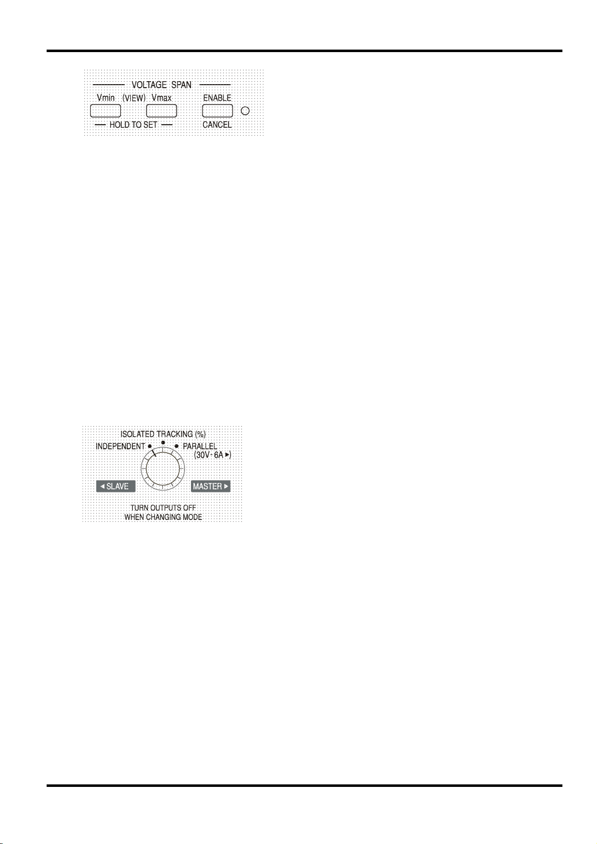
V-Span is turned on or off with the ENABLE key. The
ENABLE lamp is lit when V-Span is selected. The
factory default is V
= 3V, V
min
max
= 5V
Because turning V-Span on will always change the output voltage, it can only be enabled or
cancelled with the output off. If attempts are made to enable or cancel V-Span with the output on,
the display will briefly show the message
turn oFF to prompt the user to turn the output off.
To set new values for V
min
or V
the V-Span function must be off (cancelled).
max
The lower voltage limit is defined by using the MAIN and FINE VOLTAGE controls to set exactly
the required value; the V
key is then held pressed until the left-hand side (V) display stops
min
flashing and the right-hand side (mA) display shows
time by a short press (<1 second) of the V
key. The upper voltage limit is set and VIEWed in
min
exactly the same way using the VOLTAGE controls and the V
The limits can be set in any order and to any value within the output range of the instrument but
V-Span can only be turned on with the ENABLE key if V
met, the message Set Err is briefly displayed and the V-Span function is not implemented.
When V-Span is enabled, the range of the MAIN VOLTAGE control is exactly V
the FINE control is set at its mid-point, marked on the panel with a • . The FINE control itself
can be usefully used to give an additional fine adjustment of ±1% (of the voltage span).
The V-Span status at power on is the same as at last power off.
Mode Control of the Quad-Mode Dual
However, it is not possible to guarantee that there will never be any unwanted transients as the
mode is switched and the recommendation is therefore that both outputs should always be
switched off before any mode change.
The four operating modes of the Quad-Mode Dual are
described below; the mode is changed using the MODE
rotary switch. To prevent unintended voltages being
accidentally applied to the circuits connected to the outputs,
changing modes will always cause both outputs to be
switched off.
Set. The setting can be VIEWed at any
key.
max
max
≥ (V
+ 0.1V); if this condition is not
min
to V
min
max
when
Independent
Set the MODE switch to INDEPENDENT. The two outputs are completely independent and
electrically isolated; each can be set as described in the preceding Output Control section.
It is not possible to switch from Independent mode to Tracking with LOCK set on the Slave
output. The message
Un loc is shown in the Slave display and LOCK must first be switched
off (in Independent mode) before the Tracking modes can be used.
See also the Retained Slave Settings paragraph.
Isolated Tracking
Set the MODE switch to ISOLATED TRACKING. The two outputs remain electrically isolated but
the Voltage controls of the Master output set an identical voltage on the Slave output. The
Current controls of the Slave remain independent, including the 500mA Range and Meter
Average functions.
17
Page 22
The electrical isolation permits the two outputs to be connected to provide, for example, tracking
voltages of opposite polarity or identical voltages connected to different system references (e.g.
digital ground and analog ground).
The LOCK and VOLTAGE SPAN functions of the Master operate exactly as described previously
and, because the output voltage of the Slave tracks the Master, they control the Slave output
voltage as well. Note that only the output voltage of the Slave is ‘locked’ when the Master LOCK
is used; the current controls of the Slave, including the 500mA Range and Meter Average
functions, remain independent.
The LOCK key on the Slave output is ignored and pressing it causes the message
be shown momentarily in the Slave display as a reminder.
It is possible to switch from Tracking mode back to Independent mode with LOCK still set on the
Master. The ‘Master’ (right-hand output) settings stay ’locked’ but the settings of the left-hand
output, are not locked.
The Voltage Span keys of the Slave have a different function in Tracking mode, see next section.
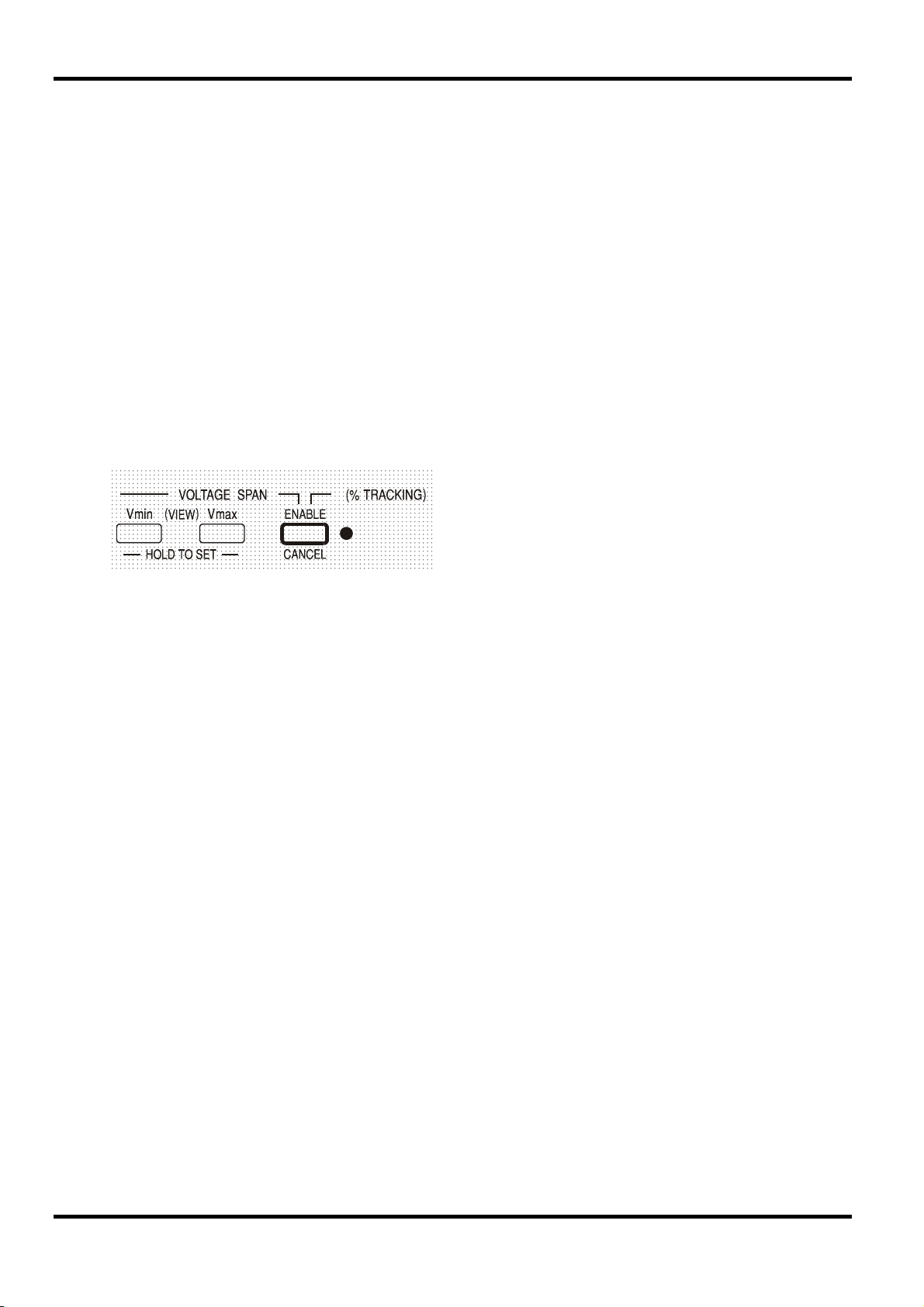
Isolated Ratio (%) Tracking
Set the MODE switch to ISOLATED TRACKING.
The instrument operates as described above for Tracking mode but the Slave voltage can be set
to a percentage (0% to 101%) of the Master voltage using the Slave Voltage controls. The ratio is
then maintained as the Master voltage is varied.
Pressing ENABLE again returns the Slave to standard Tracking mode (ENABLE lamp off).
Ratio Tracking can only be enabled or disabled with the Slave output off. If the output is on the
display will briefly show the message
not be implemented.
Whenever Ratio Tracking mode is enabled the Slave display momentarily shows
before reverting to show the actual output voltage now set.
In trac to
Ratio Tracking is enabled by pressing the
ENABLE key in the Slave VOLTAGE SPAN
section (ENABLE lamp on)
turn oFF when ENABLE is pressed and the change will
Pcnt on
Parallel
18
The percentage value can be shown at any time by pressing either the V
Slave output. With either key held down the Slave display shows the percentage setting in the
form
90.0 Pcnt and the Slave Voltage controls can be used to set the ratio percentage
required. The ratio percentage can be set prior to Ratio Tracking being enabled (ENABLE lamp
off).
The LOCK and VOLTAGE SPAN functions of the Master operate exactly as described previously.
However, with Ratio Tracking enabled, the Slave Voltage controls can still be used to adjust the
ratio percentage of the Slave voltage even though the Master voltage is locked. The Ratio
Tracking mode status at power on is the same as at last power off. See also the Retained Slave
Settings paragraph.
The MODE switch is set to PARALLEL. The instrument operates in true parallel mode with all of
the power available from the Master output which can then supply up to 6 amps. The Slave
output is disabled and its displays are turned off.
In Parallel mode the value of the current limit is doubled for the same setting of the Current limit
control, including the 500mA range which becomes 1000mA max; as a warning, when Parallel
mode is first selected, the current display flashes twice before steadily displaying the new limit.
Similarly, the current display is flashed twice when the mode is changed from Parallel to Tracking,
as a warning that the Master output current limit has now halved.
min
or V
key of the
max
Page 23
The LOCK and VOLTAGE SPAN functions of the Master operate exactly as described previously.
It is possible to switch from Parallel mode back to Tracking mode (and vice-versa) with LOCK still
set on the Master; both the Voltage and Current controls of the Master stay in LOCK, as
described previously. However, the actual set current limit of the Master will still double (switching
from Tracking to Parallel) or halve (switching from Parallel to Tracking), even though LOCK is set,
but the current display flashes as a warning that this has happened.
Retained Slave Settings
If V-Span is enabled on the Slave output in INDEPENDENT mode, it is disabled when TRACKING
mode is selected but re-enabled when INDEPENDENT mode is re-selected.
If Ratio (%) Tracking is enabled on the Slave output in TRACKING mode, it is disabled when
INDEPENDENT or PARALLEL are selected but re-enabled when TRACKING mode is reselected.
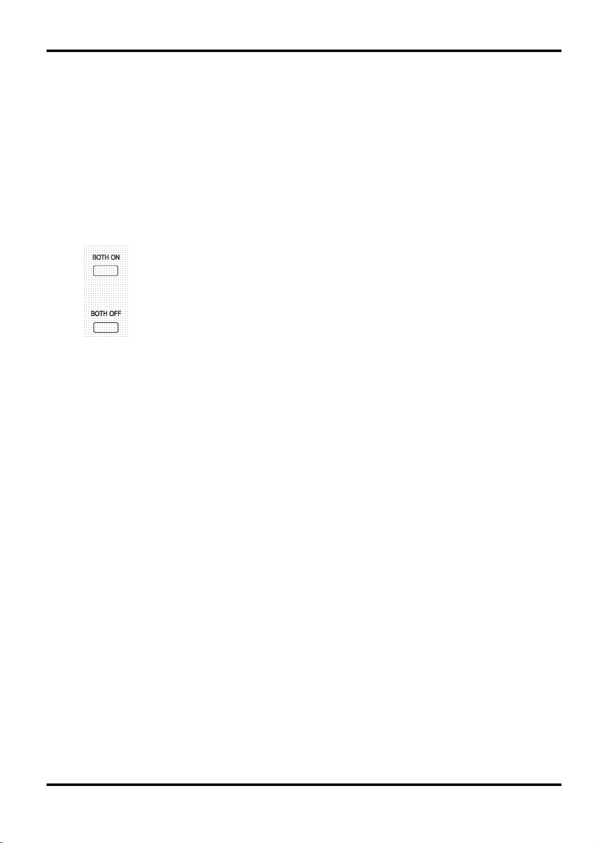
Simultaneous Output On/Off Control
The Both On / Both Off keys are in addition to the individual OUTPUT switches
and permit both outputs to be turned on or off synchronously with a single key
press. The Both On / Both Off keys operate in all four configuration modes.
19
Page 24
Remote analog control of output voltage and current is possible using variable external control
voltages applied between the rear panel CV and COM or CC and COM inputs respectively.
The Analog Out control voltages V
control a ‘slave’ unit via the slave’s CV and CC inputs respectively.
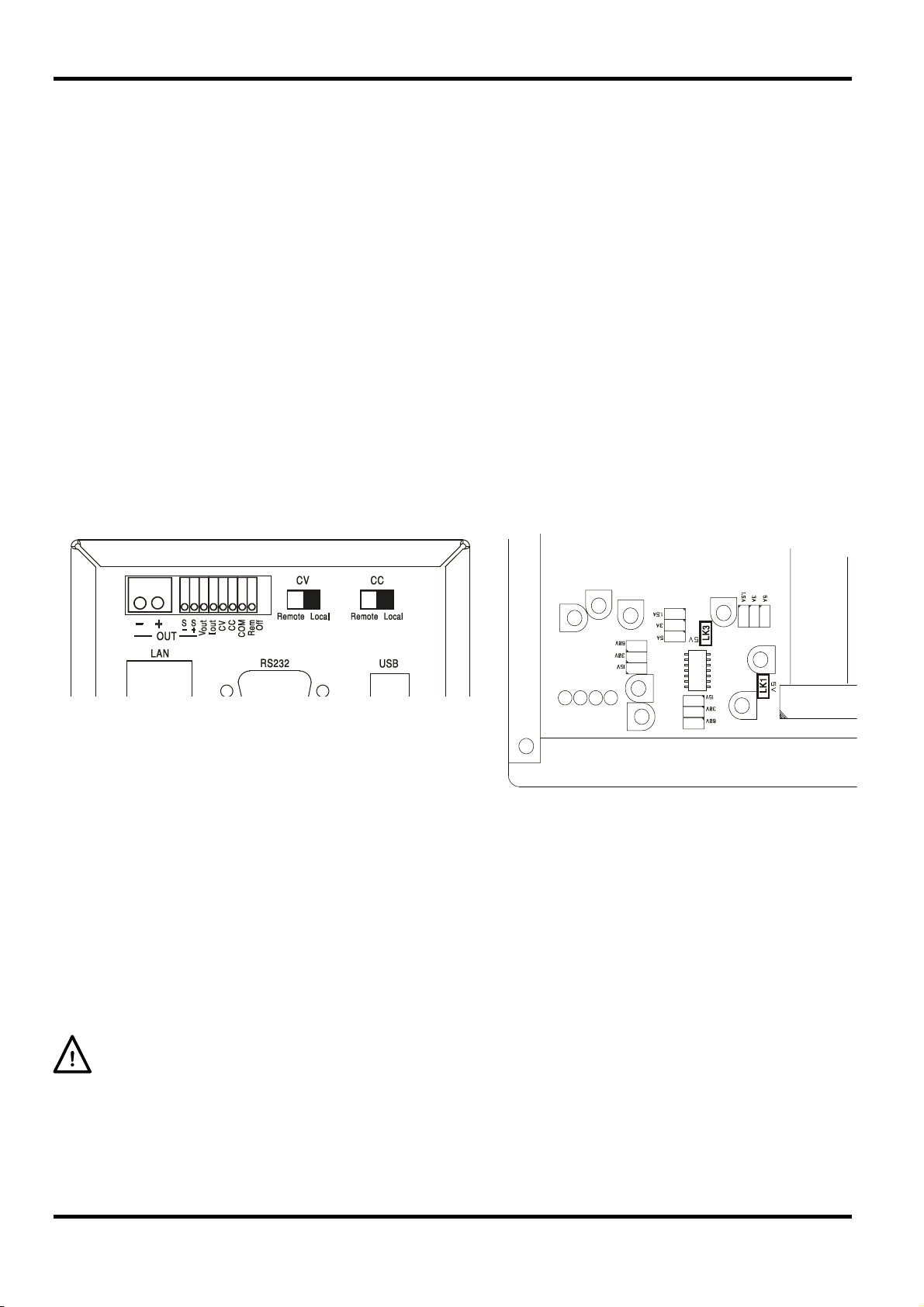
Analog Voltage Control
Remote analog voltage control is achieved by setting the rear panel CV switch to Remote and
applying a programming voltage between the inputs CV and COM.
The front panel VOLTAGE controls are disabled when Remote is set on the CV switch. Set the
switch to Local to return control to the front panel.
The default input voltage scaling is 0V to 5V for 0 to 100% of the rated output voltage. The input
voltage scaling can be changed to be 0V to 10V by removing an internal shorting link.
Disconnect the instrument from the AC source and remove the cover as described in the
Installation section. Referring to the top view of the instrument shown in the drawing, remove the
tall shorting link in position LK1.
Remote CV can be used with either Local or Remote CC.
Remote Analog Control
(Single programmable models only)
out
and I
of one unit acting as a ‘master’ can be used to
out
Analog Current Control
Remote analog constant current control is achieved by setting the rear panel CC switch to
Remote and applying a programming voltage between the inputs CC and COM. Remote analog
current control can only be used on the high current range, not the 500mA range.
The front panel CURRENT control is disabled when Remote is set on the CC switch. Set the
switch to Local to return control to the front panel.
The default input voltage scaling is 0V to 5V for 0 to 100% of the rated maximum current (high
range only). The input voltage scaling can be changed to be 0V to 10V by removing an internal
shorting link. Disconnect the instrument from the AC source and remove the cover as described
in the Installation section. Referring to the top view of the instrument shown in the drawing,
remove the tall shorting link in position LK3.
Remote CC can be used with either Local or Remote CV.
CAUTION. Do not apply external control voltages to either the CV or CC input that exceed the
maximum for the set input range (5V or 10V). The inputs are protected against excess voltages
but the instrument will attempt to supply an output voltage or current in excess of its maximum
rating if the control voltage exceeds its range limit, with possible consequential damage. If the
condition persists, OVP and/or OCP may trip the output off, see next section.
20
Page 25
OVP and OCP
OVP (over-voltage protection) and OCP (over-current protection) are implemented in firmware
and can only be set and used when under remote control via the RS232, USB, LAN (LXI) or GPIB
interfaces. Setting resolutions are 10mV and 1mA and typical response times are 500ms.
However, in local mode, OVP and OCP are still active but automatically default to 105% of the
instrument's range maximum. This usefully provides shut-down protection in the event of
prolonged application of a CV or CC control voltage which attempts to set the output beyond
105% of the range maximum.
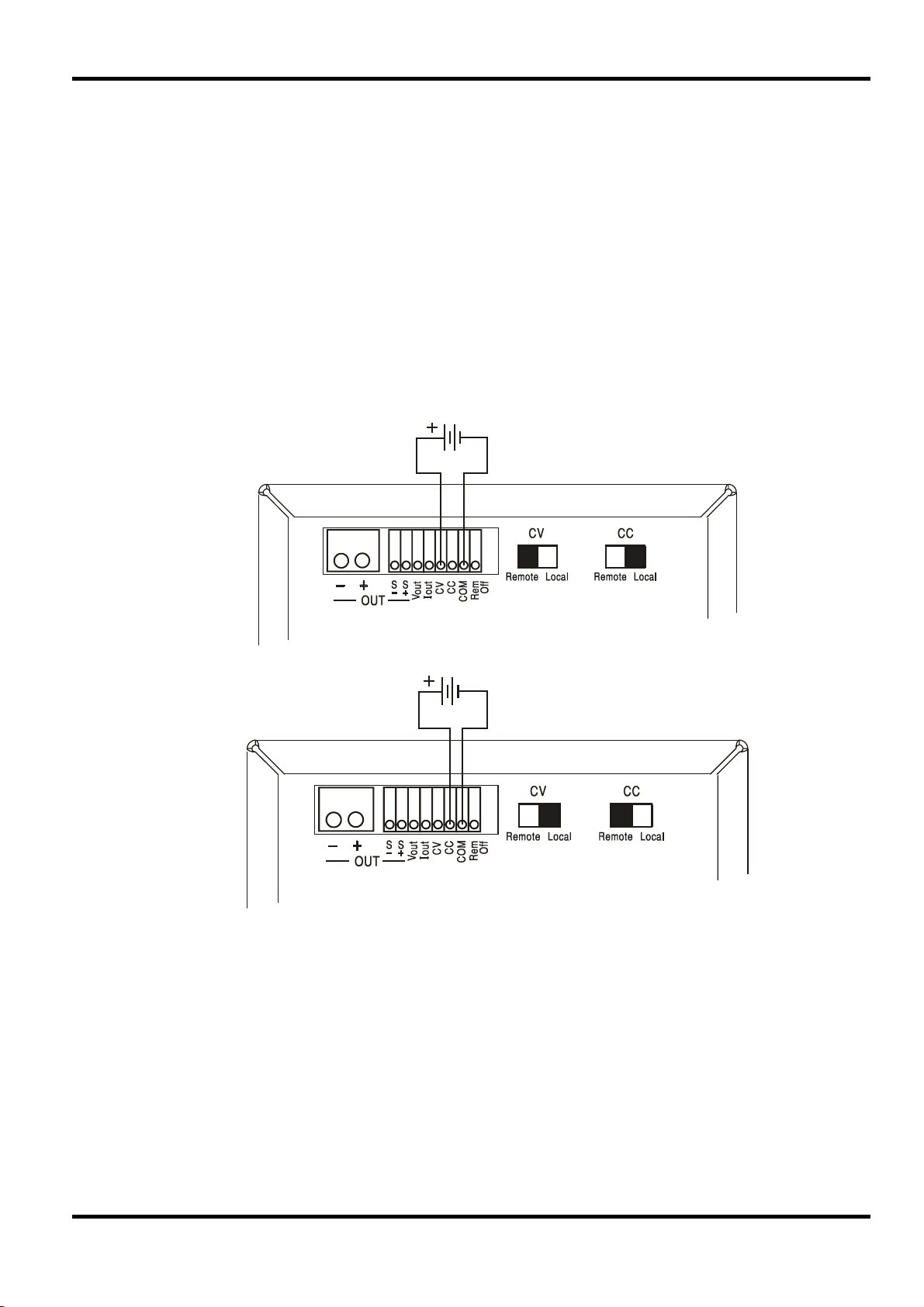
Practical Considerations when using CV and CC
The stability of the control voltages directly affects the stability of the output. Any noise on the
control signals will generate noise on the output. To minimize noise on the output connect the
control voltages to the CV, CC and COM inputs using twisted or screened pairs (screens
grounded at one end only) and keep the connections as short as possible. The diagrams below
show the connections for Constant Voltage (CV) and Constant Current (CC) control using an
external voltage.
Constant Voltage Control
Note that when the OUTPUT is on, the instrument’s display always shows the actual output
voltage and current, whichever control source is active. However, when the OUTPUT is off, the
display will show the preset voltage and current set by the front panel controls (or the digital
interface if active) and not the values determined by the CV and CC inputs even if they have been
made active (CV and CC set to Remote). To avoid confusion it is good practice to set the front
panel controls to minimum when remote CV and CC are used.
Analog Out Control Voltages
Analog Out control voltages V
for which the active source can be the front panel controls, the digital interface (RS232, USB,
LAN or GPIB) or the remote analog inputs CV and CC. V
100% of the rated output voltage and current (high range only) generate 0V to 5V at the rear
panel V
I
always corresponds to the set current, whether the output is on or off, but V
out
out
and I
terminals with respect to COM. COM is connected to the positive output.
out
the output is off.
Constant Current Control
and I
out
are generated from the actual internal control voltages,
out
out
and I
are scaled such that 0 to
out
goes to 0V when
out
21
Page 26
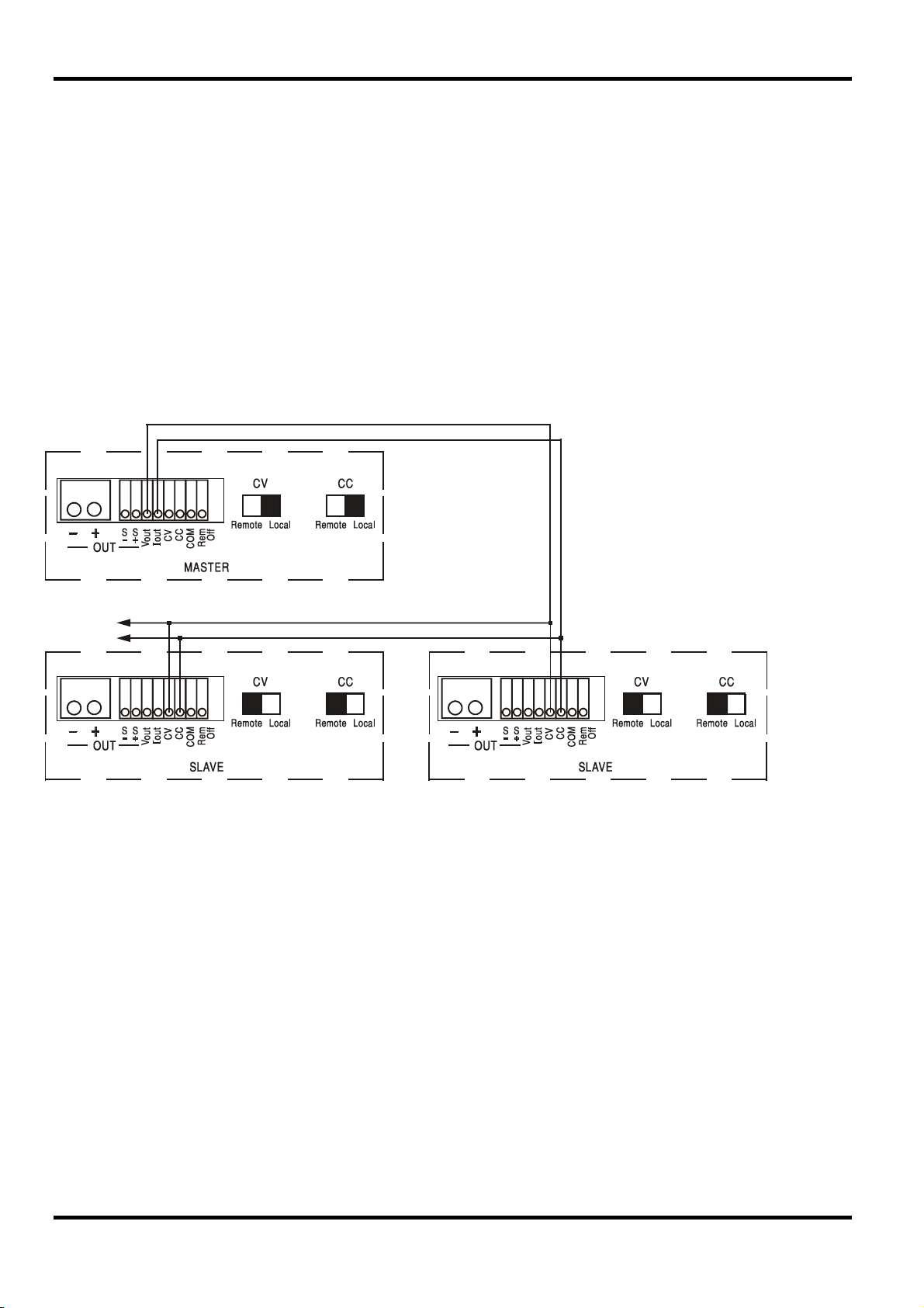
Parallel Operation in Master-Slave Configuration
Parallel operation in Master-Slave configuration permits higher output currents to be realized with
equal current sharing between units and control of both voltage and current from a single unit. All
units should be of the same type, i.e. same rated output voltage and current. The diagram shows
3 units connected in parallel. For equal current sharing each unit must be independently
connected to the load with pairs of wires of equal gauge and length to ensure equal voltage
drops. Connect the V
out
and I
of the master to the CV and CC inputs of the slaves (set CV and
out
CC switches to Remote) as shown.
Note: Do not make connections to the COM inputs of the slaves because these are already
linked to the master via the positive output connections.
The voltage and current of the master can be set by either the front panel controls via the digital
interface, or by an external voltage applied to its own CV and CC analog control inputs.
Parallel Operation in Master-Slave Configuration
Notes:
1. Units can be wired for CV (constant
voltage, CC (constant current) or both (both
shown). Set CV and/or CC switches of
slaves to Remote.
2. Connect outputs in parallel using equal
length wires to the load.
3. If remote sensing is required use only
remote sense from the master to the load.
4. For constant current operation set the
required voltage overhead on the master.
In constant voltage mode the voltage across the load is that set on the master unit by its front
panel controls, via the digital interface or by the analog CV remote control input. The current limit
for the system (i.e. the current in constant current mode) is the current limit set on the master x n,
where n is the total number of units connected in parallel.
Note: Because the analog remote control inputs are not isolated (COM is connected to the
positive output terminal) it is not possible to use analog remote control with instruments
connected in series.
Remote Off
A switch closure or logic low between the rear panel Rem Off and COM inputs will remotely turn
off the output if it was previously on; the front panel OUTPUT lamp will also go off. Opening the
switch between Rem Off and COM will turn the output on again.
22
Page 27

The instrument can be remotely controlled via its RS232, USB, LAN or GPIB (optional) interfaces.
Analog remote control is described in the previous section.
USB remote control operates in a similar way to RS232 but via the USB connector. Software
supplied with the instrument sets up the controlling computer to treat the USB connection as a
virtual COM port. Application software on the computer can then access the instrument via that
COM port.
The LAN interface is designed to meet LXI ( Lan eXtensions for Instrumentation) version 1.2; the
instrument is Class C compliant. Remote control using the LAN interface is possible using the
TCP/IP Sockets protocol. The instrument also contains a basic Web server which provides
information on the unit and allows it to be configured from a web browser. Simple command line
control from the browser is also possible.
The instrument is supplied with RS232, USB, and LAN as standard; GPIB is an option. All
interfaces are, by default, live at all times (a LXI requirement) but access to individual interfaces
may be restricted using the configuration options on the web pages.
Interface Locking
All interfaces are live at all times; this removes the need to select the active interface and is also
a LXI requirement. To reduce the risk of the instrument being inadvertently under the control of
two interfaces at once a simple lock and release mechanism is provided in the instruction set.
The lock is automatically released where it is possible to detect disconnection and when the local
button is pressed. Access to the interfaces may also be restricted using the web pages.
Remote Interface Operation
Any interface may request to have exclusive control of the instrument by sending an “IFLOCK”
command. The lock may only be released by sending an “IFUNLOCK” command from the
interface instance that currently has the lock and may be queried from any interface by sending
an “IFLOCK?” command. The reply to any of these commands will be “-1” if the lock is owned by
another interface instance, “0” if the interface is free and “1” if the lock is owned by the requesting
interface instance. Sending any command from an interface without control privileges that
attempts to change the instrument status will set bit 4 of the Standard Event Status Register and
put 200 into the Execution Error Register to indicate that there are not sufficient privileges for the
required action.
Note: it is also possible to configure the privileges for a particular interface to either ‘read only’ or
‘no access’ from the Web page interface.
Address Selection
The instrument address capability is strictly required only by the GPIB interface. However, use
can be made of the ADDRESS? command over any of the interfaces to easily identify which
instrument is being controlled by a particular COM port (for RS232 or USB) or TCP socket (for
LAN). Note that the LAN interface also has a separate ‘Identify’ function, accessible from the
instrument’s web pages, that flashes the instrument’s display until the function is cancelled.
The address is set from the instrument’s front panel as follows. Start with the instrument off and,
with the Lock, Meter Average and Current Range keys all held down (SLAVE output only on dual),
switch the instrument on. The display will show
display where
and incremented by the Meter Average and Current Range keys respectively in the range 1 to 31
inclusive (not 0), with 'wrap-round'. The address is confirmed and the process exited by holding
down the Lock key; the display will show
seconds, returning to the normal Volts and mA display when the new address has been accepted.
nn is the present setting (default Addr 11 ). The address can be decremented
Addr in the Volts display and nn in the mA
SEt and the new address for approximately 2
The address can also be set from the instrument’s web pages.
23
Page 28

Remote/Local Operation
At power-on the instrument will be in the local state with the REMOTE indicator off. In this state
all front panel operations are possible. When the instrument is addressed to listen and a
command is received the remote state will be entered and REMOTE will be turned on. In this
state the front panel is locked out and remote commands only will be processed. The V/I settings,
Meter Average setting, Current Range and output state(s) are unchanged but LOCK and V-Span
are cancelled if they were on. The Vmin and Vmax values are retained. The MODE (XDL-P
models only) and Sense settings remain as set by the front panel switches. The instrument may
be returned to the local state by pressing the LOCAL key; however, the effect of this action will
only remain until the instrument is addressed again or receives another character from the
interface, when the remote state will once again be entered. Returning to Local by this action, or
by the use of the LOCAL command, will keep the V/I settings at their last remotely set values,
with Lock Settings on, and will leave the output(s) in their present state.
RS232 Interface
RS232 Interface Connector
The 9-way D-type serial interface connector is located on the instrument rear panel. The pin
connections are as shown below:
Pin Name Description
1 RI Passively asserted (+V through 10kΩ)
2 TXD Transmitted data from instrument
3 RXD Received data to instrument
4 CTS
5 GND Signal ground
6 RTS Passively asserted (+V through 10kΩ)
7 DSR No internal connection
8 DTR
9 CD No internal connection
RS232 Connections
The RS232 interface should be connected to a standard PC port using a fully wired 1:1 malefemale cable without any cross-over connections. Alternatively, only pins 2, 3 and 5 need be
connected to the PC, but with links made in the connector at the PC end between pins 1, 4 and 6
and between pins 7 and 8, see diagram.
24
Page 29

Baud Rate for this instrument is fixed at 9600; the other parameters are fixed as follows:
Start Bits: 1 Parity: None
Data Bits: 8 Stop Bits: 1
RS232 Character Set
Because of the need for XON/XOFF handshake it is possible to send ASCII coded data only;
binary blocks are not allowed. Bit 7 of ASCII codes is ignored, i.e. assumed to be low. No
distinction is made between upper and lower case characters in command mnemonics and they
may be freely mixed. The ASCII codes below 20H (space) are not used. In this manual 20H, etc.
means 20 in hexadecimal. The unit will send XOFF when there are 50 free bytes remaining and
XON when this increases to 100 bytes.
USB Interface
The USB interface is a virtual COM port which can be controlled by a PC as if it was a RS232
device. The instrument is supplied with a CD containing an .inf file for the standard Microsoft
drivers available in Windows 2000, XP, Vista and Windows 7; the installation wizard will install the
driver (32-bit or 64-bit) appropriate to the PC’s operating system. Any updates are available via
the AMETEK website, www.programmablepower.com .
Installation of the interface driver is achieved by connecting the instrument to a PC via a standard
USB cable. The Windows’ plug and play functions should automatically recognize the addition of
new hardware attached to the USB interface and, if this is the first time the connection has been
made, prompt for the location of a suitable driver. Provided that the standard Windows prompts
are followed correctly Windows will install the appropriate driver and establish a virtual COM port
within the PC. The number of the new COM port will depend upon the number of co-existing
COM ports within the PC. The virtual COM port can be driven by Windows applications in exactly
the same way as a standard COM port, except that the Baud rate setting of the virtual COM port
is ignored.
LAN
The driver will remain installed on the PC so that the establishment of a virtual COM port is done
automatically each time the instrument is connected to the PC via USB in the future.
Further virtual COM ports are created for each additional instrument connected to the PC via
USB. Each instrument is assigned a separate virtual COM port when it is first connected and the
same COM port will be assigned each time that instrument is subsequently connected; the PC
software makes use of the unique code embedded in each instrument to link it to the same virtual
COM port irrespective of which physical USB port it is connected to.
Use can also be made of the ADDRESS? command to easily identify which instrument is being
controlled by a particular COM port. Although the addressing capability is ignored in USB
operation the address can still be set and used as an identifier; set each USB-connected
instrument to a different address and send the ADDRESS? command from each virtual COM port
to confirm which instrument is connected to that port.
The LAN interface is designed to comply with the LXI standard version 1.2 and contains the
interfaces and protocols described below. Since it is possible to misconfigure the LAN interface,
making it impossible to communicate with the instrument over LAN, a LAN Configuration Initialize
(LCI) mechanism is provided via a recessed switch on the rear panel to reset the unit to the
factory default. The default setting is for the instrument to attempt to obtain settings via DHCP if
available or, if DHCP times out (30 seconds), via Auto-IP. In the very unlikely event that an AutoIP address cannot be found a static IP address of 192.168.0.100 is assigned. Resetting the LAN
removes any password protection.
For more information on LXI standards refer to www.lxistandard.org/home .
25
Page 30

LAN Connection
To use the LAN interface, the IP address of the unit must be known. There is a LXI Discovery
Tool on the supplied CD-ROM which can be used to display the IP addresses (and other
associated information) of all connected devices that comply with the VXI-11 discovery protocol.
This tool is a Windows PC application that should be installed and run on the controlling PC with
the unit either connected directly to the PC network connector or via a router. Connecting via a
router is recommended as this is significantly quicker to assign an IP address; connecting directly
to the PC will begin to assign an IP address only after a 30 second DHCP timeout. Double
clicking on any entry in the list of devices discovered will open the PC's web browser and display
the Home page of that device.
There are also tools for LAN discovery included as part of the National Instruments Measurement
and Automation Explorer package and the Agilent Vee application.
The unit will, when first powered up, attempt to obtain settings via DHCP if available or, if DHCP
times out (30 seconds), via Auto-IP. In the very unlikely event that an Auto-IP address cannot be
found a static IP address of 192.168.0.100 is assigned. If a connection is still not made the
instrument will flash LAn Err in the display, see LAN Error section for details.
Web Server; Configuration Password Protection
The unit contains a basic web server. This provides information on the instrument and allows it to
be configured. The Configure page can be password protected to deter unauthorized changes to
the remote operation configuration; the default configuration is ‘no password’.
The Configure page itself explains how to set the password. The password can be up to 15
characters long; note that the User Name should be left blank. The password will, however, be
reset to the default (no password) if the rear panel LAN RESET switch is used to reset all the LAN
parameters to their factory default.
The web pages also have an ‘Identify’ function which allows the user to send an identifying
command to the instrument which causes its display to flash until the command is cancelled.
ICMP Ping Server
The unit contains an ICMP server allowing the instrument to be ‘pinged’ via either its host name
or IP address.
VXI-11 Discovery Protocol
The instrument has very limited support of VXI-11 which is sufficient for the discovery protocol
and no more.
The instrument implements a Sun RPC Port-mapper on TCP port 111 and UDP port 111 as
defined in RPC1183. The calls supported are: NULL, GET PORT and DUMP.
On TCP port 1024 a very simple VXI-11 protocol is implemented sufficient only for instrument
discovery. This implements the following calls: CREATE LINK, DEVICE_WRITE, DEVICE_READ
and DESTROY_LINK.
Once a link has been created anything written to the device is ignored and any read from the
device returns the identification string as would be expected from a “*IDN?” of the form
26
‘Manufacturer,Model,Serial No.,X.xx – Y.yy’
for example
SORENSEN, XEL601P,279730,1.00 – 1.00
where ‘X.xx’ is the revision of the main firmware and ‘Y.yy’ is the revision of the interface
firmware. Interface firmware is user field updateable via the USB port.
Page 31

VISA Resource Name
Because of the limited support for VXI-11(Discovery Protocol only), the instrument must be
referred to by its raw socket information when used in software packages which communicate via
a VISA resource name. For example, an instrument at IP address 192.168.1.100 would normally
have a VISA resource name of "TCPIP0::192.168.1.100::inst0::INSTR" but for this instrument the
name must be modified to read "TCPIP0::192.168.1.100::9221::SOCKET" where 9221 is the TCP
port used by this instrument for control and monitoring, see below.
XML Identification Document URL
As required by the LXI standard, the instrument provides an XML identification document that can
be queried via a GET at “http://<hostname>:80/lxi/identification” that conforms to the LXI XSD
Schema (available at http://www.lxistandard.org/InstrumentIdentification/1.0) and the W3C XML
Schema Standards ( http://www.w3.org/XML/Schema ). This document describes the
instrument.
TCP Sockets
The instrument uses 2 sockets on TCP port 9221 for instrument control and monitoring. Text
commands are sent to this port as defined in ‘Remote Commands’ and any replies are returned
via the same port. Any string must be one or more complete commands. Commands may be
separated with either semicolons “;” or line feeds. No terminator is required since the TCP frame
contains complete commands though commands may be sent with a terminator if desired (it will
be ignored). Each command over TCP behaves as if it is terminated with a command terminator
(ASCII character 0AH, line feed).
LAN Error
If a LAN connection is made but an error is detected (e.g. the IP address is the same as another
device on the network) then the instrument’s display will flash alternately between the normal
voltage and current values and LAn Err, until the error is corrected. If a LAN error occurs;
check and correct the configuration of the instrument; a LAN Configuration Initialize (LCI)
mechanism is provided via a recessed switch on the rear panel ( marked LAN RESET) to reset
the unit to the factory default. The default setting is for the instrument to attempt to obtain
settings via DHCP if available or, if DHCP times out (30 seconds), via Auto-IP. In the very unlikely
event that an Auto-IP address cannot be found a static IP address of 192.168.0.100 is assigned.
The display will also flash alternately between the normal values and
LAN connection is found at power on, but will stop flashing after 10 seconds. To disable this
message at every power on send the command 'NOLANOK 1' over any interface. To re-enable
the message at power on send the command 'NOLANOK 0 ' or use the recessed rear panel LAN
RESET switch to reset all LAN parameters to their factory default settings, see the introduction to
the LAN section.
GPIB Interface
The GPIB interface 24-way connector is located on the instrument rear panel. The pin
connections are as specified in IEEE Std. 488.1-1987 and the instrument complies with IEEE Std.
488.1-1987 and IEEE Std. 488.2-1987.
GPIB Subsets
LAn Err if no physical
This instrument contains the following IEEE 488.1 subsets:
Source Handshake SH1
Acceptor Handshake AH1
Talker T6
Listener L4
Service Request SR1
27
Page 32

Remote Local RL2
Parallel Poll PP1
Device Clear DC1
Device Trigger DT0
Controller C0
Electrical Interface E2
Query Error Register - GPIB IEEE Std. 488.2 Error Handling
The IEEE 488.2
If the instrument is addressed to talk and the response formatter is inactive and the input queue is
empty then the
the Standard Event Status Register, a value of 3 to be placed in the Query Error Register and the
parser to be reset. See the Status Reporting section for further information.
The IEEE 488.2
send a response message and a
or the input queue contains more than one END message then the instrument has been
INTERRUPTED and an error is generated. This will cause the Query Error bit to be set in the
Standard Event Status Register, a value of 1 to be placed in the Query Error Register and the
response formatter to be reset thus clearing the output queue. The parser will then start parsing
the next
<PROGRAM MESSAGE UNIT> from the input queue. See the Status Reporting section for
further information.
The IEEE 488.2
a response message and the input queue becomes full then the instrument enters the
state and an error is generated. This will cause the Query Error bit to be set in the Standard Event
Status Register, a value of 2 to be placed in the Query Error Register and the response formatter
to be reset thus clearing the output queue. The parser will then start parsing the next
MESSAGE UNIT> from the input queue. See the Status Reporting section for further information.
GPIB Parallel Poll
Complete parallel poll capabilities are offered on this instrument. The Parallel Poll Enable
Register is set to specify which bits in the Status Byte Register are to be used to form the
message The Parallel Poll Enable Register is set by the *PRE <nrf> command and read by the
*PRE? command. The value in the Parallel Poll Enable Register is ANDed with the Status Byte
Register; if the result is zero then the value of
UNTERMINATED error (addressed to talk with nothing to say) is handled as follows.
UNTERMINATED error is generated. This will cause the Query Error bit to be set in
INTERRUPTED error is handled as follows. If the response formatter is waiting to
<PROGRAM MESSAGE TERMINATOR> has been read by the parser
DEADLOCK error is handled as follows. If the response formatter is waiting to send
DEADLOCK
<PROGRAM
ist local
ist is 0 otherwise the value of ist is 1.
28
The instrument must also be configured so that the value of
ist can be returned to the controller
during a parallel poll operation. The instrument is configured by the controller sending a Parallel
Poll Configure command (PPC) followed by a Parallel Poll Enable command (PPE). The bits in
the PPE command are shown below:
bit 7 = X don't care
bit 6 = 1
bit 5 = 1 Parallel poll enable
bit 4 = 0
bit 3 = Sense sense of the response bit; 0 = low, 1 = high
bit 2 = ?
bit 1 = ? bit position of the response
bit 0 = ?
Page 33

Example. To return the RQS bit (bit 6 of the Status Byte Register) as a 1 when true and a 0 when
false in bit position 1 in response to a parallel poll operation send the following commands
*PRE 64
The parallel poll response from the instrument will then be 00H if RQS is 0 and 01H if RQS
is 1.
During parallel poll response the DIO interface lines are resistively terminated (passive
termination). This allows multiple devices to share the same response bit position in either wiredAND or wired-OR configuration, see IEEE 488.1 for more information.
<pmt>, then PPC followed by 69H (PPE)
Status Reporting
A separate error and status model is maintained for each interface instance; an interface instance
is defined as a potential connection. USB, RS232 and GPIB are inherently single connections so
represent one interface instance each. LAN, however, allows for multiple simultaneous
connections and therefore represents multiple interface instances. Two interface instances are
allocated to the two TCP socket interfaces and one more is allocated to the Web page interface.
Having a separate model for each interface instance ensures that data does not get lost as many
commands e.g. ‘*ESR?’ clear the contents on read.
Error status is maintained using a set of registers; these are described in the following
paragraphs and shown on the Status Model at the end of this section.
Standard Event Status and Standard Event Status Enable Registers
These two registers are implemented as required by the IEEE Std. 488.2.
Any bits set in the Standard Event Status Register which correspond to bits set in the Standard
Event Status Enable Register will cause the ESB bit to be set in the Status Byte Register.
The Standard Event Status Register is read and cleared by the *ESR? command. The Standard
Event Status Enable register is set by the *ESE <nrf> command and read by the *ESE?
command.
It is a bit field where each bit has the following significance.
Bit 7: Power On. Set when power is first applied to the instrument.
Bit 6: User Request (Not used).
Bit 5: Command Error. Set when a syntax type error is detected in a command from the bus.
The parser is reset and parsing continues at the next byte in the input stream
Bit 4: Execution Error. Set when an error is encountered while attempting to execute a
completely parsed command. The appropriate error number will be reported in the
Execution Error Register, see Error Messages section
Bit 3: Verify Timeout Error. Set when a parameter is set with 'verify' specified and the value is
not reached within 5 seconds, e.g. output voltage is slowed by a large capacitor on the
output.
Bit 2: Query Error. Set when a query occurs. The appropriate error number will be reported in
the Query Error Register, see Query Error Register section.
Bit 1: Not used.
Bit 0: Operation Complete: Set in response to the ‘*OPC’ command.
29
Page 34

Execution Error Register
This register contains a number representing the last error encountered over the current
interface. The Execution Error Register is read and cleared using the ‘EER?’ command. On
power up this register is set to 0 for all interface instances.
Error messages have the following meaning:
0: No error encountered
1-9: Internal hardware error detected.
100: Range error. The numeric value sent is not allowed. This includes numbers that are too
big or too small for the parameter being set and non-integers being sent where only
integers are allowed.
101: A recall of set up data has been requested but the store specified contains corrupted
data. This indicates either a hardware fault or a temporary data corruption, which can
be corrected by writing data to the store again.
102: A recall of set up data has been requested but the store specified does not contain any
data.
103: Attempt to read or write a command on the second output when it is not available.
Typically this will occur if attempting to program the second output on single channel
instruments or on a two-channel instrument which is set to parallel mode.
104: Command not valid with output on. This is typically caused by using the 'IRANGE <n>'
command without first turning the output off.
200: Read Only: An attempt has been made to change the settings of the instrument from an
interface without write privileges, see the Interface Locking section.
Limit Event Status and Limit Event Status Enable Registers
For single output power supplies there is one Limit Event Status Register; for dual power supplies
(except if operating in parallel mode) there are two. These are read and cleared using ‘LSR1?’
and ‘LSR2?’ respectively. On power-up these registers are set to 0 then immediately set to show
new limit status.
Any bits set in a Limit Event Status Register which correspond to bits set in the accompanying
Limit Event Status Enable Register will cause the LIM1 or LIM2 bit to be set in the Status Byte
Register.
Bit 7: Reserved for future use
Bit 6: Set when a trip has occurred that can only be reset from the front panel or by removing
and reapplying the AC power.
Bit 5: Reserved for future use
Bit 4: Reserved for future use
Bit 3: Set when an output over current trip has occurred
30
Bit 2: Set when an output over voltage trip has occurred.
Bit 1: Set when output enters current limit (CC mode)
Bit 0: Set when output enters voltage limit (CV mode)
Page 35

Status Byte Register and Service Request Enable Register
These two registers are implemented as required by the IEEE Std. 488.2.
Any bits set in the Status Byte Register which correspond to bits set in the Service Request
Enable Register will cause the RQS/MSS bit to be set in the Status Byte Register, thus generating
a Service Request on the bus.
The Status Byte Register is read either by the *STB? command, which will return MSS in bit 6, or
by a Serial Poll which will return RQS in bit 6. The Service Request Enable register is set by the
*SRE <nrf> command and read by the *SRE? command.
Bit 7 - Not used.
Bit 6 - RQS/MSS. This bit, as defined by IEEE Std. 488.2, contains both the Requesting Service
message and the Master Status Summary message. RQS is returned in response to a
Serial Poll and MSS is returned in response to the *STB? command.
Bit 5 - ESB. The Event Status Bit. This bit is set if any bits set in the Standard Event Status
Register correspond to bits set in the Standard Event Status Enable Register.
Bit 4 - MAV. The Message Available Bit. This will be set when the instrument has a response
message formatted and ready to send to the controller. The bit will be cleared after the
Response Message Terminator has been sent.
Bit 3 - Not used.
Bit 2 - Not used.
Bit 1 - LIM2. This will be set if any bits in Limit Event Status Register 2 are set and
corresponding bits are set in Limit Event Status Enable Register 2.
Bit 0 - LIM1. This will be set if any bits in Limit Event Status Register 1 are set and
corresponding bits are set in Limit Event Status Enable Register 1.
31
Page 36
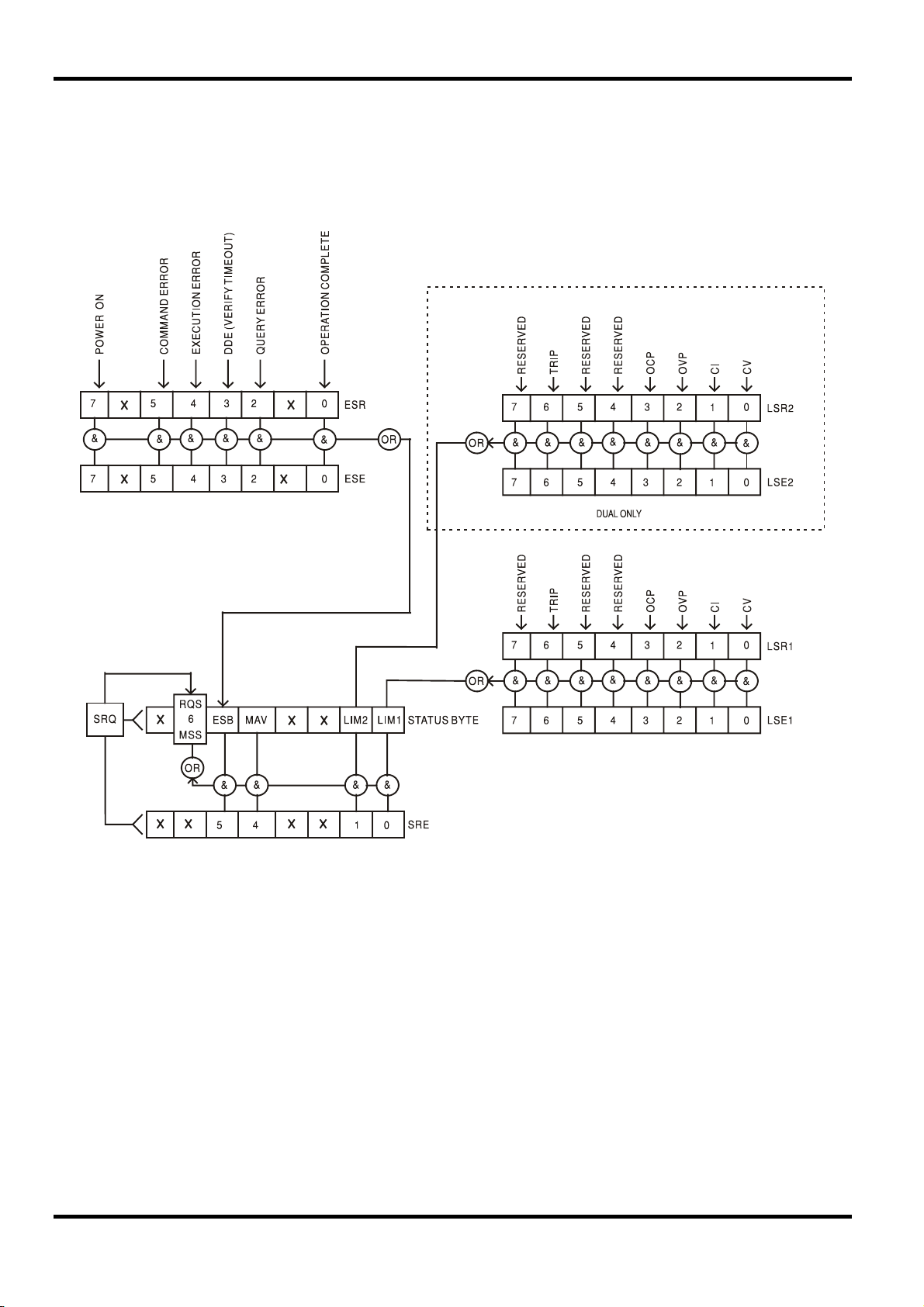
Status Model
32
Page 37

Power-on and Remote Operation Default Settings
The following instrument status values are set at power on:
Status Byte Register = 0
Service Request Enable Register † = 0
Standard Event Status Register = 128 (pon bit set)
Standard Event Status Enable Register † = 0
Execution Error Register = 0
Query Error Register = 0
Parallel Poll Enable Register † = 0
† Registers marked thus are specific to the GPIB section of the instrument and are of limited use
via other interfaces.
The instrument will be in local state with the front panel controls active (providing rear panel
switches CV and CC are set to Local.
The instrument parameters at power-on are the same as at last switch off with the exception of
the output status. By default this is always off at power on but the user may change this from the
front panel to the same at power on as at switch off, see Switching On and Power-on Conditions
paragraph in the Manual Operation section.
The *RST (reset) interface command resets the instrument to the Remote Operation Default
settings.
Remote Operation Default settings are:
V
=0.1V, I
out
=100mA, DeltaV=10mV, DeltaI=1mA, Vmin=3V, Vmax=5V, Tracking Ratio = 100%,
out
Lock cancelled, V-Span cancelled, 500mA Range cancelled, Meter Average cancelled, OVP &
OCP at 5% above instrument range maximums.
LAn Err message (10 seconds) for no LAN
connection found at power on is enabled. Configure page password on web server is reset to no
password.
Remote interface settings, stored set-ups, Vmin/Vmax values and Output state at power-on
setting are unchanged.
Mode and Sense settings are as determined by the front panel switches.
33
Page 38

RS232/USB Remote Command Format
RS232 input to the instrument is buffered in a 256 byte input queue which is filled, under interrupt,
in a manner transparent to all other instrument operations. The instrument will send XOFF when
approximately 200 characters are in the queue. XON will be sent when approximately 100 free
spaces become available in the queue after XOFF was sent. This queue contains raw (unparsed) data which is taken, by the parser, as required. Commands (and queries) are executed in
order and the parser will not start a new command until any previous command or query is
complete. RS232 responses to commands or queries are sent immediately; there is no output
queue.
USB input conforms with USB 2.0 Full Speed.
Commands must be sent as specified in the commands list and must be terminated with the
command terminator code 0AH (Line Feed, LF). Commands may be sent in groups with
individual commands separated from each other by the code 3BH (;). The group must be
terminated with command terminator 0AH (Line Feed, LF).
Responses from the instrument to the controller are sent as specified in the commands list. Each
response is terminated by a
CR) followed by 0AH (Line Feed, LF).
<WHITE SPACE> is defined as character codes 00H to 20H inclusive.
<WHITE SPACE> is ignored except in command identifiers. e.g. '*C LS' is not equivalent to '*CLS'.
The high bit of all characters is ignored.
The commands are case insensitive.
<RESPONSE MESSAGE TERMINATOR> which is 0DH (Carriage Return,
Remote Commands
GPIB Remote Command Formats
GPIB input to the instrument is buffered in a 256 byte input queue which is filled, under interrupt,
in a manner transparent to all other instrument operations. The queue contains raw (un-parsed)
data which is taken, by the parser, as required. Commands (and queries) are executed in order
and the parser will not start a new command until any previous command or query is complete.
There is no output queue which means that the response formatter will wait, indefinitely if
necessary, until the instrument is addressed to talk and the complete response message has
been sent, before the parser is allowed to start the next command in the input queue.
Commands are sent as
or more
<PROGRAM MESSAGE UNIT> elements separated by <PROGRAM MESSAGE UNIT SEPARATOR>
elements.
<PROGRAM MESSAGE UNIT> is any of the commands in the remote commands list.
A
<PROGRAM MESSAGE UNIT SEPARATOR> is the semi-colon character ';' (3BH).
A
<PROGRAM MESSAGES> are separated by <PROGRAM MESSAGE TERMINATOR> elements which may
be any of the following:
NL The new line character (0AH)
NL^END The new line character with the END message
^END The END message with the last character of the message
Responses from the instrument to the controller are sent as
<RESPONSE MESSAGE> consists of one <RESPONSE MESSAGE UNIT> followed by a <RESPONSE
MESSAGE TERMINATOR>
<RESPONSE MESSAGE TERMINATOR> is the new line character with the END message NL^END.
A
Each query produces a specific
the remote commands list.
<WHITE SPACE> is ignored except in command identifiers. e.g. '*C LS' is not equivalent to '*CLS'.
<WHITE SPACE> is defined as character codes 00H to 20H inclusive with the exception of the NL
character (0AH).
The high bit of all characters is ignored.
The commands are case insensitive.
<PROGRAM MESSAGES> by the controller, each message consisting of zero
.
<RESPONSE MESSAGE> which is listed along with the command in
<RESPONSE MESSAGES>. A
34
Page 39

Command List
This section lists all commands and queries implemented in this instrument.
Note that there are no dependent parameters, coupled parameters, overlapping commands,
expression program data elements or compound command program headers; each command is
completely executed before the next command is started. All commands are sequential and the
operation complete message is generated immediately after execution in all cases.
The following nomenclature is used:
<rmt> <RESPONSE MESSAGE TERMINATOR>
<nrf> A number in any format. e.g. 12, 12·00, 1·2 e1 and 120 e-1 are all accepted as the
number 12. Any number, when received, is converted to the required precision
consistent with the use then rounded to obtain the value of the command.
<nr1> A number with no fractional part, i.e. an integer.
<nr2> A number in fixed point format e.g. 11·52, 0·78 etc.
<n> The number of the output (1 or 2) or associated status register to which the
command relates. On the XEL30-3DP, ‘1’ is the Master (right-hand output) and ‘2’ is
the Slave (left-hand output).
The commands which begin with a
* are implemented as specified by IEEE Std 488.2 as
Common commands. All will function when used on the other interfaces but some may be of little
use.
Instrument Specific Commands
For commands specified as 'WITH VERIFY' the operation is completed when the parameter
being adjusted reaches the required value to within ±5% or ±10 counts, whichever is the greater.
If the value fails to settle within these limits within 5 seconds then the Verify Timeout bit (bit 3) is
set in the Standard Event Status Register and the operation is completed at the end of the
timeout period.
The Operation Complete bit (bit 0) in the Standard Event Status Register is only ever set by the
*OPC command. The *OPC (or the *OPC?) command can be used for device synchronization
due to the sequential nature of remote operations.
V<n> <nrf> Set output <n> to <nrf> Volts
V<n>V <nrf> Set output <n> to <nrf> Volts with verify
OVP<n> <nrf> Set output <n> over voltage protection trip point to <nrf> Volts
I<n> <nrf> Set output <n> current limit to <nrf> Amps
OCP<n> <nrf> Set output <n> over current protection trip point to <nrf> Amps
V<n>? Returns the set voltage of output <n>
The response is V <n> <nr2><rmt> where <nr2> is in Volts
I<n>? Returns the set current limit of output <n>
The response is I <n> <nr2><rmt> where <nr2> is in Amps
OVP<n>? Returns the voltage trip setting for output <n>
The response is VP<n> <nr2><rmt> where <nr2> is in Volts
OCP<n>? Returns the current trip setting for output <n>
The response is CP<n> <nr2><rmt> where <nr2> is in Amps
V<n>O? Returns the output readback voltage for output <n>
The response is <nr2>V<rmt> where <nr2> is in Volts
35
Page 40

I<n>O? Returns the output readback current for output <n>
The response is <nr2>A<rmt> where <nr2> is in Amps
IRANGE<n> <nrf> Sets the current range of output <n> to <nrf>, where <nrf> is 1 for Low (500mA)
range, 2 for High range. Output must be switched off before changing range.
IRANGE<n>? Report the current range for output <n>.
The response is <nr1><rmt>, where <nr1> is 1 for Low (500mA) range, 2 for
High range.
DELTAV<n> <nrf> Set the output <n> voltage step size to <nrf> Volts
DELTAI<n> <nrf> Set the output <n> current step size to <nrf> Amps
DELTAV<n>? Returns the output <n> voltage step size
The response is DELTAV<n> <nr2><rmt> where <nr2> is in Volts.
DELTAI<n>? Returns the output <n> current step size
The response is DELTAI<n> <nr2><rmt> where <nr2> is in Amps.
INCV<n> Increment the output <n> voltage by the step size set for output <n>
INCV<n>V Increment the output <n> voltage by the step size set for output <n> and verify.
DECV<n> Decrement the output <n> voltage by the step size set for output <n>
DECV<n>V Decrement the output <n> voltage by the step size set for output <n> and verify
INCI<n> Increment the output <n> current limit by the step size set for output <n>
DECI<n> decrement the output <n> current limit by the step size set for output <n>
OP<n> <nrf> set output <n> on/off where <nrf> has the following meaning: 0=OFF, 1=ON
OPALL <nrf> Simultaneously sets all outputs on/off where <nrf> has the following meaning:
0=ALL OFF, 1=ALL ON.
If OPALL sets all outputs ON then any that were already on will remain ON
If OPALL sets all outputs OFF then any that were already off will remain OFF
OP<n>? Returns output <n> on/off status.
The response is <nr1><rmt> where 1 = ON, 0 = OFF.
TRIPRST Attempt to clear all trip conditions.
LOCAL Go to local. This does not release any active interface lock so that the lock
remains with the selected interface when the next remote command is received.
IFLOCK Request interface lock. This command requests exclusive access control of the
instrument. The response is 1 if successful or –1 if the lock is unavailable either
because it is already in use or the user has disabled this interface from taking
control using the web interface
IFLOCK? Query the status of the interface lock. The return value is 1 if the lock is owned
by the requesting interfaced instance; 0 if there is no active lock or –1 if the lock
is unavailable either because it is already in use, or the user has disabled this
interface from taking control using the web interface.
IFUNLOCK Release the lock if possible. This command returns the value 0 if successful.
If this command is unsuccessful –1 is returned, 200 is placed in the Execution
Register and bit 4 of the Event Status Register is set indicating that there is no
authority to release the lock.
LSR<n>? Query and clear Limit Event Status Register <n>.
The response is <nr1><rmt>. See Status Reporting section for details.
36
Page 41

LSE<n> <nrf> Set the value of LSE<n>, Limit Event Status Enable Register <n>, to <nrf>
LSE<n>? Return the value of LSE<n>, Limit Event Status Enable Register <n> - response
is <nr1><rmt>
SAV<n> <nrf> Save the current set-up of output <n> to the set-up store specified by <nrf>
where <nrf> can be 0-9.
RCL<n> <nrf> Recall a set up for output <n> from the set-up store specified by <nrf> where
<nrf> can be 0-9.
RATIO <nrf> Set the ratio of output 2 (slave) to output 1 (master) in tracking mode to <nrf>,
where <nrf> is the ratio in percent (0 to 100).
RATIO? Query the ratio of output 2 (slave) to output 1 (master) in tracking mode. The
response is <nrf>, where <nrf> is the ratio in percent (0 to 100).
System and Status Commands
*CLS Clear Status. Clears the Status structure. This indirectly clears the Status Byte
Register.
EER?
Query and clear Execution Error Register. The response format is nr1<rmt>.
*ESE <nrf> Set the Standard Event Status Enable Register to the value of <nrf>
*ESE? Returns the value in the Standard Event Status Enable Register in <nr1> numeric
format. The syntax of the response is <nr1><rmt>
*ESR? Returns the value in the Standard Event Status Register in <nr1> numeric format.
The register is then cleared. The response is <nr1><rmt>. See Status Reporting
section for details.
*IST?
Returns ist local message as defined by IEEE Std. 488.2. The syntax of the
response is 0<rmt>, if the local message is false, or 1<rmt>, if the local message
is true.
*OPC Sets the Operation Complete bit (bit 0) in the Standard Event Status Register.
This will happen immediately the command is executed because of the
sequential nature of all operations.
*OPC? Query Operation Complete status. The response is always 1<rmt> and will be
available immediately the command is executed because all commands are
sequential.
*PRE <nrf> Set the Parallel Poll Enable Register to the value <nrf>.
*PRE? Returns the value in the Parallel Poll Enable Register in <nr1> numeric format.
The syntax of the response is <nr1><rmt>
QER? Query and clear Query Error Register. The response format is nr1<rmt>
*RST Resets the instrument to the remote control default settings with the exception of
all remote interface settings and stored set-ups. (see Remote Operation
Defaults paragraph in the Remote Interface Operation section)
*SRE <nrf> Set the Service Request Enable Register to <nrf>.
*SRE? Returns the value of the Service Request Enable Register in <nr1> numeric
format. The syntax of the response is<nr1><rmt>
*STB? Returns the value of the Status Byte Register in <nr1> numeric format. The
syntax of the response is<nr1><rmt>
*WAI Wait for Operation Complete true. As all commands are completely executed
before the next is started this command takes no additional action.
37
Page 42

Miscellaneous Commands
*IDN? Returns the instrument identification. The exact response is determined by the
instrument configuration and is of the form <NAME>,<model>,<Serial No.>,
<version><rmt> where <NAME> is the manufacturer's name, <model> defines
the type of instrument, Serial No. is the unique serial number and <version> is
the revision level of the software installed. The format of <version> is
X.xx – Y.yy where X.xx is the revision of the main instrument firmware and Y.yy
is the revision of the Interface board firmware. The Interface firmware is field
updateable by the user via the USB port.
ADDRESS? Returns the bus address of the instrument; This is the address used by GPIB, if
fitted, or may be used as a general identifier over the other interfaces.
CONFIG? Reports the operating mode set by the front panel MODE switch. The syntax of
the response is <nr1><rmt>, where <nr1> is 1 for single channel units and dual
units operating in parallel mode, 2 for dual units with both channels operating
independently and 0 for dual units in tracking mode.
DAMPING<n> <nrf> Set the current meter measurement averaging ( I
) of output <n> where <nrf>
AVG
has the following meaning: 0 = OFF, 1 = ON.
NOLANOK <nrf> Disables the LAn Err message for no LAN connection found at power on if
<nrf> is 1 and enables the message if <nrf> is 0.
*TST? The PSU has no self test capability and the response is always 0 <rmt>
*TRG The PSU has no trigger capability. The command is accepted but performs no
action.
Error Messages
Each error message has a number; only this number is reported via the remote control interfaces.
Error message numbers are not displayed but are placed in the Execution Error Register where
they can be read via the remote interfaces, see Status Reporting section.
38
Page 43

Routine calibration is carried out without opening the instrument. Allow a 10 minutes warm-up
before commencing calibration.
Equipment Required
A 5½ digit multimeter with better than 0.02% accuracy on dc volts and better than 0.06%
accuracy on dc current (to 5A). Alternatively use a precision shunt for current measurement.
Calibration
Calibration
Calibration mode is entered by holding down all three VOLTAGE SPAN keys (V
ENABLE) while the POWER switch is turned on (
indicator lamps will be lit, as a display test. When the VOLTAGE SPAN keys are released the
display will show the first calibration step and the ENABLE lamp will blink slowly.
In calibration mode V
each step the calibration must first be made 'active' by pressing the ENABLE key; the ENABLE
lamp blinks rapidly when calibration is active and the calibration value is adjusted using the MAIN
and FINE VOLTAGE controls. If ENABLE is not pressed at any step, calibration is not activated
at that step and the existing calibration value is retained when the step is exited.
During calibration the left-hand display shows the calibration value and the right-hand display
shows the step number. Some values are 5-digit, in which case the 5
hand digit of the right-hand display.
Some steps adjust values on the display and some adjust the output. When a step adjusts the
output, measured by the DMM, the left-hand display shows a number.
Calibration must be done in sequence. However, it is possible to pass through a step, without
making an adjustment, providing ENABLE is not pressed, see above.
The full procedure is detailed in the table. Steps 3 and 8 are model dependent; note that the
15V/5A model is calibrated at 3A to minimize errors.
Note that the CURRENT control must be at minimum for step 5.
The
change load message between steps 7 and 8 is the point at which the high current
range must be selected on the DMM.
steps forward to the next adjustment and V
max
l ). All the display segments and other
steps backwards. At
min
th
digit is shown in the left-
min
, V
max
and
The final step in the sequence (step 14) shows
stores the new calibration values and reboots the instrument in the normal operating mode. Until
this is done the new values are not stored permanently. Turning POWER off (
will retain all the old calibration values.
39
End. Pressing the ENABLE key for 2½ seconds
) at any point
(Calibration Table below)
Page 44

Step Settings Display Adjust for Load Detail
1. O/P off Cal count 0V ± 2mV DVM O/P off volts
2. 0V Cal count 0V ± 2mV DVM V DAC zero
3. Max V, 100mA Cal count 15/30/60V ± 2mV DVM V DAC scale
4. Max V, 100mA O/P volts Display = DVM DVM V metering scale
5. I pot at 0 I pot Display = 0 - I pot ADC zero
6. 2V, 0mA Cal count 0mA ± 0.2mA milli-ammeter High I DAC zero
7. 2V, 0mA O/P amps Display = milli-ammeter milli-ammeter High I metering zero
Change load
8. 2V, max I Cal count 1.5/3A ± 1mA Ammeter High I DAC scale
9. 2V, max I O/P amps Display = ammeter Ammeter High I metering scale
10. 2V, 0mA Cal count 0mA ± 0.02mA milli-ammeter Low I DAC zero
11. 2V, 0mA O/P amps Display = milli-ammeter milli-ammeter Low I metering zero
12. 2V, 500mA Cal count 500mA ± 0.1mA ammeter Low I DAC scale
13. 2V, 500mA O/P amps Display = ammeter ammeter Low I metering scale
14. O/P off ‘End’ - - Stores and exits
Maintenance
The Manufacturers or their agents overseas will provide a repair service for any unit developing a
fault. Where owners wish to undertake their own maintenance work, this should only be done by
skilled personnel in conjunction with the service manual which may be purchased directly from
the Manufacturers or their agents overseas.
Cleaning
If the instrument requires cleaning use a cloth that is only lightly dampened with water or a mild
detergent.
WARNING! TO AVOID ELECTRIC SHOCK, OR DAMAGE TO THE INSTRUMENT, NEVER
ALLOW WATER TO GET INSIDE THE CASE. TO AVOID DAMAGE TO THE CASE NEVER
CLEAN WITH SOLVENTS.
40
Page 45

Sécurité
Cet instrument est de Classe de sécurité 1 suivant la classification IEC et il a été construit pour
satisfaire aux impératifs EN61010-1 (Impératifs de sécurité pour le matériel électrique en vue de
mesure, commande et utilisation en laboratoire). Il s'agit d'un instrument d'installation Catégorie II
devant être exploité depuis une alimentation monophasée habituelle.
Cet instrument a été soumis à des essais conformément à EN61010-1 et il a été fourni en tout
état de sécurité. Ce manuel d'instructions contient des informations et avertissements qui doivent
être suivis par l'utilisateur afin d'assurer un fonctionnement de toute sécurité et de conserver
l'instrument dans un état de bonne sécurité.
Cet instrument a été conçu pour être utilisé en interne dans un environnement de pollution
Degré 2, plage de températures 5°C à 40°C, 20% - 80% HR (sans condensation). Il peut être
soumis de temps à autre à des températures comprises entre +5°C et –10°C sans dégradation
de sa sécurité. Ne pas l'utiliser lorsqu'il y a de la condensation.
Toute utilisation de cet instrument de manière non spécifiée par ces instructions risque d'affecter
la protection de sécurité conférée. Ne pas utiliser l'instrument à l'extérieur des tensions
d'alimentation nominales ou de la gamme des conditions ambiantes spécifiées.
AVERTISSEMENT! CET INSTRUMENT DOIT ETRE RELIE A LA TERRE
Toute interruption du conducteur de terre secteur à l'intérieur ou à l'extérieur de l'instrument
rendra l'instrument dangereux. Il est absolument interdit d'effectuer une interruption à dessein. Ne
pas utiliser de cordon de prolongation sans conducteur de protection, car ceci annulerait sa
capacité de protection.
Lorsque l'instrument est relié à son alimentation, il est possible que les bornes soient sous
tension et par suite, l'ouverture des couvercles ou la dépose de pièces (à l'exception de celles
auxquelles on peut accéder manuellement) risque de mettre à découvert des pièces sous
tension. Il faut débrancher toute source de tension éventuelle de l'appareil avant de l'ouvrir pour
effectuer des réglages, remplacements, travaux d'entretien ou de réparations. Les condensateurs
qui se trouvent dans le bloc d'alimentation risquent de rester chargés, même si le bloc
d'alimentation a été déconnecté de toutes les sources de tension, mais ils se déchargeront en
toute sécurité environ 1 minute après extinction de l'alimentation.
Eviter dans la mesure du possible d'effectuer des réglages, travaux de réparations ou d'entretien
lorsque l'instrument ouvert est branché à une source d'alimentation, mais si c'est absolument
nécessaire, seul un technicien compétent au courant des risques encourus doit effectuer ce
genre de travaux.
S'il est évident que l'instrument est défectueux, qu'il a été soumis à des dégâts mécaniques, à
une humidité excessive ou à une corrosion chimique, la protection de sécurité sera amoindrie et il
faut retirer l'appareil, afin qu'il ne soit pas utilisé, et le renvoyer en vue de vérifications et de
réparations.
Uniquement remplacer les fusibles par des fusibles d'intensité nominale requise et de type
spécifié. Il est interdit d'utiliser des fusibles bricolés et de court-circuiter des porte-fusibles.
Eviter de mouiller l'instrument lors de son nettoyage.
Les symboles suivants se trouvent sur l'instrument, ainsi que dans ce manuel.
ATTENTION - se référer à la documentation
ci-jointe; toute utilisation incorrecte risque
d'endommager l'appareil.
alimentation secteur OFF (éteinte)
courant alternatif (c.a.)
41
l
Borne de terre (masse)
alimentation secteur ON (allumée)
courant continu (c.c.)
Page 46

Tension d’alimentation sur secteur
Vérifier que la tension d’alimentation à l’arrière de l’appareil correspond à celle du secteur. S’il
s’avère nécessaire de changer de tension d’alimentation, procéder comme suit :
1. Assurez-vous que l'instrument est déconnecté du secteur.
2. Retirez les rivets-poussoirs en plastique de chaque côté du capot supérieur. Utilisez la lame
d’un petit tournevis pour libérer d'abord la tête du rivet, puis dégager complètement le corps
de la fixation. Retirez les deux vis du panneau arrière qui fixent le capot supérieur ; glissez
le capot vers l'arrière et soulevez-le.
3. Modifiez les connexions du transformateur (des deux transformateurs sur le modèle double)
conformément au schéma ci-dessous :
Installation
Fusible
4. Remontez l’appareil dans l’ordre inverse. Pour se conformer aux prescriptions des normes
de sécurité, la tension d’alimentation indiquée sur le panneau arrière doit être modifiée pour
indiquer clairement le nouveau réglage de tension.
Le fusible CA se trouve dans le compartiment à fusible dans la partie inférieure du connecteur
d'entrée IEC (appareil simple) ou dans des portes-fusibles séparés pour chaque canal (appareil
double).
Le type de fusible correct dans les cas mesure 20 x 5mm, 250V, avec retardement HBC et avec
la valeur nominale suivante:
230V Opération 115V Opération
BLEU MARRON BLEU MARRON
230V Opération : 1.6A (T)
115V Opération : 3.15A (T)
Remplacer les fusibles uniquement par des fusibles du courant nominal requis et du type
spécifié. Il est interdit d'utiliser des fusibles bricolés et de court-circuiter les porte-fusibles.
Cordon secteur
Brancher l’appareil sur l’alimentation secteur à l’aide du cordon secteur fourni. S’il s’avère
nécessaire d’utiliser une fiche secteur destinée à un autre type de prise murale, employer un
cordon secteur correctement dimensionné et homologué en l’équipant de la fiche murale voulue
et d’un connecteur IEC60320 C13 du côté de l’appareil.
Pour déterminer l’intensité nominale minimale du cordon en fonction de l’alimentation sur secteur
prévue, consulter les caractéristiques de puissance nominale figurant sur le matériel ou dans le
chapitre Spécifications.
Toute interruption du conducteur de terre de la prise secteur à l'intérieur ou à l'extérieur de
l’appareil rendra ce dernier dangereux. Il est interdit d'effectuer une coupure intentionnelle.
42
AVERTISSEMENT ! CET APPAREIL DOIT ETRE RELIÉ À LA TERRE.
Page 47

Montage
Cet appareil convient à la fois à l’utilisation sur établi et au montage en baie. Un kit de montage
en baie pour une baie de 19 pouces est disponible auprès du Fabricant ou de ses agents à
l’étranger
Ventilation
Le module d'alimentation est refroidi par un ventilateur intelligent multi-vitesses qui favorise la
convection verticale. Veillez à ne pas obturer les prises d'air sous l'appareil ni les orifices de
ventilation sur le dessus. En cas de montage en rack, laisser un espace adéquat au-dessus et
au-dessous de l’appareil et/ou utiliser un bloc ventilateur pour un refroidissement forcé.
.
43
Page 48
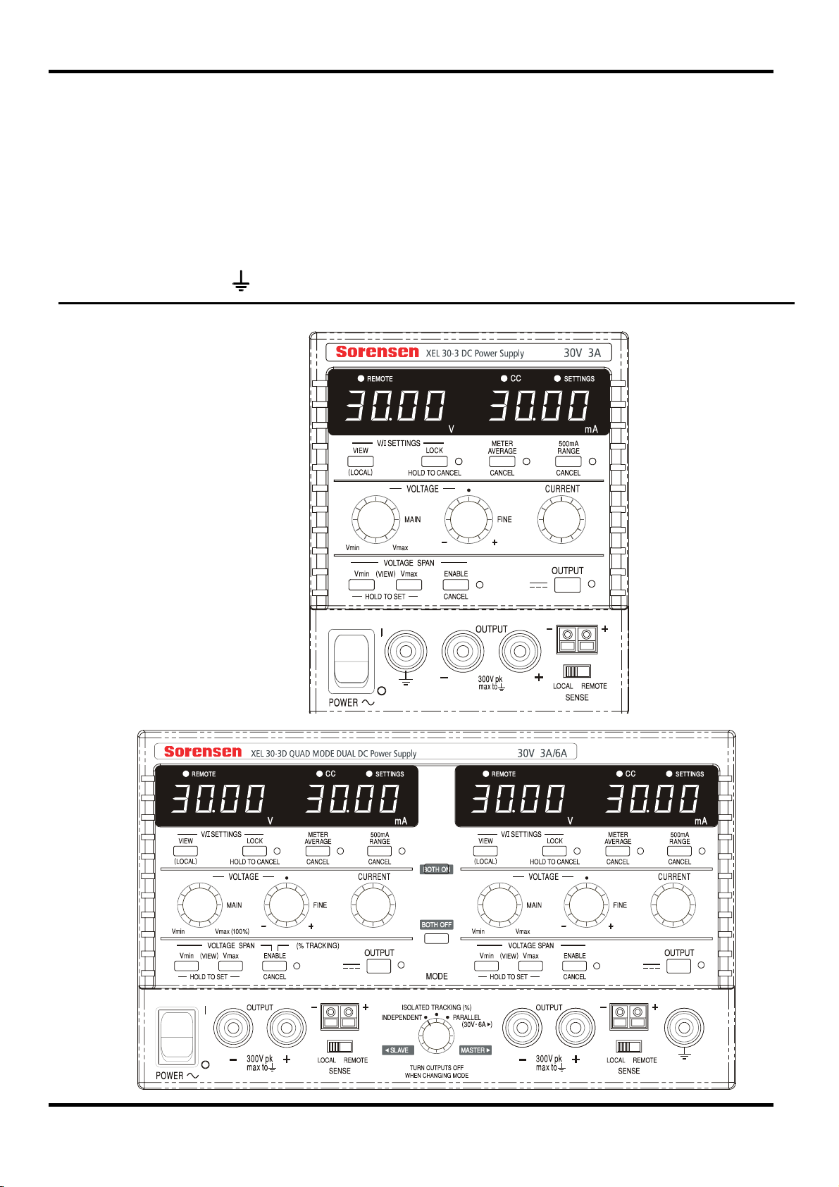
Connexions du panneau avant
La charge devra être connectée aux bornes positive (rouge) et négative (noire) marquées
OUTPUT (sortie). Les deux sont entièrement flottantes et l’une ou l’autre peuvent être
connectées à la masse.
Les connexions de détection à distance sur la charge, si nécessaire, sont réalisées à partir des
bornes positive (+) et négative (−) SENSE (détection). Placez le commutateur LOCAL/DISTANT
sur REMOTE (DISTANT) lorsque la détection distante est requise. Replacez-le sur LOCAL
lorsque la détection à distance n'est pas utilisée.
La borne marquée
AFFICHER LE
PANNEAU FRONTAL
est connectée au châssis et à la borne de mise à la terre.
Connexions
44
Page 49
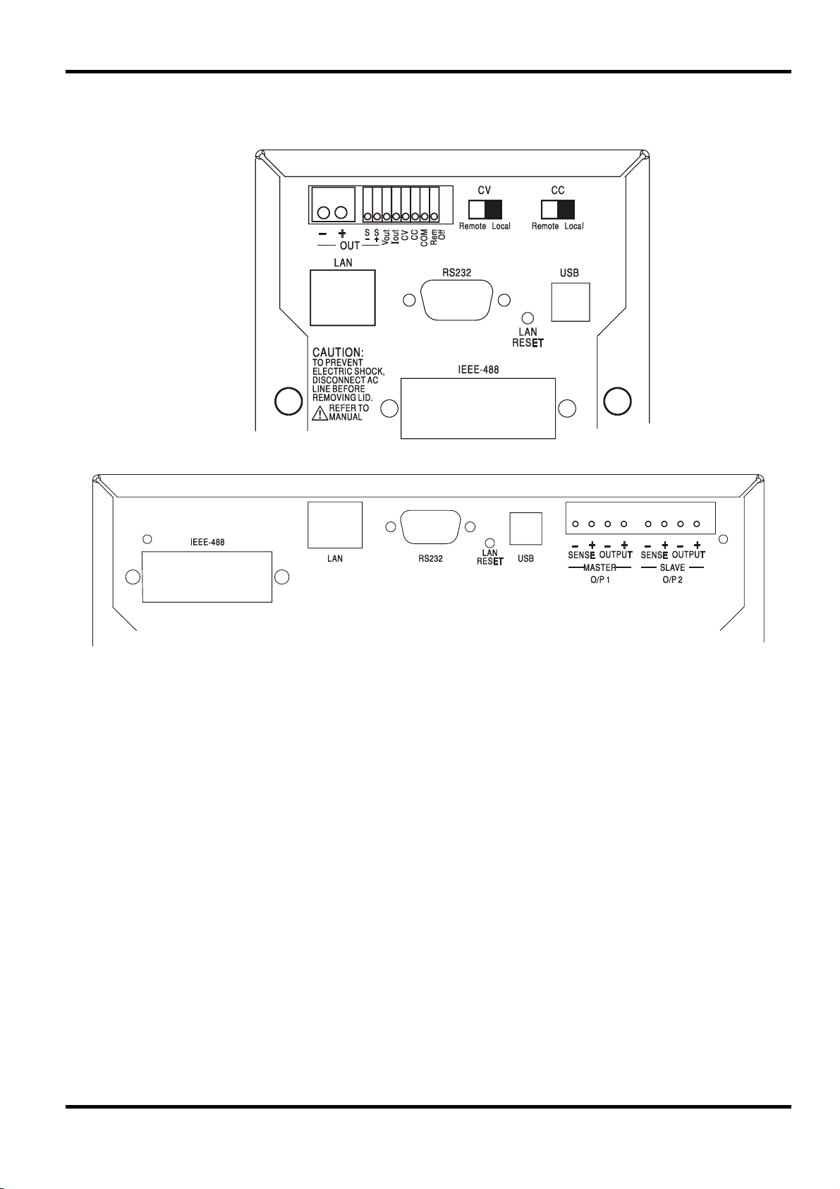
Connexions du panneau arrière
Les modèles non programmables n’ont pas de connexions au niveau du panneau arrière.
Les unites programmables des connexions du panneau arrière sont présentées ci-dessous :
Terminaux de sortie principale et de detection (ce sont tous des modèles programmables)
Les terminaux de sortie et de detection sont dupliqués sur le bloc du terminal du panneau arrière
et sont marques comme suit Output+, Output−, Sense + et Sense − ; les restrictions d’espace sur
les unités simples limitent les marquages à +, −, S+ et S− dans le groupe marqué OUTPUT
(SORTIE). Ces connexions sont mises en parallèle avec leurs équivalents de panneau avant.
Positionnez l’interrupteur LOCAL/REMOTE sur REMOTE (DISTANT) lorsque la détection à
distance est requise. Lorsque les terminaux de sortie du panneau arrière sont utilisés, l’utilisation
de la détection à distance est toujours recommandée afin de s'assurer que la régulation de sortie
reste dans le cadre des spécifications ; les connexions peuvent être effectuées sur les terminaux
de détection à distance avant ou arrière mais jamais sur les deux paires de terminaux
simultanément. Revenez en position LOCAL lorsque la détection à distance n’est pas utilisée.
Commande Distante Analogique (Uniquement les modèles programmables simples)
Les connexions CV et CC fournissent une commande analogique de la Tension de sortie et de la
Limite de courant lorsque les interrupteurs à glissière CV et CC sont positionnés sur Distant. La
graduation d’entrée peut être définie de manière indépendante, par des liens internes, de 0 à 5
Volts (le réglage d’usine par défaut) ou 0 à 10 Volts pour 0 à 100% de la sortie maximale. Le
signal de retour COMmun est référencé sur la sortie positive de l’alimentation électrique.
Le CV et CC peuvent être utilisés indépendamment l’un de l’autre ou ensemble.
45
Page 50

Remettez les interrupteurs à glissière CV et CC sur Local lorsque la commande distante
analogique n'est pas utilisée.
N’appliquez pas, entre les terminaux, de tensions externes supérieures au maximum pour
l’intervalle sélectionné (5V ou 10V).
Sortie analogique (Modèles programmables simples uniquement)
Les connexions V
OUT
et I
fournissent des sorties analogiques graduées respectivement pour la
OUT
tension de sortie définie et la limite de courant définie. La graduation est fixée sur 0 à 5 Volts
pour 0 à 100% de la sortie maximale. V
OUT
et I
sont toujours présentes sur les terminaux, que
OUT
l’instrument soit sous commande locale ou distante. Le signal de retour COMMUN est référencé
sur la sortie positive de l’alimentation électrique.
N’appliquez pas de tensions externes sur ces terminaux.
Distant Marche/Arrêt (Modèles programmables simples uniquement)
Une fermeture du commutateur ou un bas logique entre les connexions Rem off et COM éteindra
la sortie. Le signal de retour COM est référencé sur la sortie positive de l’alimentation électrique.
N’appliquez pas de tensions externes sur ces terminaux.
RS232 (Modèles XEL-P uniquement)
Connecteur-D femelle à 9−broches avec les connexions de broche indiquées ci-dessous. Il peut
être connecté au port d’un PC standard à l’aide d’un câble mâle-femelle 1:1 entièrement câblé
sans crossover de connexions.
Broche Nom Description
1 RI
Assertion passive (+V à travers 10kΩ)
2 TXD Données transmises depuis un instrument
3 RXD Données reçues dans l’instrument
4 CTS
5 GND Terre de signal
6 RTS
Assertion passive (+V à travers 10kΩ)
7 DSR Pas de connexion interne
8 DTR
9 CD Pas de connexion interne
La terre de signal est connectée à l’instrument au sol.
USB (Modèles XEL-P uniquement)
Le port USB est connecté à l’instrument au sol. Il se conforme à USB 2.0 (full speed) et accepte
un câble USB standard. Les fonctions plug-and-play de Windows doivent reconnaître
automatiquement que l’instrument a été connecté. Si le pilote adéquat est introuvable, suivez les
invites à l’écran de Windows et installez les fichiers requis à partir du CD fourni.
46
Page 51

LAN (Modèles XEL-P uniquement)
L’interface LAN est conçue pour se conformer à LXI (eXtensions Lan pour l’Instrumentation)
version 1.2 ; l’instrument est compatible avec la Class C. La commande distante utilisant
l’interface LAN est possible grâce à l’utilisation du protocole TCP/IP Sockets. L’instrument
contient également un serveur web de base qui fournit des informations sur l’unité et permet sa
configuration. Dans la mesure où il est possible de faire des erreurs de configuration sur
l'interface LAN, ce qui l’empêcherait de communiquer avec l’instrument sur LAN, un mécanisme
d’Initialisation de la Configuration LAN (LCI) est fournie via un interrupteur encastré sur le
panneau arrière (marqué REINIT LAN) pour réinitialiser le réglage d’usine par défaut.
D’autres détails sont donnés dans le chapitre Utilisation Distante. Pour plus d’informations sur
les normes LXI, veuillez consulter www.lxistandard.org/home
GPIB (option d’usine sur les modèles XEL-P uniquement)
Les terres de signal GPIB sont connectées à l’instrument au sol. Les sous-ensembles
implémentés sont les suivants :
SH1 AH1 T6 TE0 L4 LE0 SR1 RL2 PP1 DC1 DT0 C0 E2
L’adresse GPIB est définie depuis le panneau avant.
47
Page 52

Fonctionnement manuel
Dans ce operating manuel, les touches du panneau avant, les commandes et les prises sont
indiquées en majuscules, par exemple CURRENT, OUTPUT, LOCK. Les messages affichés sur
les voyants DEL à 7 segments sont affichés dans une police différente, par exemple
oFF, OtP trip
décrites ensemble à la fin de ce chapitre.
Conditions de mise en marche et de mise sous tension
L’interrupteur d’alimentation (POWER) se trouve en bas à gauche du panneau avant. Lorsque
l'interrupteur d'alimentation est activé (
version du microprogramme avant d'afficher les Volts et Ampères.
Pour les modèles XEL-P programmables, la sequence d’affichage par défaut à l’allumage est
différente : le mètre de droite indique brièvement la révision du progiciel de l’instrument suivie par
la révision du progiciel de l’interface (
n’affiche les Volts et Ampères. Si, après quelques secondes, aucune connexion au LAN
physique n’est détectée, l’créan de l’appareil clignotera entre la tension normale et les valeurs en
cours et le message
qu’aucune connexion LAN à l’allumage n’est disponible est une exigence de conformité LXI
essentielle mais elle peut être désactivée par la commande 'NOLANOK 1' sur toute interface -
voir le paragraphe Erreur LAN dans la section Fonctionnement de l’Interface Distante, pour plus
de détails. Cette modification des paramètres d’allumage est conservée jusqu’à ce qu’elle soit
annulée par une commande 'NOLANOK 0' ou par l’utilisation de l’interrupteur LAN RESET du
panneau arrière afin de restaurer les paramètres LAN d’usine – voir le paragraphe LAN dans la
section Fonctionnement de l’Interface Distante.
Notez que les messages de l’écran n’affectent pas le fonctionnement de l’alimentation électrique
elle-même.
A la mise sous tension, le réglage par défaut en usine est desactive. Les tensions de sortie de
courant prédéfinies seront déterminées par les réglages de commande actuels et indiqués dans
l’écran. Tous les autres paramètres seront les mêmes que lors du dernier arrêt de l'appareil.
La répétition de cette opération rétablira le paramètre précédent. Notez que l'état de mise sous
tension des deux sorties du double module doit être réglé individuellement.
. Les fonctions supplémentaires du double instrument en mode quad sont
l ) le mètre de droite indique brièvement le numéro de
IF s’affiche sur le mètre de gauche) avant que l’écran
LAn Err, apparaîtra pendant les 10 secondes suivantes. L’indication
L’état de sortie dc à la mise sous tension peut être défini de manière à être
« always off » (toujours désactivé) ou « same as at last power off » (le
même qu'à la dernière mise hors tension). Le paramètre peut être modifié
comme suit. Tout en maintenant enfoncée la touche VIEW (Afficher),
appuyez sur la touche OUTPUT (sortie)
l’écran affiche d’abord le paramètre actuel pendant 1 seconde (
le paramètre par défaut en usine est toujours sélectionné) avant de faire
clignoter le nouveau paramètre pendant 2 secondes (
cas). Au bout de 2 secondes, le nouveau paramètre reste affiché en
permanence à l'écran et le changement est mis en oeuvre ; relâchez les
touches OUTPUT et VIEW.
turn
et maintenez-la enfoncée ;
OP OFF si
LAST Set dans ce
48
Page 53

Contrôle de la sortie
Configuration de la sortie
Une fois l'alimentation activée et la sortie désactivée, la tension de sortie et la limite de
courant peuvent être prédéfinis de manière précises à l'aide des commandes VOLTAGE et
CURRENT ; le lecteur de gauche indique la tension définie, alors que celui de droite affiche le
courant maximum défini et que l'indicateur SETTINGS (paramètres) est allumé.
Lorsque le commutateur de sortie est désactivé, l'indicateur OUTPUT s'allume ; le lecteur de
gauche indique maintenant la tension réelle et celui de droite affiche le courant de charge réel.
Pour changer la plage limite de courant, il faut désactiver la sortie; si la sortie est activée, le
message d'avertissement
clignote et la plage reste inchangée.
Tension continue
La tension de sortie est ajustée à l'aide des commandes VOLTAGE principale et affinée ; la
commande CURRENT définit le courant maximum qui peut être fourni.
La limite supérieure de la commande CURRENT peut alterner
entre le maximum pour ce modèle et 500 mA avec des
pressions alternatives sur la touche 500 mA RANGE afin
d'affiner le réglage de la limite de courant et de la résolution de
mesure (de 0,1 mA à 500 mA) ; l'indicateur placé à côté de la
touche s'allume lorsque la plage 500 mA est sélectionnée.
turn oFF apparaît brièvement à l'écran, l'indicateur OUTPUT
Courant continu
Si la résistance à la charge est suffisamment basse pour qu'à la tension de sortie définie, un
courant supérieur au paramètre limite puisse circuler, le module d'alimentation passe
automatiquement en fonctionnement de courant continu. La sortie de courant est ajustée par la
commande CURRENT et les commandes VOLTAGE permettent de régler la tension maximale
pouvant être générée.
L'indicateur CC s'allume pour indiquer le mode de courant continu.
Sortie d’intensité instantanée
La commande de limite d’intensité peut être réglée pour limiter l’intensité de sortie continue à des
niveaux descendant jusqu’à 1mA (0,1 mA sur une plage de 500 mA). Cependant, communément
à tous les générateurs de précision d’établi, un condensateur est connecté sur la sortie pour
conserver la stabilité et une bonne réponse aux défauts transitoires. Ce condensateur se charge
sur la tension de sortie et le chargement de la sortie produira une impulsion d’intensité à la
décharge du condensateur, ce qui ne dépend pas du réglage de limite d’intensité.
Moyenne actuelle du mètre
Appuyez de nouveau sur la touche pour CANCEL (annuler) la moyenne du mètre et revenir à la
constante de temps standard de 20 ms.
Pour réduire les sautillements avec des courants de charge
variant rapidement, il est possible de sélectionner une
constante d'une durée de 2 secondes en appuyant sur la
touche METER AVERAGE ; l'indicateur situé à côté de la
touche s'allume lorsque la moyenne du mètre est
sélectionnée.
49
Page 54
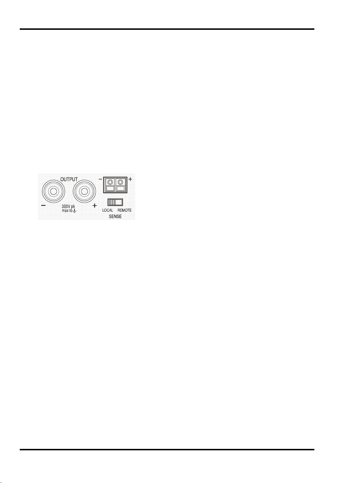
Économie
Le module d'alimentation minimise la dissipation en utilisant une pré-régulation électronique afin
de conserver une tension maximale faible pour les condensateurs de sortie. En outre, pour
optimiser le fonctionnement à des niveaux extrêmes de tension d'entrée et de puissance de
sortie CC, le transformateur secondaire est intelligemment remplacé par un relais. L'hystérésis
est utilisée au point de seuil pour empêcher un basculement inutile lorsque la sortie est définie à
ce niveau environ. En dehors d'un « clic audible », l'utilisateur ignorera que le relais s'est activé ;
cela ne perturbera pas la sortie. Les modèles programmables utilisent des transformateurs
spéciaux qui ne nécessitent pas de changement de prise de relais.
Connexion à la charge
La charge devra être connectée aux bornes OUTPUT positive (rouge) et négative (noire). Les
deux sont entièrement flottantes et l’une ou l’autre peuvent être connectées à la masse.
Détection à distance
L'unité possède une impédance de sortie très faible, mais elle est inévitablement augmentée par
la résistance des fils de connexion. A hautes intensités, ceci peut se traduire par des différences
significatives entre la tension source indiquée et la tension réelle de la charge (deux fils de
raccordement de 2mΩ chuteront de 0,2V à 5 Ampères, par exemple).
Pour éviter les problèmes d'instabilité et de réponse transitoire, il convient d'assurer un bon
couplage entre chaque fil de sortie et de détection. Pour ce faire, on peut torsader les fils
ensemble ou utiliser des câbles à protection coaxiale (détection par le fil interne). Un
condensateur électrolytique placé directement sur le point de connexion de la charge peut
également s’avérer avantageux.
Ce problème peut être minimisé en utilisant des fils de
raccordement courts et épais, mais lorsque cela s’avère
nécessaire, on peut le surmonter complètement en utilisant la
fonction de détection à distance. Ceci nécessite de connecter
les bornes de détection à la sortie sur la charge plutôt que sur
la source ; insérer les fils dans les bornes à ressort SENSE
(détection) et les connecter directement à la charge. Basculez
le commutateur LOCAL/REMOTE sur REMOTE.
La chute de tension dans chaque fil de sortie ne doit pas dépasser 0,5 Volts.
Replacez le commutateur LOCAL/REMOTE sur LOCAL lorsque la détection à distance n'est pas
utilisée.
Connexion de sortie et détection à distance sur les modèles programmables
Tous les modèles programmables sont équipés de terminaux de Sortie et de Détection en double
sur le panneau arrière, pratiques lorsque les instruments sont utilisés dans une armoire. Lorsque
les terminaux de sortie du panneau arrière sont utilisés, l’utilisation de la détection à distance est
toujours recommandée afin de s’assurer que la régulation de sortie demeure dans les
spécifications ; les connexions peuvent être faites sur les terminaux de détection distante avant
ou arrière, mais jamais sur les deux paires de terminaux simultanément. Connectez les
terminaux de Détection à la charge en suivant les directives ci-dessus, et réglez le commutateur
LOCAL/REMOTE (LOCAL/DISTANT) sur REMOTE (DISTANT).
Si les terminaux de Sortie du panneau arrière sont utilisés dans détection à distance, veillez à ce
que le commutateur du panneau avant soit réglé sur LOCAL. La régulation sera un peu
dégradée lorsque la détection est utilisée en raison d’une petite baisse de tension
supplémentaire dans le câblage aux terminaux arrière.
50
Page 55
Connexion en Série ou en Parallèle avec d’Autres Sorties
Les sorties du générateur sont entièrement flottantes et peuvent être utilisées en série avec
d’autres générateurs pour produire des tensions hautes CC allant jusqu’à 300 V CC.
La tension maximale admise entre toute borne et la terre (
AVERTISSEMENT ! De telles tensions sont excessivement dangereuses et un grand soin devra
être apporté à la protection des bornes pour une telle utilisation. En aucun cas on ne devra
toucher les bornes de sortie lorsque le générateur est allumé pour une telle utilisation. Tous les
branchements aux bornes doivent être établis avec tous les appareils hors tension.
Il convient de noter que le générateur ne peut que produire du courant et non en absorber, ainsi
les générateurs ne peuvent être connectés en série en anti-phase.
L’appareil peut être connecté en parallèle avec d’autres pour produire des courants plus forts.
Lorsque plusieurs appareils sont connectés en parallèle, la tension de sortie sera égale à celle du
générateur ayant le plus grand réglage de sortie, jusqu’à ce que le courant consommé dépasse
son réglage de limite d’intensité, moment auquel la sortie tombera au réglage le plus élevé
suivant, et ainsi de suite. En mode d’intensité constante, les appareils peuvent être connectés en
parallèle pour fournir une intensité égale à la somme des réglages de limite d’intensité.
Protection
La sortie dispose d'une protection intrinsèque contre les court-circuits et est protégée contre les
tensions inverses par une diode ; le courant continu inverse ne doit pas dépasser 3 ampères,
même si les pointes transitoires peuvent être nettement plus élevées. Si la tension inverse
appliquée peut produire plus de courant que la limite définie et que la sortie est activée, la sortie
passera au niveau limite du courant (l'indicateur CC clignotera) et son affichage présentera la
tension inverse sur la diode de protection ; si la sortie est désactivée, seul l'indicateur CC
clignotera.
Comme tous les modules d'alimentation à terminaison unique et régulés en série, l'unité ne peut
pas collecter le courant provenant d'une source externe. Si une tension supérieure à la tension
de sortie définie de l'unité est appliquée à partir d'une source externe, le régulateur interne se
désactivera et aucun courant ne circulera ; si la sortie est activée, le lecteur de tension lira la
tension appliquée. Cela ne produira aucun dommage à condition que la tension appliquée ne
dépasse pas la tension de sortie maximale du module d'alimentation de plus de 20 Volts.
La sortie (OUTPUT) étant désactivée, la charge reste connectée à la phase de sortie du module
d'alimentation ; la tension de sortie est simplement définie sur zéro. Ne pas appliquer aux bornes
du module d'alimentation de tensions externes dépassant de plus de 20 V la tension de sortie
nominale, même lorsque la sortie est désactivée, car cela pourrait endommager l'appareil.
) est de 300 VCC
Protection contre les dépassements de température
Un capteur interne détecte les dépassements de température liés à une obturation du flux d'air,
une défaillance du ventilateur ou une autre défaillance d'un circuit. Un dépassement de
température désactive la sortie, l'indicateur OUTPUT clignote et l'écran affiche le message OtP
triP. Une fois que la cause du dépassement de température a été éliminée et que l'instrument
est refroidi, l'indicateur de sortie s'éteint, mais le message OtP triP reste présent. Une
pression sur la touche OUTPUT modifie l'affichage et indique la tension et le courant prédéfinis
(l'indicateur SETTINGS s'allume), mais la sortie reste désactivée ; une deuxième pression active
normalement la sortie.
En cas de pression sur la touche OUTPUT pendant que l'instrument est toujours en dépassement
de température (l'indicateur OUTPUT clignote), le message OtP triP est remplacé par la
tension et le courant prédéfinis (l'indicateur SETTINGS s'allume), mais la sortie reste désactivée ;
chaque pression suivante sur la touche OUTPUT fait apparaître brièvement le message OtP
triP mais la sortie reste désactivée jusqu'à ce que la condition de dépassement de
température soit terminée.
51
Page 56
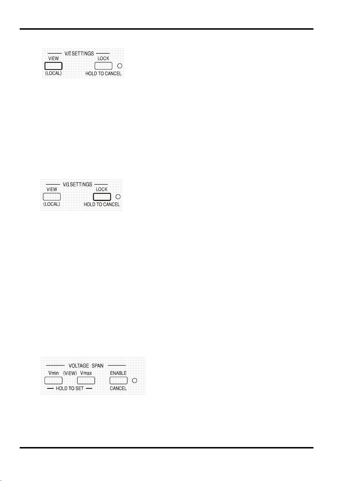
Affichage des paramètres
Verrouillage des paramètres
Une pression sur la touche LOCK verrouille numériquement la limite de tension et de courant
définie. Les paramètres sont stockés avec une précision supérieure à 1 chiffre. Les ajustements
suivants des commandes VOLTAGE et CURRENT seront sans effet.
Comme l'annulation de LOCK provoque un changement des paramètres de sortie si la position
des commandes VOLTAGE et CURRENT a été modifiée, des rappels d’avertissement sont
donnés avant l’annulation du LOCK.
Appuyer et maintenir la to4uche enfoncée pour annuler LOCK.
Si la sortie est désactivée (l’état sûr), l’écran fait clignoter les paramètres « non verrouillés » deux
fois avant l'application du changement ; l’indicateur LOCK s'éteint.
Le relâchement de la touche LOCK à tout moment pendant que l'écran clignote interrompra
l’annulation du LOCK.
Les limites de tension et de courant définies sont toujours affichées
lorsque la sortie est désactivée, mais peuvent aussi être lues après
une pression sur la touche VIEW ; l'indicateur SETTINGS s'allume
en cas de pression sur la touche VIEW.
Si la sortie est toujours activée, le message OP on (sortie activée)
clignote deux fois à l'écran, suivi par le clignotement des nouveaux
paramètres « non verrouillés » pendant 2 à 3 secondes (un
clignotement lent, puis plus rapide), avant que le changement ne
soit finalement appliqué, l'indicateur LOCK s'éteint une fois le
changemlent effectué.
Une tentative de changement de la plage limite de courant (voir la section Configuration de la
Sortie) ou des limites extrêmes de la tension (voir la section Ecart de tension) avec LOCK activé
n'est pas admise ; si une telle tentative est faite, le message Unloc apparaît brièvement et
l'indicateur LOCK clignote également. Si la sortie est également activée lorsque ces actions sont
tentées, le message turn oFF apparaît en premier lieu à l'écran (accompagné de l'indicateur de
sortie qui clignote), suivi du message Unloc (avec l'indicateur LOCK clignotant).
Le statut LOCK au démarrage est le même qu‘à la dernière mise hors tension.
Utilisation de l'écart de tension
La fonction VOLTAGE SPAN (V-Span) (écart de tension) permet à l'utilisateur de redéfinir les
valeurs d'extrémité des commandes VOLTAGE de telle manière que les commandes fonctionnent
dans une plage de tension spécifique, plus étroite. Cela présente non seulement l'avantage de se
protéger contre l'application accidentelle de la charge des tensions en dehors de la plage, mais
fournit également un contrôle analogique haute résolution sur la plage de tension spécifiée en
utilisant l'intégralité de la rotation à 300 ° des commandes de tension.
Dans la mesure où l'activation de V-Span modifiera toujours la tension de sortie, cette option ne
peut être activée ou annulée que si la sortie est désactivée ; toute tentative d'activation ou
d’annulation de V-Span alors que la sortie est affichée provoque l'apparition rapide du message
turn oFF invitant l'utilisateur à désactiver la sortie.
V-Span est activé ou désactivé à l’aide de la touche
ENABLE. L’indicateur ENABLE est allumé lorsque
V-Span est sélectionné. La valeur d'usine par défaut est
V
= 3V, V
min
max
= 5V
52
Page 57

Pour définir de nouvelles valeurs pour V
min
ou V
la fonction V-Span doit être désactivée
max
(annulée).
La limite inférieure de tension est définie à l'aide des commandes MAIN et FINE VOLTAGE qui
permettent de choisir exactement la valeur requise ; la touche V
est alors maintenue enfoncée
min
jusqu'à ce que l'affichage de gauche (V) cesse de clignoter et que l'affichage de droite (mA)
indique Set. Le paramètre peut être affiché à tout moment par une brève pression (<1 seconde)
sur la touche V
manière à l'aide des commandesVOLTAGE et de la touche V
. La limite de tension supérieure est définie et affichée exactement de la même
min
.
max
Les limites peuvent être réglées dans n'importe quel ordre et sur n'importe quelle valeur située
dans la plage de sortie de l'instrument, mais V-Span peut uniquement être activé à l'aide de la
touche ENABLE si V
max
≥ (V
+ 0,1V) ; si cette condition n'est pas remplie, le message Set
min
Err apparaît brièvement et la fonction V-Span n'est pas mise en œuvre.
Lorsque V-Span est activé, la plage de la commande MAIN VOLTAGE est exactement de V
V
quand la commande FINE est réglée à son point intermédiaire, marqué sur le panneau par
max
. La commande FINE elle-même peut être utilisée pour régler plus précisément la valeur sur
un •
±1% (de l'écart de tension).
Le statut V-Span au démarrage est le même qu‘à la dernière mise hors tension.
Mode Control (Controle de mode) du Quad-Mode Dual
Les quatre modes de fonctionnement du Quad-Mode Dual sont
décrits ci-dessous ; on modifie ce mode à l’aide de la molette
MODE. Pour éviter l’application accidentelle de tensions
imprévues aux circuits connectés aux sorties, le changement
de mode provoque toujours une désactivation des deux sorties.
min
à
Toutefois, on ne peut pas garantir qu'il n'y aura jamais de courants transitoires indésirables lors
du changement de mode, et il est donc recommandé que
désactivées avant tout changement de mode
Independent
Définissez le MODE sur INDEPENDENT. Les deux sorties sont alors entièrement indépendantes
et isolées électriquement, chacune pouvant être définie comme décrit dans la section
précédente, Contrôle de sortie.
Il n’est pas possible de basculer du mode Independent au mode Tracking avec LOCK défini sur la
sortie Slave. Le message Un loc apparaît dans l’écran Slave et la fonction LOCK doit être
désactivée (en mode Independent) avant que les modes Tracking puissent être utilisés.
Voir aussi le paragraphe Paramètres Slave conservés.
Isolated Tracking
Définissez le MODE sur ISOLATED TRACKING. Les deux sorties restent isolées électriquement,
mais les contrôles de Voltage de la sortie Master présentent une tension identique sur la sortie
Slave. Les commandes Current du Slave restent indépendant, notamment la plage 500 mA et les
fonctions Meter Average.
L’isolation électrique permet aux deux sorties d’être connectés afin de fournir, par exemple, les
tensions de sortie de polarité opposée ou des tensions identiques connectées à différentes
références du système (par ex. la prise de terre numérique et la prise de terre analogique).
les deux sorties soient toujours
.
53
Page 58

Les fonctions LOCK et VOLTAGE SPAN du Master fonctionnent exactement comme décrit
précédemment et, comme la tension de sortie du Slave suit celle du Master, elles contrôlent
également la fonction de sortie Slave. Notez que seule la tension de sortie du Slave est
verrouillée lorsque le LOCK Master est utilisé ; les commandes de courant du Slave, y compris
les fonctions 500mA Range et Meter Average, restent indépendantes.
La touche LOCK de la sortie Slave est ignorée et si on l’utilise, elle fait apparaître temporairement
le message In trac sur l’écran Slave à titre de rappel.
Il est possible de basculer du mode Tracking au mode Independent alors que le LOCK est
toujours activé sur le Master. Les paramètres Master (sortie de droite) restent « verrouillés » mais
les paramètres de la sortie de gauche ne sont pas verrouillés.
Les touches Voltage Span du Slave ont une fonction différente en mode Tracking, voir la section
suivante.
Isolated Ratio (%) Tracking
Définissez le MODE sur ISOLATED TRACKING.
L’instrument fonctionne comme décrit ci-dessus pour le mode Tracking mais la tension du Slave
peut être définie sur un pourcentage (de 0 % à 101 %) de la tension Master à l’aide des
commandes Slave Voltage. Le ratio est ensuite maintenu lorsque la tension du Master varie.
Une nouvelle pression sur la touche ENABLE ramène le Slave au mode Tracking standard
(indicateur ENABLE éteint).
Le Ratio Tracking ne peut être activé ou désactivé que lorsque la sortie est désactivée. Si la
sortie est activée, l'écran affiche brièvement le message turn oFF lorsque vous appuyez sur
ENABLE et le changement n’est pas appliqué.
Chaque fois que le mode Ratio Tracking est activé, l’écran Slave affiche temporairement Pcnt
on avant d'afficher à nouveau la tension de sortie qui est maintenant définie.
Le Ratio Tracking est activé par une pression
sur la touche ENABLE dans la section
VOLTAGE SPAN du Slave (indicateur
ENABLE activé)
Parallel
La valeur de pourcentage peut être affichée à tout moment en appuyant sur la touche V
V
de la sortie Slave. Lorsque vous maintenez l’une de ces deux touches enfoncées, l'écran du
max
min
ou
Slave affiche le paramètre de pourcentage sous la forme 90.0 Pcnt et les contrôles Slave
Voltage permettent de définir le pourcentage de ratio requis. Le pourcentage de ratio peut être
défini avant l’activation de Ratio Tracking (indicateur ENABLE éteint).
Les fonctions LOCK et VOLTAGE SPAN du Master fonctionnent exactement comme décrit
précédemment. Toutefois, lorsque Ratio Tracking est activé, les commandes de Slave Voltage
peuvent toujours être utilisées pour régler le pourcentage de ratio de la tension du Slave, même
si la tension du Master est verrouillée. Le statut du mode Ratio Tracking (appariement du rapport)
au démarrage est le même qu’à la dernière mise hors service. Voir aussi le paragraphe
Paramètres du Slave conservés.
L’interrupteur MODE est défini sur PARALLEL. L’instrument fonctionne véritablement en mode
parallèle, avec toute la puissance disponible à partir de la sortie Master qui peut ensuite fournir
jusqu’à 6 ampères. La sortie Slave est désactivée et ses écrans sont éteints.
En mode Parallel, la valeur de la limite actuelle est doublée pour le même paramètre de contrôle
de limite Current, y compris la plage 500 mA, qui devient 1000 mA au maximum ; à titre
d'avertissement, la première fois que le mode Parallel est sélectionné, l'écran actuel clignote
deux fois avant d'afficher en continu la nouvelle limite. De même, le courant s'affiche deux fois
lorsque le mode bascule de Parallel à Tracking, pour vous avertir du fait que la limite de courant
de sortie du Master est maintenant réduite de moitié.
54
Page 59

Les fonctions LOCK et VOLTAGE SPAN du Master opèrent exactement comme décrit
précédemment. Il est possible de basculer du mode Parallel au mode Tracking (et vice versa)
alors que LOCK est toujours réglé sur le Master ; les commandes Voltage et Current du Master
restent en LOCK, comme décrit précédemment. Toutefois, la limite de courant réelle définie du
Master doublera encore (en passant du mode Tracking au mode Parallel), ou sera réduite de
moitié (en passant du mode Parallel au mode Tracking), même si LOCK est défini, mais
l'affichage du courant clignote pour vous avertir de ce changement.
Paramètres du Slave conservés
Si V-Span est activé sur la sortie Slave en mode INDEPENDENT, il est désactivé lorsque le mode
TRACKING estsélectionné, mais réactivé ,lorsque le mode INDEPENDENT est à nouveau
sélectionné.
Si Ratio (%) Tracking est activé sur la sortie Slave en mode TRACKING, il est désactivé lorsque
INDEPENDENT ou PARALLEL est sélectionné, mais réactivé lorsque le mode TRACKING est à
nouveau sélectionné.
Commande Marche/Arrêt de la sortie simultanée
Les touches Both On / Both Off s’ajoutent aux interrupteurs OUTPUT
individuels et permettent d’activer ou de désactiver les deux sorties de
manière synchronisée d’une simple pression.
Les touches Both On / Both Off fonctionnent dans les quatre modes de
configuration.
55
Page 60

Commande Analogique Distante
(Modèles programmables simples
La commande analogique distante de la tension et du courant de sortie est possible à l’aide de
plusieurs tensions de commande externe appliquées respectivement entre les entrées CV et
COM ou CC et COM du panneau arrière.
Les tensions de commande de sortie analogique V
« maître » peuvent être utilisées pour contrôler une unité « esclave » via les entrées respectives
CV et CC de l’esclave.
Commande de tension analogique
La commande de tension analogique distante est obtenue par le réglage du commutateur CV du
panneau arrière du Remote (Distant) et en appliquant une tension de programmation entre les
entrées CV et COM.
Les commandes de VOLTAGE (TENSION) du panneau avant sont désactivées lorsque Remote
est réglé sur le commutateur CV. Réglez le commutateur sur Local pour retourner à la
commande sur le panneau avant.
La graduation de la tension d’entrée par défaut est de 0V à 5V pour 0 à 100% de la tension
nominale de sortie. La graduation de la tension d’entrée peut être modifiée pour être de 0V à
10V en supprimant un lien de raccourci interne. Déconnectez l’instrument de la source CA et
enlevez le cache comme décrit dans la section Installation. Consultez la vue de dessus de
l’instrument présentée dans le dessin, et supprimez le lien de raccourci long dans la position LK1.
out
uniquement)
et I
d’une unité agissant comme
out
La CV distante peut être utilisée avec le CC Local ou Distant.
Commande de courant analogique
La commande de courant constant analogique distant est obtenue par le réglage de l’interrupteur
CC du panneau arrière sur Remote (Distant), et par l’application d’une tension de programmation
entre les entrées CC et COM. La commande de courant analogique distant ne peut être utilisée
que sur l’intervalle de courant élevé, et non sur l’intervalle de 500mA.
La commande CURRENT (Courant) du panneau avant est désactivée lorsque le commutateur
CC est positionné sur Remote (Distant). Positionnez le commutateur sur Local pour rendre la
commande au panneau avant.
La graduation par défaut de la tension d’entrée est de 0V à 5V pour 0 à 100% du courant nominal
maximal (intervalle élevé uniquement). La graduation de la tension d’entrée peut être modifiée
pour être de 0V à 10V en supprimant le lien de raccourci interne. Déconnectez l’instrument de la
source AC et enlevez le cache comme décrit dans la section Installation.
56
Page 61

Consultez la vue de haut de l’instrument présentée dans le dessin, et enlevez le lien de raccourci
long de l’emplacement LK3.
Le CC distant peut être utilisé avec la CV Locale ou Distante.
ATTENTION. N’appliquez pas de tensions de commande externes à l’entrée CV ou CC
supérieures au maximum pour l’intervalle d’entrée défini (5V ou 10V). Les entrées sont
protégées contre les tensions supérieures mais l’instrument tentera de fournir une tension ou un
courant de sortie supérieur à son rating maximal si la tension de commande dépasse la limite
d’intervalle, ce qui pourrait provoquer des dégâts. Si la situation persiste, OVP et/ou OCP
peuvent déclencher la mise hors tension de la sortie, voir la prochaine section.
OVP et OCP
L’OVP (protection contre la surtension) et l’OCP (protection contre la surintensité) sont
implémentées dans un firmware et ne peuvent être réglées et utilisées que sous la commande
distante via les interfaces RS232, USB, LAN (LXI) ou GPIB. Les résolutions de paramétrage
sont de 10mV de 1mA et les temps de réponse habituels sont de 500ms.
Cependant, en mode local, l’OVP et l’OCP sont encore actives mais se règlent automatiquement
par défaut à 105% de l’intervalle maximal de l’instrument. Cela fournit une protection d’arrêt très
utile en cas d’application prolongée d’une tension de commande de CV ou CC qui tente de définir
la sortie au-delà de l’intervalle maximal de 105%.
Considérations pratiques liées à l’utilisation de CV et CC
La stabilité des tensions de commande affecte directement la stabilité de la sortie. Tour bruit sur
les signaux de commande génèrera du bruit sur la sortie. Afin de minimiser le bruit sur la sortie,
connectez les tensions de commande aux entrées CV, CC et COM à l’aide de paires torsadées
ou écrantées (écrans reliés à la terre à une seule extrémité) et veillez à ce que les connexions
soient les plus courtes possibles.
Les diagrammes ci-dessous montrent les connexions pour la commande de Tension Constante
(CV) et de Courant Constant (CC) à l’aide d’une tension externe.
Commande de Tension Constante
Commande de Courant Constant
57
Page 62

Notez que lorsque la OUTPUT (SORTIE) est en marche, l’affichage de l’instrument affiche
toujours la tension et le courant de sortie réels, quelle que soit la source de commande active.
Cependant, lorsque la OUTPUT (SORTIE) est arrêtée, l’écran affichera la tension et le courant
prédéfinis par les commandes du panneau avant (ou l’interface numérique si elle est active) et
non les valeurs déterminées par les entrées CV et CC, même si elles ont été rendues actives
(CV et CC réglées sur Remote (Distant)). Pour éviter toute confusion, il convient de régler les
commandes du panneau avant au minimum lorsque la CV et le CC distants sont utilisés.
Tensions de commande de sortie analogique
Les tensions de commande de sortie analogique V
out
et I
sont générées à partir des tensions de
out
commande interne réelles, pour lesquelles la source active peut être les commandes du panneau
avant, l’interface numérique (RS232, USB, LAN ou GPIB) ou les entrées analogiques distantes
CV et CC. V
out
et I
sont graduées de manière à ce que 0 à 100% de la tension et du courant
out
nominaux de sortie (uniquement intervalle élevé) génère 0V à 5V sur les terminaux V
panneau arrière en ce qui concerne COM. COM est connecté à la sortie positive.
correspond toujours au courant défini, que la sortie soit ou non activée, mais V
I
out
lorsque la sortie est désactivée.
Fonctionnement parallèle dans une configuration Master-Slave (Maître-Esclave)
Un fonctionnement parallèle dans une configuration Master-Slave permet la réalisation de
courants de sortie supérieurs avec un partage de courant égal entre les unités et la commande
de la tension et du courant à partir d’une seule unité. Toutes les unités doivent être du même
type, c’est-à-dire, elles doivent avoir le même courant et tension nominaux de sortie. Le
diagramme présente trois unités connectées en parallèle. Pour un partage de courant égal,
chaque unité doit être connectée indépendamment à la charge avec des paires de câbles d’une
jauge et d’une longueur égales pour assurer des baisses de tension égales. Connectez V
du maître aux entrées CV et CC des esclaves (positionnez les commutateurs CV et CC sur
Remote(Distant)) comme indiqué.
Remarque : Ne faites pas de connexions entre les entrées COM des esclaves car elles sont déjà
reliées au maître via les connecteurs de sortie positive.
La tension et le courant du maître peuvent être réglés soit par les commandes du panneau avant,
soit par l’interface numérique, ou par une tension externe appliquée à ses propres entrées de
commande analogique CV et CC.
Fonctionnement parallèle dans une configuration Master-Slave (Maître-Esclave)
Notes:
1. Les unités peuvent être connectées pour la CV
(tension constante, le CC (courant constant) ou
les deux (tous deux affichés). Positionnez les
commutateurs CV et/ou CC de l'esclave sur
Remote (Distant).
2. Connectez les sorties en parallèle en utilisant
des longueurs de câble équivalentes à la charge.
3. Si la détection à distance est requise, utilisez
uniquement la détection à distance du maître à la
charge.
4. Pour un fonctionnement sous courant constant,
définissez le surdébit de tension requis sur le
maître.
et I
out
va sur 0V
out
out
out
du
et I
out
58
Page 63

En mode de tension constante, la tension sur la charge est celle définie sur l’unité maître par ses
commandes du panneau avant, via l’interface numérique ou par l’entrée de commande distante
CV analogique. La limite de courant pour le système (à savoir le courant en mode de courant
constant) correspond à la limite de courant définie sur le x n maître, où n est le nombre total
d’unités connectées en parallèle.
Remarque : Dans la mesure où les entrées de commande distante analogique ne sont pas
isolées (COM est connecté au terminal de sortie positive), il n’est pas possible d’utiliser la
commande distante analogique avec les instruments connectés en série.
Distance désactivée
Une fermeture de commutateur ou un bas logique entre les entrées Rem Off (Distance
désactivée) et COM du panneau arrière, désactivera à distance la sortie si elle était auparavant
activée ; la lampe OUTPUT (SORTIE) du panneau avant s’éteindra également. L’ouverture du
commutateur entre Rem Off et COM réactivera la sortie.
59
Page 64

Fonctionnement de l’Interface Distante
L’instrument peut être contrôlé à distance via ses interfaces RS232, USB, LAN ou GPIB (en
option). La commande distante analogique est décrite dans la section précédente.
La télécommande USB fonctionne de la même manière que décrit pour un appareil RS232 mais
par l’intermédiaire du connecteur USB. Le logiciel fourni avec l’appareil configure l’ordinateur de
contrôle pour traiter la connexion USB comme un port COM virtuel. Le logiciel d’application de
l’ordinateur peut ensuite communiquer avec l’appareil via le port COM.
L’interface LAN est conçue pour être conforme à LXI (Lan eXtensions for Instrumentation) version
1.2 ; l’instrument est compatible avec la Class C. La commande distante utilisant l’interface LAN
est possible à l’aide du protocole TCP/IP Sockets. L’instrument contient également un serveur
web de base qui fournit des informations sur l’unité, lui permettant ainsi d’être configurée à partir
d’un navigateur internet. Une simple commande de ligne de commande du navigateur est
également possible.
L’instrument est fourni avec des interfaces RS232, USB, et LAN en standard ; GPIB est en
option. Toutes les interfaces sont, par défaut, actives à tout moment (un exigence LXI) mais
l’accès à des interfaces spécifiques peut être limité à l’aide des options de configuration sur les
pages web.
Verrouillage de l’Interface
Toutes les interfaces sont actives à tout moment ; cela élimine la nécessité de sélectionner
l’interface active et représente également une exigence de LXI. Afin de réduire le risque que
l’instrument soit, par inadvertance, sous le contrôle de deux interfaces en même temps, un
simple mécanisme de verrouillage et de déverrouillage est fourni dans le jeu d’instructions. Le
verrou est automatiquement débloqué lorsqu’il est possible dé détecter une déconnexion et
lorsque le bouton local est enfoncé. L’accès aux interfaces peut également être restreint à l’aide
des pages web.
Toute interface peut nécessiter d’avoir la commande exclusive de l’instrument en envoyant une
commande “IFLOCK”. Le verrou ne peut être débloqué que par l’envoi d’une commande
“IFUNLOCK” depuis l’instance de l’interface qui a actuellement le verrou et peut être demandé à
partir de toute interface par l’envoi d’une commande “IFLOCK?”. La réponse à l’une de ces
commandes sera “-1” si le verrou est détenu par une autre instance d’interface, “0” si l’interface
est libre et “1” si le verrou est détenu par l’instance d’interface effectuant la requête. L’envoi de
toute commande depuis une interface sans droits de commande qui tente de modifier le statut de
l’instrument définira un bit 4 du Event Status Register Standard et placera 200 dans le Execution
Error Register pour indiquer que les droits sont insuffisants pour l’action requise.
Remarque : il est également possible de configurer les droits d’une interface spécifique soit en
« lecture seule » soit en « pas d’accès » à partir de l’interface de la page internet.
Sélection d’adresse
La capacité d’adresse de l’instrument n’est strictement requise que par l’interface GPIB.
Toutefois, il est possible d’utiliser la commande ADDRESS? Sur l’une quelconque des interfaces,
afin d’identifier facilement l’instrument qui est contrôlé par un port COM spécifique (pour RS232
ou USB) ou TCP socket (for LAN). Notez que l’interface LAN possède également une fonction
« Identifier » distincte, accessible depuis les pages internet de l’instrument, et qui fait clignoter
l’écran de l’instrument, jusqu’à ce que la fonction soit annulée.
60
L’adresse est définie sur le panneau avant de l’instrument, comme suit. Démarrer en ayant
l'appareil hors tension, avec toutes les touches Lock, Meter Average et Current Range enfoncées
(la sortie SLAVE sur double uniquement), puis mettre l'appareil sous tension. L'écran affiche
Addr dans l'affiche des Volts et nn dans l'affichage des mA, où nn est le paramètre actuel
(par défaut
Addr 11).
Page 65

L'adresse peut être décrémentée et incrémentée avec les touches Meter Average et Current
Range respectivement dans la plage allant de 1 à 31 inclus (pas 0), avec 'wrap-round' (mettre à
cheval). L'adresse est confirmée et le processus terminé en maintenant la touche Lock enfoncée.
L'écran affiche
l'affichage normal des Volts et des mA une fois que la nouvelle adresse a été acceptée.
L’adresse peut également être définie depuis les pages internet de l’instrument.
Set et la nouvelle adresse pendant environ 2 secondes, puis retourne à
Fonctionnement Distant/Local
A l’allumage, l’instrument sera à l’état local avec l’indicateur REMOTE (DISTANT) désactivé.
Dans cet état, toutes les opérations du panneau avant sont possibles. Lorsque l’instrument est
adressé pour écouter et qu’une commande est reçue, l’état distant est saisi et l’indicateur
REMOTE (DISTANT) sera activé. Dans cet état, le panneau avant est verrouillé et seules les
commandes distantes seront traitées. Les paramétrages V/I, le paramétrage Meter Average, et
(les) l’état(s) Current Range et de sortie demeurent inchangés mais LOCK et V-Span sont
désactivés s’ils étaient activés. Les valeurs Vmin et Vmax sont conservées. Les paramètres
MODE (modèles XDL-P uniquement) et Sense (Détection) sont définis par les commutateurs du
panneau avant. L’instrument peut être remis à l’état local en appuyant sur la touche LOCAL ;
cependant, l’effet de cette action restera jusqu’à ce que l’instrument soit réadressé ou reçoit un
autre caractère de l’interface, lorsque l’état distant sera de nouveau saisi. Revenir à l’état Local
par cette action, ou par l’utilisation de la commande LOCAL, laissera les paramètres V/I aux
dernières valeurs définies à distance, avec les Lock Settings (Paramètres de verrou) activés, et
laissera la(les) sortie(s) dans leur état actuel.
Interface RS232
Connecteur d'interface RS232
Le connecteur d'interface série type D 9 voies se trouve sur le panneau arrière de l’appareil.
Son brochage est indiqué ci-dessous :
Broche Nom Description
1 RI Avec assertion passive (+V à 10kΩ)
2 TXD Données transmises à partir de l’appareil
3 RXD Données reçues par l’appareil
4 CTS
5 GND Terre de signal
6
7 DSR Pas de connexion interne
8 DTR
9 CD Pas de connexion interne
Connexions RS232
L’interface RS232 doit être connectée à un port de PC standard à l’aide d’un câble complet 1:1
mâle-femelle sans connexion croisée. Il est également possible de connecter uniquement les
broches 2, 3 et 5 au PC, mais avec des liaisons dans l le connecteur côté PC entre les broches
1, 4 et 6 et entre les broches 7 et 8, reportez-vous au schéma.
RTS
Avec assertion passive (+V à 10kΩ)
61
Page 66

Le Débit de Baud pour cet instrument est fixé à 9600 ; les autres paramètres sont fixés comme
suit :
Bits de départ : 1 Parité : Aucune
Bits de données : 8 Bits d’arrêt : 1
Jeu de caractères RS232
En raison de la nécessité d’un protocole XON/XOFF, il n’est possible de transmettre que des
données en code ASCII ; les blocs binaires ne sont pas admis. Le bit 7 des codes ASCII est
ignoré, c'est-à-dire qu’il est supposé bas. Aucune distinction n’est faite entre les majuscules et les
minuscules pour les mnémoniques de commande et on peut les mélanger librement. Les codes
ASCII inférieurs à 20H (espace) ne sont pas utilisés. Dans ce manuel, 20H signifie 20 en
hexadécimal. L’unité enverra XOFF lorsqu’il y a 50 bits libres restants et XON lorsque celui-ci
augmente à 100 bits.
Interface USB
L’interface USB est un port COM virtuel pouvant être contrôlé par un PC comme s’il était un
appareil RS232. L’appareil est fourni avec un CD qui contient un fichier .inf pour les pilotes
standard de Microsoft sous Windows 2000, XP, Vista et Windows 7; l'assistant d’installation
installe le pilote (32 bits ou 64 bits) qui convient sur le système d'exploitation du PC. Toutes les
mises à jour sont disponibles via le site Internet de AMETEK, www.programmablepower.com .
L’installation du pilote d’interface s’effectue en connectant l’instrument à un PC via un câble USB
standard. Les fonctions ’Plug & Play’ de Windows devraient automatiquement reconnaître l’ajout
d’un nouveau matériel sur l’interface USB et si c’est la première fois que la connexion est établie,
elles demanderont l’emplacement d’un pilote convenable. A condition que les invites standard de
Windows soient correctement suivies, Windows installera le pilote approprié et établira un port
COM virtuel dans le PC. Le numéro du nouveau port COM dépendra du nombre de ports COM
coexistant dans le PC. Le port COM virtuel peut être piloté par les applications Windows
exactement de la même manière qu’un port standard, sauf que le réglage de la vitesse de
transmission du port COM virtuel est ignoré.
62
Le pilote restera installé sur le PC de sorte que l’établissement d’un port COM virtuel sera
effectué automatiquement chaque fois que l’appareil sera à l’avenir connecté au PC via l’USB.
Des ports COM supplémentaires sont créés pour chaque appareil supplémentaire connecté au
PC via l’USB. Chaque appareil reçoit un port COM virtuel différent la première fois qu'il est
connecté et ce même port COM sera utilisé chaque fois qu’un appareil est reconnecté ; le logiciel
PC utilise le code unique intégré dans chaque appareil pour le lier au même port COM virtuel,
quelque soit le port USB utilisé.
Page 67

Il est également possible d’utiliser la commande ADDRESS? pour identifier facilement
l’instrument qui est contrôlé par un port COM spécifique. Bien que la capacité d’adressage soit
ignorée dans le fonctionnement de l’USB, l’adresse peut encore être définie et utilisée comme
identifiant ; définissez chaque instrument connecté à l’USB à une adresse différente et envoyez
la commande ADDRESS? depuis chaque port COM virtuel afin de confirmer l’instrument qui est
connecté à ce port.
LAN
L’interface LAN est conçue pour être compatible avec le LXI version standard 1.2 et contient les
interfaces et protocoles décrits ci-dessous. Dans la mesure où il est possible de faire des erreurs
de configuration sur l’interface LAN, ce qui l’empêche de communiquer avec l’instrument sur
LAN, un mécanisme de LAN Configuration Initialise (LCI) (Initialiser la Configuration LAN) est
fourni via un commutateur encastré sur le panneau arrière afin de réinitialiser l’unité aux
paramètres d’usine par défaut. Le paramétrage par défaut concerne les instruments afin de
tenter d’obtenir des paramètres via le DHCP, s’il est disponible ou, si le DHCP dépasse le délai
d’attente (au bout de 30 secondes), via Auto-IP. Dans le cas très improbable où une adresse IP
Auto est introuvable, une adresse IP statique de 192.168.0.100 est attribuée. La réinitialisation
du LAN supprime toute protection par mot de passe.
Pour plus d’informations sur les normes LXI, veuillez consulter www.lxistandard.org/home
Connexion LAN
Pour utiliser l’interface LAN, l’adresse IP de l’unité doit être connue. Un outil LXI Discovery Tool
sur le CD-ROM fourni peut être utilisé pour afficher les adresses IP (et autres informations
associées) de tous les appareils connectés conformes au protocole de détection VXI-11. Cet
outil est une application PC Windows qui doit être installée et exécutée sur le PC de contrôle
avec l’unité connectée soit directement au connecteur réseau du PC soit par l'intermédiaire d'un
routeur. La connexion via un routeur est recommandée car l’attribution d’une adresse IP est
nettement plus rapide ; la connexion directement au PC commencera à attribuer une adresse IP
après seulement 30 secondes de dépassement de délai du DHCP. Le fait de double cliquer sur
toute entrée de la liste des appareils connectés ouvrira le navigateur web du PC et affichera la
page d'accueil de cet appareil.
Il existe également des outils pour la détection LAN compris dans le cadre du module National
Instruments Measurement and Automation Explorer package et l’application Agilent Vee.
Dès qu’elle sera mise sous tension, l’unité tentera d’obtenir les paramètres via le DHCP s’il est
disponible, ou, si le délai d’attente du DHCP est dépassé (30 secondes), via Auto-IP. Dans le
cas très improbable où une adresse IP Auto est introuvable, une adresse IP statique de
192.168.0.100 est attribuée. Si la connexion ne se fait toujours pas, l’instrument fera clignoter
LAn Err sur l‘écran, voir la section Erreur LAN pour plus de détails.
Serveur Web; Protection du mot de passé de configuration
L’unité contient un serveur web de base. Celui-ci fournit des informations sur l’instrument et lui
permet d’être configuré. La page Configurer peut être protégée par un mot de passe pour
empêcher toute modification non autorisée de la configuration du fonctionnement distant ; la
configuration par défaut est “pas de mot de passe”.
La page Configurer elle-même explique comment paramétrer le mot de passe. Celui-ci peut
contenir jusqu’à 15 caractères ; notez que le
mot de passe sera cependant réinitialisé à la valeur par défaut (pas de mot de passe) si
l’interrupteur LAN RESET du panneau arrière est utilisé pour réinitialiser tous les paramètres LAN
à leur valeur d’usine par défaut.
Les pages web ont également une fonction « identifier » qui permet à l’utilisateur d’envoyer une
commande d’identification à l’instrument qui entraîne le clignotement de son écran jusqu’à ce que
la commande soit annulée.
63
Nom de l’utilisateur doit être laissé vierge. Le
Page 68

Serveur ICMP Ping
L’unité contient un serveur ICMP permettant à l’instrument d’être « pingué » via son nom d’hôte
ou son adresse IP.
Protocole de Détection VXI-11
L’instrument a un support très limité de VXI-11, suffisant pour le protocole de détection et pas
plus.
L’instrument met en œuvre un mappeur de port Sun RPC sur le port 111 du TCP et le port 111 de
l’UDP comme défini dans RPC1183. Les appels pris en charge sont les suivants : NULL, GET
PORT et DUMP.
Sur le port 1024 du TCP, un protocole VXI-11 très simple est mis en œuvre et suffit uniquement
pour la détection d’instrument. Cela met en œuvre les appels suivants : CREATE LINK,
DEVICE_WRITE, DEVICE_READ et DESTROY_LINK.
Dès qu’un lien a été créé, tout ce qui est écrit sur l’appareil est ignoré et toute lecture depuis
l’appareil renvoit la chaîne d’identification qui serait attendue d’un “*IDN?” sous la forme
‘Manufacturer,Model,Serial No.,X.xx – Y.yy’
Par exemple
SORENSEN,XEL601P,279730,1.00 – 1.00
Où ‘X.xx’ est la révision du firmware principal et ‘Y.yy’ est la révision du firmware de l’interface.
Le firmware de l’interface est adaptable dans le champ utilisateur via le port USB.
Nom de ressource VISA
À cause du soutien limité pour le VXI-11(Discovery Protocol uniquement), on doit utiliser les
informations concernant son socket raw pour se référer à l’instrument lorsqu'il est utilisé dans des
progiciels qui communiquent par un nom de ressource VISA. Par exemple, un instrument à
l'adresse IP 192.168.1.100 doit normalement avoir un nom de ressource VISA
"TCPIP0::192.168.1.100::inst0::INSTR", mais pour cet instrument, le nom doit être modifié pour
lire "TCPIP0::192.168.1.100::9221::SOCKET", où 9221 est le port TCP utilisé par cet instrument
pour le contrôle et la surveillance ; voir ci-dessous.
URL du Documentation d’Identification XML
Comme cela est requis par la Norme LXI, l’instrument fournit un document d’identification XML
qui peut être requêté via un GET sur “http://<hostname>:80/lxi/identification” qui est conforme au
schéma LXI XSD (disponible sur http://www.lxistandard.org/InstrumentIdentification/1.0) et les
Normes de Schémas W3C XML ( http://www.w3.org/XML/Schema ). Ce document décrit
l’instrument.
Prises TCP
L’instrument utilise 2 prises sur le port 9221 TCP pour le contrôle et le suivi de l’instrument. Les
commandes de texte sont envoyées sur ce port comme défini dans les « Commandes distantes »
et toute réponse est renvoyée via le même port. Toute chaîne doit être constituée d’une ou
plusieurs commandes complètes. Les commandes peuvent être séparées par des points virgules
“;” ou sauts de ligne. Aucun terminator n’est requis puisque le cadre TCP contient des
commandes complètes, bien que les commandes puissent être envoyées avec un terminator si
on le souhaite (il sera ignoré). Chaque commande sur TCP se comporte comme si elle était
terminée avec un terminator de commande (ASCII caractère 0AH, saut de ligne).
Erreur LAN
Si une connexion LAN est effectuée mais qu’une erreur est détectée (par exemple, l’adresse IP
est la même que celle d’un autre appareil du réseau) alors, l’écran de l’instrument clignotera de
manière alternée, entre les valeurs de tension et de courant normales et LAn Err, jusqu’à ce
que l’erreur soit corrigée.
64
Page 69

Si une erreur LAN se produit ; vérifiez et corrigez la configuration de l’instrument ; un mécanisme
LAN Configuration Initialise (LCI) (Initialisation de la Configuration LAN) est fourni via un
commutateur encastré sur le panneau arrière (marqué LAN RESET(REINITIALISATION LAN))
afin de réinitialiser l’unité sur le paramétrage d’usine par défaut. Le paramétrage par défaut sert
à ce que l’instrument tente d’obtenir les paramètres via le DHCP, s’il est disponible, ou si le
DHCP dépasse le délai d’attente (30 secondes), via Auto-IP. Dans le cas très improbable où une
adresse IP Auto est introuvable, une adresse IP statique de 192.168.0.100 est attribuée.
L’écran clignotera également entre les valeurs normales et
phusique n’est détectée à l’allumage, mais il s’arrêtera de clignoter au bout de 10 secondes.
Pour désactiver ce message à chaque allumage, émettez la commande 'NOLANOK 1' sur toute
interface. Pour réactiver le message à l’allumage, émettez la commande 'NOLANOK 0 ' ou
utilisez l’interrupteur LAN RESET encastré dans le panneau arrière afin de réinitialiser tous les
paramètres LAN à leurs valeurs d’usine, voir l’introduction de la section LAN.
Interface GPIB
Lorsque l'interface GPIB est montée, le connecteur 24 voies GPIB se trouve sur le panneau
arrière de l'instrument. Les connexions des broches sont spécifiées à la norme IEEE 488.1-1987
et l'instrument doit être conforme aux normes IEEE 488.1-1987 et IEEE 488.2-1987.
Sous-ensembles GPIB
Cet instrument contient les sous-ensembles IEEE 488.1 suivants:
Source Handshake (établissement de liaison avec l'émission) SH1
Acceptor Handshake (acceptation de liaison) AH1
Talker (émetteur) T6
Listener (récepteur) L4
Service Request (demande de service) SR1
Remote Local (à distance local) RL2
Parallel Poll (scrutation parallèle) PP1
Device Clear (initialisation dispositif) DC1
Device Trigger (déclenchement dispositif) DT0
Controller (contrôleur) C0
Electrical Interface (interface électrique) E2
LAn Err si aucune connexion LAN
Query Error Register (Traitement des erreurs GPIB norme IEEE 488.2 – registre d’erreurs
d’interrogation)
L'IEEE 488.2 UNTERMINATED error (erreur non terminée IEEE 488.2) (mode d'émission, mais rien
à émettre) est traitée de la manière suivante. Si l'instrument est en mode d'émission, que le
formateur de réponse est inactif et que la file d'attente d'entrée est vide,
UNTERMINATED error est
généré. Ceci entraîne le positionnement du bit Query Error (erreur d'interrogation) dans le
Standard Event Status Register (registre d'état d'événement standard) et une valeur de 3 dans le
Query Error Register (registre d'erreurs d'interrogation) et la réinitialisation de l'analyseur
syntaxique. Se reporter à la section Rapport d'état pour plus d'informations.
L'IEEE 488.2
INTERRUPTED error (erreur interrompue IEEE 488.2) est traitée de la manière
suivante. Si le formateur de réponse attend de transmettre un message de réponse et qu'un
<PROGRAM MESSAGE TERMINATOR> (terminaison de message de programme) a été lu par
l'analyseur syntaxique ou que la file d'attente d'entrée contient plus d'un message END (fin), ceci
indique que l'instrument a été
INTERRUPTED (interrompu) qu'une erreur est générée. Ceci entraîne
le positionnement du bit Query Error dans le Standard Event Status Register et une valeur de 1
dans le Query Error Register et la réinitialisation du formateur de réponse, ce qui vide la file
d'attente de sortie. L'analyseur syntaxique commence alors à analyser le
UNIT>
(unité de message de programme) suivant de la file d'attente d'entrée. Se reporter à la
<PROGRAM MESSAGE
section Rapport d'état pour plus d'informations.
65
Page 70

L'IEEE 488.2 DEADLOCK error (erreur de blocage fatal IEEE 488.2) est traitée de la manière
suivante. Si le formateur de réponse attend de transmettre un message de réponse et que la file
d'entrée devient pleine, l'instrument passe à l'état
générée. Ceci entraîne le positionnement du bit Query Error dans le Standard Event Status
Register et une valeur de 2 dans le Query Error Register et la réinitialisation du formateur de
réponse, ce qui vide la file d'attente de sortie. L'analyseur syntaxique commence alors à analyser
le
<PROGRAM MESSAGE UNIT> suivant de la file d'attente d'entrée. Se reporter à la section Rapport
d'état pour plus d'informations.
Scrutation parallèle GPIB
Cet instrument fournit des capacités de scrutation parallèle complètes. Le Parallel Poll Enable
Register (registre d'activation de scrutation parallèle) est réglé pour spécifier les bits du Status
Byte Register (registre d'octets d'état) qui doivent être utilisés pour constituer le message local
Le Parallel Poll Enable Register est réglé par la commande *PRE <nrf> puis lu par la commande
*PRE?. La valeur du Parallel Poll Enable Register est liée en montage ET avec le Status Byte
Register; si le résultat est zéro, la valeur de
DEADLOCK (blocage fatal) et une erreur est
ist.
ist est 0, sinon la valeur de ist est 1.
Il faut également configurer l'instrument afin que la valeur de
ist puisse retourner au contrôleur
lors d'une opération de scrutation parallèle. L'instrument est configuré par le contrôleur qui
transmet une commande Parallel Poll Configure (PPC) (configuration scrutation parallèle) suivie
d'une commande Parallel Poll Enable (PPE) (activation scrutation parallèle). Les bits de la
commande PPE sont indiqués ci-dessous:
bit 7 = X sans effet
bit 6 = 1
bit 5 = 1 activation scrutation parallèle
bit 4 = 0
bit 3 = Détection détection du bit de réponse; 0 = bas, 1 = haut
bit 2 = ?
bit 1 = ? position de bit de la réponse
bit 0 = ?
Exemple. Pour retourner le bit RQS (bit 6 du Status Byte Register) au niveau 1 à l'état vrai et au niveau
0 à l'état faux à la position de bit 1 en réponse à une scrutation parallèle, transmettre les
commandes suivantes :
*PRE 64<pmt>, puis PPC suivi de 69H (PPE)
La réponse de scrutation parallèle de l’instrument sera alors 00H si RQS est 0 et 01H si RQS
est 1.
Pendant la réponse de scrutation parallèle, les lignes d'interface DIO sont terminées de manière
résistive (terminaison passive). Ceci permet à plusieurs dispositifs de partager la même position
de bit de réponse en configuration de câblage en ET ou OU, se reporter à IEEE 488.1 pour plus
d'informations.
Reporting de statut
Un modèle d’erreur et de statut distinct est conservé pour chaque instance d’interface ; une
instance d’interface est définie comme une connexion potentielle. USB, RS232 et GPIB sont
intrinsèquement des connexions uniques et par conséquent représentent chacun une instance
d’interface. Le LAN, cependant, permet plusieurs connexions simultanées et par conséquent
représente plusieurs instances d’interface. Deux instances d’interface sont attribuées aux deux
interfaces de TCP socket et une instance supplémentaire est attribuée à l’interface de la page
web. Le fait d’avoir un modèle séparé pour chaque instance d’interface garantit que les données
ne sont pas perdues alors que de nombreuses commandes, telles que ‘*ESR?’, effacent le
contenu à la lecture.
Le statut de l’erreur est conservé à l’aide d’un ensemble de registres ; ils sont décrits dans les
paragraphes et présentés dans le Modèle de Statut à la fin de cette section.
66
Page 71

Standard Event Status & Standard Event Status Enable Registers (registres d'état d'événement
standard et d'activation d'état d'événement standard)
Ces deux registres sont mis en oeuvre comme exigé par la norme IEEE 488.2.
Tous les bits définis dans le Standard Event Status Register qui correspondent aux bits
positionnés dans le Standard Event Status Enable Register entraîneront le positionnement du bit
ESB dans le Status Byte Register.
Le Standard Event Status Register est lu, puis vidé par la commande *ESR?. Le Standard Event
Status Enable Register est réglé par la commande *ESE <nrf> et lu par la commande *ESE?.
C’est un champ de bit dans lequel chaque bit a la signification suivante.
Bit 7: Mise sous tension. Définie lorsque l’alimentation est d’abord appliquée à l’instrument.
Bit 6: Requête utilisateur (non utilisé).
Bit 5: Erreur de commande. Défini lorsqu’une erreur de type de syntaxe est détectée dans
une commande depuis le bus. L’analyseur est réinitialisé et l’analyse continue au
prochain bit dans le courant d’entrée
Bit 4: Erreur d’exécution. Défini lorsqu’une erreur est rencontrée pendant une tentative
d’exécuter une commande complètement analysée. Le numéro d’erreur approprié sera
indiqué dans le Execution Error Register, voir la section Messages d’erreur
Bit 3: Vérifier les erreurs de délais dépassés. Défini lorsqu’un paramètre est réglé avec
« vérifier » spécifié et que la valeur n’est pas atteinte dans les 5 secondes, par exemple
la tension de sortie est ralentie par un important condensateur sur la sortie.
Bit 2: Erreur de requête. Régler quand une demande se produit. Le numéro approprié de
l'erreur est signalé dans le Query Error Register (Registre des erreurs de requête) ; voir
la section du Query Error Register.
Bit 1: Non utilisé.
Bit 0: Opération terminée : Défini en réponse à la commande ‘*OPC’.
Execution Error Register
Ce registre contient un nombre représentant la dernière erreur rencontrée sur l’interface actuelle.
Le Execution Error Register est lu et effacé à l’aide de la commande ‘EER?’. A l’allumage, ce
registre est défini sur 0 pour toutes les instances d’interface.
Les messages d’erreur ont la signification suivante :
0: Aucune erreur rencontrée
1-9: Erreur de matériel interne détectée.
100: Erreur d’intervalle. La valeur numérique envoyée n’est pas autorisée. Cela inclut des
nombres qui sont trop grands ou trop petits pour le paramètre défini et les non entiers
envoyés lorsque seuls les nombres entiers sont autorisés.
101: Un rappel des données de paramétrage a été demandé mais le magasin spécifié
contient des données corrompues. Cela indique un défaut matériel ou une corruption
de données temporaire, qui peut être corrigé en réécrivant les données dans le
magasin.
102: Un rappel des données de paramétrage a été demandé mais le magasin spécifié ne
contient aucune donnée.
103: Tentez de lire ou écrire une commande sur la deuxième sortie lorsqu’elle n’est pas
disponible. En règle générale, cela se produira si on tente de programmer la deuxième
sortie sur les instruments à canal unique ou sur un instrument à deux canaux qui est
défini en mode parallèle.
104 La commande n’est pas valide lorsque la sortie est activée. Ceci est habituellement
engendré par l’utilisation de la commande 'IRANGE <n>' sans avoir préalablement
désactivé la sortie.
200: Lecture seule : Une tentative a été faite de modifier les paramètres de l’instrument,
depuis une interface sans droits d’écriture, voir la section Verrouillage de l’Interface.
67
Page 72

Limit Event Status Register (registre d’état d’événement limite) et Limit Event Status Enable
Register (registre d’activation d’état d’événement limite)
Il existe pour les alimentations électriques de sortie unique, un Event Status Register Limite ;
pour les alimentations électriques doubles (sauf en cas de fonctionnement en mode parallèle) ils
sont deux. Ils doivent être lus et effacés à l’aide de ‘LSR1?’ et ‘LSR2?’ respectivement.
A l’allumage, ces registres sont définis sur 0 puis définis immédiatement pour indiquer la nouvelle
limite de statut.
Tout bit réglé dans un Limit Event Status Register correspondant au bit réglé dans le Limit Event
Status Enable Register qui l’accompagne provoque le réglage du bit LIM1 ou LIM2 dans le Status
Byte Register.
Bit 7 : Réservé à une utilisation future
Bit 6 : Défini lorsqu’un déclenchement s’est produit qui ne peut être réinitialisé qu’à partir du
panneau avant ou en supprimant et en réappliquant l’électricité CA.
Bit 5: Réservé à une utilisation future
Bit 4: Réservé à une utilisation future
Bit 3: Réglé quand un déclenchement de surintensité de sortie est survenu
Bit 2: Réglé quand un déclenchement de surtension de sortie est survenu
Bit 1: Défini lorsque la sortie entre dans la limite de courant (mode CC)
Bit 0: Défini lorsque la sortie entre dans la limite de tension (mode CV)
Status Byte Register et Service Request Enable Register (Registre d'activation de demande de service)
Ces deux registres sont mis en oeuvre comme exigé par la norme IEEE 488.2.
Tous les bits définis dans le Status Byte Register qui correspondent aux bits positionnés dans le
Service Request Enable Register entraîneront le positionnement du bit RQS/MSS dans le Status
Byte Register, ce qui génère une Service Request sur le bus.
Le Standard Event Status Register est lu, soit par la commande *STB?, qui renvoie MSS au bit 6
soit par une Serial Poll (scrutation série) qui renvoie RQS au bit 6. Service Request Enable
Register est réglé par la commande *SRE <nrf> et lu par la commande *SRE?.
Bit 7 - Non utilisé.
Bit 6 - RQS/MSS. Ce bit, défini par la norme IEEE 488.2, contient à la fois le message
Requesting Service et le message Master Status Summary (résumé d'état principal). RQS
est renvoyé en réponse à Serial Poll et MSS en réponse à la commande *STB?.
Bit 5 - ESB. Event Status Bit (bit d'état d'événement). Ce bit est réglé si des bits positionnés
dans le Standard Event Status Register correspondent aux bits réglés au Standard Event
Status Enable Register.
Bit 4 - MAV. Message Available Bit (bit de message disponible). Ce bit est réglé lorsqu'un
message de réponse de l'instrument est mis en forme et qu'il est prêt à être transmis au
contrôleur. Le bit sera réinitialisé lorsque le Response Message Terminator (terminaison
de message de réponse) a été transmis.
68
Bit 3 - Non utilisé.
Bit 2 -
Bit 1 - LIM2. Ce bit sera réglé si des bits sont programmés dans le Limit Event Status Register 2
Bit 0 - LIM1. Ce bit sera réglé si des bits sont programmés dans le Limit Event Status Register 1
Non utilisé.
et que des bits correspondants sont réglés dans le Limit Event Status Enable Register 2.
et que des bits correspondants sont réglés dans le Limit Event Status Enable Register 1.
Page 73

Modèle de statut
69
Page 74

Mise sous tension et paramétrages par défaut du fonctionnement à distance
Les valeurs suivantes d'état d'instrument sont réglées à l'allumage:
Status Byte Register = 0
Service Request Enable Register † = 0
Standard Event Status Register = 128 (bit pon réglé)
Standard Event Status Enable Register † = 0
Execution Error Register = 0
Query Error Register = 0
Parallel Poll Enable Register † = 0
†✝ Les registres marqués de cette manière sont spécifiques à la section GPIB de l'instrument et
sont d'un usage limité par d'autres interfaces.
L’instrument sera en état local avec les commandes du panneau avant actives (dans la mesure
où les commutateurs du panneau arrière CV et CC sont définis sur Local.
Les paramètres de l’instrument lors de la mise sous tension sont identiques à ceux lors du
dernier arrêt, à l’exception du statut de sortie. Par défaut, cela est toujours désactivé lors de la
mise sous tension, mais l’utilisateur peut changer cela depuis le panneau avant de celui-ci lors de
la mise sous tension ou de la mise hors tension, consultez le paragraphe Conditions d’allumage
et de mise sous tension dans la section Manual Operation.
La commande d’interface *RST (réinitialiser) réinitialise l’instrument aux paramètres par Défaut
de Fonctionnement à Distance.
Les paramètres par Défaut de Fonctionnement à Distance sont les suivants :
V
=0.1V, I
out
=100mA, DeltaV=10mV, DeltaI=1mA, Vmin=3V, Vmax=5V, Ratio de suivi = 100%,
out
Lock cancelled, V-Span cancelled, 500mA Range cancelled, Meter Average cancelled, OVP &
OCP à 5% au-dessus des maximums d’intervalle de l’instrument. Le message
LAn Err
(10 secondes) indiquant qu’aucune connexion LAN n’est détectée à l’allumage est activé. Le mot
de passe de la page Configurer sur le serveur web est reinitialisé sur “pas de mot de passe”.
Les paramètres d’interface distante, les paramètres enregistrés, les valeurs Vmin/Vmax et l’état
de Sortie lors du paramétrage de mise sous tension sont inchangés.
Les paramètres Mode et Sense (Mode et Détection) sont déterminés par les commutateurs du
panneau avant.
70
Page 75

Commandes à distance
Formats des commandes à distance RS232/USB
L'entrée RS232 de l'appareil est mise en tampon dans une file d'attente d'entrée de 256 octets
remplie, sous interruption, de manière transparente à toutes les autres opérations de l'appareil.
L'appareil transmettra un signal XOFF lorsque environ 200 caractères se trouvent dans la file
d'attente. Le signal XON sera transmis lorsque environ 100 espaces libres deviennent
disponibles dans la file d'attente après transmission de XOFF. Cette file d'attente contient des
données pures (non analysées sur le plan syntaxique) qui sont acceptées par l'analyseur, le cas
échéant. Les commandes (et interrogations) sont exécutées dans l'ordre et l'analyseur de
syntaxe ne commence pas de nouvelle commande avant que la commande ou l’interrogation
précédente ne soit achevée. Les réponses RS232 aux commandes ou interrogations sont
immédiatement transmises ; il n'y a pas de file d'attente de sortie.
L’entrée USB est compatible avec le standard USB 2.0 (Haute Vitesse).
Les commandes doivent être envoyées comme spécifié dans la liste des commandes et doivent
être suivies du code terminateur de commande 0AH (saut de ligne, LF). Les commandes peuvent
être envoyées en groupe, séparées les unes des autres par le code séparateur 3BH (;). Le
groupe doit être suivi du code terminateur de commande 0AH (saut de ligne, LF).
Les réponses de l'appareil au contrôleur sont envoyées comme spécifié dans la liste des
commandes. Chaque réponse se termine par
message par réponse) qui est
<WHITE SPACE> (espace blanc) est défini sous forme de code de caractère 00H à 20H inclus.
Il n'est pas tenu compte de
0DH (retour chariot, CR) suivi de 0AH (saut de ligne, LF).
<WHITE SPACE> sauf dans les identifiants de commande, par exemple
« *C LS » n'est pas équivalent à « *CLS ».
Il n'est pas tenu compte du bit haut des différents caractères.
Les commandes acceptent indifféremment les minuscules et majuscules.
<RESPONSE MESSAGE TERMINATOR> (terminateur de
Formats de commande à distance GPIB
L'entrée GPIB de l'instrument est mise en tampon dans une file d'attente d'entrée de 256 octets
remplie, sous interruption, de manière transparente à toutes les autres opérations de l'instrument.
La file d'attente contient des données pures (non analysées sur le plan syntaxique) qui sont
acceptées par l'analyseur, le cas échéant. Les commandes (et interrogations) sont exécutées
dans l'ordre et l'analyseur syntaxique ne démarre pas de nouvelle commande avant qu'une
commande ou interrogation précédente ne soit terminée. Il n'y a pas de file d'attente de sortie,
c'est à dire que le formateur de réponse attend indéfiniment, le cas échéant, jusqu'à ce que
l'instrument soit en mode d'émission et que le message de réponse complet ait été transmis,
avant que l'analyseur syntaxique soit autorisé à démarrer la commande suivante dans la file
d'attente d'entrée.
Les commandes sont transmises en tant que
par le contrôleur et chaque message n'a aucun élément
constitué de plusieurs éléments
MESSAGE UNIT SEPARATOR> (séparateur d'unité de message de programme).
<PROGRAM MESSAGE UNIT> est une commande quelconque parmi celles de la liste des
Un
<PROGRAM MESSAGE UNIT> séparés par des éléments <PROGRAM
commandes à distance.
<PROGRAM MESSAGE UNIT SEPARATOR> est le caractère point-virgule ';' (3BH).
Un
<PROGRAM MESSAGES> sont séparés par des éléments <PROGRAM MESSAGE TERMINATOR>
Les
(terminaison de message de programme) qui peuvent être constitués d'un des éléments suivants:
NL Caractère nouvelle ligne (0AH)
<PROGRAM MESSAGES> (messages de programme)
<PROGRAM MESSAGE UNIT> ou est
NL^END Caractère nouvelle ligne avec message END
^END Message END avec le dernier caractère du message
71
Page 76

Les réponses de l'instrument au contrôleur sont transmises en tant que <RESPONSE MESSAGES>
(messages de réponse). Un <RESPONSE MESSAGE> est constitué d'un <RESPONSE MESSAGE UNIT>
(unité de message de réponse) suivi d'un
message de réponse).
<RESPONSE MESSAGE TERMINATOR> est le caractère de nouvelle ligne avec le message END
Un
NL^END.
Chaque interrogation produit un
commande dans la liste des commandes à distance.
Il n'est pas tenu compte de
exemple '*C LS' n'est pas équivalent à '*CLS'.
caractère 00H à 20H inclus, à l'exception du caractère NL (0AH).
Il n'est pas tenu compte du bit haut des caractères.
Les commandes ne font pas de distinction entre les minuscules et les majuscules.
Liste des commandes
Cette section répertorie toutes les commandes et interrogations mises en œuvre dans cet
instrument.
Noter qu'il n'y a pas de paramètres dépendants, de paramètres couplés, de commandes de
chevauchement, d'éléments de données de programme d'expression, ni d'en-têtes de
programme de commande composés ; chaque commande est entièrement exécutée avant le
démarrage de la commande suivante. Toutes les commandes sont séquentielles et le message
de fin d'exécution est généré immédiatement après exécution dans tous les cas.
La nomenclature suivante est utilisée :
<RESPONSE MESSAGE TERMINATOR> (terminaison de
<RESPONSE MESSAGE> spécifique qui est répertorié avec la
<WHITE SPACE> sauf dans les identificateurs de commande, par
<WHITE SPACE> est défini en tant que codes de
<rmt>
<nrf>
<RESPONSE MESSAGE TERMINATOR>
Un nombre, sous tout format, par exemple, 12, 12·00, 1·2 e1 et 120 e-1 est accepté
en tant que numéro 12. Tout nombre, lorsqu’il est reçu ; est converti à la précision
requise correspondant à l’utilisation, puis arrondi pour obtenir la valeur de la
commande.
Nombre sous tout format, par exemple 12, 12,00, 1,2 e1 ou 120 e-1 est accepté en
tant que le numéro 12. Tout numéro, après sa réception, est converti à la précision
requise correspondant à l'utilisation, puis arrondi de manière à permettre d'obtenir la
valeur de la commande.
<nr1> Nombre sans partie décimale, c.-à-d. nombre entier.
<nr2> Un nombre sous format de virgule fixe, par ex. 11,52, 0,78 etc.
<n> Le numéro du registre de sortie ou d’état auquel la commande se rapporte.
Noter que <n>= 3 se rapporte à la sortie auxiliaire.
<n>
Le numéro de la sortie (1 ou 2) ou le registre de statut associé correspondant à la
commande. Sur le XEL30-3DP, ‘1’ est le Maître (sortie droite) et ‘2’ est l’Esclave
(sortie gauche).
Les commandes qui commencent avec un
norme IEEE 488.2 en tant que Commandes communes. Elles fonctionneront toutes sur les autres
interfaces, mais certaines d'entre elles peuvent être d'utilité réduite.
Liste des commandes
Cette section répertorie toutes les commandes et interrogations mises en œuvre dans cet
instrument. Les commandes sont répertoriées alphabétiquement dans les groupes de fonction.
Noter qu'il n'y a pas de paramètres dépendants, de paramètres couplés, de commandes de
chevauchement, d'éléments de données de programme d'expression, ni d'en-têtes de
programme de commande composés ; chaque commande est entièrement exécutée avant le
démarrage de la commande suivante. Toutes les commandes sont séquentielles et le message
de fin d'exécution est généré immédiatement après exécution dans tous les cas.
* sont appliquées telles qu'elles sont stipulées par la
72
Page 77

La nomenclature suivante est utilisée :
<rmt>
<nrf>
<RESPONSE MESSAGE TERMINATOR>
Un nombre, sous tout format, par exemple, 12, 12·00, 1·2 e1 et 120 e-1 est accepté
en tant que numéro 12. Tout nombre, lorsqu’il est reçu ; est converti à la précision
requise correspondant à l’utilisation, puis arrondi pour obtenir la valeur de la
commande.
Nombre sous tout format, par exemple 12, 12,00, 1,2 e1 ou 120 e-1 est accepté en
tant que le numéro 12. Tout numéro, après sa réception, est converti à la précision
requise correspondant à l'utilisation, puis arrondi de manière à permettre d'obtenir la
valeur de la commande.
<nr1> Nombre sans partie décimale, c.-à-d. nombre entier.
<nr2> Un nombre sous format de virgule fixe, par ex. 11,52, 0,78 etc.
<n> Le numéro du registre de sortie ou d’état auquel la commande se rapporte.
Noter que <n>= 3 se rapporte à la sortie auxiliaire.
<n> Le numéro de la sortie (1 ou 2) ou le registre de statut associé correspondant à la
commande. Sur le XEL30-3DP, ‘1’ est le Maître (sortie droite) et ‘2’ est l’Esclave
(sortie gauche).
Les commandes qui commencent par une
488.2 en tant que commandes communes. Toutes fonctionneront lorsqu’elles seront utilisées sur
les autres interfaces mais certaines peuvent n’être que d’une faible utilité.
Commandes spécifiques de l’instrument
Pour les commandes spécifiées comme 'WITH VERIFY' (avec vérification), le message
’Operation Complete’ (opération terminée) est généré quand le paramètre à ajuster atteint la
valeur requise à ± 5% ou ±10 mesures, la plus grande étant retenue. Si la valeur ne parvient pas
à se stabiliser dans ces limites dans les 5 secondes, alors le bit ’Verify Timeout’ (expiration de la
vérification, bit 3) est réglé dans le Standard Event Status Register et le message ’Operation
Complete’ sera généré après la période d’attente.
’Le bit “opération terminée” ( bit 0) dans le registre Standard Event n’est jamais active par la
commande *OPC. La commande *OPC (ou *OPC?) est utilisée pour synchroniser des unités en
mode télécommande.
* sont implémentées comme spécifié par l’IEEE Std
V<n> <nrf> règle la sortie <n> à <nrf> Volts
V<n>V <nrf> règle la sortie <n> à <nrf> Volts avec vérification
OVP<n> <nrf> règle le point de déclenchement de protection de surtension de la sortie <n> à
<nrf> Volts
I<n> <nrf> règle la limite d’intensité de sortie <n> à <nrf> A.
OCP<n> <nrf> règle le point de déclenchement de protection de surintensité de la sortie <n>
à <nrf> A.
V<n>? renvoie la tension réglée
– la réponse est V<n> <nr2><rmt> où <nr2> est en Volts
I<n>? renvoie la limite d’intensité réglée
– la réponse est I<n> <nr2><rmt> où <nr2> est en A.
OVP<n>? renvoie le réglage de déclenchement de tension
– la réponse est VP<n> <nr2><rmt> où <nr2> est en Volts
OCP<n>? renvoie le réglage de déclenchement d’intensité
– la réponse est CP<n> <nr2><rmt> où <nr2> est en A.
73
Page 78

V<n>O? renvoie la tension de collationnement de la sortie <n>
– la réponse est <nr2>V<rmt> où <nr2> est en Volts
I<n>O? renvoie l’intensité de collationnement de la sortie <n>
– la réponse est <nr2>A<rmt> où <nr2> est en A
IRANGE<n> <nrf> Définit l’intervalle de courant de la sortie <n> sur <nrf>, lorsque <nrf> est 1 pour
l’intervalle Low (500mA), 2 pour l’intervalle High. La sortie doit être désactivée
avant de modifier l’intervalle de courant.
IRANGE<n>? Indique l’intervalle de courant pour la sortie <n>.
La réponse est <nr1><rmt>, où e <nr1> est 1 pour l’intervalle Low (500mA), 2
pour l’intervalle High.
DELTAV<n> <nrf> règle la taille de pas de tension de sortie <n> à <nrf> Volts
DELTAI<n> <nrf> règle la taille de pas d’intensité de sortie <n> à <nrf> A
DELTAV<n>? renvoie la taille de pas de tension de sortie <n>
– la réponse est DELTAV<n> <nr2><rmt> où <nr2> est en Volts.
DELTAI<n>? renvoie la taille de pas d’intensité de sortie <n>
– la réponse est DELTAI<n> <nr2><rmt> où <nr2> est en A.
INCV<n> incrémente la tension de sortie <n> de la taille du pas
INCV<n>V incrémente la tension de sortie <n> de la taille du pas avec vérification
DECV<n> décrémente la tension de sortie <n> de la taille du pas
DECV<n>V décrémente la tension de sortie <n> de la taille du pas avec vérification
INCI<n> incrémente la limite d’intensité de sortie <n> de la taille du pas
DECI<n> décrémente la limite d’intensité de sortie <n> de la taille du pas
OP<n> <nrf> règle la commande on/off de sortie <n> où <nrf> a la signification suivante:
0=OFF, 1=ON.
OPALL <nrf> Règle simultanément toutes les sorties en marche/arrêt lorsque <nrf> a la
signification suivante :
0=Tout OFF, 1=Tout ON.
Si OPALL active toutes les sorties, alors celles qui étaient déjà actives le
resteront.
Si OPALL désactive toutes les sorties alors celles qui étaient déjà coupées le
resteront.
OP<n>? Renvoie sortie <n> statut on/off.
La réponse est <nr1><rmt> où 1 = ON, 0 = OFF.
TRIPRST tente de supprimer toutes les conditions de déclenchement
LOCAL Passe en local. Cela ne débloque aucun verrou d’interface actif de sorte que le
verrou reste avec l’interface sélectionnée, lorsque la commande distante
suivante est reçue.
IFLOCK Demande le verrou d’interface. Cette commande exige un contrôle d’accès
exclusif de l’instrument. La réponse est 1 en cas de succès ou –1 si le verrou
n’est pas disponible soit parce que cela est déjà utilisé soit parce que l’utilisateur
a désactivé cette interface depuis la prise de contrôle à l’aide de l’interface web
74
Page 79

IFLOCK? Demande le statut du verrou d’interface. La valeur de retour est 1 si le verrou
est détenu par l’instance interfacée faisant la requête ; 0 s’il n’y a pas de verrou
actif ou –1 si le verrou est indisponible soit parce qu’il est déjà utilisé, soit parce
que l’utilisateur a désactivé cette interface depuis la prise de contrôle à l’aide de
l’interface web.
IFUNLOCK Débloque le verrou si possible. Cette commande renvoie la valeur 0 en cas de
succès. En cas d’échec de cette commande, –1 est renvoyé, 200 est indiqué
dans le Registre d’exécution, et bit 4 du Event Status Register est défini en
indiquant qu’il n’y a pas d’autorité de débloquer le verrou.
LSR<n>? interroge et efface LSR<n>, registre d’état limite <n>
− la réponse est <nr1><rmt>.
Voir la section Reporting de statut pour plus de détails.
LSE<n> <nrf> règle la valeur de LSE1, registre d’activation d’état limite <n>, à <nrf>
LSE<n>? renvoie la valeur de LSE1, registre d’activation d’état limite<n>
– réponse : <nr1><rmt>
SAV<n> <nrf> Sauvegarde de la configuration actuelle du générateur <n> dans la mémoire de
configuration numéro <nrf> où <nrf> peut aller de 0 à 9.
RCL<n> <nrf> rappel d’une configuration du générateur <n> contenue dans la mémoire de
configuration numéro <nrf> où <nrf> peut aller de 0 à 9.
RATIO <nrf> Définit le ratio de la sortie 2 (esclave) sur la sortie 1 (maître) en mode de suivi
sur <nrf>, où <nrf> est le ratio en pourcentage (0 à 100).
RATIO? Demande le ratio de la sortie 2 (esclave) sur la sortie 1 (maître) en mode de
suivi. La réponse est <nrf>, où<nrf> est le ratio en pourcentage (0 à 100).
Commandes système et commandes d’état
*CLS Clear Status. Efface la structure de statut. Ceci vide indirectement le Status Byte
Register.
EER?
*ESE <nrf> Réglage du Standard Event Status Enable Register à la valeur de <nrf>. *ESE? Renvoi de la valeur dans le Standard Event Status Enable Register sous format
*ESR?
*IST?
*OPC
*OPC?
*PRE <nrf>
*PRE?
Interroge et vide Execution Error Register. Format de la réponse: nr1<rmt>.
numérique <nr1>. Syntaxe de la réponse: <nr1><rmt>
Renvoi de la valeur dans le Standard Event Status Register sous format
numérique <nr1>. Le registre est maintenant vidé.
La réponse est <nr1><rmt>.
Voir la section reporting de statut pour plus de détails.
Renvoi du message local ist comme défini par la norme IEEE 488.2. Syntaxe de
la réponse : 0<rmt>, si le message local est faux, ou 1<rmt>, si le message local
est vrai.
Réglage du bit Operation Complete bit (bit d'exécution d'opération) (bit 0) dans le
Standard Event Status Register. Ceci se produira immédiatement après
exécution de la commande par suite de la nature séquentielle de toutes les
opérations.
Interroge l'état Operation Complete. Syntaxe de la réponse: 1<rmt>. La réponse
sera disponible immédiatement après exécution de la commande, par suite de la
nature séquentielle de toutes les opérations.
Réglage du Parallel Poll Enable Register à la valeur <nrf>.
Renvoi de la valeur dans le Parallel Poll Enable Register sous format numérique
<nr1>. Syntaxe de la réponse <nr1><rmt>
75
Page 80

QER?
Interroge et vide Query Error Register. Format de réponse: nr1<rmt>
*RST Réinitialise l’instrument aux paramètres par défaut de la commande distante, à
l’exception de tous les paramètres d’interface distante et paramètres
enregistrés. (voir le paragraphe Défauts de fonctionnement dans la section
Fonctionnement de l’Interface Distante).
Réinitialisation de l'instrument aux réglages par défaut (voir la section Réglages
par défaut d’usine), à l'exception de tous les réglages d'interface à distance.
*SRE <nrf> Réglage du Service Request Enable Register à <nrf>. *SRE? Renvoi de la valeur du Service Request Enable Register sous format numérique
<nr1>. Syntaxe de la réponse: <nr1><rmt>
*STB? Renvoi de la valeur du Status Byte Register sous format numérique <nr1>.
Syntaxe de la réponse: <nr1><rmt>
*WAI Attendre que l'opération soit entièrement terminée. Comme toutes les
commandes sont entièrement exécutées avant le démarrage de la commande
suivante, cette commande ne joue pas de rôle supplémentaire.
Commandes diverses
*IDN? Renvoi de l'identification de l'instrument. La réponse exacte est déterminée par
la configuration de l'instrument et elle est sous forme <NOM>,<modèle>, n° de
série, <version><rmt> où <NOM> est le nom du constructeur, <modèle> définit
le type d'instrument, Le numéro de série est le numéro de série unique et
<version> le niveau de révision du logiciel installé. Le format de <version> est
X.xx – Y.yy où X.xx est la révision du firmware de l’instrument principal et Y.yy
est la révision du firmware de la carte d’interface. Le firmware de l’interface est
adaptable dans le champ utilisateur via le port USB.
ADDRESS? Renvoi de l'adresse bus de l'instrument. Il s’agit de l’adresse utilisée par GPIB,
si elle est équipée, ou il peut être utilisé comme identifiant général sur les autres
interfaces.
CONFIG? Indique le mode de fonctionnement défini par le commutateur MODE du
panneau avant. La syntaxe de la réponse est <nr1><rmt>, où <nr1> est 1 pour
les unités de canal unique et les unités doubles fonctionnant en mode parallèle,
2 pour les unités doubles avec les deux canaux fonctionnant indépendamment
et 0 pour les unités doubles en mode de suivi.
DAMPING<n> <nrf> Définit la moyenne de la mesure du compteur de courant ( I
) de la sortie <n>
AVG
où <nrf> a la signification suivante : 0 = OFF, 1 = ON.
NOLANOK <nrf> Désactive le message
LAn Err lorsqu’aucune connexion LAN n’est détectée
à l’allumage si <nrf> est 1 et active le message si <nrf> est 0.
*TST? Le générateur ne dispose pas de capacité d'essais automatiques et la réponse
est toujours 0 <rmt>
*TRG Le générateur ne dispose pas de capacité de déclenchement. La commande
est acceptée mais n’exécute aucune action.
Messages d’erreur
Chaque message porte un numéro ; seul ce numéro est signalé via les interfaces de
télécommande. Les numéros de messages d’erreur ne sont pas affichés mais placés dans
l’Execution Error Register où ils peuvent être lus via les interfaces distantes, voir la section
Rapport d’état.
76
Page 81

Le Constructeur ou ses agents à l'étranger répareront tout bloc qui tombe en panne. Si le
propriétaire de l'appareil décide d'effectuer ses propres réparations, ceci doit uniquement être
effectué par un personnel spécialisé qui doit se référer au manuel de révisions que l'on peut se
procurer directement auprès du Constructeur ou de ses agents à l'étranger.
Nettoyage
S'il faut nettoyer le bloc d'alimentation, utiliser un chiffon légèrement imbibé d'eau ou d'un
détergent doux. Nettoyer le cadran d'affichage au moyen d'un chiffon sec et doux.
AVERTISSEMENT! EMPECHER TOUTE INTRODUCTION D'EAU DANS LE BOITIER AFIN
D'EVITER TOUT CHOC ELECTRIQUE ET DEGATS AU BLOC D'ALIMENTATION. NE JAMAIS
UTILISER DE DISSOLVANTS POUR NETTOYER LE BLOC, AFIN D'EVITER
D'ENDOMMAGER LE BOITIER OU LE CADRAN D'AFFICHAGE.
Entretien
77
Page 82

Sicherheit
Dieses Gerät wurde nach der Sicherheitsklasse (Schutzart) I der IEC-Klassifikation und gemäß
den europäischen Vorschriften EN61010-1 (Sicherheitsvorschriften für elektrische Mess-,
Steuer-, Regel- und Laboranlagen) entwickelt. Es handelt sich um ein Gerät der
Installationskategorie II, das für den Betrieb von einer normalen einphasigen Versorgung
vorgesehen ist.
Das Gerät wurde gemäß den Vorschriften EN61010-1 geprüft und wurde in sicherem Zustand
geliefert. Die vorliegende Anleitung enthält vom Benutzer zu beachtende Informationen und
Warnungen, die den sicheren Betrieb und den sicheren Zustand des Gerätes gewährleisten.
Dieses Gerät ist für den Betrieb in Innenräumen der Umgebungsklasse 2, für einen
Temperaturbereich von +5° C bis +40° C und 20 - 80 % relative Feuchtigkeit (nicht
kondensierend) vorgesehen. Gelegentlich kann es Temperaturen zwischen –10°C und +5°C
ausgesetzt sein, ohne dass seine Sicherheit dadurch beeinträchtigt wird. Betreiben Sie das Gerät
jedoch auf keinen Fall, solange Kondensation vorhanden ist.
Ein Einsatz dieses Gerätes in einer Weise, die für diese Anlage nicht vorgesehen ist, kann die
vorgesehene Sicherheit beeinträchtigen. Auf keinen Fall das Gerät außerhalb der angegebenen
Nennversorgungsspannungen oder Umgebungsbedingungen betreiben.
WARNUNG! - DIESES GERÄT MUSS GEERDET WERDEN!
Jede Unterbrechung des Netzschutzleiters innerhalb oder außerhalb des Gerätes macht das
Gerät gefährlich. Eine absichtliche Unterbrechung ist verboten. Die Schutzwirkung darf durch
Verwendung eines Verlängerungskabels ohne Schutzleiter nicht aufgehoben werden.
Ist das Gerät an die elektrische Versorgung angeschlossen, so können die Klemmen unter
Spannung stehen, was bedeutet, dass beim Entfernen von Verkleidungs- oder sonstigen Teilen
(mit Ausnahme der Teile, zu denen Zugang mit der Hand möglich ist) höchstwahrscheinlich
spannungsführende Teile bloßgelegt weden. Vor jeglichem Öffnen des Geräts zu Nachstell-,
Auswechsel-, Wartungs- oder Reparaturzwecken, dieses stets von sämtlichen Spannungsquellen
abklemmen. Kondensatoren in der Stromversorgung können auch noch nach Abschalten
sämtlicher Stromversorgungen Spannung führen, sie entladen sich jedoch innerhalb von etwa
einer Minute nach Spannungsabschaltung.
Jegliche Nachstellung, Wartung und Reparatur am geöffneten, unter Spannung stehenden Gerät,
ist nach Möglichkeit zu vermeiden. Falls unvermeidlich, sollten solche Arbeiten nur von
qualifiziertem Personal ausgeführt werden, das sich der Gefahren bewusst ist.
Ist das Gerät eindeutig fehlerbehaftet, bzw. wurde es mechanisch beschädigt, übermäßiger
Feuchtigkeit oder chemischer Korrosion ausgesetzt, so können die Schutzeinrichtungen
beeinträchtigt sein, weshalb das Gerät aus dem Verkehr zurückgezogen und zur Überprüfung
und Reparatur eingesandt werden sollte.
Sicherstellen, dass nur Sicherungen der vorgeschriebenen Stromstärke und des vorgesehenen
Typs als Ersatz verwendet werden. Provisorische “Sicherungen” und der Kurzschluss von
Sicherungshaltern ist verboten. Beim Reinigen darauf achten, dass das Gerät nicht nass wird.
Am Gerät werden folgende Symbole verwendet:
78
l
Vorsicht! Bitte beachten Sie die beigefügten Unterlagen.
Falsche Bedienung kann Schaden am Gerät verursachen!
Erdungsklemme
Netz OFF (aus)
Netz ON (ein)
Wechselstrom
Gleichstrom
Page 83
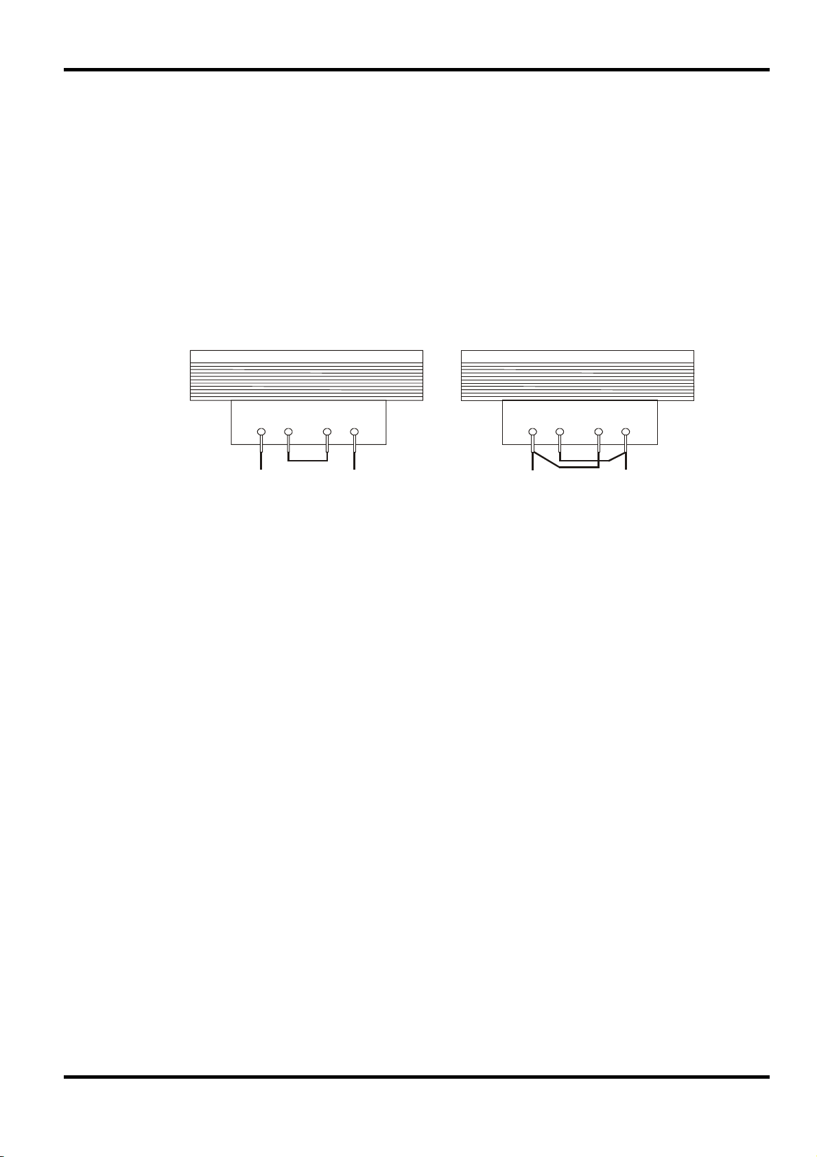
Netzbetriebsspannung
Prüfen Sie, dass die an der Geräterückplatte angezeigte Netzspannung Ihrem lokalen Netz
entspricht. Sollte es erforderlich sein, die Betriebsspannung zu ändern, gehen Sie wie folgt vor:
1. Stellen Sie sicher, dass das Gerät von der Netzstromversorgung getrennt ist.
2. Entfernen Sie die Plastikdrucknieten an allen Seitenkanten des Deckels. Nehmen Sie einen
kleinen Schraubendreher zur Hand, um zuerst den Nietkopf und danach die gesamte Niethülse
herauszuhebeln. Entfernen Sie die beiden Schrauben auf der Rückwand zur Befestigung des
Deckels - schieben Sie dann den Deckel nach hinten und nehmen Sie ihn ab.
3. Ändern Sie die Transformatoranschlüsse (beider Trafos im Falle des Doppelnetzgeräts) nach
folgender Zeichnung:
Installation
4. Die Wiedermontage erfolgt in umgekehrter Reihenfolge zum Ausbau. Um den
Sicherung
Die Wechselstromsicherung befindet sich im Sicherungsfach im unteren Teil des IEC
Netzsteckers (Einzelgeräte) oder in getrennten Sicherungshaltern für jeden Kanal
(Doppelgeräte).
Verwenden Sie in beiden Fällen eine Sicherung vom Typ 20 x 5 mm 250V HBC, träge, mit
folgenden Werten:
Sicherheitsvorschriften zu entsprechen, muss die auf der Rückwand angegebene
Betriebsspannung so geändert werden, dass die neue Einstellung der Betriebsspannung
deutlich zu erkennen ist.
230 V Bedienung 115 V Bedienung
BLAU BRAUN BLAU BRAUN
230V Bedienung : 1.6A (T)
Bedienung : 3.15A (T)
115V
Sicherstellen, dass nur Sicherungen des vorgeschriebenen Stromwerts und des vorgesehenen
Typs als Ersatz verwendet werden. Provisorische „Sicherungen“ und das Überbrücken von
Sicherungshaltern sind verboten!
Netzkabel
Schließen Sie das Gerät unter Verwendung des mitgelieferten Netzkabels an die
Wechselspannungsversorgung an. Falls ein Netzstecker für eine unterschiedliche Netzsteckdose
erforderlich ist, muss ein geeigneter und zugelassener Netzkabelsatz verwendet werden, der mit
dem geeigneten Wandstecker und einem IEC60320 C13-Stecker für das Geräteende versehen
ist. Zur Bestimmung der Mindest-Nennstromstärke des Kabelsatzes für die beabsichtigte
Wechselspannungsversorgung sind die Informationen zu Leistungswerten auf dem Gerät bzw. in
seiner Spezifikation hinzuzuziehen.
ACHTUNG! DIESES GERÄT MUSS GEERDET SEIN.
Jegliche Unterbrechung der Netzerde, ob im Innern oder außerhalb des Geräts, macht das Gerät
zur Gefahrenquelle! Eine absichtliche Unterbrechung ist verboten!
79
Page 84

Befestigung
Dieses Gerät kann auf einer Arbeitsplatte oder in einem Gestell befestigt werden. Ein RackMontagesatz für ein 19”-Rack ist vom Hersteller oder einem Fachhändler erhältlich.
Belüftung
Das Gerät wird mittels intelligenter Gebläse mit stufenweiser Drehzahlregelung gekühlt, um so
die Vertikalkonvektion zu unterstützen. Es muss sichergestellt werden, dass die Luftein- und auslässe auf der Unter- und Oberseite des Geräts nicht blockiert werden. Bei Geräten, die im
Rack montiert sind, muss genügend Raum um das Gerät gelassen werden und/oder eine
Zwangskühlung mittels eines zusätzlichen Ventilators eingesetzt werden.
Anschlüsse auf der Gerätevorderseite
Die Last sollte an die mit OUTPUT (Ausgang) gekennzeichneten positiven (roten) und negativen
(schwarzen) Klemmen angelegt werden. Beide Klemmen sind galvanisch getrennt und können
daher an Erde gelegt werden.
Die Fernfühleranschlüsse für die Last (falls gewünscht) erfolgen über die entsprechenden Plus(+) und Minus (-) SENSE Klemmen. Setzen Sie den Schalter LOCAL/REMOTE auf REMOTE,
wenn die Fernfühlerfunktion eingesetzt werden soll. Setzen Sie den Schalter auf LOCAL zurück,
wenn die Fernfühlerfunktion nicht verwendet wird.
Die mit
ABBILDING DER
FRONTPLATTE
markierte Klemme ist mit dem Gehäuse und dem Schutzleiter verbunden.
Anschlüsse
80
Page 85

Anschlüsse an der Geräterückseite
Nicht programmierbare Modelle besitzen keine Anschlüsse auf der Rückseite. Die rückseitigen
Anschlüsse der programmierbaren Geräte werden in der folgenden Abbildung gezeigt:
81
Page 86
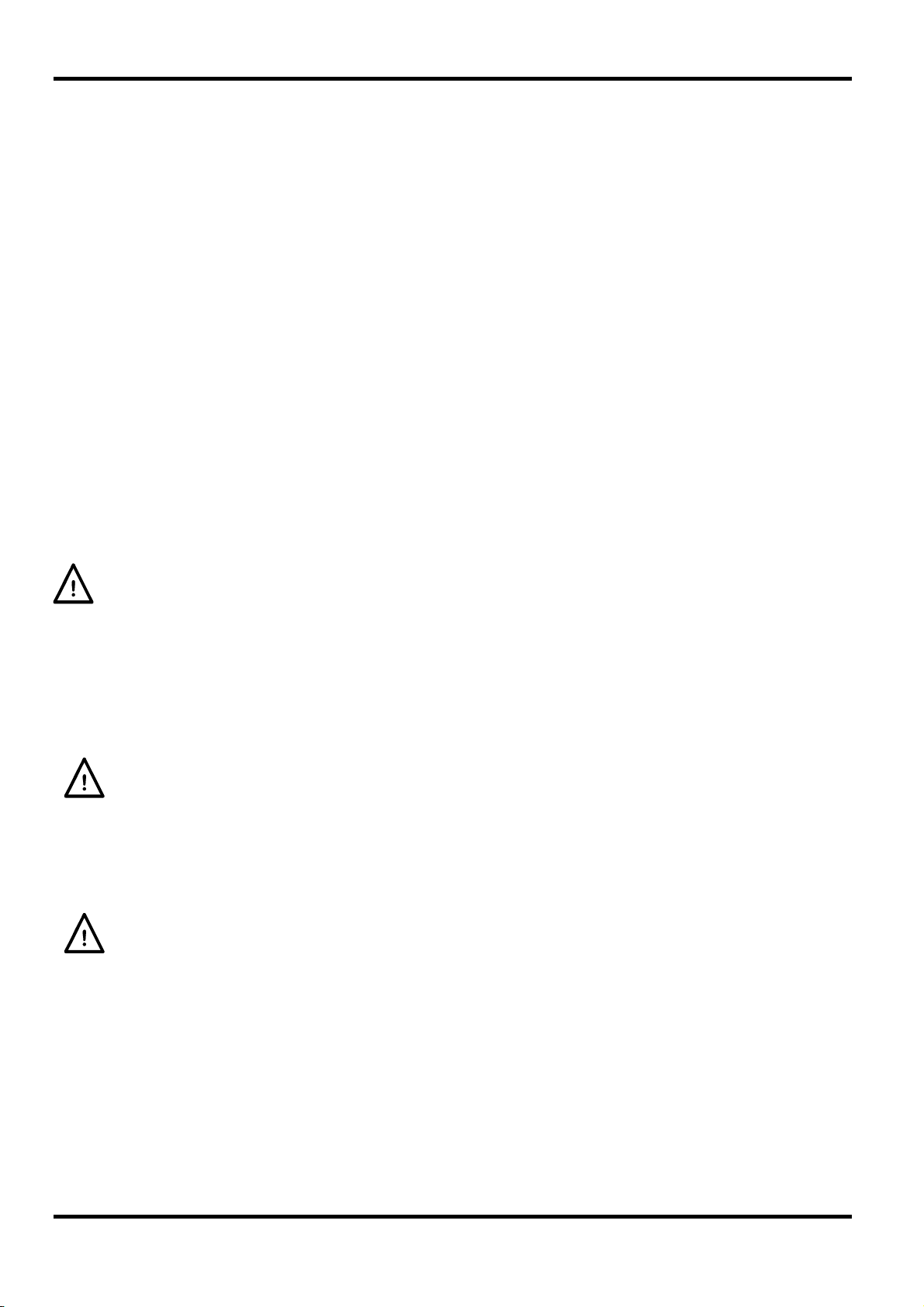
Hauptausgangs- und Fernfühlerklemmen (alle programmierbaren Modelle)
Die Ausgangs- und Fernfühleranschlüsse sind auch auf der Geräterückseite vorhanden
(Anschlussklemmen mit den Bezeichnungen „Output +, Output –, Sense +, Sense –“). Bei
Einzelnetzgeräten werden die Klemmen aufgrund mangelnder Beschriftungsfläche wie folgt
markiert +, −, S+ and S− (Gruppe OUT). Diese Anschlüsse sind mit ihren Äquivalenten auf der
Gerätefront parallel geschaltet.
Setzen Sie den Schalter LOCAL/REMOTE auf REMOTE, wenn die Fernfühlerfunktion eingesetzt
werden soll. Bei Verwendung der rückseitigen Ausgänge empfiehlt es sich die Fernfühlerfunktion
zu nutzen, um eine stabile Ausgangsspannung zu gewährleisten. Der Anschluss kann an die
Fernfühleranschlüsse auf der Vorder- oder auf der Rückseite erfolgen, jedoch nie an beide
gleichzeitig. Setzen Sie den Schalter auf LOCAL zurück, wenn die Fernfühlerfunktion nicht
verwendet wird.
Analogfernsteuerung (nur programmierbare Einzelgeräte)
Die Anschlüsse CV und CC ermöglichen die Analogsteuerung der Ausgangsspannung und der
Strombegrenzung, wenn die Schiebeschalter CV und CC auf Remote eingestellt sind. Die
Eingangsskalierung kann unabhängig durch interne Brücken auf 0-5 Volt (Werksvoreinstellung)
oder auf 0-10 Volt gestellt werden, um jeweils 0 bis 100% des Maximalwerts zu erreichen. Das
COM(MON)-Rücklaufsignal bezieht sich auf den positiven Ausgang des Netzgeräts. CV und CC
können einzeln oder zusammen verwendet werden.
Setzen Sie die Schalter CV und CC auf LOCAL zurück, wenn die Fernfühlerfunktion nicht
verwendet wird.
Legen Sie zwischen den Klemmen keine externe Spannung an, die den Maximalwert des
gewählten Bereichs (5V oder 10V) überschreitet.
Analogausgang (nur programmierbare Einzelgeräte)
Die Anschlüsse V
OUT
und I
sind Analogausgänge mit der jeweils eingestellten
OUT
Ausgangsspannung bzw. Strombegrenzung. Die Skalierung ist auf 0 bis 5 Volt entsprechend 0
bis 100% des Maximalausgangswerts festgelegt. V
vorhanden, ganz gleich, ob das Gerät im lokalen oder ferngesteuerten Modus betrieben wird. Das
COMMON-Rücklaufsignal bezieht sich auf den positiven Ausgang des Netzgeräts.
Legen Sie keine externe Spannung an diese Klemmen an.
Remote Ein/Aus (nur programmierbare Einzelgeräte)
Durch Schließen eines Schalters oder ein „Low“ Signal an den Anschlüssen REM OFF und COM
wird der Ausgang abgeschaltet. Das COM Rücklaufsignal bezieht sich auf den positiven Ausgang
des Netzgeräts.
Legen Sie keine externe Spannung an diese Klemmen an.
RS232 (nur XEL-P Modelle)
9−pol. D−Buchse mit den unten beschriebenen Pin-Belegungen. Kann mithilfe eines
vollverdrahteten Kabels (männlich-weiblich 1:1) ohne überkreuzende Verbindungen an einen
standardmäßigen PC-Port angeschlossen werden.
OUT
und I
sind an den Klemmen immer
OUT
82
Pin Bez.
1 RI
Beschreibung
Passive Bestimmung (+V durch 10 kΩ)
2 TXD Übertragungsdaten vom Gerät
3 RXD Empfangsdaten zum Gerät
Page 87

4 CTS
5 GND Signalmasse
6 RTS
7 DSR Keine interne Verbindung
8 DTR
9 CD Keine interne Verbindung
Signalmasse ist mit Gerätemasse verbunden.
USB (nur XEL-P Modelle)
Der USB-Port ist an die Geräteerde angeschlossen. Er entspricht USB 2.0 (Full Speed) und
akzeptiert ein standardmäßiges USB-Kabel. Falls der USB als aktuelle Schnittstelle ausgewählt
wurde, sollte die Plug-and-Play-Funktion von Windows automatisch erkennen, dass das Gerät
angeschlossen worden ist. Falls der korrekte Treiber nicht gefunden wird, befolgen Sie bitte die
Windows-Aufforderungen auf dem Bildschirm und installieren Sie die benötigten Dateien von der
mitgelieferten CD.
LAN (nur XEL-P Modelle)
Die LAN-Schnittstelle entspricht LXI ( Lan eXtensions for Instrumentation) Version 1.2; das Gerät
ist Class C konform. Eine Fernsteuerung über die LAN-Schnittstelle ist über das TCP/IP Sockets
Protokoll möglich. Das Gerät enthält auch einen einfachen Web-Server mit Informationen zum
Gerät, der eine Konfiguration ermöglicht. Da es durchaus möglich ist die LAN-Schnittstelle derart
falsch zu konfigurieren, dass ein Datenaustausch per LAN nicht mehr möglich ist, besitzt das
Gerät auf der Rückseite einen versenkten Schalter mit der Bezeichnung LAN RESET, sodass ein
Zurücksetzen auf die Werksvoreinstellung mithilfe des LCI (LAN Configuration Initialise)
Mechanismus möglich ist.
Weitere Details entnehmen Sie bitte dem Abschnitt „Ferngesteuerter Betrieb“. Weitere
Informationen zu den LXI Normen finden Sie auf www.lxistandard.org/home
Passive Bestimmung (+V durch 10 kΩ)
GPIB (Werksoption nur bei XEL-P Modellen)
Di GPIB Signalerde ist mit Geräteerde verbunden. Folgende Befehlssätze stehen zur Verfügung:
SH1 AH1 T6 TE0 L4 LE0 SR1 RL2 PP1 DC1 DT0 C0 E2
Die GPIB-Adresse wird von der Gerätevorderseite aus gesetzt.
83
Page 88

In diesem Bedienungshandbuch sind die Tasten, Steuerelemente und Buchsen auf der
Frontplatte in Großbuchstaben dargestellt, z. B. CURRENT, OUTPUT und LOCK. Meldungen auf
den 7-Segment LEDs werden in einer anderen Schriftart angegeben, z. B.:
trip
.
Einschalten und Einschaltzustand
Der Netzschalter befindet sich unten links auf der Gerätevorderseite. Nach dem Betätigen des
Netzschalters (
der Spannungs- und Stromanzeige.
Bei programmierbaren XEL-P Modellen verläuft die Anzeigesequenz beim Einschalten anders:
Die rechte Anzeige zeigt kurz die Firmware-Versionen von Gerät und Schnittstelle an (
erscheint auf der linken Anzeige), gefolgt von der Spannungs- und Stromanzeige. Wurde nach ein
paar Sekunden keine physische LAN-Verbindung erkannt, blinkt das Display 10 Sekunden lang
abwechselnd mit der normalen Strom-/Spannungsanzeige und der Meldung
Anzeige einer fehlenden LAN-Verbindung ist eine wesentliche LXI Anforderung, kann aber mit
dem Befehl 'NOLANOK 1' über eine beliebige Schnittstelle deaktiviert werden (weitere
Einzelheiten hierzu finden Sie im Abschnitt „LAN Fehler“ im Kapitel „Bedienung der
Fernschnittstelle“). Diese Änderung der Starteinstellungen nach dem Einschalten bleibt erhalten,
bis der Befehl 'NOLANOK 0' gegeben wird oder die Werksvoreinstellung für die LANEinstellungen durch den LAN RESET Schalter auf der Rückseite wiederhergestellt wird (siehe
hierzu den Abschnitt zu LAN im Kapitel „Bedienung der Fernschnittstelle“.
Beachten Sie bitte, dass die Anzeigeinformationen den eigentlichen Betrieb des Netzteils nicht
berühren.
Beim Einschalten ist das Gerät vom Werk aus so eingerichtet, dass der Ausgang abgeschaltet ist.
Die Werte für Ausgangsspannung und Strom hängen von den jeweiligen Steuereinstellungen ab
und werden auf dem Display angezeigt. Alle anderen Einstellungen entsprechen dem Zustand
vor dem letzten Abschalten des Geräts.
Wenn Sie diesen Vorgang wiederholen wird die Einstellung wieder rückgängig gemacht.
Beachten Sie, dass der Einschaltzustand des Doppelnetzgeräts für jeden Ausgang einzeln
eingerichtet werden muss.
l ) wird auf der rechten Anzeige kurz die Firmware-Version angezeigt, gefolgt von
Der Gleichspannungsausgang kann so eingerichtet werden, dass er beim
Einschalten des Geräts entweder immer ausgeschaltet ist oder den Zustand
vor dem letzten Ausschalten des Geräts annimmt. Diese Einstellung kann wie
folgt geändert werden: Bei gedrückter VIEW Taste, die Taste
drücken und halten – auf dem Display erscheint nun 1 Sekunde lang die
aktuelle Einstellung (
Anschließend zeigt das Display 2 Sekunden lang blinkend die neue
Einstellung an (
Einstellung kontinuierlich angezeigt und die Änderung durchgeführt. Geben
Sie nun die Tasten OUTPUT und VIEW frei.
Manueller Betrieb
turn oFF, OtP
IF
LAn Err. Die
OUTPUT
OP OFF falls die Werksvoreinstellung gewählt ist).
LASt Set in diesem Fall). Nach 2 Sekunden wird die neue
Ausgangsregelung
Einrichten des Ausgangs
Bei eingeschalteter Stromversorgung und ausgeschaltetem OUTPUT (Ausgang) können Sie
die Spannungs- und Strombegrenzung mit den Reglern VOLTAGE und CURRENT präzise regeln.
Die linke Anzeige zeigt die eingestellte Spannung und die rechte Anzeige den maximalen Strom
an - die SETTINGS Anzeige leuchtet auf.
84
Page 89
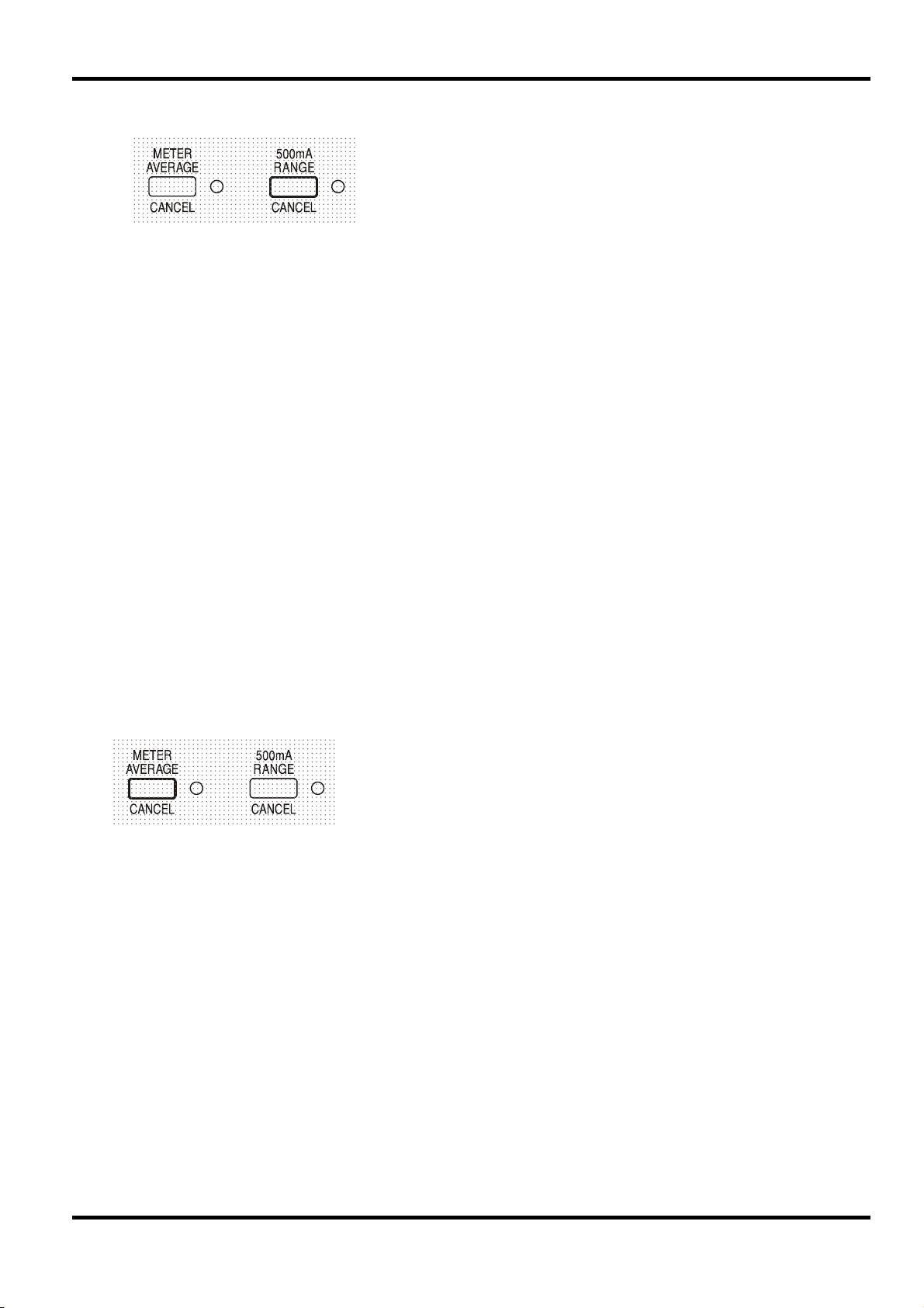
Bei eingeschaltetem Ausgang leuchtet die OUTPUT Anzeige auf – das linke Messinstrument
zeigt jetzt die tatsächliche Spannung und das rechte Messinstrument den aktuellen Laststrom.
Die Anzeige neben der Taste leuchtet auf, wenn der 500 mA Bereich gewählt ist. Um den
Strombegrenzungsbereich ändern zu können, muss der Ausgang abgeschaltet werden - sollte
der Ausgang noch eingeschaltet sein, erscheint kurz die Meldung
OUTPUT Anzeige blinkt und der Bereich bleibt unverändert.
Konstantspannung
Die Ausgangsspannung wird mit den VOLTAGE Grob- und Feinreglern geregelt; mit dem Regler
CURRENT wird der Maximalstrom eingestellt.
Konstantstrom
Wenn der Lastwiderstand so niedrig ist, dass bei der gewählten Ausgangsspannung ein höherer
Strom fließen würde, als durch die Strombegrenzung vorgegeben, so schaltet das Netzgerät
automatisch auf Konstantstrombetrieb. Der Ausgangsstrom wird mit dem CURRENT Regler
eingestellt, während die VOLTAGE Regler die maximal erzeugte Spannung bestimmen.
Die Konstantstromanzeige (CC) leuchtet auf, um den Betrieb mit Konstantstrom anzuzeigen.
Der obere Grenzwert für den CURRENT Regler kann durch
abwechselndes Drücken der RANGE Taste zwischen dem
Maximalwert für dieses Gerät und 500 mA umgeschaltet werden, um
so eine Feineinstellung der Strombegrenzung und der Messauflösung
(0,1 mA bis zu 500 mA) zu erreichen.
turn oFF im Display, die
Momentanstrom
Mit Hilfe der Strombegrenzungsfunktion kann der Dauerausgangsstrom bis auf 1 mA herab
begrenzt werden (0,1 mA im 500 mA Bereich). Wie bei allen Präzisionsnetzgeräten wird jedoch
auch hier ein Kondensator am Ausgang parallel geschaltet, um eine stabile Ausgangsspannung
und ein gutes dynamisches Verhalten zu gewährleisten. Dieser Kondensator lädt sich bis zur
Höhe der Ausgangsspannung auf und erzeugt beim Anschließen einer Ausgangslast durch seine
Entladung einen Stromimpuls, auf den die Strombegrenzung keinen Einfluss hat.
Mittelwerte der Stromstärkemessung
Um die Messschwankungen bei veränderlichen Lasten zu
reduzieren, kann durch Drücken auf die Taste METER AVERAGE
eine Zeitkonstante von 2 Sekunden gewählt werden – ist diese
Funktion aktiviert, so leuchtet eine Anzeige neben der Taste auf.
Drücken Sie die Taste erneut, um diese Mittelung zu annullieren und
zur Standardzeitkonstante von 20 ms zurückzukehren.
Wirkungsgrad
Das Netzgerät reduziert Leistungsverluste durch elektronische Vorregelung, um eine niedrige
Gesamtspannung an den Leistungsreglern zu erhalten. Darüber hinaus wird die Trafoanzapfung
über ein Relais intelligent geregelt, um den Betrieb bei extremer Netzeingangsspannung bzw. DC
Ausgangsleistung zu optimieren. Am Schwellenwert wird eine Hysteresefunktion eingesetzt, um
unnötiges Schalten in Nähe dieses Werts zu verhindern. Von einem kaum hörbaren „Klick”
abgesehen, ist das Schalten des Relais unmerklich – am Ausgang ist keine Störung bemerkbar.
Programmierbare Modelle verwenden Spezialtrafos, die keine relaisgesteuerte Anzapfung
erfordern.
Anschluss der Last
Die Last sollte an die mit OUTPUT gekennzeichneten positiven (rot) und negativen (schwarz)
Klemmen angelegt werden. Beide Klemmen sind galvanisch getrennt und können daher an Erde
gelegt werden.
85
Page 90

Fernfühlerfunktion
Obwohl das Gerät eine sehr geringe Ausgangsimpedanz besitzt, erhöht sich diese zwangsweise
durch den Widerstand der angeschlossenen Kabel. Bei hohen Strömen ergibt sich hieraus ein
deutlicher Unterschied zwischen der angezeigten Quellspannung und der tatsächlichen
Lastspannung (zwei Anschlusskabel mit 20 mΩ erzeugen z. B. bei einem Strom von 5 A einen
Spannungsabfall von 0,2 V).
Um Instabilität und dynamisches Fehlverhalten zu vermeiden muss darauf geachtet werden, dass
eine gute Verbindung zwischen jedem Ausgangs- und Fernfühlerkabel besteht. Dies wird erreicht,
indem man entweder die Kabel miteinander verdrillt oder ein abgeschirmtes Koaxialkabel
verwendet (die Fernfühlerleitung bildet hierbei den Innenleiter). Auch ein zum Lastanschluss
parallel geschalteter Elektrolytkondensator kann hilfreich sein.
Der Spannungsabfall des jeweiligen Ausgangskabels darf 0,5 Volt nicht überschreiten.
Setzen Sie den LOCAL/REMOTE Schalter auf LOCAL zurück, wenn die Fernfühlerfunktion nicht
verwendet wird.
Dieses Problem lässt sich zwar durch Verwendung kurzer
Anschlusskabel mit großem Querschnitt einschränken, es ist
aber besser, diesen Effekt mit Hilfe der Fernfühlerfunktion
ganz zu umgehen. Dazu müssen die Fernfühlerklemmen
(Sense) an der Last anstelle der Spannungsquelle
angeschlossen werden. Schließen Sie die Kabel an die
Federklemmen des SENSE-Anschlusses und direkt an der
Last an. Setzen Sie den Schalter LOCAL/REMOTE auf
REMOTE.
Ausgangsklemmen und Fernfühlerfunktion bei programmierbaren Modellen
Alle programmierbaren Modelle besitzen zusätzliche Ausgangs- und Sense-Klemmen auf der
Rückseite (nützlich beim Rack-Einbau). Bei Verwendung der rückseitigen Ausgänge empfiehlt es
sich die Fernfühlerfunktion zu nutzen, um eine stabile Ausgangsspannung zu gewährleisten. Der
Anschluss kann an die Fernfühleranschlüsse auf der Vorder- oder auf der Rückseite erfolgen,
jedoch nie an beide gleichzeitig. Schließen Sie die Sense-Klemmen unter Beachtung obiger
Empfehlungen an die Last an und setzen Sie den Schalter LOCAL/REMOTE auf REMOTE.
Wenn die rückseitigen Ausgangsklemmen ohne Einsatz der Fernfühlerfunktion verwendet werden
ist unbedingt darauf zu achten, dass der Schiebeschalter auf der Vorderseite auf LOCAL gesetzt
ist. Die Regelung verschlechtert sich aufgrund des geringen Spannungsabfalls in der
Verdrahtung zu den rückseitigen Klemmen etwas, wenn die Fernfühlerfunktion ausgeschaltet ist.
Serielle oder Parallelschaltung mit anderen Spannungsquellen
Der Ausgang des Netzgeräts ist galvanisch getrennt und kann mit anderen Netzgeräten in Reihe
geschaltet werden, um hohe Gleichstromspannungen bis zu 300 V DC zu erzeugen.
86
Die maximal zulässige Spannung zwischen einer Anschlussklemme und Erde (
) beträgt 300 V DC
ACHTUNG! Spannungen dieser Größenordnung sind äußerst gefährlich. Daher müssen die
Ausgangsklemmen bei Verwendung derartiger Spannung unbedingt vor Berührung geschützt
werden. Auf keinen Fall dürfen die Ausgangsklemmen in einem solchen Fall berührt werden.
Sämtliche Anschlüsse an den Klemmen dürfen erst dann erfolgen, wenn alle betreffenden
Netzgeräte ausgeschaltet sind.
Zu beachten ist, dass das Gerät nur als Stromquelle dient und keine Ströme ableiten kann, d. h.
es können keine gegenphasigen Geräte angeschlossen werden.
Das Gerät kann auch mit anderen Netzteilen parallel geschaltet werden, um eine höhere
Stromabgabe zu erzielen. Werden mehrere Geräte parallel geschaltet, entspricht die
Ausgangsspannung dem Gerät mit der höchsten Ausgangsspannung. Dies gilt nur, solange der
Strombegrenzungswert des betreffenden Geräts nicht erreicht wird. Ist dies der Fall, fällt die
Ausgangsspannung auf die nächsthöchste Einstellung ab, usw. Bei Konstantstrombetrieb können
mehrere Geräte parallel geschaltet werden, um einen Strom mit der Summe der jeweiligen
Stromgrenzwerte bereitzustellen.
Page 91
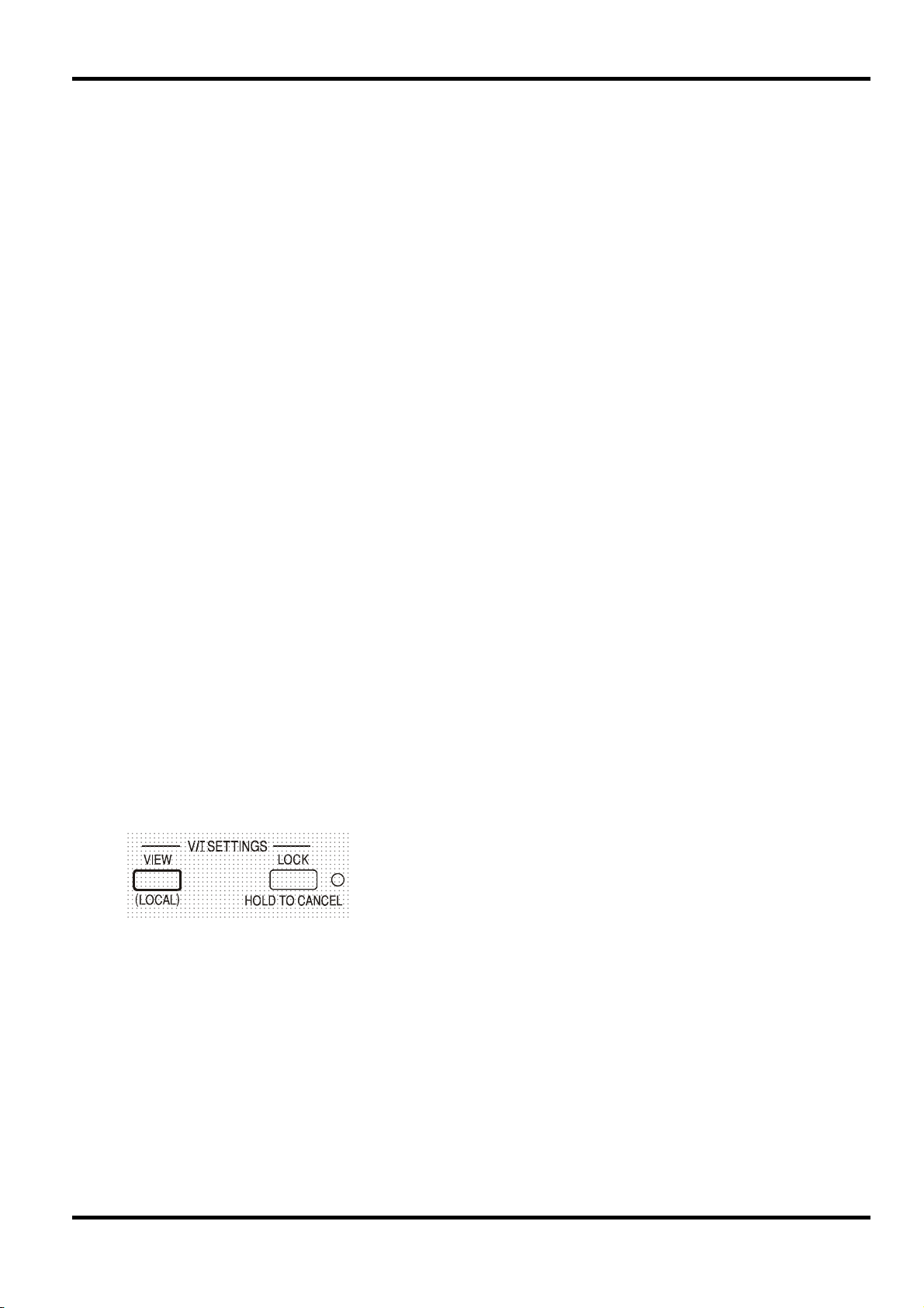
Schutzvorrichtungen
Der Ausgang ist eigensicher gegen Kurzschlüsse und zusätzlich durch eine Diode gegen
Rückspannung geschützt. Diese Rückspannung darf 3 Ampere nicht überschreiten (Stromspitzen
dürfen erheblich höher liegen). Falls die anliegende Rückspannung mehr Strom abgibt, als durch
die Strombegrenzung eingestellt ist, schaltet der Ausgang (sofern aktiviert) auf Strombegrenzung
(CC Anzeige blinkt) und zeigt im Display die Rückspannung an der Schutzdiode an. Ist der
Ausgang deaktiviert, so blinkt lediglich die CC Anzeige.
Wie alle seriengeregelten, unsymmetrischen Netzgeräte kann auch dieses Gerät nicht
stromziehend arbeiten. Wird eine Spannung von einer externen Quelle angelegt, die höher liegt
als die eingestellte Ausgangsspannung, so schaltet sich die interne Regelung ab, sodass keine
Strom mehr fließen kann. Wenn der Ausgang eingeschaltet ist zeigt das Messinstrument die
angelegte Spannung an. Eine Beschädigung findet nicht statt, vorausgesetzt die angelegte
Spannung überschreitet die maximale Ausgangsspannung des Netzgeräts um nicht mehr als 20
Volt.
Bei ausgeschaltetem OUTPUT und weiterhin angeschlossener Last wird die Ausgangsspannung
einfach auf Null gesetzt. Legen Sie keine externen Spannungen an den Klemmen des Netzgeräts
an, die mehr als 20 V über der Nennausgangsspannung liegen, da sonst selbst bei
ausgeschaltetem Ausgang Schäden möglich sind.
Übertemperaturschutz
Ein integrierter Sensor erkennt Übertemperaturen aufgrund von blockierter Luftströmung,
Lüfterausfall oder einem Schaltungsfehler. Bei Übertemperatur wird der Ausgang abgeschaltet –
die OUTPUT Anzeige blinkt und auf dem Display erscheint die Meldung
die Ursache für die Übertemperatur behoben wurde und das Gerät abgekühlt ist, geht die
Ausgangsanzeige aus - die Meldung
Taste OUTPUT einmal drücken zeigt das Display die voreingestellten Werte für Strom und
Spannung an (die Anzeige SETTINGS leuchtet auf), der Ausgang bleibt jedoch abgeschaltet –
erst beim zweiten Drücken der Taste wird der Ausgang normal eingeschaltet.
OtP triP . Nachdem
OtP triP wird jedoch weiterhin angezeigt. Wenn Sie die
Wird die Taste OUTPUT gedrückt, während das Gerät Übertemperatur aufweist (Anzeige
OUTPUT blinkt), wird die Meldung
Strom und Spannung ersetzt (die Anzeige SETTINGS leuchtet auf), der Ausgang bleibt jedoch
abgeschaltet – bei jedem folgenden Drücken der Taste OUTPUT wird die Meldung
kurz angezeigt, der Ausgang bleibt jedoch abgeschaltet, bis das Übertemperaturproblem beseitigt
ist.
Einstellungen für das Display
Einstellungen für die Verriegelung
Durch Drücken der Taste LOCK wird die Strom- und Spannungsbegrenzung digital verriegelt. Die
Einstellungen werden mit hoher Genauigkeit (besser als 1 Stelle) bei absoluter Stabilität
gespeichert. Anschließende Veränderungen der Regler VOLTAGE und CURRENT bleiben
wirkungslos.
Da eine Annullierung von LOCK zu einer Änderung der Ausgangseinstellungen führen würde
(falls die Einstellung für VOLTAGE und CURRENT in der Zwischenzeit verändert wurde),
erscheint eine Warnmeldung bevor die Funktion LOCK annuliert wird.
Hierzu die Taste gedrückt halten, um LOCK zu annullieren.
Bei abgeschaltetem Ausgang (sicherer Zustand) blinken die „unverriegelten“ Einstellungen
zweimal kurz im Display auf, bevor die Änderung durchgeführt wird. Die LOCK Leuchte geht
dann aus.
OtP triP durch die Anzeige der voreingestellten Werte für
OtP triP
Die eingestellten Spannungs- und Strombegrenzungswerte
werden immer angezeigt, wenn der Ausgang abgeschaltet ist,
können aber auch bei eingeschaltetem Ausgang eingesehen
werden, wenn Sie die Taste VIEW drücken – die SETTINGS
Anzeige leuchtet auf, während die VIEW Taste gedrückt ist.
87
Page 92

g
Die LOCK Anzeige geht aus, sobald die Änderung erfolgt ist. Beim Loslassen der Taste LOCK,
während das Display blinkt, wird die Deaktivierung der LOCK Funktion abgebrochen.
Die Änderung des Strombegrenzungsbereichs (siehe „”Einrichten des Ausgangs“) bzw. des
Spannungsbegrenzungsbereichs (siehe „Spannungsbereich“) bei aktivierter LOCK Funktion ist
nicht gestattet – bei einem Versuch erscheint kurz die Meldung
LOCK Anzeige blinkt auf. Wird dieser Versuch bei eingeschaltetem Ausgang unternommen,
erscheint zunächst die Meldung
Ausgangsanzeige), gefolgt von der Meldung
Der LOCK Status beim Einschalten entspricht dem Zustand beim letzten Ausschalten.
Verwendung des Spannungsbereichs
Die Funktion VOLTAGE SPAN (V-Span) ermöglicht die Neudefinierung der Grenzwerte für die
VOLTAGE Regler, sodass der Anwender die Regler nur in einem speziellen, begrenzten
Spannungsbereich einstellen kann. Dies hat nicht nur den Vorteil, dass das versehentliche
Anlegen einer falschen Spannung an die Last verhindert wird, sondern auch, dass sich der nun
begrenzte Spannungsbereich unter voller Nutzung des Einstellbereichs von 300º mit dem
Analogregler feinfühliger einstellen lässt.
Wenn der Ausgang noch eingeschaltet ist blinkt die Meldung OP
on
(Ausgang Ein) zweimal im Display auf. Anschließend werden
die neuen „unverriegelten“ Einstellungen 2 bis 3 Sekunden lang
angezeigt (zuerst langsam, dann schneller), bevor die Änderung
schließlich durch
eführt wird.
Unloc im Display und die
turn oFF im Display (zusammen mit blinkender
Unloc (mit blinkender LOCK Anzeige).
V-Span wird mit der Taste ENABLE aktiviert. Die
ENABLE Lampe leuchtet auf, wenn V-Span gewählt
ist. Der voreingestellte Wert ist V
5V, V
max
=10V
= 3V, V
min
max
= 5V
Da sich bei der Aktivierung von V-Span immer die Ausgangsspannung ändert, kann diese
Funktion nur bei ausgeschaltetem Ausgang aktiviert bzw. deaktiviert werden - beim Versuch
V-Span bei eingeschaltetem Ausgang zu (de)aktivieren, erscheint kurz die Meldung
turn oFF
um den Anwender darauf aufmerksam zu machen, dass der Ausgang abgeschaltet werden muss.
Um neue Werte für V
min
oder V
einrichten zu können, muss die V-Span Funktion deaktiviert
max
sein.
Die untere Spannungsgrenze wird mit den Reglern MAIN und FINE VOLTAGE exakt auf den
gewünschten Wert gesetzt – dann die Taste V
gedrückt halten, bis das (V) Display auf der
min
linken Seite aufhört zu blinken und das Display auf der rechten Seite (mA) Set zeigt. Die
Einstellung kann durch kurzes Drücken (< 1 Sekunde) der Taste V
obere Spannungsgrenze kann mittels des VOLTAGE Regler und der Taste V
eingesehen werden. Die
min
auf gleiche
max
Weise eingestellt und kontrolliert werden.
Die Grenzwerte können in beliebiger Reihenfolge und innerhalb des Ausgangsbereichs des
Geräts auf einen beliebigen Wert gesetzt werden – allerdings kann V-Span mit der Taste ENABLE
nur dann aktiviert werden, wenn V
die Meldung
Set Err und die Funktion V-Span wird nicht aktiviert.
max
≥ (V
+ 0,1 V). Ist dies nicht gegeben, so erscheint kurz
min
88
Bei aktivierter V-Span Funktion umfasst der Regelbereich für den MAIN VOLTAGE Regler genau
bis V
V
min
markiert). Mit dem FINE Regler kann eine zusätzliche Feinabstimmung von ± 1% (des
•
wenn sich der FINE Regler in der Mittenstellung befindet (auf dem Gerät mit einem
max
Spannungsbereichs) vorgenommen werden.
Der V-Span Status beim Einschalten entspricht dem Zustand beim letzten Ausschalten.
Page 93

Betriebsarten des Doppelnetzgeräts (Quad-Mode Dual)
Im folgenden werden die vier Betriebsarten dieses
Doppelnetzgeräts beschrieben. Die Einstellung der Betriebsart
erfolgt mit dem MODE Drehschalter. Damit an den
angeschlossenen Schaltungen keine unverträglichen
Spannungen anliegen, werden beim Wechsel der Betriebsart
immer beide Ausgänge abgeschaltet.
Ungewollte Spannungsspitzen können jedoch nie ganz ausgeschlossen werden, sodass
Wechsel der Betriebsart immer beide Ausgänge abgeschaltet werden müssen
Unabhängig
Drehen Sie den MODE Schalter auf INDEPENDENT (Unabhängig). Beide Ausgänge arbeiten
nun völlig unabhängig voneinander und sind elektrisch voneinander isoliert. Sie können wie oben
im Abschnitt „Ausgangsregelung“ beschrieben eingestellt werden.
Ein Umschalten vom unabhängigen Betrieb auf Tracking-Betrieb ist nicht möglich, wenn die
LOCK-Funktion des Slave-Ausgangs aktiviert ist. In diesem Fall erscheint die Meldung
im Slave-Display. Die Funktion LOCK muss zuerst deaktiviert werden (im unabhängingen
Betrieb) bevor ein Umschalten auf Tracking-Betrieb möglich ist.
Siehe hierzu auch den Abschnitt zur „Beibehaltung der Slave-Einstellungen“.
Isolierte Synchronregelung
Drehen Sie den MODE Schalter auf ISOLATED TRACKING (Isolierte Synchronregelung) . Beide
Ausgänge bleiben elektrisch voneinander isoliert, allerdings wird nun durch die Spannungsregler
des Master-Ausgangs eine identische Spannung am Slave-Ausgang erzeugt. Die Stromregler des
Slave-Ausgangs lassen sich weiter unabhängig bedienen (einschl. des 500mA Bereichs und der
Mittelungsfunktionen).
Durch die elektrische Entkopplung können die beiden Ausgänge beispielsweise TrackingSpannungen mit entgegengesetzter Polarität oder identische Spannungen für unterschiedliche
Bezugspotentiale liefern (z. B. digitale Masse und analoge Masse).
vor dem
.
Un loc
Die Funktionen LOCK und VOLTAGE SPAN des Master-Ausgangs arbeiten exakt wie oben
beschrieben und regeln aufgrund der aktivierten Synchronregelung auch die SlaveAusgangsspannung. Beachten Sie, dass bei Verwendung der Master LOCK Funktion nur die
Ausgangsspannung des Slave „verriegelt“ wird – die Stromregler des Slave (einschl. des 500mA
Bereichs und der Mittelungsfunktionen) lassen sich weiter unabhängig bedienen.
Die LOCK Taste des Slave-Ausgangs wird ignoriert. Beim Drücken dieser Taste erscheint
lediglich kurz die Meldung
Sie können auch bei aktivierter LOCK Funktion am Master vom Tracking-Betrieb auf
unabhängigen Betrieb zurückschalten. In diesem Fall bleiben die Einstellungen des rechten
Master-Ausgangs „verriegelt“, die Einstellungen des linken Ausgangs können dagegen frei
gewählt werden.
Die Spannungsbereichstasten des Slave erhalten im Tracking-Betrieb eine andere Funktion –
siehe hierzu den nächsten Abschnitt.
89
In trac auf der Slave-Anzeige.
Page 94

)
Isolierte prozentuale Synchronregelung
Drehen Sie den MODE Schalter auf ISOLATED TRACKING.
Das Gerät arbeitet wie im vorherigen Abschnitt beschrieben, jedoch kann die Slave-Spannung mit
dem Slave-Spannungsregler auf einen Prozentsatz (0% bis 101%) der Master-Spannung
eingestellt werden. Dieses Verhältnis wird bei einer Veränderung der Master-Spannung
aufrechterhalten.
Durch erneutes Drücken auf ENABLE wird der Slave-Ausgang wieder in den normalen TrackingBetrieb zurückversetzt (ENABLE Leuchte aus).
Die Aktivierung/Deaktivierung der prozentualen Synchronregelung ist nur bei ausgeschaltetem
Ausgang möglich. Ist der Ausgang eingeschaltet, so erscheint beim Drücken der Taste ENABLE
kurz die Meldung turn oFF und es erfolgt keine Änderung.
Bei aktivierter prozentualer Synchronregelung erscheint kurz die Meldung Pcnt on auf dem
Slave-Display, bevor wieder die aktuell eingestellte Ausgangsspannung angezeigt wird.
Aktivieren Sie diese Betriebsart, indem Sie die
Taste ENABLE im Bereich VOLTAGE SPAN
des Slave-Ausgangs drücken (ENABLE
Leuchte an
.
Sie können den Prozentwert jederzeit darstellen, indem Sie die Taste V
Ausgang drücken. Bei Drücken und Halten dieser Tasten erscheint die Prozenteinstellung in der
Form 90.0 Pcnt und der Verhältniswert kann mit den Slave-Spannungsreglern eingestellt
werden. Der Prozentwert kann vor Aktivierung der prozentualen Synchronregelung eingestellt
werden (ENABLE Leuchte aus).
Die Funktionen LOCK und VOLTAGE SPAN des Master-Ausgangs arbeiten exakt wie oben
beschrieben. Allerdings kann bei aktivierter prozentualer Synchronregelung der Verhältniswert für
die Slave-Spannung mit den Slave-Spannungsreglern weiterhin eingestellt werden, obwohl die
Master-Spannung verriegelt ist. Der Status des Ratio Tracking Mode beim Einschalten entspricht
dem Zustand beim letzten Ausschalten.
Siehe hierzu auch den Abschnitt zur „Beibehaltung der Slave-Einstellungen“.
Parallelbetrieb
Drehen Sie den Schalter MODE auf PARALLEL (Parallelbetrieb). Das Gerät arbeitet nun
vollständig parallel, sodass die gesamte Leistung von bis zu 6 Ampere am Master-Ausgang zur
Verfügung steht. Der Slave-Ausgang ist deaktiviert und das entsprechende Display
ausgeschaltet.
Im Parallel-Betrieb verdoppelt sich der Strombegrenzungswert bei gleicher Einstellung des
Strombegrenzungsreglers. Dies gilt auch für den 500mA Bereich, der nun maximal 1000mA
abgeben kann. Zur Warnung blinkt die Stromanzeige beim Anwählen der Parallelfunktion zweimal
auf, bevor dann der neue Begrenzungswert angezeigt wird. Die Stromanzeige blinkt auch beim
Umschalten von Parallel- auf Tracking-Betrieb zweimal auf, um darauf hinzuweisen, dass sich die
Master-Strombegrenzung nun halbiert hat.
min
oder V
am Slave-
max
90
Die Funktionen LOCK und VOLTAGE SPAN des Master-Ausgangs arbeiten exakt wie oben
beschrieben. Sie können auch bei aktivierter LOCK Funktion am Master vom Parallel-Betrieb
zurück auf Tracking-Betrieb (und umgekehrt) schalten. Die Spannungs- und Stromregler des
Master-Ausgangs bleiben verriegelt (siehe oben). Jedoch verdoppelt (bei Umschalten von
Tracking auf Parallel) bzw. halbiert (bei Umschalten von Parallel auf Tracking) sich der aktuell
eingestellte Strombegrenzungswert des Master-Ausgang, obwohl LOCK aktiviert ist. Dieser
Umstand wird durch das zweimalige Blinken des Displays angezeigt.
Page 95

Beibehaltung der Slave-Einstellungen
Wenn V-Span für den Slave-Ausgang im unabhängigen Betrieb (INDEPENDENT) aktiviert ist, so
wird diese Einstellung bei Umschalten auf TRACKING Betrieb außer Kraft gesetzt, jedoch bei
erneuerter Wahl von INDEPENDENT wieder aktiviert.
Wenn „Ratio (%) Tracking“ für den Slave-Ausgang im TRACKING Betrieb aktiviert ist, so wird
diese Einstellung beim Umschalten auf INDEPENDENT oder PARALLEL außer Kraft gesetzt,
jedoch bei erneuter Wahl von TRACKING wieder aktiviert.
Gleichzeitiges Ein- und Auschalten beider Ausgänge
Die Tasten „Both On / Both Off“ (Beide Ein / Beide Aus) stehen zusätzlich zu
den einzelnen OUTPUT Schaltern zur Verfügung und ermöglichen das
gleichzeitige Ein- und Ausschalten beider Ausgänge über einen
Schalterdruck. Diese Tasten sind in allen vier Betriebsarten betriebsfähig.
91
Page 96
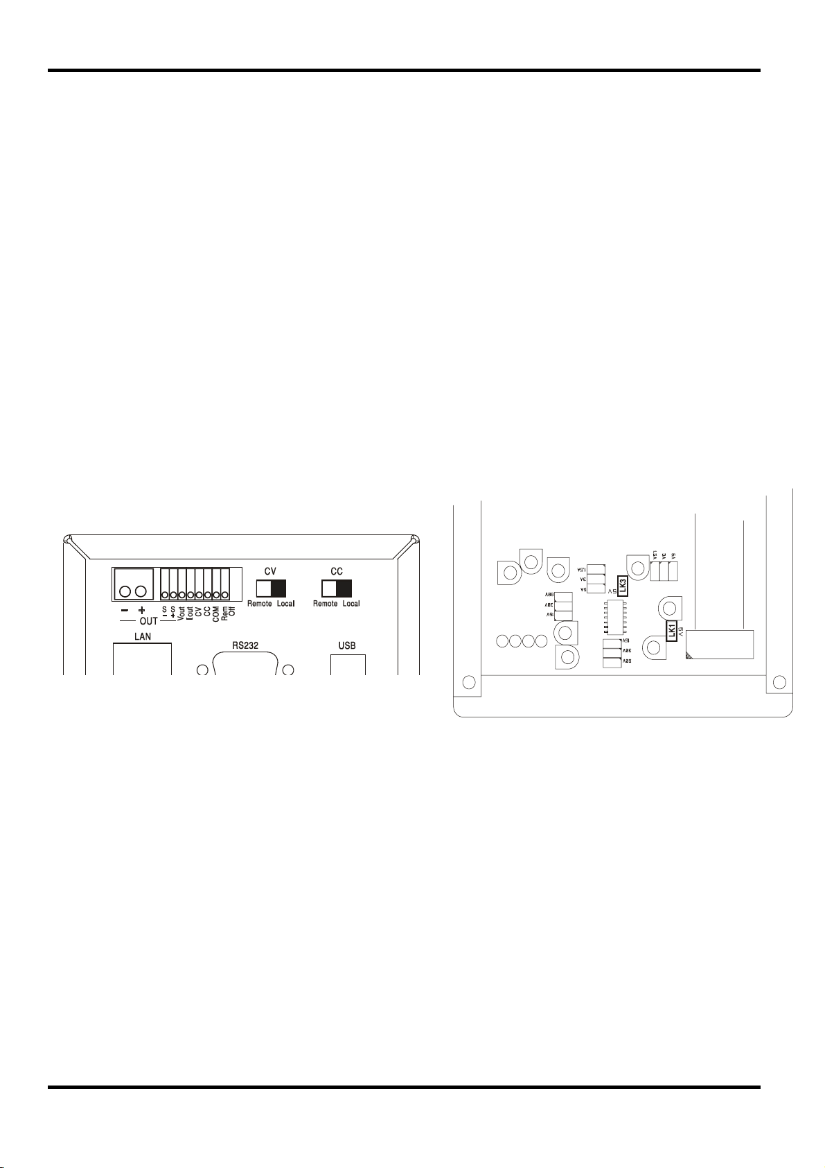
Analogfernsteuerung (nur programmierbare
Die Analogfernsteuerung von Ausgangsspannung und Strom ist über externe Steuerspannungen
möglich, die an den Eingängen CV und COM bzw. CC und COM auf der Geräterückseite
angelegt werden.
Die Steuerspannungen V
Geräts über die CV bzw. CC Eingänge des Slave-Geräts verwendet werden.
Analoge Spannungssteuerung
Die Fernsteuerung der Spannung erfolgt, indem der rückseitige Schalter CV auf REMOTE
gesetzt, und eine Programmierspannung zwischen den Eingängen CV und COM angelegt wird.
Wenn der CV Schalter auf REMOTE steht, sind die Spannungsregler auf der Vorderseite
deaktiviert. Setzen Sie den Schalter auf LOCAL zurück, um die Spannung über die Regler auf
der Vorderseite kontrollieren zu können.
Die Standardskalierung der Eingangsspannung liegt zwischen 0V und 5V, um 0 bis 100% der
Nennausgangsspannung zu erreichen. Durch Entfernen einer internen Brücke kann die
Eingangsspannung auch auf den Bereich 0V bis 10V skaliert werden. Trennen Sie das Gerät von
der Wechselstromversorgung und nehmen Sie den Deckel ab (siehe Anweisungen im Abschnitt
„Installation“. Entfernen Sie die Brücke LK1, die in der Draufsicht der folgenden Abbildung zu
sehen ist.
Die Spannungsfernsteuerung kann bei lokaler oder ferngesteuerter Strombegrenzung verwendet
werden.
und I
out
Einzelgeräte)
eines Master-Geräts können auch zur Steuerung eines Slave-
out
Analoge Stromsteuerung
Die Fernsteuerung des Konstantstroms erfolgt, indem der rückseitige Schalter CC auf REMOTE
gesetzt, und eine Programmierspannung zwischen den Eingängen CC und COM angelegt wird.
Eine Fernsteuerung der Stromstärke ist nur im Hochstrombereich möglich, nicht im 500mA
Bereich.
Wenn der CC Schalter auf REMOTE steht, ist der Stromstärkeregler auf der Vorderseite
deaktiviert. Setzen Sie den Schalter auf LOCAL zurück, um wieder den Regler auf der
Vorderseite benutzen zu können.
Die Standardskalierung der Eingangsspannung liegt zwischen 0V und 5V, um 0 bis 100% des
Nennausgangsstroms zu erreichen (nur im Hochstrombereich). Durch Entfernen einer internen
Brücke kann die Eingangsspannung auch auf den Bereich 0V bis 10V skaliert werden. Trennen
Sie das Gerät von der Wechselstromversorgung und nehmen Sie den Deckel ab (siehe
Anweisungen im Abschnitt „Installation“. Entfernen Sie die Brücke LK3, die in der Draufsicht der
obigen Abbildung zu sehen ist.
Die Stromfernsteuerung kann bei lokaler oder ferngesteuerter Spannungssteuerung verwendet
werden.
92
Page 97
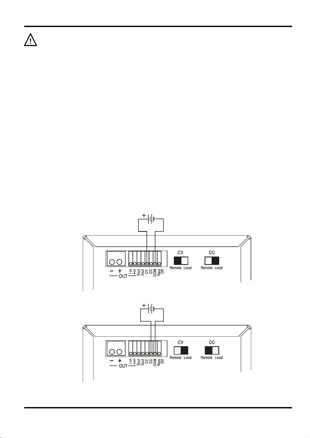
ACHTUNG Legen Sie zwischen den Klemmen CC bzw. CV keine externe Steuerspannung an,
die den Maximalwert des gewählten Bereichs (5V oder 10V) überschreitet. Zwar sind die
Eingänge gegen Überspannung geschützt, aber das Gerät versucht eine
Ausgangsspannung/Stromabgabe über dem maximalen Nennwert zu erzeugen, wenn die
Steuerspannung den Grenzwert überschreitet. Dies kann zu Folgeschäden führen. Sollte dieser
Zustand anhalten, kann der Ausgang durch OVP bzw. OCP ausgeschaltet werden (siehe
folgender Abschnitt).
OVP und OCP
OVP (Überspannungsschutz) und OCP (Überstromschutz) sind in der Firmware implementiert
und können nur eingerichtet und verwendet werden, wenn eine Fernsteuerung über die
Schnittstellen RS232, USB, LAN (LXI) oder GPIB stattfindet. Die Einstellung erfolgt in Schritten
von 10mV und 1mA mit einer typischen Ansprechzeit von 500ms.
Im lokalen Modus sind OVP und OCP zwar weiterhin aktiviert, jedoch fest auf 105% des
Maximalbereichs eingestellt. Damit wird ein Abschaltschutz gewährleistet, falls eine länger
anliegende CV oder CC Steuerspannung versucht den Ausgang über 105% des Maximalbereichs
zu setzen.
Praktische Überlegungen bei der Verwendung von CV und CC
Die Stabilität der Steuerspannungen wirkt sich direkt auf die Stabilität des Ausgangs aus.
Jegliche Störungen der Steuersignale resultieren in Störungen des Ausgangs. Um diese
möglichst gering zu halten verwenden Sie verdrillte oder abgeschirmte Leitungspaare (nur an
einem Ende geerdet) für den Anschluss der Steuerspannung an die CV, CC und COM Eingänge
und halten Sie die Verbindung so kurz wie möglich.
Die folgenden Zeichnungen zeigen die Anschlüsse für Konstantspannung (CV) und
Konstantstrom (CC) bei Verwendung einer externen Steuerspannung.
Konstantspannungssteuerung
Konstantstromsteuerung
93
Page 98
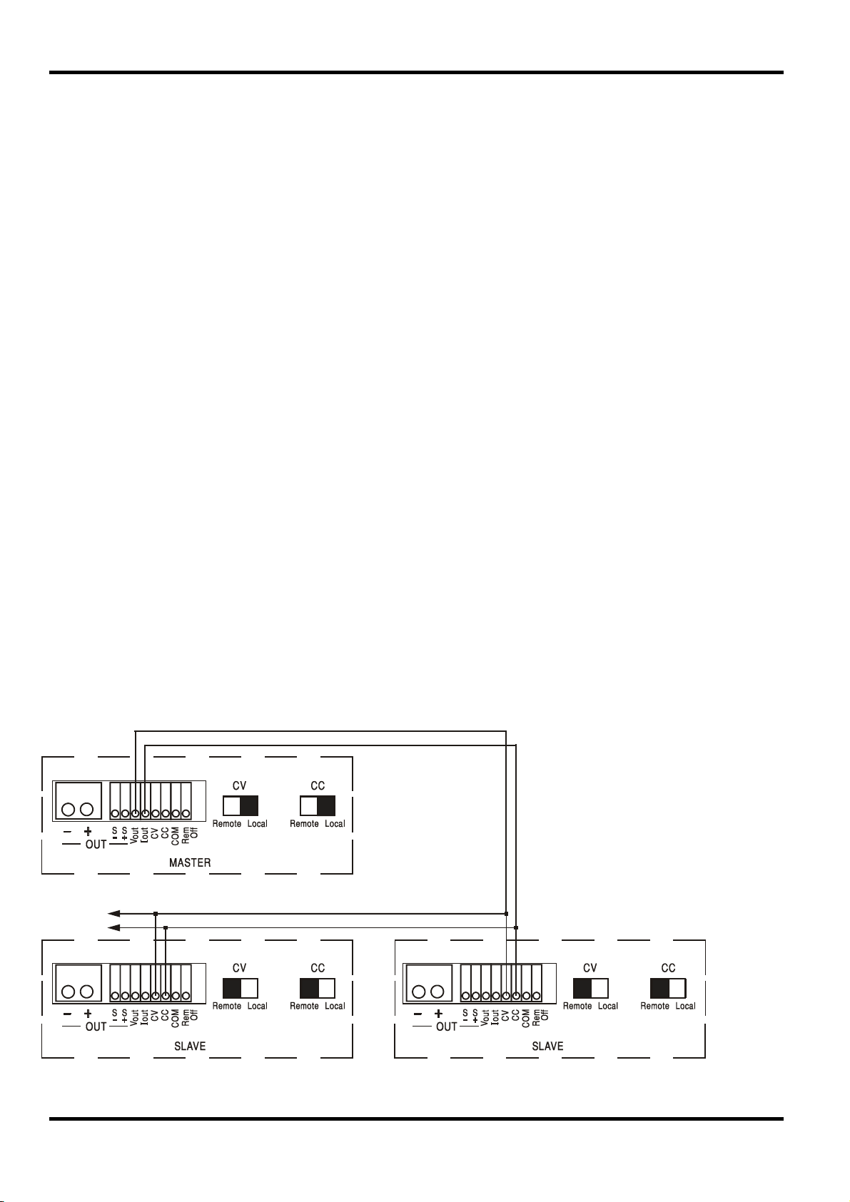
Bei eingeschaltetem OUTPUT zeigt das Display auf dem Gerät immer die aktuellen Werte für
Ausgangsspannung und Strom, ganz gleich welche Steuerungsquelle verwendet wird. Ist der
OUTPUT jedoch ausgeschaltet, zeigt das Display die mit den Reglern auf der Vorderseite
eingestellten Werte für Strom und Spannung an (oder die Werte der Digitalschnittstelle, falls aktiv)
und nicht die Werte für die CV und CC Eingänge, selbst wenn diese aktiv sind (CV und CC
stehen auf REMOTE). Um Verwechslungen zu vermeiden, sollten die vorderen Regler immer
ganz heruntergedreht sein, wenn CV und CC verwendet werden.
Steuerspannungen des Analogausgangs
Die Steuerspannungen V
und I
out
des Analogausgangs werden aus den aktuellen internen
out
Steuerspannungen erzeugt. Diese wiederum können von den Reglern auf der Gerätevorderseite,
von den digitalen Schnittstellen (RS232, USB, LAN oder GPIB) oder von den ferngesteuerten
Analogeingängen CV und CC stammen. V
Nennausgangsspannung und Strom (nur Hochstrombereich) 0V bis 5V an den Klemmen V
I
auf der Geräterückseite erzeugen (in Bezug auf COM). COM ist mit dem positiven Ausgang
out
verbunden.
entspricht immer dem eingestellten Strom, ganz gleich ob der Ausgang ein- oder
I
out
ausgeschaltet ist. Dagegen geht V
auf 0V, wenn der Ausgang ausgeschaltet wird.
out
Parallelbetrieb in Master-Slave Konfiguration
Der Parallelbetrieb in einer Master-Slave Konfiguration ermöglicht höhere Ausgangsströme mit
gleichmäßiger Stromverteilung zwischen den Geräten, wobei sowohl Strom als auch Spannung
von nur einem Gerät gesteuert werden. Alle Geräte müssen vom gleichen Typ sein (d. h.
identische Nennwerte für Ausgangsspanung und Strom). Das Diagramm zeigt 3 parallel
geschaltete Geräte. Um eine gleichmäßige Stromverteilung zu erreichen, muss jedes Gerät
getrennt an die Last gekoppelt werden, wobei identische Querschnitte und Leitungslängen
erforderlich sind, um den gleichen Spannungsabfall zu erreichen. Verbinden Sie V
Master-Geräts mit den CV und CC Eingänge der Slave-Geräte (siehe Abbildung). Setzen Sie die
Schalter CV und CC auf REMOTE.
Hinweis: Die COM Anschlüsse der Slave-Geräte bleiben unbelegt, da sie bereits über die
positiven Ausgangsanschlüsse mit dem Master verbunden sind.
Die Spannungs- und Stromeinstellung des Masters kann über die vorderen Regler, die digitale
Schnittstelle oder über eine externe Spannung an den CV und CC Steuereingängen erfolgen.
Parallelbetrieb in Master-Slave Konfiguration
und I
out
sind so skaliert, dass 0 bis 100% der
out
out
Hinweise:
1. Die Geräte können für CV (Konstantspannung,
CC (Konstantstrom) oder beide verdrahtet
werden(hier sind beide dargestellt). Setzen Sie
die CV bzw. CC Schalter beider Slave-Geräte auf
REMOTE.
2. Schließen Sie die Ausgänge parallel mit gleich
langen Kabeln an der Last an.
3. Wenn die Fernfühlerfunktion verwendet
werden soll, darf diese Verbindung nur zwischen
Master und Last hergestellt werden.
4. Für Konstantstrombetrieb muss die
erforderliche Gesamtspannung am Master
eingestellt werden.
und I
out
out
und
des
94
Page 99

Im Konstantspannungsbetrieb enstpricht die Spannung an der Last der auf dem Master
eingestellten Spannung (über Frontregler, Digitalschnittstelle oder CV-Steuereingang). Die
Strombegrenzung des Systems (d. h. der Strom im Konstantstrombetrieb) entspricht dem auf dem
Master eingestellten Strombegrenzungswert (x n), wobei n die Gesamtzahl der parallel
angeschlossenen Geräte ist.
Hinweis: Da die analogen Fernsteuereingänge nicht galvanisch getrennt sind (COM ist mit der
positiven Ausgangsklemme verbunden) kann die analoge Fernsteuerung nicht mit in Reihe
geschalteten Geräten verwendet werden.
Ferngesteuerte Abschaltung
Durch Schließen eines Schalters oder ein „Low“ Signal an den Anschlüssen REM OFF und COM
wird der Ausgang abgeschaltet. Die Leuchte OUTPUT auf der Gerätevorderseite erlischt
ebenfalls. Durch Öffnen des Schalters zwischen REM OFF und COM wird der Ausgang wieder
eingeschaltet.
95
Page 100

Bedienung der Fernschnittstelle
Das Gerät kann über seine RS232-, USB-, LAN- oder optionalen GPIB-Schnittstellen
ferngesteuert werden. Die analoge Fernsteuerung wurde im vorhergehenden Kapitel
beschrieben.
Die USB-Fernbedienung funktioniert genauso wie bei einem RS232, nur wird stattdessen der
USB-Anschluss verwendet. Die mit dem Gerät gelieferte Software richtet den steuernden
Computer darauf ein, den USB-Anschluss als virtuellen COM-Port zu behandeln. Die
Anwendungssoftware auf dem Computer kann dann über den COM-Port auf das Gerät zugreifen.
Die LAN-Schnittstelle entspricht LXI ( Lan eXtensions for Instrumentation) Version 1.2; das Gerät
ist Class C konform. Eine Fernsteuerung über die LAN-Schnittstelle ist über das TCP/IP Sockets
Protokoll möglich. Das Gerät enthält auch einen einfachen Web-Server mit Informationen zum
Gerät, der die Konfiguration von einem Web-Browser aus ermöglicht. Eine einfache
Befehlszeilensteuerung vom Browser aus ist ebenfalls möglich.
Das Gerät wird standardmäßig mit den Schnittstellen RS232, USB und LAN geliefert; GPIB ist als
Option verfügbar. Alle Schnittstellen sind standardmäßig zu jeder Zeit aktiviert (wie von der LXI
Spezifikation gefordert), der Zugang zu einzelnen Schnittstellen kann jedoch über die
Konfigurationsoptionen auf den Webseiten eingeschränkt werden.
Sperren der Schnittstellen
Alle Schnittstelle sind jederzeit aktiviert; dadurch braucht die aktive Schnittstelle nicht speziell
gewählt zu werden (siehe LXI Spezifikation). Damit das Gerät nicht versehentlich gleichzeitig von
zwei Schnittstellen gesteuert wird, enthält der Befehlssatz einen einfachen Sperr- und
Freigabemechanismus. Die Sperrung wird automatisch aufgehoben, wenn eine Trennung
festgestellt werden kann oder wenn die Taste „LOCAL“ gedrückt wird. Der Zugriff auf die
Schnittstellen kann auch über die Webseiten beschränkt werden.
Jede Schnittstelle kann durch Senden des Befehls „IFLOCK“ eine exklusive Steuerung des
Geräts anfordern. Die Sperre wird nur aufgehoben, wenn der Befehl „IFUNLOCK” von der aktuell
gesperrten Schnittstelle gesendet wird. Andere Schnittstellen können den Schnittstellen-Status
mit dem Befehl „IFLOCK?” abfragen. Die Antwort auf diese Befehle lautet „-1” wenn die Sperre
bereits von einer anderen Schnittstelle in Anspruch genommen wird, „0” wenn die Schnittstelle
frei ist und „1” wenn die die fragende Schnittstelle bereits gesperrt ist. Wird ein Befehl von einer
Schnittstelle ohne Steuerrechte gesendet, der versucht den Gerätestatus zu ändern, so wird Bit 4
des Standard Event Status Registers und 200 in das Execution Error Register gesetzt, um darauf
hinzuweisen, dass für die gewünschte Aktivität keine ausreichenden Rechte vorhanden sind.
Hinweis: Die Rechte für eine Schnittstelle können über die Webseite auch auf ‘schreibgeschützt’
oder ‘kein Zugriff’gesetzt werden.
Adressenauswahl
Die Adressierungsfähigkeit wird eigentlich nur von der GPIB Schnittstelle benötigt. Der
ADDRESS?-Befehl kann jedoch von allen Schnittstellen zur einfachen Identifizierung des von
einem bestimmten COM-Port (bei RS232 oder USB) bzw. TCP-Socket (bei LAN) gesteuerten
Geräts verwendet werden. Beachten Sie, dass die LAN Schnittstelle auch eine getrennte
Identifizierungsfunktion besitzt, die von der Webseite des Geräts aus zugänglich ist und dazu
führt, dass das Gerät so lange blinkt, bis der Befehl beendet wird.
Die Adresse wird auf der Gerätevorderseite wie folgt eingestellt. Bei zunächst ausgeschaltetem
Gerät die Tasten Lock, Meter Average und Current Range gedrückt halten (bei
Doppelnetzgeräten nur SLAVE Ausgang) und dann das Gerät einschalten. Im Display erscheint
Addr im Spannungsbereich und nn im mA-Bereich, wobei nn die aktuelle Einstellung ist
(Standardadresse
Range im Bereich 1 bis 31 inklusive (ohne 0) durchgehend erhöht oder verringert werden. Die
Adresse wird bestätigt und der Vorgang abgeschlossen, wenn Sie die Taste Lock drücken; das
Display zeigt etwa 2 Sekunden lang
Spannungs- und mA-Anzeige zurück, sobald die neue Adresse akzeptiert worden ist. Die
Adresse kann auch über die Webseite des Geräts eingestellt werden.
96
Addr 11). Der Adresswert kann mit den Tasten Meter Average und Current
SEt und die neue Adresse an, kehrt aber zur normalen
 Loading...