

Page 1

Type T Series Operation Manual
for T, T-1, T-1-CPF, T-2, T-3, and Systems F
Page 2

Contents
Overview ............................................................. 1
Introduction ............................................................1
Features and Parts Lists..................................................3
Safety Instructions ................................................ 6
Warnings, Cautions, and Notes...........................................6
Setup .................................................................. 7
Assembly ...............................................................7
Operation and Maintenance .................................... 9
Generating Pressure.....................................................9
Priming................................................................10
Connection Diagram ............................................. 13
Crystal Reference Indicators ............................................13
Specifications ...................................................... 14
Support .............................................................. 15
Troubleshooting .......................................................15
Fitting Kits and Spare Parts .............................................19
Appendix A: Assembly Drawings and Parts Lists..........................21
Contact Us.............................................................28
Returning product to AMETEK ..........................................28
Warranty ..............................................................28
Page 3

Overview
INTRODUCTION
The Type T Series hand pump, mounted on a drip pan with a manifold assembly, is capable of producing pressures up to 1000 bar/15 000 psi.
These units are self-contained pressure sources designed to test instruments. They may be used to calibrate pressure gauges or to set hydraulic relief valves
F
and pressure switches. These units produce pressure to test components or systems, and work independently of other pressure sources. CP
Crystal Pressure Fittings (CPF), which allow users to produce leak-free seals without tools or thread tape. CPF ttings also include a self-venting weep hole to
help assure a safe disconnection from a pressurized system.
U.S. Patent No. 8,794,677
T, T-1, and T-2 pumps1 may be ordered as part of a Pump System, complete with a JOFRA or Crystal Pressure Indicator. T-3 pumps ship as part of a complete
comparator testing kit, including four analog test gauges and necessary mounting tools and ttings, all housed in a rugged metal carrying case. For more
details on T-3 comparator testing kits, refer to T-3 Pumps for Hydraulic Comparator Kits on page 2.
All Type T Series Pump Systems include the most commonly used pressure ttings, seals, etc., all packaged in a carrying case with a custom insert.
1 T designates a pump only. T-1 designates a pump with a manifold and tools. T-2 designates a pump with manifold, tools, and a carrying case.
T, T-1, and T-2 Pumps
versions include
Overview 1
Pressure Medium O-rings
T-1 Water
T-1- CPF Oil or Water
T-1/VITON Water
T-1/EPT Water
T-1/OIL Oil Buna-N FOB
T-1/OIL/VITON Oil Viton® FOV
T-1/OIL/EPT Oil EPT
*
Water is a 50/50 mixture of water and Isopropyl Alcohol.
*
*
*
*
Buna-N
Viton® FOV or FWV
Viton® FWV
EPT FWE
Pump System
FWB
FOE
Type T Series Pump System
Type T Pump Operation Manual
Page 4
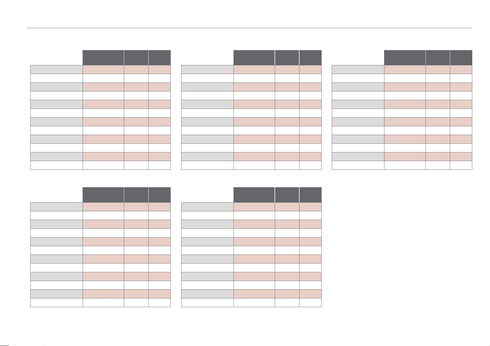
T-3 Pumps for Hydraulic Comparator Kits
Overview 2
X
With 160, 600, 5000, and 10 000 psi Gauges
Cal. Certication
with Data
T-3
T-3/EPT
T-3/VITON
T-3/OIL
T-3/OIL /EPT
T-3/OIL/VITON
T-3/C
T-3/C/EPT
T-3/C/VITON
T-3/C/OIL
T-3/C/OIL /EPT
T-3/C/OIL/VITON
X
With 30, 600, 3000, and 5000 psi Gauges
No Water
No Water
No Water
No Oil Buna-N
No Oil EPT
No Oil VITON
Yes Water
Yes Water
Yes Water
Yes Oil Buna-N
Yes Oil EPT
Yes Oil VITON
Cal. Certication
with Data
T-3A
T-3A/EPT
T-3A/VITON
T-3A/OIL
T-3A/OIL/EPT
T-3A/OIL/VITON
T-3A/C
T-3A/C/EPT
T-3A/C/VITON
T-3A/C/OIL
T-3A/C/OIL/EPT
T-3A/C/OIL/VITON
No Water
No Water
No Water
No Oil Buna-N
No Oil EPT
No Oil VITON
Yes Water
Yes Water
Yes Water
Yes Oil Buna-N
Yes Oil EPT
Yes Oil VITON
Pressure
Medium
Pressure
Medium
X
With 2, 42, 210, and 350 kg/cm² Gauges
O-rings
*
Buna-N
*
EPT
*
VITON
T-3AM
T-3AM/EPT
T-3AM/VITON
T-3AM/OIL
T-3AM/OIL/EPT
T-3AM/OIL/VITON
*
Buna-N
*
EPT
*
VITON
T-3AM/C
T-3AM/C /EPT
T-3AM/C/VITON
T-3AM/C /OIL
T-3AM/C /OIL/EPT
T-3AM/C/OIL/VITON
X
With 200, 4000, 21 000, and 35 000 kPa gauges
O-rings
*
Buna-N
*
EPT
*
VITON
T-3AN
T-3AN/EPT
T-3AN/VITON
T-3AN/OIL
T-3AN/OIL /EPT
T-3AN/OIL/VITON
*
Buna-N
*
EPT
*
VITON
T-3AN/C
T-3AN/C/EPT
T-3AN/C/VITON
T-3AN/C/OIL
T-3AN/C/OIL/EPT
T-3AN/C/OIL/VITON
Cal. Certication
with Data
No Water
No Water
No Water
No Oil Buna-N
No Oil EPT
No Oil VITON
Yes Water
Yes Water
Yes Water
Yes Oil Buna-N
Yes Oil EPT
Yes Oil VITON
Cal. Certication
with Data
No Water
No Water
No Water
No Oil Buna-N
No Oil EPT
No Oil VITON
Yes Water
Yes Water
Yes Water
Yes Oil Buna-N
Yes Oil EPT
Yes Oil VITON
Pressure
Medium
*
*
*
*
*
*
Pressure
Medium
*
*
*
*
*
*
O-rings
Buna-N
EPT
VITON
Buna-N
EPT
VITON
O-rings
Buna-N
EPT
VITON
Buna-N
EPT
VITON
X
With 11, 42, 350, and 700 bar gauges
Cal. Certication
with Data
T-3/BARS
T-3/BARS/EPT
T-3/BARS/VITON
T-3/BARS/OIL
T-3/BARS/OIL/EPT
T-3/BARS/OIL/VITON
T-3/BARS/C
T-3/BARS/C/EPT
T-3/BARS/C/VITON
T-3/BARS/C/OIL
T-3/BARS/C/OIL/EPT
T-3/BARS/C/OIL/VITON
*
Water is a 50/50 mixture of water and Isopropyl Alcohol.
No Water
No Water
No Water
No Oil Buna-N
No Oil EPT
No Oil VITON
Yes Water
Yes Water
Yes Water
Yes Oil Buna-N
Yes Oil EPT
Yes Oil VITON
T-3 Hydraulic
Comparator Testing Kit
Pressure
Medium
*
*
*
*
*
*
O-rings
Buna-N
EPT
VITON
Buna-N
EPT
VITON
Type T Pump Operation Manual
Page 5
FEATURES AND PARTS LISTS
Type T Series hand pumps may be ordered with either oil or a water/alcohol mixture as the pressure medium. There are three available seal packages for the
system: Buna-N, Viton®, and EPT.
All Type T Series hand pumps feature a vent valve, and dual volume control for rapid pressure increase at lower pressures and easier pumping at higher
pressures. T-1,
T-2, and T-3 models include a dual pressure port manifold with ne adjust, plus replacement o-rings and a set of service tools.
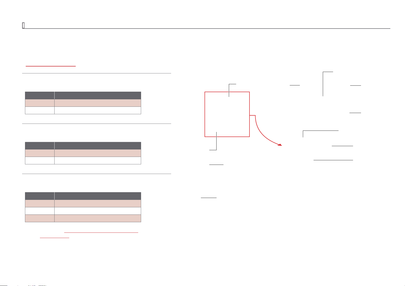
Refer to Figure 3 on page 25 for more details on the included tools.
T-1 and T-2 – Included Parts
X
Reference and Device Under Test Pressure Ports
Part Number Description
T-134 15/16-20 Male to 1/4" NPT Female Adapter
T-135 15/16-20 Male to 1/2" NPT Female Adapter
Check Valve Plug
CPF Fitting
Overview 3
Fine Adjust
NPT Union Body
Manifold Assembly
T-1-CPF – Included Parts
X
Reference and Device Under Test Pressure Ports
Part Number Description
5255 CPF Male to 15/16-20 Male Adapter (2)
4715 MP Female to 1/4" Female NPT Fitting
T-3 – Included Parts
X
Reference and Device Under Test Pressure Ports
Part Number Description
T-134 15/16-20 Male to 1/4" NPT Female Adapter
T-135 15/16-20 Male to 1/2" NPT Female Adapter
– Set of 4 Test Gauges
*
For more details refer to T-3 Pumps for Hydraulic Comparator Kits on page 2
and to Figure 4 on page 26.
*
Fill and Vent Relief Plug
Vent Valve
Valve Rod Selector
Check Valve Plug
Pump Handle
Reservoir Tube
Type T Pump Operation Manual
Page 6
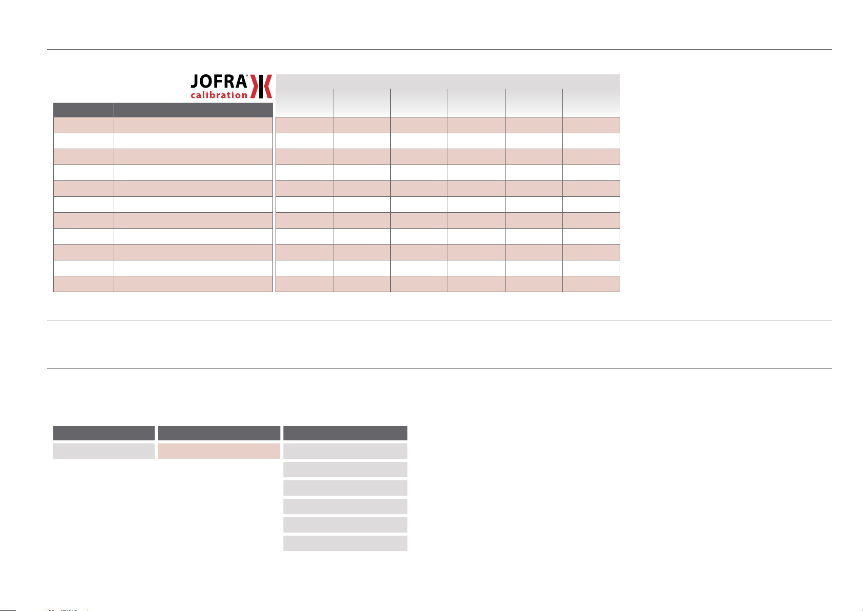
Parts Included with Pump Systems for JOFRA Reference Indicators
Part Number Description
T-134 15/16-20 Male to 1/4" NPT Female Adapter
T-135 15/16-20 Male to 1/2" NPT Female Adapter
T-786 1/4" NPT Male to 1/4" BSP Female Fitting
*
1274 00
*
1274 01
*
1274 02
60 R120 1/4" Bonded Seals
*
404203
60I104 Pack Tape (1 roll)
124004 Shoulder Strap
12430 4 Aluminum Carrying Case
*
Included with HPC.
1/4" NPT Male to 1/8" BSP Male Fitting
1/4" BSP Female to 1/8" BSP Male Fitting
1/8" Bonded Seals
Test Leads; Red & Black, including clips
FWB
(T-1)
FWV
(T-1/Viton)
FWE
(T-1/EP T)
System F
FOB
(T-1/Oil)
FOV
(T-1/O il/Viton)
Overview 4
FOE
(T-1/Oil/EPT)
Hydraulic Fluid
Type T Series Pump Systems are only available delivered empty. You will still need to specify what uid type you are going to use (for example; FOV for Oil or FWV for Water).
Ordering a Pump System
Any Type T Series Pump System may be ordered with or without a reference indicator. The table below provides an explanation of the Pump System ordering
scheme when ordering a system without an indicator. For details on ordering the Pump Systems with an indicator, see the indicator datasheet.
X
Reference Indicator Reference Indicator Included Pump System
HPC500 Series ...HPC500 No ...-NONE System F (T-1) .............-FWB
System F (T-1/Viton) .......-FWV
System F (T-1/EPT) ........-FWE
System F (T-1/Oil) .........-FOB
System F (T-1/Oil/Viton) ...-FOV
System F (T-1/Oil/EPT) .....-FOE
SAMPLE PART NUMBERS
HPC-NONE-FWB ..........System F pump system (for HPC500), for use with water.
HPC-NONE-FOE ...........System F pump system (for HPC500), for use with oil.
HPC500-700G-FOB ........System F pump system for use with oil with a 0.82 to 35 bar HPC500 included.
Type T Pump Operation Manual
Page 7
Overview 5
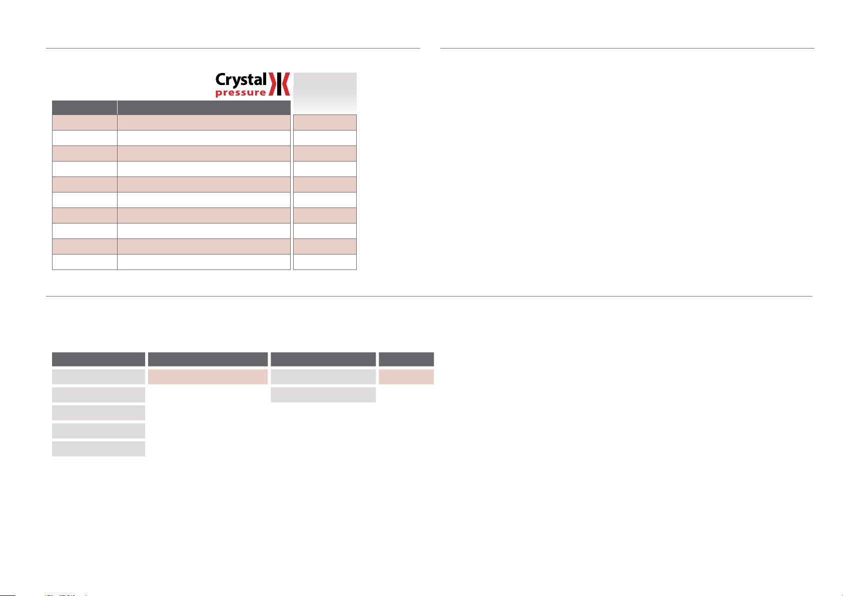
Parts Included with Pump Systems for Crystal Reference Indicators
System F
FOV and FWV
Part Number Description
5255 CPF Male to 15/16-20 Male Adapter
MPF15K-1/4F PT CPF Female to 1/4" NPT Female Fitting
MPF-1/4BSPF CPF to 1/4" BSP Female Fitting
MPF-1/8MPT
60 R120 1/4" Bonded Seals
1351
5249
60I104 Pack Tape (1 roll)
124004 Shoulder Strap
12430 4 Aluminum Carrying Case
*
The MPF-1/8MPT ttings and 1351 Test Leads are included only with Pump Systems for the 30 Series Calibrator.
*
1/8" MPT Fitting (for 30 Series Calibrator)
*
Test Leads; Red & Black, including clips
Protective Vinyl Cap
(T-1- CPF)
(2 )
(2 )
( 5 )
( 4 )
Hydraulic Fluid
Type T Series Pump Systems are only available delivered empty. You will still need to specify what uid
type you are going to use (for example; FOV for Oil or FWV for Water).
Ordering a Pump System
Any Type T Series Pump System may be ordered with or without a reference indicator. The table below provides an explanation of the Pump System ordering
scheme when ordering a system without an indicator. For details on ordering the Pump Systems with an indicator, see the indicator datasheet.
Reference Indicator Reference Indicator Included Pump System Liquid
nVision ......... NV No ...-NONE System F (T-1-CPF) ... -FOV Drained ...-E
30 Series ........IS30 System F (T-1-CPF) ... -FWV
XP2i ............XP2i
m1 .............. M1
HPC40 Series ...HPC40
X
SAMPLE PART NUMBERS
NV-NONE-FOV-E .......System F pump system (for nVision) drained of uid, for use with oil.
IS30-NONE-FWV-E ....System F pump system (for 30 Series) drained of uid, for use with water.
15KPSIXP2i-FWV-E ...System F pump system, drained, for use with water, with a 15 000 psi XP2i gauge included.
Type T Pump Operation Manual
Page 8

Safety Instructions
WARNINGS, CAUTIONS, AND NOTES
WARNINGS:
!
Do not connect any external pressure source to this instrument. This unit is designed to test pressure measuring devices connected to the manifold
•
only. Pressure from an external source can result in explosion of the liquid reservoir and possible bodily injury.
This pump produces pressure up to 15 000 psi. The pressure rating of tubing and ttings used to connect the pump to the test device should exceed
•
15 000 psi.
Do not operate above 15 000 psi/1000 bar.
•
CAUTIONS:
!
To prevent the reservoir from overowing upon venting, the volume of oil pumped should never exceed the reservoir volume.
•
Never operate the pump without uid in the reservoir. The piston and o-rings require lubrication.
•
Do not operate the ne adjust knob above 3500 psi.
•
The vent plug must be open to operate this instrument.
•
Notes: All wetted parts are stainless steel, Monel, or Buna-N. Optional o-ring materials are Viton and EPT .
Safety Instructions 6
Type T Pump Operation Manual
Page 9
Setup
ASSEMBLY
1 Open the vent valve.
2 Attach the pressure manifold to the pump body.
Setup 7
Manifold Assembly
Type T Pump Operation Manual
Page 10

3 Close the vent valve.
Note: If using the T-1-CPF, ll with test uid through the gauge connections. This may take approximately 15 minutes.
Setup 8
Note: It may be necessary to prime the pump, particularly for rst time use, or if the pump has been inactive for an extended period of time.
Refer to Priming on page 10 for instructions on priming the pump.
Pull the pump handle to the top of its stroke.
4
5 Pull out the valve rod selector to select the low pressure/high volume setting.
6 Gently operate the pump handle until test uid lls the top of the pressure ports on the pressure manifold.
Note: Lightly tap the manifold to make sure that any air bubbles sticking to the walls or in low ow areas are released to oat to the surface.
7 Attach the reference instrument and the device under test to the manifold.
Note: If CPF Fittings are used in your pressure system, remaining air can be purged by applying 10 psi or less and loosening the CPF tting closest to the pres
sure device. When uid and air escape from the CPF weep hole, that portion of the system is purged. Repeat this process for each pressure device in the
essur
e system which is connected to a CPF tting.
pr
-
CAUTION: Always choose a reference instrument with a range equal to or greater than the range of the device under test.
!
8 Ensure all connections are tight and leak free.
Type T Pump Operation Manual
Page 11

Operation and Maintenance
GENERATING PRESSURE
Note: It may be necessary to prime the pump, particularly if the pump has been inactive for an extended period of time. Refer to Priming on page 10
for instructions on priming the pump.
Check that the vent ll plug is fully open by turning it counter-clockwise.
1
2 Open the vent valve.
Operation and Maintenance 9
Open the vent plug… then open the vent valve.
3 Set the valve rod selector to control your desired uid output volume.
Low Pressure/
High Volume
CAUTION: Only move the valve rod selector while the pump handle is stationary, in the up position.
!
Note: With the valve rod in the “out” position, uid ow will be at maximum and the maximum achievable pressure will be 1000 psi. To exceed 1000 psi,
push the valve rod in.
High Pressure/
Low Volume
Type T Pump Operation Manual
Page 12

4 Zero the reference indicator and the device under test.
5 Close the vent valve.
6 Operate the pump handle to achieve a system pressure close to, but less than, your desired target pressure.
7 Pull the pump handle to the top of its stroke.
8 Push in the valve rod selector to select the high pressure/low volume setting.
9 Wait for the pressure to stabilize.
10 Carefully push down the pump handle to achieve the target pressure.
Note: Below 3500 psi, you may also use the ne adjust knob for small pressure adjustments.
11 After obtaining your readings, open the vent valve to vent the system.
WARNING: The device under test and the reference indicator should only be removed when there is no pressure in the system.
!
PRIMING
All pumps are thoroughly tested at the factory before shipment. One of the most common diculties encountered is the loss of prime, which is evidenced by
an inability to build pressure. This is caused by entrapped air in the reservoir, which may collect in the high pressure/low volume check valve. When this occurs, the pump will not develop pressure with the valve rod selector positioned in, to the high pressure/low volume setting. The following priming procedure
or
rect the condition.
will c
Operation and Maintenance 10
Note: For priming purposes, pump vigorously with full strokes of the hand lever.
Note: Verify the pump reservoir has sucient uid.
X
To Prime the Pump
1 Connect a reference indicator with a pressure range of at least 5000 psi to the manifold.
CAUTION: Signicant pressure can develop during the priming process. Therefore, any device mounted to the manifold should have a range of at least
!
2 Plug the remaining port of the manifold.
300 bar / 5000 psi. Alternately, all devices may be removed, and the manifold plugged.
Manifold Plug
Type T Pump Operation Manual
Page 13

3 Pull the pump handle to the top of its stroke.
4 Open the vent valve.
5 Pull out the valve rod selector to select low pressure/high volume.
Open the vent valve… then select low pressure/high volume.
6 Pump ten full strokes.
7 Close the vent valve
Operation and Maintenance 11
8 Continue pumping to verify the low pressure/high volume setting operates properly and that the pump holds pressure.
9 Open the vent valve.
10 Pump ten more strokes.
11 Remove the high pressure/low volume check valve plug.
Type T Pump Operation Manual
Page 14

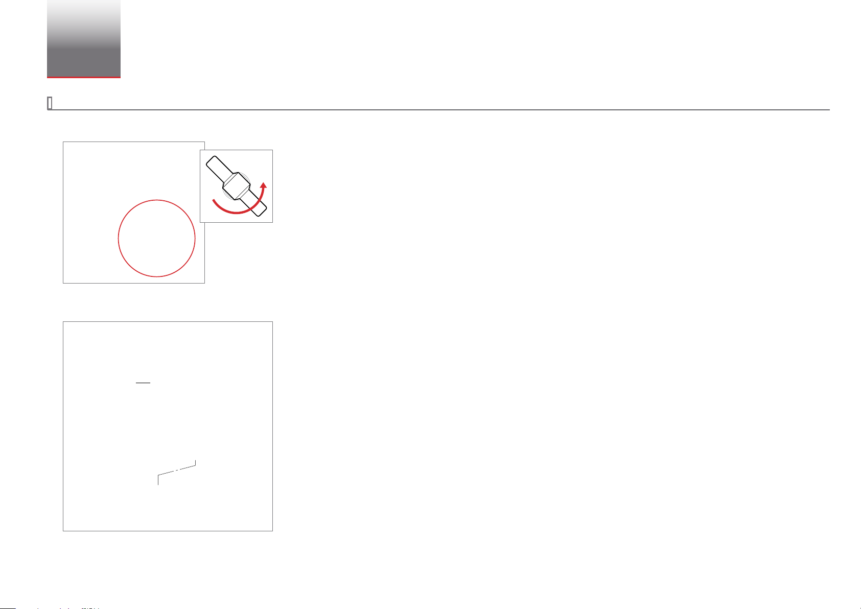
12 Slowly pump two and one-half strokes, positioning the pump lever at approximately 45 degrees, halfway through its stroke.
13 Allow system uid to ow out of the high pressure check valve, ushing entrapped air.
14 Examine the port for air bubbles which may adhere to the threads or parts.
Note: If air bubbles are present, repeat steps 12 through 14 until no more air bubbles appear.
15 Replace the high pressure/low volume check valve plug and tighten partially.
Operation and Maintenance 12
16 Use slight pressure on the hand lever to push system uid past the high pressure/low volume check valve plug to ensure complete purging of the
valve port.
Tighten the high pressure/low volume check valve plug.
17
18 Operate the pump handle until pumping becomes dicult.
19 Raise the pump handle.
20 Push in the valve rod selector to the high pressure/low volume position.
21 Resume pumping to verify the pump is operating properly.
Note: If the high pressure/low volume setting does not operate properly, there is more air trapped in the high pressure/low volume check valve. The priming
procedure must be repeated.
Type T Pump Operation Manual
Page 15

Connection Diagram
CRYSTAL REFERENCE INDICATORS
Thread tape
required.
MPF-1/8MPT
10
Connection Diagram 13
CPF Fittings Non-CPF MP Fittings
NPT MALE
NPT FEMALE
BSP
MPF-1/8QTM 1/8" Quick Test NPT Male
MPF-1/8MPT 1/8" NPT Male
MPF-1/4QTM 1/4" Quick Test NPT Male
MPF-1/4MPT
Additional N PT sizes available in non- CPF MP adapters
MPF-1/8QTF 1/8" Quick Test NPT Female
MPF-1/4QTF 1/4" Quick Test NPT Female
MPF-1/4FPT 1/4" NPT Female
MPF-1/2QTF 1/2" Quick Test NPT Female
Additional N PT sizes available in non- CPF MP adapters
MPF-1/8BSPF G 1/8" Female
MPF-1/4BSPF G 1/4" Female
MPF-3/8BSPF G 3/8" Female
MPF-1/2BSPF G 1/2" Female
1/4" NPT Male
Medium Pressure FEMALE to NPT FEMALE
10
10
10
10
4501 1/8 NPT
4715
*
4502 3/8 NPT
4503
Medium Pressure FEMALE to NPT MALE
10
10
10
5
4714 1/4 NPT
4494 3/8 NPT
4495 1/2 NPT
4496 3/4 NPT
Medium Pressure MALE to NPT FEMALE
10
10
10
10
4497 1/8 NPT
4498 1/4 NPT
4499 3/8 NPT
4500 1/2 NPT
1/4 NPT
1/2 NPT
15
15
15
15
15
15
15
10
15
15
15
15
15
5255 *
TRANSMITTER
MPF-5/16TRM
MPF-1/4TRM for Honey well
15
5255 *
TUBE
MPF-1/4TBM 1/4" Tube Male
MPF-3/8TBM 3/8" Tube Male
MPF-1/2TBM 1/2" Tube Male
CPF
MPF-MPF Female to Female
MPF-MPFT U T-Union (Female)
MPF-MPFBULK Bulkhead (Female to Female)
MPF-CAP Cap
ADDITIONAL
MPF-M20QTF M20 x 1.5 Quick Test Female
MPF-M20X1.5F M20 x 1.5 Female
MPF-QCN Quick-Connect Nut
MPF-AN4M AN4 Male
* These parts are included with the T-1-CPF pump.
Additional parts are supplied as part of a pump system, or may be ordered separately.
All BSP connections require bonded seals.
for Foxboro, Rosemount,
and Yokogawa
Medium Pressure MALE to NPT MALE
5
5
5
5
5
5
300 bar/5000 psi
10
700 bar/10 000 psi
10
15
10
10
10
5
10
5
5
1000 bar/15 000 psi
(Non-CPF MP adapters require wrench tightening.)
4698 1/4 NPT
4492 3/8 NPT
4493 1/2 NPT
Type T Pump Operation Manual
15
15
15
Page 16

Specifications
Pressure Ranges
T, T-1, T-1-CPF, T-2, and T-3 . . . . . . .0 to 1000 bar / 0 to 15 000 psi
Recommended Test Fluids
The following uids are recommended for use with this pump:
Standard .............................Distilled water or Isopropyl alcohol
Optional .............................. MGAAA oil
Other uids compatible with stainless steel, Monel, Buna N and Teon may be used. Optional Viton and EPT o-rings are available.
Volume ............................... 30 oz (887 mL)
Low Volume / High Pressure Setting ... 2.8 to 3.2 cc per stroke
High Volume / Low Pressure Setting ... 3.0 to 4.0 cc per stroke
Pressure Connections
Specications 14
X
Reference Port
T-1, T-2, and T-3 . . . . . . . . . . . . 1/4" FNPT or 1/2" FNPT
T-1-CPF . . . . . . . . . . . . . . . . . . . . CPF Male
X
Device Under Test Port
T-1, T-2, and T-3 . . . . . . . . . . . . 1/4" FNPT or 1/2" FNPT
T-1-CPF . . . . . . . . . . . . . . . . . . . . 1/4" Female NPT
Note: Additional sizes, including metric ttings, are available. Contact us, or see our CPF datasheet for details.
Dimensions
Pump . . . . . . . . . . . . . . . . . . . . . 224 (L) x 127 (W) x 217 (H)* mm.
Weight . . . . . . . . . . . . . . . . . . . . 18.6 lbs / 8.4 kg
*
Height includes manifold.
Type T Pump Operation Manual
Page 17

Support
TROUBLESHOOTING
Failure to Pump
X
Problem: The pump fails to develop pressure when the hand lever is operated.
X
Solution: Verify that the vent valve is closed and that there is sucient uid in the reservoir. If necessary, add uid through the ll plug and follow the Pump
Priming Procedure.
If the failure continues, one or both of the check valves may be leaking. Use the following procedure to replace both the high pressure and low pressure o-rings.
X
To Replace the Check Valve O-rings
1 Raise the pump handle to the top of its stroke.
2 Position the valve rod selector for the o-ring you wish to replace.
(a) Pull out the valve rod selector to select the low pressure/high volume setting.
(b) Push in the valve rod selector to select the high pressure/low volume setting.
3 Remove the plug and o-ring from the port for the check valve o-ring you wish to replace.
Support 15
Low pressure/high volume check valve plug and o-ring. High pressure/low volume check valve plug and o-ring.
Type T Pump Operation Manual
Page 18

4 Remove the check valve spacer, spring, valve poppet, and check valve o-ring.
Check Valve O-ring
Valve Poppet
Spring
Check Valve Spacer
5 Inspect the check valve o-ring, and replace it if necessary. Then re-install the o-ring, valve poppet, spring, and check valve spacer.
6 Slowly pump two and one-half strokes, positioning the pump lever at approximately 45 degrees, halfway through its stroke.
7 Allow system uid to ow out of the low pressure check valve, ushing entrapped air.
8 Examine the port for air bubbles which may adhere to the threads or parts.
Note: If air bubbles are present, repeat steps 2 through 5 until no more air bubbles appear.
Support 16
9 Install the check valve plug and o-ring and tighten partially.
10 If installing the low pressure/high volume check valve plug... Tighten the check valve plug.
The procedure for the low-pressure/high volume side is now complete.
11 If installing the high pressure/low volume check valve plug... Use slight pressure on the hand lever to push system uid past the high
pressure/low volume check valve plug to ensure complete purging of the valve port.
Tighten the high pressure/low volume check valve plug.
12
13 Operate the pump handle until pumping becomes dicult.
14 Raise the pump handle to the top of its stoke.
15 Push in the valve rod selector to the high pressure/low volume position.
16 Resume pumping to verify the pump is operating properly.
Type T Pump Operation Manual
Page 19

Pump Does Not Hold Pressure
Retaining Plug
X
Problem: The pump operates but the pressure declines beyond normal adiabatic eects.
X
Solution: One of two o-rings may be leaking. As the pressure drops, observe the hand lever. If the hand lever rises, the discharge check valve is leaking and
its o-ring should be replaced.
X
To Replace the Discharge Check Valve O-ring
1 Remove the plug and o-Ring from the front of the pump body.
Support 17
2 Use a screwdriver to loosen and remove the retaining plug. then remove the guide rod, spring, valve poppet and check valve o-ring.
Check Valve O-ring
Valve Poppet
Spring
Guide Rod
3 Inspect the check valve o-ring, and replace it if necessary. Then re-install the o-ring, valve poppet, spring, and guide rod.
4 Thread in the retaining plug until it is tightly seated. Then back o 3 ½ turns to provide sucient travel for the valve poppet.
5 Install the check valve plug and o-ring.
Type T Pump Operation Manual
Page 20

X
To Replace the Vent Valve O-ring
1 Apply a wrench to the nut at the base of the pressure relief valve.
2 Remove the vent valve and its o-ring.
3 Remove the relief valve seat and its o-ring.
Support 18
Relief Valve Seat O-ring
Relief Valve Seat
4 Inspect the relief valve seat o-ring, and replace it if necessary. Then re-install the o-ring, valve poppet, spring, and guide rod.
5 Install the vent valve and o-ring.
Type T Pump Operation Manual
Page 21

FITTING KITS AND SPARE PARTS
Service Kits
Support 19
X
T, T-1, T-2, and T-3
T-250 .............Buna N rebuild kit
T-559 .............Viton rebuild kit
T-326 .............EPT rebuild kit
Hoses
X
T-1
KH-18 .............Hose. 0.46 m 1/4" NPT male x 1/4" NPT male 700 bar / 10 000 psi.
Adapters
X
T-1, T-2, and T-3
T-134 ..............Union Body. 15/16-20 UNEF male x 1/4" NPT female.
T-135 ..............Union Body. 15/16-20 UNEF male x 1/2" NPT female.
T-186 ..............Union Body. 15/16-20 UNEF male x 7/16" NPT female.
T-331 ..............Union Body. 15/16-20 UNEF male x 3/8" NPT female.
T-863 ..............Union Body. 15/16-20 UNEF male x 1/8" NPT female.
T-786 ..............Adapter. 1/4" NPT male x 1/4" BSP female.
X
T-1-CPF
T-559 ..............Viton rebuild kit
X
T-1-CPF
MPH-1. . . . . . . . . . . . .1 meter CPF hose. 700 bar / 10 000 psi.
X
T-1-CPF
Refer to the Connection Diagram on page 13 for a complete list of adapters.
T-787 ..............Adapter. 1/4" NPT male x 1/2" BSP female.
T-915 ..............Quick Connector. 1/4" NPT male.
T-916 ..............Quick Connector Plug. 1/4" NPT male.
Type T Pump Operation Manual
Page 22

Frequency of Recertication
Four test gauges are included with each T-3 Comparator. Gauges rated up to 5000 psi / 350 bar / 21000 kPa / 210 kg/cm2 are 0.25% of full scale. Gauges rated
2
at 10 000 psi / 700 bar / 35000 kPa / 350 kg/cm
are 0.5% of full scale. All of the gauges can be ordered with or without calibration certicates. For detailed
information on the gauges refer to Figure 4 on page 27.
As a general rule, AMETEK, M&G test gauges should be tested and recertied every 12 months. Testers used frequently, or with dirty uids, should be tested
and certied at more frequent intervals. Master units, used infrequently with clean uid, may need to be tested and certied less frequently.
Note: It is not necessary to send in the pump if it is operating properly. Pumps may be refurbished at a nominal charge.
Note: In order to reduce process time and your overall cost, please do not send in any customized ttings, hoses, tools, or small miscellaneous parts.
Certication Options for New and Used Comparators
Before ordering a new T-3 comparator or sending an old comparator back to M&G, specify one of the following certication options and any
additional requirements on your purchase order. Contact your distributor if you need any assistance.
Option Description Details
A Standard certication of accuracy traceable to NIST standards. Item is repaired and calibrated. No data is provided.
Options with Additional Cost
B "With Data" — Option A Plus Data. Item is repaired and calibrated. Data is provided.
C "As Received/As Left" — Data plus Option A.
Item is cleaned and tested with no adjustments or repairs. Then the item is adjusted
or repaired and recalibrated if necessary.
Support 20
Type T Pump Operation Manual
Page 23

APPENDIX A: ASSEMBLY DRAWINGS AND PARTS LISTS
X
Figure 1.1 • Hydraulic Hand Pump Type T Assembly
Support 21
5 ( pg 25)
Detail A
Detail B ( pg 22)
Detail C
( pg 23)
6
7
8
Detail A
7
1
2
3
9
10
11
4
Type T Pump Operation Manual
Page 24

X
Figure 1.2 • Hydraulic Hand Pump Type T Assembly
12
Support 22
25
26
27
**
*
Detail B
The pump handle and piston can be removed as an
*
assembly for inspection of the o-rings and backup rings.
Remove the upper clevis pin (15) and cotter hair pin (17).
Then unscrew the cylinder retaining plug (18) and pull
the assembly straight up.
At the bottom of the pressure stroke, the piston should
rest on the body plate liner (29) before the pump handle
hits the cylinder retaining plug. If it does not, loosen the
piston pin screw (14), insert a small rod in the hole
provided at the top of the piston, and rotate the piston
counterclock-wise to raise the pump handle. When the
pump handle is raised to the proper height, tighten the
piston pin screw.
The pump cylinder must be removed and reassembled
**
from the top. Otherwise, the o-rings may be cut by the
angular, intersecting hold in the lower portion of the
pump body casting bore. To remove the cylinder, rst
detach the body plate (30) and body plate liner (29), then
push the cylinder up and out from the bottom.
On reassembly, moisten the o-rings with system uid and
rotate the cylinder as you insert it, to avoid cutting or
pinching the o-rings. A tapered piece of wood may be
helpful to rotate the cylinder.
13
14
15
16
19
17
18
20
21
22
23
24
26
25
28
29
18
30
31
16
(17)
Type T Pump Operation Manual
Page 25

X
Figure 1.3 • Hydraulic Hand Pump Type T Assembly
Support 23
38
37
36
35
44
33
32
Detail D
51
Detail D
Detail C
54
33
34
35
36
37
38
26
14
23
42
41
39
40
33
44
35
45
46
*
47
48
52
53
49
50
**
43
14
Thread in the retaining plug until all parts are solid. Then back o about 3 1/2 turns to provide sucient travel for the poppet.
*
The valve rod is held in place with parts 49, 50, and 51. Access to these parts is gained by rst draining the uid, then removing the reservoir.
**
Type T Pump Operation Manual
Page 26

X
Figure 1.4 • Hydraulic Hand Pump Type T Assembly Parts List
Support 24
Item
Number
1 – Type T Pump Assy 1
2 01-90007 Screw, Drip Pan Attaching 4
3 T-167 Washer, Drip Pan Attaching 4
4 T-118 Drip Pan 1
5 T-149 Manifold Assembly (see page 32) 1
6 T-328 Cap, Reservoir 1
7 10-90010 O-ring, Reservoir Tube (T-156) 2
8 T-131 Tube, Reservoir 1
9 T-130 Stud, Reservoir 1
10 T-140 Tube, Inlet 1
11 12-90152 Fitting, Inlet Tube 1
12 T-165 Handle, Pump 1
13 T-145 Pin, Piston 1
14 T-161 Shoe, Piston Pin 1
15 T-16 0 Screw, Piston Pin 3
16 T-142 Pin, Clevis 2
17 T-143 Clevis 1
18 T-14 4 Hair Pin, Cotter 2
19 T-10 8 Plug, Cylinder Retaining 1
20 10 -90019 Back-up Ring, Piston (T-158) 1
21 10-90006 O-ring (T-154) 1
22 T-10 6 Piston 1
23 10-90005 O-ring (T-151) 2
24 10-90018 Back-up Ring, Piston (T-159) 1
25 10-90020 Back-up Ring, Cylinder (T-112) 2
26 10-90 013 O-ring (T-153) 3
27 T-236 Cylinder, Pump 1
28 10 -90012 O-ring, Cylinder (T-164) 1
29 T-595 Liner, Body Plate 1
30 T-408 Plate, Body 1
31 01-90004 Screw, Body Attaching 3
32 IGT-302 Plug and Spacer, Fill and Vent Relief Assy 1
Part
Number
Description
Units Per
Assembly
Item
Number
33 10-90001 O-ring (T-152) 3
34 T-194 Poppet, Valve 1
35 C V-1-5 Spring, Check Valve 3
36 T-127 Spacer, Check Valve 2
37 10-90027 O-ring (T-154) 2
38 T-117 Plug, Pump Body 2
39 10-90002 O-ring (T-175) 1
40 T-111 Seat, Relief Valve 1
41 T-10 9 Body, Relief Valve 1
42 10-110 Stem, Relief Valve 1
43 T-773 Handle, Relief Valve 1
44 T-147 Poppet, High Pressure Valve 2
45 T-107 Guide Rod 1
46 T-141 Plug, Retaining 1
47 10-90009 O-ring (T-136) 1
48 T-103 Plug 1
49 T-166 Screw 1
50 T-116 Spring, Valve Rod 1
51 T-133 Detent Pin, Valve Rod 1
52 10-90004 O-ring 1
53 T -115 Valve Rod 1
54 T-12 0 B ody, Pump 1
Part
Number
Description
Units Per
Assembly
Type T Pump Operation Manual
Page 27

X
Figure 2 • Manifold Assembly and Parts List
Support 25
7
Item
Number
8
9
10
18
— T-149 Type T Manifold Assembly —
1 — Thread Protector, ½ NPT 1
Part
Number
Description
Units Per
Assembly
2 T-135 Body, Uni on — ½ NPT 1
7
11
19
3 10-90027 O-ring (T-154) 3
4 T-126 Nipple, Union 3
12
13
1
2
14
15
16
20
19
21
5 10-90009 O-ring, Union Nipple (T-136) 3
6 T-146 Nut, Union 3
7 T-102 Knob, Handle 2
8 T-119 Handle, Fine Adjust 1
9 T-132 Handle Hub, Fine Adjust 1
10 T-174 Screw, Hub 1
11 T-113 Bushing, Fine Adjust Piston 1
12 10 -9 0011 O-ring, Fine Adjust (T-157) 1
13 T-19 0 Plug, Friction 1
14 10 -9 0017 Back-up Ring, Fine Adjust (T-179) 1
3
3
15 10-90001 O-ring, Fine Adjust (T-152) 1
16 T-114 Piston, Fine Adjust 1
17 T-125 Manifold, Oset Pipe 1
4
5
17
3
4
5
18 99-90001 Cap 1
19 10-90005 O-ring, Nipple (T-151) 2
20 T-185 Nipple,
7
/16 –20 UNF 1
21 T-186 Body, Uni on — 7/16 –20 UNF 1
22 T-162 Plug, Pipe 1
23 T-13 4 B ody, Unio n — ¼ NPT 1
4
6
6
22
5
23
6
Type T Pump Operation Manual
Page 28

X
Figure 3 • Service Tools and Parts List
Support 26
Item
Number
Part
Number
Description
Units Per
Assembly
1 1GT-99 Puller and Set Assembly, Gauge Pointer 1
2 T-180 Wrench,
5
/32" Hexagon Key, Short Series 1
3 T-204 Wrench, 3/16" Hexagon Key, Tee Handle 1
1
4 T-239 Wrench, 1/4" Hexagon Key, Tee Handle 1
5 1GT-200 Wrench, Open End, Thin 1" 1
6 T-184 Wrench, Open End, Thin 1 5/8" 1
7 T-182 Wrench, Open End, Thin
5
6
2
3
7
5
/8" x 3/4" 1
4
Type T Pump Operation Manual
Page 29

X
Figure 4 • Gauge and Fitting Assembly and Parts List
Support 27
Item
Number
1
200
150
100
50
0
250
300
PSI
1
2
3
2
4
**
3 T-173 Body, Union
4 10-90027 O-ring, Body Union
Gauges will be provided based on the Comparator Testing Kit selected.
*
One each per Gauge Assembly.
Part
Number
— Gauge and Fitting Assembly 4
T-274 Test Gauge, 4 ½", 0-30 psi
T-275 Test Gauge, 4 ½", 0-160 psi
T-276 Test Gauge, 4 ½", 0-600 psi
T-277 Test Gauge, 4 ½", 0-3000 psi
T-278 Test Gauge, 4 ½", 0-5000 psi
T-279 Test Gauge, 4 ½", 0-10 000 psi
T-590 Test Gauge, 4 ½", 0 - 2 kg/cm²
T-591 Test Gauge, 4 ½", 0 - 42 kg/cm²
T-592 Test Gauge, 4 ½", 0 - 210 kg/cm²
T-593 Test Gauge, 4 ½", 0 - 350 kg/cm²
T-596 Test Gauge, 4 ½", 0 - 200 kPa
T-597 Test Gauge, 4 ½", 0 - 4000 kPa
T-598 Test Gauge, 4 ½", 0 - 21 000 kPa
T-599 Test Gauge, 4 ½", 0 - 35 000 kPa
T-604 Test Gauge, 4 ½", 0 - 11 bar
T-605 Test Gauge, 4 ½", 0 - 42 bar
T-606 Test Gauge, 4 ½", 0 - 350 bar
T-607 Test Gauge, 4 ½", 0 - 700 bar
10-90009 O-ring, Body Union (T-136)
Description
Units Per
Assembly
**
**
**
*
*
*
*
*
*
*
*
*
*
*
*
*
*
*
*
*
*
Type T Pump Operation Manual
Page 30

CONTACT US
Support 28
United Kingdom
Tel +44 (0)1243 833 302
jofra@ametek.co.uk
France
Tel +33 (0)1 30 68 89 40
general.lloyd-instruments@ametek.fr
RETURNING PRODUCT TO AMETEK
Please contact your sales representative to complete a Return Material Authorization (RMA) form and/or receive an RMA number.
Return/shipping instructions will be provided with the RMA number.
WARRANTY
This instrument is warranted against defects in workmanship, material and design for one (1) year from date of delivery to the extent that AMETEK will, at its sole
option, repair or replace the instrument or any part thereof which is defective, provided, however, that this warranty shall not apply to instruments subjected to
tampering or, abuse, or exposed to highly corrosive conditions.
THIS WARRANTY IS IN LIEU OF ALL OTHER WARRANTIES WHETHER EXPRESS OR IMPLIED AND AMETEK HEREBY DISCLAIMS ALL OTHER WARRANTIES, INCLUDING,
WITHOUT LIMITATION, ANY WARRANTY OF FITNESS FOR A PARTICULAR PURPOSE OR MERCHANTABILITY. AMETEK SHALL NOT BE LIABLE FOR ANY INCIDENTAL
OR CONSEQUENTIAL DAMAGES, INCLUDING, BUT NOT LIMITED TO, ANY ANTICIPATED OR LOST PROFITS.
Germany
Tel +49 (0)2159 9136 510
info.mct-de@ametek.de
Denmark
Tel +45 4816 8000
jofra@ametek.com
USA
Florida - Manseld & Green
Tel +1 (800) 527 9999
cal.info@ametek.com
California - Crystal Engineering
Tel +1 (800) 444 1850
crystal@ametek.com
India
Tel +91 22 2836 4750
jofra@ametek.com
Singapore
Tel +65 6484 2388
jofra@ametek.com
China
Shanghai
Tel +86 21 5868 5111
Beijing
Tel +86 10 8526 2111
Guangzhou
Tel +86 20 8363 4768
jofra.sales@ametek.com.cn
This warranty is voidable if the purchaser fails to follow any and all instructions, warnings or cautions in the instrument’s Instruction Manual.
If a manufacturing defect is found, AMETEK will replace or repair the instrument or replace any defective part thereof without charge; however, AMETEK’s obliga
tion hereunder does not include the cost of transportation, which must be borne by the customer. AMETEK assumes no responsibility for damage in transit, and
any claims f
or such damage should be presented to the carrier by the purchaser.
-
Type T Pump Operation Manual
Page 31

5104.H
© 2018 AMETEK Incorporated
8600 Somerset Drive, Largo, Florida 33773
 Loading...