

Page 1

CATRAC
®
&
SnapTrac®Cable & Hose Carrier Products
Ordering Guide & Technical Information
CATRAC Cable & Hose Carrier Products
Ordering Guide & Technical Information
Page 2
CATRAC® is used on various types of machinery as
a means of safely and effi ciently conveying power,
electrical, air, or fl uid (or a combination of these) to
equipment in motion. CATRAC is designed to be
maintenance free and to protect cables and hoses from
abrasion, wear and twisting. A wide variety of options are
available.
split aluminum bar carriers, rod carriers, removable pipe,
spring loaded rods, vertical pins, double deck, custom
radius “M” dimension (including double radius), custom
and special widths, including single widths, double
widths, triple widths, etc.. We offer various support
systems from a single stationary roller support to a
complete CATRAC carriage support system.
The center pivot design allows for smoother cycling and
minimal hose movement. The CATRAC design offers
“No Pinch Points” to insure operator safety. Standard
side links are high tensile steel for maximum strength.
Steel CATRACs are zinc plated with a yellow dichromate
dip for superior corrosion resistance. Optional materials,
such as aluminum and stainless steel are available.
We also offer a line of Mill Duty CATRACs that are used
in rugged applications and environments such as steel
mills. These CATRACs offer a box beam type carrier
for maximum strength and stability. Spring loaded rods
offer the customer easy access to cables and hoses.
They also eliminate the concern of fi tting sizes that must
pass through the (fi xed) compartment opening on a box
beam style carrier. Hardened shoulder bolts and locknuts
(referred to as bolted construction) are recommended
for use in rugged environments. The CATRAC is
manufactured so that pieces or sections can be removed
or replaced in the fi eld.
Our CATRAC product offers: a variety of sizes from 2.00”
to 14.00” high links, carrier options from welded carriers,
We can provide you with the optimum system to suit
your needs either with our standard carriers and options
or by means of a custom designed system to meet
your specifi c requirements. In addition to our standard
systems used in a standard linear motion, we can also
provide you with double radius side mounted systems.
Contact our applications engineers for additional
information or to discuss your needs in detail.
Get on the right track with CATRAC cable & hose
carriers.
Mounting Variations
Horizontal
Double Wide
Side Mounted
2
Vertical
Triple Wide
Double Radius
Side Mounted
CATRAC® Features
Horizontal/Vertical
Combo
• No pinch points
• Center pivot design for minimal cable and
hose wear
• Wide variety of standard carrier designs
• Available in any radius or width
Dual CATRAC
(Opposed)
• Custom designs available to optimize your
system
• Superior fi nish and corrosion resistance
• JIT programs
• Short lead times
• Designed and manufactured in the USA
Vertical Hanging
6380 Brockway Road • Peck, MI 48017 • 800.325.8074 • 810.378.5511 • Fax 810.378.5516 • www.AMETEKAPT.com
Page 3
CATRAC
®
Selection Guide
CATRAC
Selection Guide
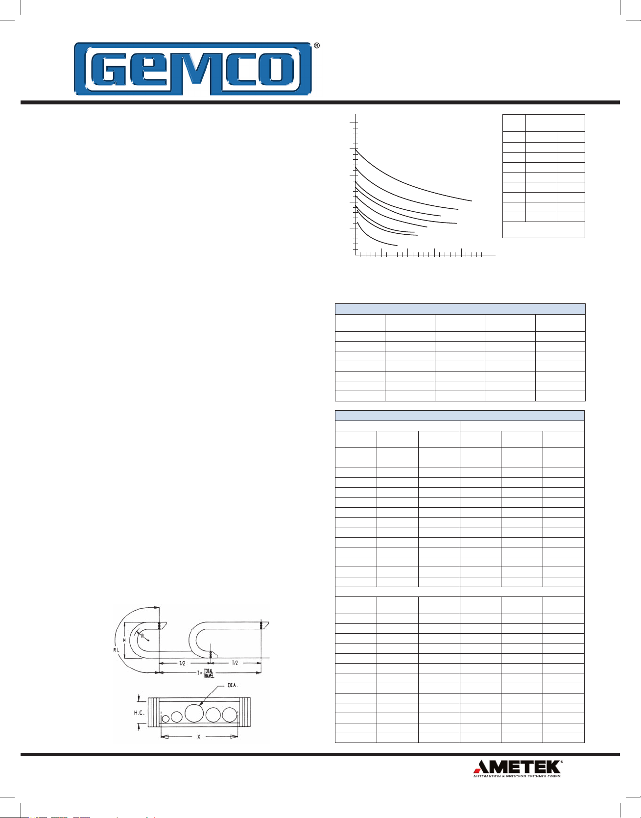
Which CATRAC is right?
1. Determine the outside diameter of the largest cable or
hose to be carried.
2. Determine total machine travel. Unsupported length
of CATRAC® on horizontal applications is total travel
÷ 2 when no supports are used and the stationary
mounting foot is placed at the center line of travel.
3. Determine total weight to be carried per foot.
4. Use the charts to select the proper CATRAC style for
your application. Please note that hose area varies
with type of carriers used.
5. Determine the rolling radius of the CATRAC by:
A) Minimum bend radius of cable or hose
recommended by the manufacturer. If this is not
available, we recommend a minimum of 6 times the
O.D. of the largest cable or hose.
B) Space limitations. The “M” dimension of the
CATRAC must be less than the available space where
track will be installed. The rolling radii shown in the
dimension pages are standard. Special radii and “M”
dimensions are available to suit your application at no
additional cost.
6. Determine CATRAC “X” or inside width. Add the O.D.
of all cables and hoses. Allow a minimum of 0.12”
between each hose or cable and on both sides of the
CATRAC. If vertical separators or hose straps are
used, additional clearance is required.
7. Determine the length of the CATRAC. If the mounting
foot is placed on the center line of travel as shown on
the dimension pages, CATRAC Length = “RL” (radial
length) + 1/2 of total travel (T/2). If the mounting foot is
placed on either side of center line, the distance from
the center line to the mounting foot (Y) must be added.
8. Determine mounting feet requirements and positioning
on the CATRAC assembly.
If you need assistance or have any questions on
special applications, feel free to contact our application
engineers.
50
40
30
20
456
Max. Unsupported Length in Feet
10
0
Lbs/Ft Weight of Cable and/or Hose/Ft Including Liquid in Hoses
The charts below give conservative estimates of cable and hose O.D. and weight
and should be used for quick reference only. Diameters and weights will vary and
should be verifi ed with manufacturer.
Hose Size
I.D x O.D.
1/4 x 18/32 2 300 .18 .03
3/8 x 22/32 2 250 .23 .05
1/2 x 22/32 2 250 .29 .09
3/4 x 1 7/32 2 225 .46 .16
1 x 1 1/2 2 225 .64 .34
1 1/4 x 1 25/32 2 225 .70 .53
1 1/2 x 2 1/32 2 225 .80 .77
No. Cond. Dia. in in/mm Weight lb/ft
2 0.41/10.4 .091/0.14 2 0.53/13.5 .151/0.22
3 0.43/10.9 .112/0.17 3 0.56/14.2 .186/0.26
4 0.49/12.5 .150/0.22 4 0.61/15.5 .221/0.33
5 0.53/13.5 .168/0.25 5 0.62/15.8 .288/0.43
6 0.57/14.5 .195/0.29 6 0.74/18.8 .332/0.49
7 0.61/15.5 .222/0.33 7 0.80/20.3 .362/0.54
8 0.65/16.5 .243/0.36 8 0.85/21.6 .407/0.61
10 0.72/18.3 .306/0.46 10 0.90/22.9 .477/0.71
12 0.74/18.8 .343/0.50 12 0.93/33.6 .529/0.79
16 0.83/21.1 .425/0.63 16 1.08/27.4 .723/1.08
20 0.90/22.9 .512/0.76 20 1.18/30.0 .865/1.29
24 1.02/25.9 .630/0.94 24 1.29/32.8 1.01/1.50
30 1.07/27.2 .745/1.11 30 1.40/35.6 1.25/1.86
36 1.16/29.5 .888/1.32 36 1.51/38.4 1.47/2.19
No. Cond. Dia. in in/mm Weight lb/ft
2 0.61/16.5 .207/0.31 2 0.65/16.5 .243/0.36
3 0.64/16.3 .253/0.38 3 0.70/17.8 .311/0.46
4 0.67/17.0 .297/0.44 4 0.75/19.1 .385/0.57
5 0.73/18.5 .351/0.52 5 0.82/20.8 .461/0.69
6 0.80/20.3 .409/0.61 6 0.88/22.4 .532/0.79
7 0.86/21.8 .472/0.70 7 0.98/24.9 .649/0.97
8 0.92/23.4 .519/0.77 8 1.05/26.7 .717/1.07
10 1.02/25.9 .635/0.95 10 1.13/28.7 .838/1.25
12 1.05/26.7 .706/1.05 12 1.16/29.5 .938/1.40
16 1.16/29.5 .921/1.37 16 1.29/32.8 1.23/1.83
20 1.29/32.8 1.10/1.64 20 1.46/37.1 1.55/2.31
24 1.45/36.8 1.35/2.01 24 1.60/40.6 1.81/2.69
30 1.53/38.9 1.60/2.38
2CP
10 20 30 40 50
16 AWG 14 AWG
12 AWG 10 AWG
304
203
3CP
General Purpose Hose
Braid Max. PSI Hose Weight
Small Cable
kg/m
kg/m
808
606
375
No. Cond. Dia. in in/mm Weight lb/ft
No. Cond. Dia. in in/mm Weight lb/ft
Max. Hose or
Cable Clearance
Style RP/RC, SL WC, AB
203 1.10 1.25
304 1.93 2.00
375 2.67 2.75
456 3.14 3.50
606 4.37 4.50
808 6.00 6.50
2CP 1.18, 1.20 1.25
3CP 1.90 2.00
Consult manufacturer for special
carrier designs.
Lbs/Ft
Liquid Weight
Lbs/Ft
kg/m
kg/m
6380 Brockway Road • Peck, MI 48017 • 800.325.8074 • 810.378.5511 • Fax 810.378.5516 • www.AMETEKAPT.com
3
Page 4

CATRAC
CATRAC
®
Carrier Designs
Carrier Designs
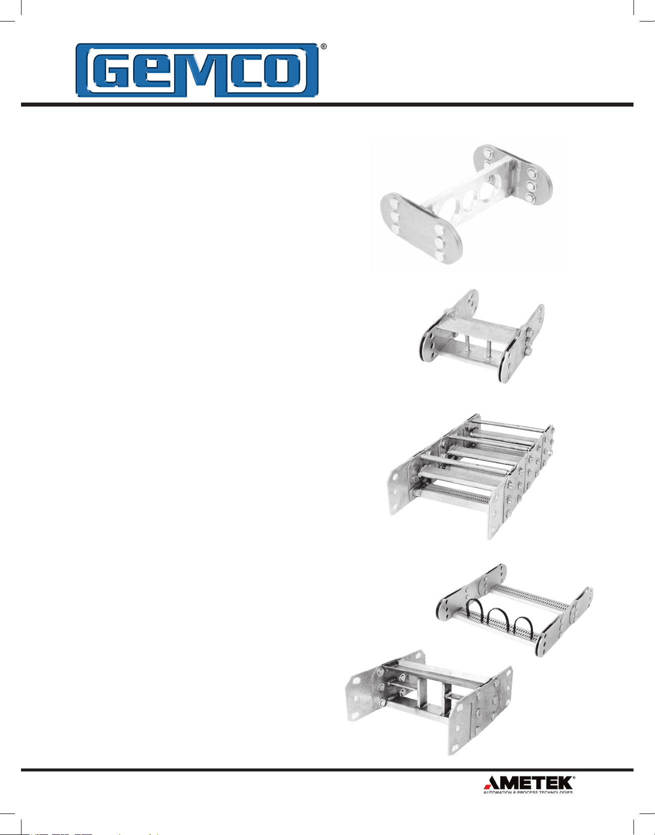
RC Rod Carriers
Available on 2CP, 3CP, 203, 375, 304 style tracks, this
tubing is used to hold the entire CATRAC® together. They
are fastened to links with a self tapping screw that can be
removed from top or bottom rod to make installation of
hose or cable easier.
WC Welded Carriers
The carrier is widely used in very rugged applications. It
can withstand severe hydraulic shock and has no loose
parts which can be lost during installation of the hose
cable. The welded carrier bars alternate position top to
bottom on styles 203, 375 and 304. Styles 456, 606 and
808 use a box beam construction with top and bottom
beams across from each other for added strength.
RP Removable Pipe (Standard)
This assembly provides easy installation of cable and
hose. The pipe can be removed by knocking out a roll pin
and pulling it out the side of the CATRAC.
SL Spring Loaded Removable Pipe
This design provides the quickest way to install or
change cable and hose in the fi eld. Simply compress the
plunger and pull the pipe out. No screws or pins need
to be removed and no side space limitations need to be
considered.
4
6380 Brockway Road • Peck, MI 48017 • 800.325.8074 • 810.378.5511 • Fax 810.378.5516 • www.AMETEKAPT.com
Page 5
CATRAC
CATRAC
®
Carrier Designs
Carrier Designs
AB Split Bar Carriers
1/2” wide aluminum or 3/4” wide wood split bar carriers
can be provided. This carrier is custom machined to your
specifi cations. Note: Holes must be at least 1/8” larger
than cable hose diameter.
VP Vertical Pins
Vertical pins, also referred to as separators or dividers,
can be welded into RP, SL and WC style carriers to
separate cables or hoses to prevent twisting or overlap.
Extra Heavy Duty (Mill-Duty) Construction
For steel mills and other heavy duty service, the double
welded carrier (MD option) is used as well as bolted
construction (BC option). This structure has the ultimate
strength for a carrier. Box beam construction is standard
in the 456, 606, and 808 styles and can withstand severe
hydraulic shock loads.
Optional & Special Carrier Designs
Special perforated carriers can be supplied which provide
openings for hose straps. The hose straps, if used,
should be very loose and used as a hose and cable
separator rather than a tie down.
Many carriers and stiffeners are designed in cooperation
with our customers. We welcome ideas to fi t your specifi c
application needs.
6380 Brockway Road • Peck, MI 48017 • 800.325.8074 • 810.378.5511 • Fax 810.378.5516 • www.AMETEKAPT.com
5
Page 6

2CP and 3CP CATRAC
®
Part Number System
2CP and 3CP CATRAC
Part Number System
®
8060 2CP 2.75 04
CATRAC
CATRAC Side Link
2CP
Ass’y Weight/Ft. 3#
3CP
Ass’y Weight/Ft. 5#
Weight based on 8” carrier.
Radius
“R”*
2CP
3CP
NOTE: Mounting feet must be ordered separately
by the pair. All dimensions are in inches.
2.75 7.50
4.75 11.50
5.63 13.25
*Consult factory for
special radius.
5.13 13.25
6.63 16.25
8.19 19.38
10.90 24.80
15.13 33.25
Overall
Height “M”
Carrier Width*
2CP
3CP
02
04
06
08
*Consult factory for
special widths.
04
06
08
10
12
6
6380 Brockway Road • Peck, MI 48017 • 800.325.8074 • 810.378.5511 • Fax 810.378.5516 • www.AMETEKAPT.com
Page 7
2CP and 3CP CATRAC
2CP and 3CP CATRAC
®
Part Number System
Part Number System
®
WC P Length
P
Pin & Retaining Ring Construction
NOTE: CATRAC Length must
be divisible by pin centers for
that style.
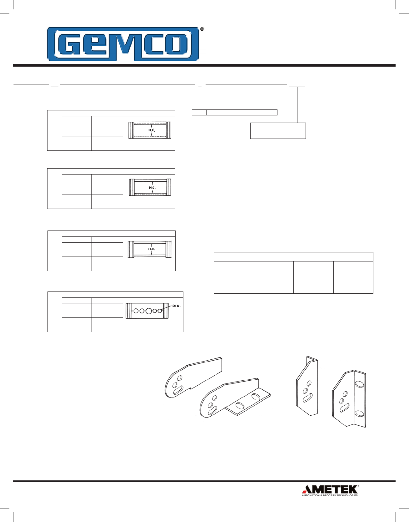
Standard Mounting Feet
CATRAC
Style
2CP PC-0126000-B PC-0127900-B 2 Pair
3CP PC-0128000-B PC-0128100-B 2 Pair
Horiz. Mount
Feet P/N
Normally one (1) pair of mounting feet are used at each end of the
CATRAC. Unless speci ed, anges are mounted inward on standard
CATRAC.
WC
SL
RC
AB
Style HC
Welded Carrier
2CP 1.25
3CP 2.00
Spring Loaded Removable Pipe
Style HC
2CP 1.20
3CP 1.90
Rod Carrier
Style HC
2CP 1.18
3CP 1.90
Split Aluminum Bar Carrier
Style Max. DIA.
2CP 1.25
3CP 2.00
Vert. Mount
Feet P/N
Req’d per
CATRAC
6380 Brockway Road • Peck, MI 48017 • 800.325.8074 • 810.378.5511 • Fax 810.378.5516 • www.AMETEKAPT.com
Vertical Mounting FeetHorizontal Mounting Feet
7
Page 8
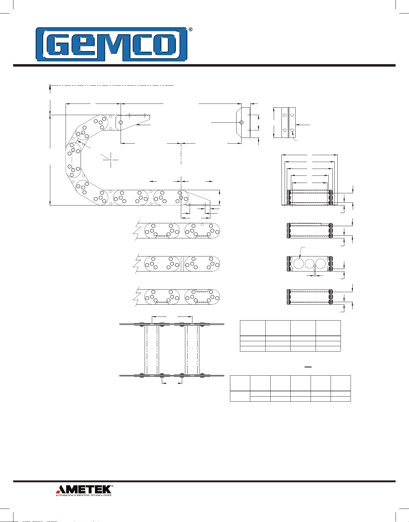
®
CATRAC
®
2CP Dimensions
CATRAC
2CP Dimensions
2.00 CLEARANCE REQUIRED ABOVE LINKS
M
OVERALL
HEIGHT
R
Z
ADIUS
HALF TRAVEL
TOTAL TRAVEL
HORIZONTAL
MTG. FEET
T/2
CENTER LINE
OF TRAVEL
Y** Y**
NOTE:
1) CATRAC LENGTH MUST BE DIVISIBLE
BY PIN CENTERS.
2) ALL STANDARD CARRIER WIDTHS IN 2"
INCREMENTS 2" THRU 8".
3) FOR SPECIAL WIDTHS, CONSULT
FACTORY.
4) ALL PARTS ZINC PLATED UNLESS
OTHERWISE SPECIFIED.
5) MOUNTING SLOTS ARE DESIGNED TO
ALLOW "2CP" REPLACEMENT OF
EXISTING "1A", "2A", & "203" STYLE
CATRAC', STANDARD MTG. FEET.
6.00
3.00
IF THE STATIONARY FOOT IS MOUNTED ON EITHER SIDE OF THE
CENTER LINE OF TRAVEL, THE DISTANCE (Y) BETWEEN CENTER LINE
**
AND STATIONARY FOOT MUST BE ADDED TO CATRAC LENGTH.
T
T/2
HALF TRAVEL
3.00
(SEE BELOW)
2.00
.50
1.50
CATRAC LENGTH = + RL + Y**
STYLE
2CP
REMOVABLE PIPE
* CONSULT FACTORY FOR SPECIAL RADIUS
1.50
3.00
1.50
.75
(RC)
ROD
CARRIER
(SL)
SPRING LOADED
(AB)
SPLIT ALUMINUM
BAR CARRIER
(WC)
WELDED
CARRIER
R
RADIUS *
2.75
4.75
5.63
CARRIER
X
WIDTH
4.00
X
10.00
X + 3.32
Z M
7.00
9.00
C
7.32
VERTICAL
MTG. FEET
.41 X .75 MOUNTING
SLOTS TYPICAL
C
A
B
X
E
dia.
1.25
MAXIMUM
.25
RADIAL
7.50
11.50
13.25
LENGTH
15.00
21.00
24.00
T
2
A
OUTSIDE
MTG.
6.07
X + 2.07
B
OVERALLEINSIDE
5.50
X + 1.50
1.18
.41
1.20
.38
.38
1.25
.38
RL
MTG.
3.54
X - .48
8
6380 Brockway Road • Peck, MI 48017 • 800.325.8074 • 810.378.5511 • Fax 810.378.5516 • www.AMETEKAPT.com
Page 9

®
CATRAC
®
3CP Dimensions
CATRAC
3CP Dimensions
3.00 CLEARANCE REQUIRED ABOVE LINKS
Z
ADIUS
M
OVERALL
HEIGHT
NOTE:
1) CATRAC LENGTH MUST BE DIVISIBLE
BY PIN CENTERS.
2) ALL STANDARD CARRIER WIDTHS IN 2"
INCREMENTS 4" THRU 12".
3) FOR SPECIAL WIDTHS, CONSULT
FACTORY.
4) ALL PARTS ZINC PLATED UNLESS
OTHERWISE SPECIFIED.
5) MOUNTING SLOTS ARE DESIGNED TO
ALLOW "3CP" REPLACEMENT OF
EXISTING "BB", "CC", & "304" STYLE
CATRAC'S, STANDARD MTG. FEET.
R
HORIZONTAL
MTG. FEET
T/2
HALF TRAVEL
Y** Y**
T
TOTAL TRAVEL
CENTER LINE
OF TRAVEL
5.75
8.00
T/2
HALF TRAVEL
(SEE BELOW)
3.00
1.00
3.00
1.75
6.00
3.00
1.50
(RC)
ROD
CARRIER
(SL)
SPRING LOADED
REMOVABLE PIPE
(AB)
SPLIT ALUMINUM
BAR CARRIER
(WC)
WELDED
CARRIER
R
RADIUS *
5.13
6.63
8.19
10.90 17.28 24.80 44.00
15.13 20.87 33.25 56.00
Z M
10.57
13.72
14.83
VERTICAL
MTG. FEET
.41 X .75 MOUNTING
SLOTS TYPICAL
C
A
B
X
E
2.00 dia.
MAXIMUM
13.25
16.25
19.38
.25
RL
RADIAL
LENGTH
24.00
32.00
36.00
1.90
.55
1.90
.50
.38
2.00
.50
* CONSULT FACTORY FOR SPECIAL RADIUS
4.00
IF THE STATIONARY FOOT IS MOUNTED ON EITHER SIDE OF THE
CENTER LINE OF TRAVEL, THE DISTANCE (Y) BETWEEN CENTER LINE
**
AND STATIONARY FOOT MUST BE ADDED TO CATRAC LENGTH.
6380 Brockway Road • Peck, MI 48017 • 800.325.8074 • 810.378.5511 • Fax 810.378.5516 • www.AMETEKAPT.com
CATRAC LENGTH = + RL + Y**
STYLE
CARRIER
3CP
X
WIDTH
4.00
X
C
7.32
X + 3.32
A
OUTSIDE
MTG.
6.21
X + 2.21
T
2
B
OVERALLEINSIDE
5.50
X + 1.50
MTG.
3.38
X - .62
9
Page 10
®
Mill-Duty CATRAC
®
Part Number System
Mill-Duty CATRAC
Part Number System
8060 203 2.75 4
CATRAC
CATRAC Side Link
203
Ass’y Weight/Ft. 5#
304
Ass’y Weight/Ft. 11#
375
Ass’y Weight/Ft. 13#
203
304
375
Radius “R”
2.75 7.50
4.75 11.50
5.63 13.25
8.69 19.38
5.13 13.25
6.63 16.25
8.19 19.38
10.90 24.80
15.13 33.25
5.62 15.00
7.37 18.50
11.12 26.00
14.87 33.50
24.12 52.00
Overall
Height “M”
375
Carrier Width
203
304
4
6
8
10
12
4
6
8
10
12
14
16
18
4
6
8
10
12
14
16
18
456
Ass’y Weight/Ft. 15#
606
Ass’y Weight/Ft. 21#
808
Ass’y Weight/Ft. 30#
Weight based on 8” carrier.
456
606
808
5.88 16.25
7.44 19.38
10.15 24.80
14.38 33.25
21.25 47.00
11.00 28.00
14.81 35.62
20.50 47.00
24.12 54.25
10.50 29.00
12.50 33.00
19.50 47.00
23.12 54.25
456
606
808
4
6
8
10
12
14
16
18
20
6
8
10
12
14
16
18
20
8
10
12
14
16
18
20
22
24
10
6380 Brockway Road • Peck, MI 48017 • 800.325.8074 • 810.378.5511 • Fax 810.378.5516 • www.AMETEKAPT.com
Page 11

®
Mill-Duty CATRAC
®
Part Number System
Mill-Duty CATRAC
Part Number System
WC VP BC Length
Welded Vertical Pins On
Carrier Types RP, SL & WC
VP
X
No Charge
Quantity & Location Per Customer
No Vertical Pins
CATRAC
Style
203 PC-0089000-B PC-0089200-B 2 Pair
304 PC-0091000-B PC-0091200-B 2 Pair
375 PC-0191900-B PC-0192000-B 2 Pair
456 PC-0093000-B PC-0093200-B 2 Pair
606 PC-0095000-B PC-0095200-B 4 Pair
808 PC-0097000-B PC-0097200-B 4 Pair
X
Snap Ring Const.
BC
Bolted Const.
Note: CATRAC Length must
be divisible by pin centers for
that style.
Standard Mounting Feet
Horiz. Mount
Feet P/N
Vert. Mount
Feet P/N
Vertical Mounting Feet
Req’d per
CATRAC
WC
SL
RP
AB
Style HC
Welded Carrier
203 1.25
304 2.00
375 2.75
456 3.50
606 4.50
808 6.50
Spring Loaded Removable Pipe
Style HC
203 1.10
304 1.93
375 2.67
456 3.14
606 4.37
808 6.00
Removable Pipe
Style HC
203 1.10
304 1.93
375 2.67
456 3.14
606 4.37
808 6.00
Split Aluminum Bar Carrier
Style Max. Hole
203 1.25
304 2.00
375 2.75
456 3.50
606 4.50
808 6.50
Normally one (1) pair of mounting
feet are used at each end of the
CATRAC. Unless specified flanges
are mounted inward on standard
CATRAC.
Horizontal Mounting Feet
6380 Brockway Road • Peck, MI 48017 • 800.325.8074 • 810.378.5511 • Fax 810.378.5516 • www.AMETEKAPT.com
11
Page 12

®
CATRAC
®
203 Dimensions
CATRAC
203 Dimensions
2.00 CLEARANCE REQUIRED ABOVE LINKS
M
OVERALL
HEIGHT
R
Z
ADIUS
HALF TRAVEL
TOTAL TRAVEL
HORIZONTAL
MTG. FEET
T/2
CENTER LINE
OF TRAVEL
Y** Y**
NOTE:
1) CATRAC LENGTH MUST BE DIVISIBLE
BY PIN CENTERS.
2) ALL STANDARD CARRIER WIDTHS IN 2"
INCREMENTS 4" THRU 12".
3) FOR MULTIPLE OR SPECIAL WIDTHS,
CONSULT FACTORY.
4) ALL PARTS ZINC PLATED UNLESS
OTHERWISE SPECIFIED.
6.00
3.00
IF THE STATIONARY FOOT IS MOUNTED ON EITHER SIDE OF THE
CENTER LINE OF TRAVEL, THE DISTANCE (Y) BETWEEN CENTER LINE
**
AND STATIONARY FOOT MUST BE ADDED TO CATRAC LENGTH.
T
T/2
HALF TRAVEL
(SEE BELOW)
2.00
.50
3.50
1.50
REMOVABLE PIPE
* CONSULT FACTORY FOR SPECIAL RADIUS
CATRAC LENGTH = + RL + Y**
STYLE
203
PIN
203
BOLTED
1.50
3.00
1.50
.75
(RP)
REMOVABLE
PIPE
(SL)
SPRING LOADED
(AB)
SPLIT ALUMINUM
BAR CARRIER
(WC)
WELDED
CARRIER
R
*
RADIUS
2.75
4.75
5.63
8.69
CARRIER
10.00
14.00
X
WIDTH
4.00
X
X + 3.39
4.00 7.39
X
X + 3.39
7.00
9.00
.38 X .56 MOUNTING
SLOTS TYPICAL
Z M
7.50
11.50
13.25
19.38
C
7.39
A
OUTSIDE
MTG.
6.28
X + 2.28
6.28
X + 2.28
VERTICAL
MTG. FEET
C
A
B
X
E
1.25 dia.
MAXIMUM
.25.38
RL
RADIAL
LENGTH
15.00
21.00
24.00
36.00
T
2
B
OVERALLEINSIDE
5.79
X + 1.79
6.29
X + 2.29
1.10
.38
1.10
.38
.38
1.25
.38
MTG.
3.65
X - .35
3.65
X - .35
12
6380 Brockway Road • Peck, MI 48017 • 800.325.8074 • 810.378.5511 • Fax 810.378.5516 • www.AMETEKAPT.com
Page 13

®
CATRAC
304 Dimensions
3.00 CLEARANCE REQUIRED ABOVE LINKS
M
OVERALL
HEIGHT
R
Z
ADIUS
HALF TRAVEL
TOTAL TRAVEL
HORIZONTAL
MTG. FEET
T/2
CENTER LINE
OF TRAVEL
Y** Y**
NOTE:
1) CATRAC LENGTH MUST BE DIVISIBLE
BY PIN CENTERS.
2) ALL STANDARD CARRIER WIDTHS IN 2"
INCREMENTS 4" THRU 18".
3) FOR MULTIPLE OR SPECIAL WIDTHS
CONSULT FACTORY.
4) ALL PARTS ZINC PLATED UNLESS
OTHERWISE SPECIFIED.
8.00
4.00
IF THE STATIONARY FOOT IS MOUNTED ON EITHER SIDE OF THE
CENTER LINE OF TRAVEL, THE DISTANCE (Y) BETWEEN CENTER LINE
**
AND STATIONARY FOOT MUST BE ADDED TO CATRAC LENGTH.
T
T/2
HALF TRAVEL
5.75
(SEE BELOW)
3.00
1.00
3.00
CATRAC LENGTH = + RL + Y**
STYLE
304
PIN
304
BOLTED
1.75
1.00
1.00
6.00
1.00
1.50
(RP)
REMOVABLE
PIPE
(SL)
SPRING LOADED
REMOVABLE PIPE
(AB)
SPLIT ALUMINUM
BAR CARRIER
(WC)
WELDED
CARRIER
R
RADIUS *
5.13
6.63
8.19
10.90
15.13
*
CONSULT FACTORY FOR SPECIAL RADIUS
Z
10.57 13.25
13.72
14.83
17.28
20.87 33.25 56.00
VERTICAL
MTG. FEET
.41 X .75 MOUNTING
SLOTS TYPICAL
C
A
B
X
E
Ø2.00
MAXIMUM
.25.38
RL
M
16.25
19.38
24.80
RADIAL
LENGTH
24.00
32.00
36.00
44.00
T
2
X
CARRIER
WIDTH
4.00
X
4.00
X
7.88C6.55
X + 3.88
7.88
X + 3.88
A
OUTSIDE
MTG.
X + 2.55
6.55
X + 2.55
B
OVERALL
5.79
X + 1.79
6.29
X + 2.29
.50
.50
.50
.50
E
INSIDE
MTG.
3.38
X - .62
3.38
X - .62
1.93
1.93
2.00
6380 Brockway Road • Peck, MI 48017 • 800.325.8074 • 810.378.5511 • Fax 810.378.5516 • www.AMETEKAPT.com
13
Page 14

CATRAC
®
375 Dimensions
3.75 CLEARANCE REQUIRED ABOVE LINKS
CATRAC
®
456 Dimensions
A
B
C
X
E
4.50
3.00
.75
6.00
M
OVERALL
HEIGHT
R
ADIUS
T/2
HALF TRAVEL
T/2
HALF TRAVEL
T
TOTAL TRAVEL
CENTER LINE
OF TRAVEL
Z
HORIZONTAL
MTG. FEET
VERTICAL
MTG. FEET
1.00
1.50
1.00
1.00
6.00
.41 X .75 MOUNTING
SLOTS TYPICAL
4.50 CLEARANCE REQUIRED ABOVE LINKS
3.50
.50
.50
(WC)
WELDED
CARRIER
(RP)
REMOVABLE
PIPE
3.14
(SL)
SPRING LOADED
REMOVABLE PIPE
3.14
.50
(AB)
SPLIT ALUMINUM
BAR CARRIER
.50
3.50 dia.
MAXIMUM
.25.50
Y** Y**
IF THE STATIONARY FOOT IS MOUNTED ON EITHER SIDE OF THE
CENTER LINE OF TRAVEL, THE DISTANCE (Y) BETWEEN CENTER LINE
AND STATIONARY FOOT MUST BE ADDED TO CATRAC LENGTH.
**
CATRAC LENGTH = + RL + Y**
*
CONSULT FACTORY FOR SPECIAL RADIUS
X + 4.13
X + 4.13
24.00
20.50
Z
6.00
X
CARRIER
WIDTH
STYLE
PIN
456
BOLTED
456
X
4.00
X
4.00
7.44
5.88
12.00
RADIUS *
R
RADIAL
LENGTH
3.42
X - .58
E
INSIDE
MTG.
X - .58
3.42
B
OVERALL
A
OUTSIDE
MTG.
X + 2.75
8.13
X + 2.75
6.75
8.13C6.75
X + 2.03
X + 2.53
6.53
6.03
T
2
19.38
33.25
24.80
60.00
48.00
36.00
30.00
M
RL
NOTE:
1) CATRAC LENGTH MUST BE DIVISIBLE
BY PIN CENTERS.
2) ALL STANDARD CARRIER WIDTHS IN 2"
INCREMENTS 4" THRU 20".
3) FOR MULTIPLE OR SPECIAL WIDTHS,
CONSULT FACTORY.
4) ALL PARTS ZINC PLATED UNLESS
OTHERWISE SPECIFIED.
32.00 47.00 84.00
14.38
21.25
16.00
14.00 16.25
(SEE BELOW)
3.50
10.15
Z
ADIUS
M
OVERALL
HEIGHT
R
HALF TRAVEL
TOTAL TRAVEL
.41 X 1.27 MOUNTING SLOTS
HORIZONTAL
MTG. FEET
T/2
CENTER LINE
Y** Y**
NOTE:
1) CATRAC LENGTH MUST BE DIVISIBLE
BY PIN CENTERS.
2) ALL STANDARD CARRIER WIDTHS IN 2"
INCREMENTS 4" THRU 20".
3) FOR MULTIPLE OR SPECIAL WIDTHS,
CONSULT FACTORY.
4) STANDARD CONSTRUCTION IS WITH
SNAP RINGS OUTSIDE.
5) ALL PARTS ZINC PLATED UNLESS
OTHERWISE SPECIFIED.
IF THE STATIONARY FOOT IS MOUNTED ON EITHER SIDE OF THE
CENTER LINE OF TRAVEL, THE DISTANCE (Y) BETWEEN CENTER LINE
**
AND STATIONARY FOOT MUST BE ADDED TO CATRAC LENGTH.
10.00
5.00
T
OF TRAVEL
®
CATRAC
375 Dimensions
T/2
HALF TRAVEL
(SEE BELOW)
3.75
.75
6.13
3.00
REMOVABLE PIPE
*
CATRAC LENGTH = + RL + Y**
STYLE
375
PIN
375
BOLTED
2.13
6.00
3.00
1.50
(RC)
ROD
CARRIER
(SL)
SPRING LOADED
(AB)
SPLIT ALUMINUM
BAR CARRIER
(WC)
WELDED
CARRIER
R
RADIUS *
5.62
7.37
11.12
14.87
24.12
CONSULT FACTORY FOR SPECIAL RADIUS
X
CARRIER
WIDTH
4.00
X
4.00
X
Z
13.67 15.00
15.18
18.04
23.39
33.11 52.00 90.00
8.11C6.31
X + 4.11
8.11
18.50
26.00
33.50
A
OUTSIDE
MTG.
X + 2.31
6.31
X + 2.31X + 4.11
VERTICAL
MTG. FEET
.41 X .75 MOUNTING
SLOTS
C
A
B
X
E
2.75 dia.
MAXIMUM
M
.25.50
RL
RADIAL
LENGTH
30.00
35.00
45.00
60.00
.54
.50
.50
.50
T
2
B
OVERALL
5.22
X + 1.22
5.88
X + 1.88
E
INSIDE
MTG.
2.32
X - 1.68
2.32
X - 1.68
USABLE
INSIDE
WIDTH
3.78
X - .22
3.78
X - .22
2.67
2.67
2.75
14
6380 Brockway Road • Peck, MI 48017 • 800.325.8074 • 810.378.5511 • Fax 810.378.5516 • www.AMETEKAPT.com
Page 15

®
CATRAC
®
456 Dimensions
CATRAC
456 Dimensions
4.50 CLEARANCE REQUIRED ABOVE LINKS
M
OVERALL
HEIGHT
R
Z
ADIUS
HALF TRAVEL
TOTAL TRAVEL
HORIZONTAL
MTG. FEET
T/2
CENTER LINE
OF TRAVEL
Y** Y**
NOTE:
1) CATRAC LENGTH MUST BE DIVISIBLE
BY PIN CENTERS.
2) ALL STANDARD CARRIER WIDTHS IN 2"
INCREMENTS 4" THRU 20".
3) FOR MULTIPLE OR SPECIAL WIDTHS,
CONSULT FACTORY.
4) ALL PARTS ZINC PLATED UNLESS
OTHERWISE SPECIFIED.
12.00
6.00
IF THE STATIONARY FOOT IS MOUNTED ON EITHER SIDE OF THE
CENTER LINE OF TRAVEL, THE DISTANCE (Y) BETWEEN CENTER LINE
**
AND STATIONARY FOOT MUST BE ADDED TO CATRAC LENGTH.
T
T/2
HALF TRAVEL
(SEE BELOW)
4.50
.75
6.00
3.00
3.50
1.00
1.00
1.00
1.50
(RP)
REMOVABLE
PIPE
(SL)
SPRING LOADED
REMOVABLE PIPE
(AB)
SPLIT ALUMINUM
BAR CARRIER
(WC)
WELDED
CARRIER
R
RADIUS *
5.88
7.44
10.15
14.38
21.25
*
CONSULT FACTORY FOR SPECIAL RADIUS
14.00 16.25
16.00
20.50
24.00
32.00 47.00 84.00
CATRAC LENGTH = + RL + Y**
STYLE
456
PIN
456
BOLTED
X
CARRIER
WIDTH
4.00
X
4.00
X
X + 4.13
X + 4.13
6.00
Z
19.38
24.80
33.25
OUTSIDE
8.13C6.75
8.13
MTG.
X + 2.75
6.75
X + 2.75
VERTICAL
MTG. FEET
.41 X .75 MOUNTING
SLOTS TYPICAL
C
A
B
X
E
3.50 dia.
MAXIMUM
.25.50
RL
M
RADIAL
LENGTH
30.00
36.00
48.00
60.00
T
2
A
B
OVERALL
6.03
X + 2.03
6.53
X + 2.53
.50
.50
.50
.50
E
INSIDE
MTG.
3.42
X - .58
3.42
X - .58
3.14
3.14
3.50
6380 Brockway Road • Peck, MI 48017 • 800.325.8074 • 810.378.5511 • Fax 810.378.5516 • www.AMETEKAPT.com
15
Page 16

®
CATRAC
606 Dimensions
16
6380 Brockway Road • Peck, MI 48017 • 800.325.8074 • 810.378.5511 • Fax 810.378.5516 • www.AMETEKAPT.com
Page 17

®
CATRAC
808 Dimensions
6380 Brockway Road • Peck, MI 48017 • 800.325.8074 • 810.378.5511 • Fax 810.378.5516 • www.AMETEKAPT.com
17
Page 18

Stationary Roller
Part Number System
PD-486 203 5.63 4
Stationary Roller
Part Number System
Stationary
Roller
Support
CATRAC
Style
203
304
375
456
606
808
Radius B Dim.
5.63 11.25
8.69 17.38
5.13 10.25
6.63 13.25
8.19 16.38
10.90 21.80
15.13 30.25
5.62 11.25
7.37 14.75
11.12 22.25
14.87 29.75
24.12 48.25
5.88 11.75
7.44 14.88
10.15 20.30
14.38 28.75
21.25 42.50
11.00 22.00
14.81 29.62
20.50 41.00
24.12 48.25
10.50 21.00
12.50 25.00
19.50 39.00
23.12 46.25
Carrier Width
4
6
8
10
12
14
16
18
20
22
24
Consult factory for
carrier widths and
radii not shown.
PILLOW BLOCK BEARINGS FOR EASY REPAIR
NOTE:
HEAVY DUTY MTG. FEET
USED WHEN B-DIMENSION
IS 23.50 OR OVER
CATRAC® with roller support systems
The roller supports provide a means of
maintaining the maximum unsupported length
while increasing the total travel. There are four
methods of extending the total travel:
1. Utilize a CATRAC with a high side link which
provides a greater unsupported length.
2. Utilize stationary roller supports.
3. Utilize a combination of stationary and
retractable roller supports.
4. Utilize a carriage support system.
OR REPLACEMENT IN FIELD IF DAMAGED
11.00 dia.
3.00
X
203, 304, 456, 606, 808 Styles of CATRAC*
Carrier Width A Dim. C Dim.
4.00 13.52 11.52
x x + 9.52 x + 7.52
Nuts Out x + 10.02 x + 8.02
Note: Approximate dimensions, not for construction unless certified.
All dimensions in inches unless otherwise specified.
*375 Style Consult Factory.
NO ROLLER SUPPORT UL =
T
2
T
T
2
CLEARANCE FOR
.5
6.00
8.00
18.00
20.00
T = TOTAL TRAVEL
UL= MAXIMUM UNSUPPORTED LENGTH
ONE STATIONARY ROLLER SUPPORT UL =
B
0 dia. BOLTS
C
A
T
3
T
T
3
18
6380 Brockway Road • Peck, MI 48017 • 800.325.8074 • 810.378.5511 • Fax 810.378.5516 • www.AMETEKAPT.com
Page 19

Retractable Roller
50
M
OVERALL
CATRAC
HEIGHT
*
A
C
X
B
G
F
E
D
NOTE:
FOR CATRAC SYSTEMS WITH RETRACTABLE ROLLER SUPPORTS,
OVERALL HEIGHT OF SYSTEM WILL BE INCREASED BY 1.38"
UNLESS RETRACTABLE ROLLER SUPPORT BASE IS RECESSED.
*
1.38
1.38
27.75
21.75
5.14
ADJUSTABLE HEIGHT
Retractable Roller
Part Number System
Part Number System
PD-1218 304 5.13 8
Retractable
Roller
Support
CATRAC
Style
304
375
456
606
808
Radius B Dim.
5.13 11.13
6.63 14.13
8.19 17.26
10.90 22.68
15.13 31.13
5.62 12.13
7.37 15.63
11.12 23.13
14.87 30.63
24.12 49.13
5.88 12.63
7.44 15.76
10.15 21.18
14.38 29.63
21.25 43.38
11.00 22.88
14.81 30.50
20.50 41.88
24.12 49.13
10.50 21.88
12.50 25.88
19.50 39.88
23.12 47.13
Carrier Width
8
10
12
14
16
18
20
For radii not shown and
for multiple carrier widths,
consult factory.
Carrier
Width
8.00 34.50 12.50 10.75 20.00 32.00 36.50
x x + 26.50 x + 4.50 x + 2.75 x + 12.00 x + 24.00 x + 28.50
Nuts Out Consult Factory
304, 456, 606, 808 Styles of CATRAC*
A Dim. C Dim. D Dim. E Dim. F Dim. G Dim.
Note: Approximate dimensions, not for construction unless certified.
All dimensions in inches unless otherwise specified.
*375 Style Consult Factory.
T = TOTAL TRAVEL UL = MAXIMUM UNSUPPORTED LENGTH
TWO STATIONARY ROLLER SUPPORT UL =
T
TWO STATIONARY ROLLER SUPPORT UL =
T
T
4
T
4
T
6
T
4
T
6380 Brockway Road • Peck, MI 48017 • 800.325.8074 • 810.378.5511 • Fax 810.378.5516 • www.AMETEKAPT.com
6
T
6
T
6
T
6
19
Page 20

Carriage Support Systems
CATRAC® Carriage
Support System
Carriage support systems are used when cable/hose
loads and travel exceed the limits available with fi xed
roller supports and designed for applications requiring
long travels, high speeds, quick accelerations and
constant cycling. These systems are normally used in
®
CATRAC
Carriage
Support System
conjunction with 304 and 456 CATRAC styles. Special
Mill-Duty carriage support systems are available for
extreme environments. Some of the varieties available
are shown on this page. Call our application engineers
for more information at 800.325.8074.
20
Section AA Section DDSection BB Section CC
6380 Brockway Road • Peck, MI 48017 • 800.325.8074 • 810.378.5511 • Fax 810.378.5516 • www.AMETEKAPT.com
Page 21

CATRAC® Applications
CATRAC® Applications
CATRAC
®
Applications
Primary Metals
Tundish Cars
Ladle Cars
Torch Cut Off Machines
Slab Markers
Mud Gun
Ladle Lance
Pickling Line
Strip Mills
Furnaces
“Dummy” Bar
Continuous Annealing Lines
Construction Machinery
Manlifts
Aerial Lifts
Utility Trucks
Underground Boring
Milling/Drilling Machinery
Drilling Machines
Offshore Drilling Platforms
Rolling Mill Machinery
Coil Processing Equipment
Slitting Line
Roll Grinders
Walking Beam
Machine Tool & Specialty
Equipment
Lathes
Milling Machines
Routers
Shearing
Stamping
Loaders/Extractors
Flame Cutters
Automatic Vehicle Wash
Gantry Crane
Part Shuttles
Press Feeders
High-Pressure Water Washdown
Equipment
Stackers/Reclaimers
X-Ray Gauges
Packaging/Material Handling
Palletizers
Wrappers
Shuttles
Rubber Tired Vehicles
Factory Automation
Automation Storage & Retrieval
System
Other
Pulp/Paper Industry
Lumber Industry
CATRAC Automotive
Applications
Stamping Related
Coil Handling Equipment
Die Transfer Carts
Shuttles
In Die Transfer Equipment
Stacker & Destacker Equipment
Stamping Press Heads
Assembly Plants
Radiator Fluid Filling Lines
Brake Fluid Filling Lines
Body Transfer Lines
Welding Lines
Chassis Assembly Lines
Raw Material
Loading/Unloading Cranes
Stacker/Reclaimer Cranes
Steel Making
Ladle Lance
Ladle Transfer Cars
Tundish Cars
Starter Bar
Torch Cut-Off Machine
Run Out Table
Soaking Pit Transfer Car
Scarfi ng Machine
Hot/Cold Strip Mills
Walking Beam
Reheat Surface
Coil Buggies
X-Ray Machines
Slitter Machines
Back Up Roll Sleds
Pay Off Reel
Coil Upender
Entry/Exit Cars
6380 Brockway Road • Peck, MI 48017 • 800.325.8074 • 810.378.5511 • Fax 810.378.5516 • www.AMETEKAPT.com
21
Page 22

Steel Mill Applications
Steel Mill Applications
Mining - Iron Ore - Coal Limestone
Ore Beneficiation
Preparation
Cleaning
Belt Trippers
Stackers
Reclaimers
Bedding Machines
Trenchers
Shipping - Rail - Water - Raw
Material Storage
Stackers
Reclaimers
Belt Trippers
Car Dumpers
Integrated Steel Making
Plants
Raw Material - Storage &
Preparation
Stackers
Reclaimers
Belt Trippers
Car Dumpers
Trenchers
Sinter Plants
Belt Trippers
Bedding Machine
Trenching Machine
Reclaimer
Coke Oven Batteries
Coke Battery Ovens - Coke
Side
Door Machine
Smoke Suppressor
Quench Cars
Wharf Plows
Blast Furnaces
Taphole Drills
Mud Guns
Burden Distributor Car
Sensing Lances
Steel Making Open Hearth
Charging Machine
Ladle Transfer Cars
Hot Metal (Molten Iron)
Teeming Aisle (Molten Steel)
Slag Pot
Mold Preparation Vacuum & Dust
Machine
Basic Oxygen Furnace (BOF)
Scrap Prep. Cutting Gantry
Water Cooled Doors
Removable Hood Section
Belt Tripper - Flux Handling
Refractory Gunning Machines
Lance Carriage
Horizontal
Preheat
Temperature Data
Ladle Transfer Cars
Hot Metal (Molten Iron)
Teeming Aisle (Molten Steel)
Slag Pot
Argon Lance
Continuous Casting - Slab,
Boom, Billet
Ladle Transfer Car
Tundish
Transfer Car
Heat Shield Car
Pouring Station
Shroud Positioner
Starting Bar
Transfer Car
Heat Shield Car
Pouring Station
Shroud Positioner
Starter Bar
Storage Rack
Cut Off Machine
Torch Machine
Cutoff Torch Traverse
Torch Edge Cutting Machine
Upcut Shear
Slab Sizing Mill - Roll Sleds
Stamping Marking Machine
Disappearing Stop
Piler - Pusher
Slab, Blooming, Billet Mills
- Shapers
Soaking Pit Transfer Cars
Double Manipulator - Rolling Edge
Guides
Roll Sleds
Scarfi ng Machine
Supply
Adjustable Heads
Crop Shear
Marking - Stamping Machine
Coal Preparation - Coke
Storage
Stackers
Reclaimers
Belt Trippers
Trenchers
Coke Battery Ovens - Coal
Side
Lary Charge Cars
Smoke Blow Pipe Cleaners
Charge & Cover Machine
Pushing Machine - Levelers
22
Electric Furnace
Ladle Transfer Cars
Furnace Tilt
Teeming Aisle (Molten Steel)
Cover Turn
Charge Machines
Argon Lance
6380 Brockway Road • Peck, MI 48017 • 800.325.8074 • 810.378.5511 • Fax 810.378.5516 • www.AMETEKAPT.com
Page 23

Steel Mill Applications
Steel Mill Applications
Hot Strip Mills
Primary Rolling
Roll Sleds, Backup and Work Roll
Vertical Scale Breaker
Horizontal Scale Breaker
Roughing Mills
Finishing Mills
Descale Systems
Morgoil Lubrications
Coilers
Mandrel Carriage
Stripper Cars
X-Ray Machines
Finishing - Processing
Transfer Cars
Oil Buggies
Combo Line
Skin Pass Line
Slitters & Shears
Coil Carrier Hook
Walking Beam Coil Transfer
Auxiliaries
Transfer Cars
Work Rolls
Backup Rolls
Bearing Extractor Car
Sheet Mills - Cold Rolling
Continuous Pickling Line
Entry Coil Cars - Buggies
Welders
Tension Wheels - Exit Coil Cars
Mandrel Carriages - Coilers
Belt Wrappers
Oilers
Pay Off Reels
Upender/Downender
Tandem Cold Rolling Mills
Coil Transfer Cars
Entry Horn Car
Quick Work Roll Change Car
Backup Roll Sled
Work Roll Turntable Sled
Belt Wrapper Transfer
Lift & Turn Coil Transfer
Temper Mill - Single Stand - Duo Mill
Coil Prep & Transfer
Entry Coil Car
Quick Work Roll Change Car
Exit Transfer Car
Back Uproll Sleds
Auxiliary Cold Mill Equipment
Dechocking Car - Roll Shop
Lathes & Grinders - Roll Shop
Slitter & Shear Process Lines
Entry & Exit Coil Cars
Recoil Mandrel Carriage
Payoff Reels
Belt Wrapper Transfer
Coil Band & Strapping
Upender/Downender
Continuous Anneal Lines
Exit & Entry Coil Cars
X-Ray Machines
Tension Reel Mandrel Carriages
Coating & Plating
Lines - Tin - Al - Chrome - Zinc
Galvanize
Vertical Spangle Unit
Horizontal Steam Supply
Zinc Hot Metal Pot
Welding Machine
Corrugating Lines
Upender/Downender
Plate Mills
Roll Change Sleds
Morgoil & Lube Systems
X-Ray Gauge
Descale Piping
Side Shear & Edge Gauge
End Gauge
Leveler
Structural Mills - Rail Mills
Rolling Mill Sleds
End Shear
Straightener
Bar and Rod Mills
Roll Sleds
End Shears
Straightener
Coiler Mandrel Carriage
Seamless and Butt Weld Pipe
Mills
End Piercing Machine
Billet Charging Machine
Roll Shops
Grinders
Lathes
Chock Extractors
Roll Transfer Cars
Auxiliary Process Lines
Tension Leveling
Degreasing
Paint Coating
Shear
Shot Blast
Cut to Length
Slitting Line
Continuous Paint Line
Galvanize Line
Edge Trim Line
Grind & Polish
Anneal
Embossing
Side Trim
Chrome - TFS
Tin Line
6380 Brockway Road • Peck, MI 48017 • 800.325.8074 • 810.378.5511 • Fax 810.378.5516 • www.AMETEKAPT.com
23
Page 24

Mill-Duty CATRAC
Mill-Duty CATRAC
®
®
CATRAC® MD for the Primary Metals Industry
This industry readily accepts only those products that
are made exceptionally strong to the point of being
“overbuilt”. If the product doesn’t look like it belongs in
that environment, it doesn’t.
Reliability is the Foremost Requirement
This industry knows no product that they can’t destroy
regularly, our mill-duty CATRACs are designed to be the
most rugged assemblies available.
CATRAC is Stronger
All steel construction fabricated from 80,000 lb. tensile
steel links, assembled with 9/16, 3/4 or 1” hardened
shoulder bolts and locknuts, welded box beam carriers
absorb side thrust loads, can be made to travel and span
the longest distances in the industry.
Cable & Hose Replacement is Easy
The box beam carrier has free space that allows the bad
cable or hose to be easily snaked out. The carrier bars
can have spring loaded retaining rods, allowing the whole
bundle of hoses to be removed and replaced at once.
Available in Any and ALL Sizes
Made to any width or radius with more hose and cable
carrying capacity in a box beam carrier, it can handle 8”
I.D. hose or 12” O.D. cable. We also offer multiple widths
and double deck carrier assemblies.
Retrofit into Present Track Systems
CATRAC is the only known track that can be easily
and regularly made to retrofi t into competitors original
applications. We need only four dimensions to build
CATRAC:
Track Height - “M”
Track Height - “B”
Track Height - “TL”
Hose & Cable Clearance - “HC”
We’ll deliver a stronger system quicker, and at a minimum
cost.
CATRAC is Field Repairable
Because the CATRAC is all steel, it can be straightened
or welded in position. It can be easily unbolted to replace
carriers and links.
CATRAC Value
The competitively priced CATRAC offers more options
for your dollar. Since 1967, CATRAC brand carriers
have been solving customer problems. These years
of experience have supplied us with an opportunity to
provide solutions for numerous applications. This data
allows us to incorporate new and better features into all
CATRAC styles.
24
6380 Brockway Road • Peck, MI 48017 • 800.325.8074 • 810.378.5511 • Fax 810.378.5516 • www.AMETEKAPT.com
Page 25

Chip Covers
CATRAC® Options
Stainless steel chip covers protect hoses against damage
from hot metal chips. The chip covers fi t over the full
length of the CATRAC® assembly, on either the top or
bottom or both sides for maximum protection. The ends
of the chip covers extend six inches beyond the ends
of the CATRAC assembly for attachment. Chip covers
should be fastened on either end to allow them to roll
with the CATRAC. When ordering, specify either outside
or inside covers or both.
Heavy Duty Mounting Feet
Heavy Duty horizontal and vertical mounting feet are
made from 3/16” or 1/4” plate steel and provide the
ultimate in strength at the mounting point. Typical
applications include mill duty equipment and high speed
applications. Custom designs are also available upon
request.
CATRAC
®
Options
Glide Bars and Transfer Bar for Side Mounted
Applications
We offer a wide range of options for side mounted
applications including Nylatron glide bars, round pads
and steel or stainless steel ball casters. We can side
mount virtually any style of CATRAC. Dual radius
CATRACS are also available for rotary applications.
Multiple Carrier Widths
All styles of 3 Pin Center Pivot CATRAC are available
in multiple widths. This type of construction provides
additional strength in wide systems. When width is
a problem double decking of compartments is also
available.
Transfer Balls
Alternated for
Stability
6380 Brockway Road • Peck, MI 48017 • 800.325.8074 • 810.378.5511 • Fax 810.378.5516 • www.AMETEKAPT.com
25
Page 26

®
SnapTrac
®
Nylon Carriers
SnapTrac
Nylon Carriers
Available in a Variety of Sizes
SnapTrac® was developed to offer a light weight, low cost
carrier for protected and controlled movement of cables
and hoses. This corrosion resistant, nonconductive carrier
is made of a longwearing nylon composition. SnapTrac
can be used with electric, air, gas or hydraulic hoses.
A variety of carriers are available offering solutions for
every type of travel. Typical applications for this carrier
include robotics, machine tools, and all types of industrial
equipment. Our application engineers are at your
disposal to study and solve problems related to complex
applications.
Technical Characteristics
Light and secure even at high speeds, SnapTrac
carriers will provide protection for the components
inside the carrier. The carrier is durable against harsh
corrosive environments as found in refi neries and
marine application, chemical fumes, refrigeration fl uids,
lubricating oils and solvent present in a temperature
range from -13°F to 257°F.
Choosing a Carrier
The designer must consider the travel length of the carrier
and the minimum bending radii of the hoses to be carried.
The additional load per foot must also be considered.
Layout of Cable in Carrier
Observe the allowable minimum bending radii of the
cables and hoses to be carried; it is advisable to add an
additional 10%. Cables of small diameter may be grouped
together and tied.
Options
• Enclosed Designs
• Vertical Separator
• Horizontal Separator
• Vertical/Horizontal Separators
• Drilled Frames
26
6380 Brockway Road • Peck, MI 48017 • 800.325.8074 • 810.378.5511 • Fax 810.378.5516 • www.AMETEKAPT.com
Page 27

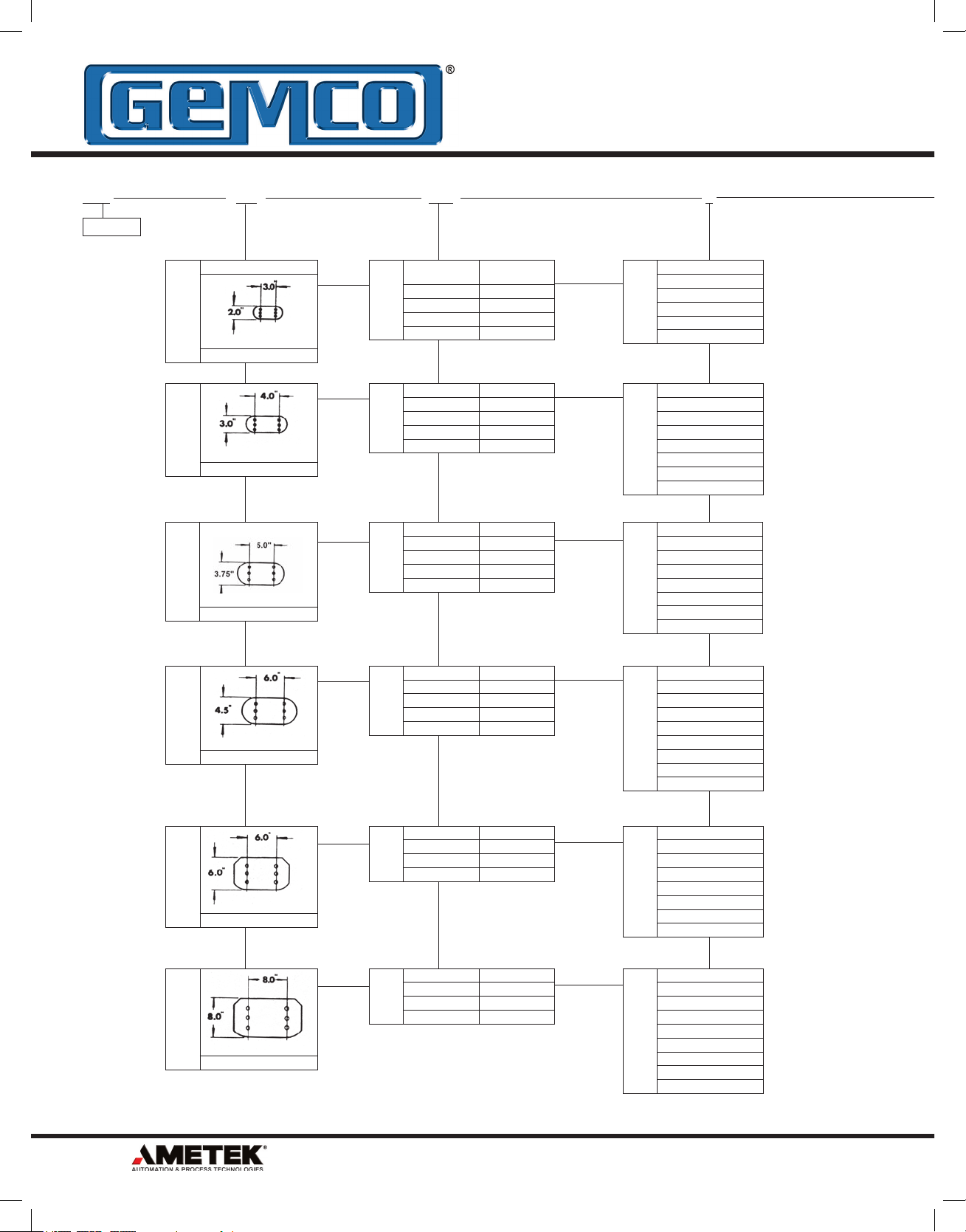
®
SnapTrac
®
Nylon Carriers
SnapTrac
Nylon Carriers
Light SnapTrac
Light series SnapTrac with small to medium sections for
applications where high fi lling weight is not required.
Light SnapTrac
Series
8061SR200
8061SR250
8061
SR30090
8061SR325A
8061SR325
8061SR200 8061SR325A8061SR300908061SR250 8061SR325
A
External
Width mm
18-41 15 12-35 12 18-40
23 22 15 18 40
29-49 23.5 18-38 18.5 33-100
57-120 37 40-103 25.5 50-150
55-118 37 40-103 25.5 50-150
B
External
Height mm
C
Inner
Width mm
D
Inner
Height mm
R
Bending
Radius mm
6380 Brockway Road • Peck, MI 48017 • 800.325.8074 • 810.378.5511 • Fax 810.378.5516 • www.AMETEKAPT.com
27
Page 28

SnapTrac
®
Nylon Carriers
Medium SnapTrac
Small to medium size SnapTrac with yellow connecting pivot
pins offer high capacity in high performace applications.
Available with snap open cover or closed styles.
Medium SnapTrac
Series
8061SR300A
8061SR300
8061SR305A
8061SR305
8061SR355A
8061SR355
8061SR400
8061SR435MI/ME
8061SR445MI/ME
8061SR660A
8061SR770A
8061SR475MI/ME
A
External
Width mm
27-87 23 15-75 18 40-120
30-52 23 14-36 18 40-120
54-74 30 30-50 24 50-150
52-72 30 30-50 20 50-150
74-124 43 45-95 31 75-200
74-124 45 45-95 30 75-200
62-82 35 40-60 25 50-150
60-170 49 40-150 35 60-170
72-384 64 50-362 45 75-300
75-387 55 50-362 37 100-250
80-392 78 45-357 60 150-300
112-412 100.5 74-374 75.5 150-400
B
External
Height mm
C
Inner
Width mm
D
Inner
Height mm
R
Bending
Radius mm
®
SnapTrac
Nylon Carriers
8061SR300A 8061SR3058061SR305A8061SR300
8061SR355A 8061SR435MI/ME8061SR4008061SR355
8061SR445MI/ME 8061SR475MI/ME8061SR770A8061SR660A
28
6380 Brockway Road • Peck, MI 48017 • 800.325.8074 • 810.378.5511 • Fax 810.378.5516 • www.AMETEKAPT.com
Page 29

®
SnapTrac
®
Nylon Carriers
SnapTrac
Nylon Carriers
Heavy SnapTrac
A strong design with triple connecting pivot pins. This design
allows unsupported length up to 6.5 m and extends the
service life of the SnapTrac and cables.
Heavy SnapTrac
Series
8061SR308SI/SE
8061SR309SI/SE
8061SR310T
A
External
Width mm
82-394 75 38-350 57 150-400
120-420 100 64-364 75.5 200-500
260-660 150 200-600 112 200-750
B
External
Height mm
C
Inner
Width mm
D
Inner
Height mm
R
Bending
Radius mm
Protection SnapTrac
A completely enclosed design prevents contact between
cables, chips or dust. Each link has a quickly removable
cover for easy installation of the cables and hoses.
8061SR310T8061SR309SI/SE8061SR308SI/SE
Protection SnapTrac
Series
8061SR435PI/PE
8061SR660
8061SR445PI/PE
8061SR770
8061SR309C
8061SR475PI/PE
8061SR435PI/PE 8061SR445PI/PE8061SR660
A
External
Width mm
60-170 49 40-150 35 75-200
79-179 55 50-150 36 100-250
72-384 64 50-362 45 100-300
120-285 78 85-250 51 150-300
256-456 100 200-400 72 200-500
112-412 100.5 74-374 75.5 180-400
B
External
Height mm
C
Inner
Width mm
D
Inner
Height mm
R
Bending
Radius mm
8061SR660
8061SR770 8061SR475PI/PE8061SR309C
8061SR770
6380 Brockway Road • Peck, MI 48017 • 800.325.8074 • 810.378.5511 • Fax 810.378.5516 • www.AMETEKAPT.com
29
Page 30

®
SnapTrac
®
Nylon Carriers
SnapTrac
Nylon Carriers
Sliding SnapTrac
Sliding SnapTrac is made to be used where travel distance
is long. The links are equipped with skids, allowing the trac
to slide on itself. It is made of special polymers to reduce
friction and wear.
Sliding SnapTrac
Series
8061SR326SI/SE 106-418 59 61-373 37 107-300
8061SR328SI/SE 119-431 79 61-373 57 150-400
8061SR319B 164-464 107 100-400 70 200-500
8061SR200 8061SR300908061SR250
A
External
Width mm
B
External
Height mm
C
Inner
Width mm
D
Inner
Height mm
R
Bending
Radius mm
Robot SnapTrac
SnapTrac offers an innovative solution for circular
applications like welding and painting robots by allowing
rotation of over 360°. Available in 9 different models, each
link has an opening cross piece to allow easy installation of
cables and hoses.
Robot SnapTrac
Series
8061SR495 69 45 45 35 100
8061SR500 93 43 65 30 100-150
8061SR510TN 132 55 88 46 125
8061SR515TN 132 55 88 46 175
8061SR545 123 62 100 46 100
8061SR599 272 85 210 59 220
8061SR250
A
External
Width mm
B
External
Height mm
C
Inner
Width mm
D
Inner
Height mm
R
Bending
Radius mm
8061SR325A8061SR30090
8061SR200
8061SR200
30
6380 Brockway Road • Peck, MI 48017 • 800.325.8074 • 810.378.5511 • Fax 810.378.5516 • www.AMETEKAPT.com
Page 31

®
CATRAC
®
Development Sheet
CATRAC
Development Sheet
Please fi ll in completely and accurately and fax to the CATRAC Sales Department @ (810) 378-5516.
Customer Information
Contact Name Fax
Company Email
Phone Date
Machine / Environment Specifications
Machine Type or Name
Machine Total Travel Distance
Direction / Orientation of Travel
Fixed End Mounting Location
Mounting Bracket Position
Operating Speed (ft/sec)
Acceleration (ft/sec)
Environmental Data
Operating Temperature
Dimensional Limitations OAW = ___________ OAL = ___________ OAH = ___________ (Allow an additional 2 in. for operating clearance in OAH)
❑ Horizontal ❑ Vertical ❑ Side Running ❑ Other If other, please provide sketch.
❑ Center (Of total machine travel) ❑ Off Center (Distance from center_________________)
❑ Inward ❑ Outward ❑ Both ❑ Other
❑ ≤ 5 ft/sec ❑ ≤ 10 ft/sec ❑ ≤ 15 ft/sec ❑ ≥ 15 ft/sec
❑ ≤ 5 ft/sec² ❑ ≤ 10 ft/sec² ❑ ≤ 15 ft/sec² ❑ ≥ 15 ft/sec²
❑ Indoor ❑ Outdoor ❑ Wet* ❑ Dry ❑ Corrosive ❑ Abrasive ❑ Humidity* ❑ Chemical* ❑ Chips* ❑ Hot Metal ❑ Fluid Exposure*
*Please explain type or level________________________________________________________________________________
❑ ≤ 40F (5C) ❑ ≤ 150F (66C) ❑ ≤ 250F (121C)
Carrier Contents
Critical information. Please include MFG cut sheets when possible.
Note: If a bend radius is not provided, the customer agrees to using 8 to 10 times the cable or hose diameter as a factor.
Cable / Hose
Quantity
Outside
Diameter
Weight Per Foot
(Fluid fi lled on hoses)
Min. Bend Radius
(MFG Specifi cations)
6380 Brockway Road • Peck, MI 48017 • 800.325.8074 • 810.378.5511 • Fax 810.378.5516 • www.AMETEKAPT.com
31
Page 32

Other Products
Copyright 2010 by AMETEK AUTOMATION & PROCESS TECHNOLOGIES. All Rights Reserved. Made in the USA.
1080 N. Crooks Road, Clawson, MI 48017-1097
Phone: 248.435.0700 Toll Free: 800.635.0289
Fax: 248.435.8120 www.ametekapt.com
8060.C5R
3/10.Z88
1M
 Loading...