

Page 1

MX15 Series
AC and DC Power Source
User Manual
Revision M
Feb 2015
Copyright 2006 - 2015
AMETEK Programmable Power
All rights reserved.
P/N 7005-960
Page 2

User Manual – Rev M California Instruments
User's Manual
AC Power Source
Models:
MX15-1
MX15-1P
MX15-1Pi
MX30/2-1
MX45/3-1
MX30/2-1Pi (-MB)
MX45/3-1Pi (-MB)
Copyright 2006 - 2015, AMETEK Programmable Power.
MX15 2
Page 3

User Manual – Rev M California Instruments
About AMETEK
AMETEK Programmable Power, Inc., a Division of AMETEK, Inc., is a global leader in the design and
manufacture of precision, programmable power supplies for R&D, test and measurement, process
control, power bus simulation and power conditioning applications across diverse industrial segments.
From bench top supplies to rack-mounted industrial power subsystems, AMETEK Programmable Power
is the proud manufacturer of Elgar, Sorensen, California Instruments and Power Ten brand power
supplies.
AMETEK, Inc. is a leading global manufacturer of electronic instruments and electromechanical devices
with annualized sales of $2.5 billion. The Company has over 11,000 colleagues working at more than 80
manufacturing facilities and more than 80 sales and service centers in the United States and around the
world.
Trademarks
AMETEK is a registered trademark of AMETEK, Inc. California Instruments is a trademark owned by
AMETEK, Inc. Other trademarks, registered trademarks, and product names are the property of their
respective owners and are used herein for identification purposes only.
Notice of Copyright
MX Series User Manual
© 2003-2010 AMETEK Programmable Power, Inc. All rights reserved.
Exclusion for Documentation
UNLESS SPECIFICALLY AGREED TO IN WRITING, AMETEK PROGRAMMABLE POWER, INC. (“AMETEK”):
(a) MAKES NO WARRANTY AS TO THE ACCURACY, SUFFICIENCY OR SUITABILITY OF ANY TECHNICAL
OR OTHER INFORMATION PROVIDED IN ITS MANUALS OR OTHER DOCUMENTATION.
(b) ASSUMES NO RESPONSIBILITY OR LIABILITY FOR LOSSES, DAMAGES, COSTS OR EXPENSES,
WHETHER SPECIAL, DIRECT, INDIRECT, CONSEQUENTIAL OR INCIDENTAL, WHICH MIGHT ARISE
OUT OF THE USE OF SUCH INFORMATION. THE USE OF ANY SUCH INFORMATION WILL BE
ENTIRELY AT THE USER’S RISK, AND
(c) REMINDS YOU THAT IF THIS MANUAL IS IN ANY LANGUAGE OTHER THAN ENGLISH, ALTHOUGH
STEPS HAVE BEEN TAKEN TO MAINTAIN THE ACCURACY OF THE TRANSLATION, THE ACCURACY
CANNOT BE GUARANTEED. APPROVED AMETEK CONTENT IS CONTAINED WITH THE ENGLISH
LANGUAGE VERSION, WHICH IS POSTED AT WWW.PROGRAMMABLEPOWER.COM.
Date and Revision
February 2015 Revision M
Part Number
7005-960
Contact Information
Telephone: 800 733 5427 (toll free in North America)
858 450 0085 (direct)
Fax: 858 458 0267
Email: sales@programmablepower.com
service@programmablepower.com
Web: www.programmablepower.com
MX15 3
Page 4
User Manual – Rev M California Instruments
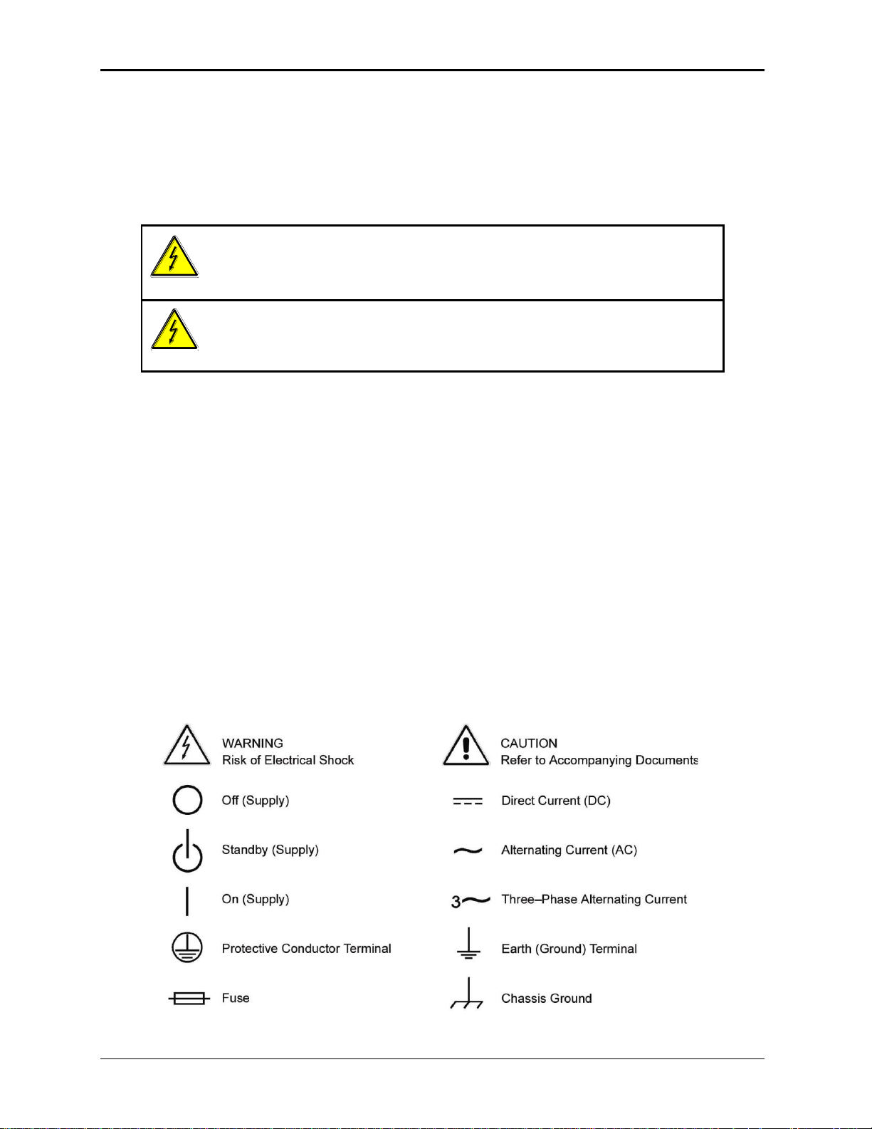
WARNING
Hazardous voltages may be present when covers are removed. Qualified
personnel must use extreme caution when servicing this equipment.
Circuit boards, test points, and output voltages also may be floating above
(below) chassis ground.
WARNING
The equipment used contains ESD sensitive parts. When installing
equipment, follow ESD Safety Procedures. Electrostatic discharges might
cause damage to the equipment.
Important Safety Instructions
Before applying power to the system, verify that your product is configured properly for your particular
application.
Only qualified personnel who deal with attendant hazards in power supplies, are allowed to perform
installation and servicing.
Ensure that the AC power line ground is connected properly to the Power Rack input connector or chassis.
Similarly, other power ground lines including those to application and maintenance equipment must be
grounded properly for both personnel and equipment safety.
Always ensure that facility AC input power is de-energized prior to connecting or disconnecting any cable.
In normal operation, the operator does not have access to hazardous voltages within the chassis. However,
depending on the user’s application configuration, HIGH VOLTAGES HAZARDOUS TO HUMAN SAFETY
may be normally generated on the output terminals. The customer/user must ensure that the output power
lines are labeled properly as to the safety hazards and that any inadvertent contact with hazardous voltages
is eliminated.
Guard against risks of electrical shock during open cover checks by not touching any portion of the
electrical circuits. Even when power is off, capacitors may retain an electrical charge. Use safety glasses
during open cover checks to avoid personal injury by any sudden component failure.
Neither AMETEK Programmable Power Inc., San Diego, California, USA, nor any of the subsidiary sales
organizations can accept any responsibility for personnel, material or inconsequential injury, loss or
damage that results from improper use of the equipment and accessories.
SAFETY SYMBOLS
MX15 4
Page 5

User Manual – Rev M California Instruments
Product Family: MX Series AC Power Source
Warranty Period: 1 Year
WARRANTY TERMS
AMETEK Programmable Power, Inc. (“AMETEK”), provides this written warranty covering the Product
stated above, and if the Buyer discovers and notifies AMETEK in writing of any defect in material or
workmanship within the applicable warranty period stated above, then AMETEK may, at its option: repair
or replace the Product; or issue a credit note for the defective Product; or provide the Buyer with
replacement parts for the Product.
The Buyer will, at its expense, return the defective Product or parts thereof to AMETEK in accordance
with the return procedure specified below. AMETEK will, at its expense, deliver the repaired or replaced
Product or parts to the Buyer. Any warranty of AMETEK will not apply if the Buyer is in default under the
Purchase Order Agreement or where the Product or any part thereof:
is damaged by misuse, accident, negligence or failure to maintain the same as specified or
required by AMETEK;
is damaged by modifications, alterations or attachments thereto which are not authorized
by AMETEK;
is installed or operated contrary to the instructions of AMETEK;
is opened, modified or disassembled in any way without AMETEK’s consent; or
is used in combination with items, articles or materials not authorized by AMETEK.
The Buyer may not assert any claim that the Products are not in conformity with any warranty until the
Buyer has made all payments to AMETEK provided for in the Purchase Order Agreement.
PRODUCT RETURN PROCEDURE
Request a Return Material Authorization (RMA) number from the repair facility (must be done in the
country in which it was purchased):
In the USA, contact the AMETEK Repair Department prior to the return of the product to
AMETEK for repair:
Telephone: 800-733-5427, ext. 2295 or ext. 2463 (toll free North America)
858-450-0085, ext. 2295 or ext. 2463 (direct)
Outside the United States, contact the nearest Authorized Service Center (ASC). A full
listing can be found either through your local distributor or our website,
www.programmablepower.com, by clicking Support and going to the Service Centers tab.
When requesting an RMA, have the following information ready:
Model number
Serial number
Description of the problem
NOTE: Unauthorized returns will not be accepted and will be returned at the shipper’s expense.
NOTE: A returned product found upon inspection by AMETEK, to be in specification is subject to an
evaluation fee and applicable freight charges.
MX15 5
Page 6

User Manual – Rev M California Instruments
Table of Contents
1 Introduction ................................................................................................................................... 10
1.1 General Description ........................................................................................................................ 10
1.2 Manual organization and format ...................................................................................................... 10
2 Specifications ................................................................................................................................ 11
2.1 Electrical ......................................................................................................................................... 11
2.2 Mechanical ...................................................................................................................................... 19
2.3 Environmental ................................................................................................................................. 20
2.4 Regulatory ....................................................................................................................................... 20
2.5 Front Panel Controls ....................................................................................................................... 20
2.6 Special Features and Options ......................................................................................................... 21
2.7 Supplemental Specifications ........................................................................................................... 29
3 Unpacking and Installation ............................................................................................................ 34
3.1 Unpacking ....................................................................................................................................... 34
3.2 Power Requirements ....................................................................................................................... 34
3.3 Mechanical Installation .................................................................................................................... 35
3.4 AC Input Connections and Wiring ................................................................................................... 35
3.5 AC On/Off Circuit Breaker on MX Series front panel. ..................................................................... 39
3.6 Output Connections ........................................................................................................................ 41
3.7 Connectors - Rear Panel ................................................................................................................. 49
3.8 Multiple Cabinet System Configurations (incl. –MB) ....................................................................... 56
3.9 Multiple Cabinet Power Up/Down Procedures ................................................................................ 57
3.10 Clock and Lock Configurations ....................................................................................................... 58
3.11 Basic Initial Functional Test ............................................................................................................ 61
3.12 Remote Inhibit / Remote Shutdown ................................................................................................ 63
3.13 Junction Box Accessory .................................................................................................................. 64
3.14 Output Filter Box Accessory ............................................................................................................ 65
4 Front Panel Operation .................................................................................................................. 66
4.1 Tour of the Front Panel ................................................................................................................... 66
4.2 Menu Structure ................................................................................................................................ 71
4.3 Output Programming ....................................................................................................................... 96
4.4 Waveform Management [1Pi Controller only] ................................................................................. 98
4.5 Standard Measurements ............................................................................................................... 102
4.6 Advanced Measurements [1Pi Controller only] ............................................................................. 104
4.7 Transient Programming ................................................................................................................. 105
5 Principle of Operation ................................................................................................................. 111
5.1 General ......................................................................................................................................... 111
5.2 Overall Description ........................................................................................................................ 111
5.3 Controller Assembly ...................................................................................................................... 113
5.4 System Interface Board ................................................................................................................. 116
5.5 Current / Voltage Sensor Board .................................................................................................... 116
5.6 Low Voltage Power Supply ........................................................................................................... 116
5.7 Power Module ............................................................................................................................... 117
6 Calibration ................................................................................................................................... 122
6.1 Recommended Calibration Equipment ......................................................................................... 122
6.2 Front Panel Calibration Screens ................................................................................................... 123
6.3 Routine Measurement Calibration ................................................................................................ . 124
6.4 Routine Output Calibration ............................................................................................................ 126
6.5 Non-Routine Calibration ................................................................................................................ 127
7 Service ........................................................................................................................................ 130
7.1 Cleaning ........................................................................................................................................ 130
MX15 6
Page 7

User Manual – Rev M California Instruments
7.2 General .......................................................................................................................................... 130
7.3 Basic operation .............................................................................................................................. 130
7.4 Advanced Troubleshooting. ........................................................................................................... 132
7.5 Factory Assistance ........................................................................................................................ 134
7.6 Fuses ............................................................................................................................................. 135
7.7 Firmware Updates ......................................................................................................................... 135
8 Top Assembly Replaceable Parts ............................................................................................... 138
9 Options ........................................................................................................................................ 141
9.1 Introduction .................................................................................................................................... 141
9.2 Option -HV: Additional AC Voltage Range .................................................................................... 141
9.3 Option –160: RTCA/DO-160 Tests ................................................................................................ 142
9.4 Option –704: MilStd704 Tests ....................................................................................................... 156
9.5 Option –ABD: Airbus ABD0100.1.8 Test ....................................................................................... 169
9.6 Option –787: Boeing B787-0147 Test .......................................................................................... 169
9.7 Option –WHM: Watt Hour Measurement ....................................................................................... 170
9.8 Option –411: IEC 61000-4-11 Voltage Dips and Interruptions ...................................................... 171
9.9 Option –413: IEC 61000-4-13 Interharmonics Test ....................................................................... 172
9.10 Option–SNK: Current Sink ............................................................................................................. 174
10 . Error Messages ......................................................................................................................... 177
Index .................................................................................................................................................. 182
MX15 7
Page 8

User Manual – Rev M California Instruments
List of Figures
Figure 2-1: MX15-1 Voltage / Current Rating Chart for 150/300 V AC Ranges – Max Rating. ................................................. 14
Figure 2-2: Voltage / Current Rating Chart for 150/300 V AC Ranges – Derated. ................................................................... 14
Figure 2-3: MX15-1 Voltage / Current Rating Chart for 200/400 V DC Ranges – Max. Rating ................................................ 15
Figure 2-4: Voltage / Current Rating Chart for 200/400 V DC Ranges – Derated .................................................................... 16
Figure 2-5: MX15-1 Voltage / Current Rating Chart, -HV Option – Max. Rating. ..................................................................... 24
Figure 2-6: Voltage / Current Rating Chart, -HV Option – Derated. ......................................................................................... 24
Figure 2-7: -HF Option Voltage Frequency Rating 300V range ............................................................................................... 26
Figure 2-8: -HF Option Voltage Frequency Rating 150V range ............................................................................................... 26
Figure 2-9: MX output filter option schematic .......................................................................................................................... 31
Figure 2-10: MX45 Output Noise 10 KHz – 1 MHz .................................................................................................................. 32
Figure 2-11: MX45 Output Noise 10 KHz - 1 MHz with optional Filter ..................................................................................... 33
Figure 3-1: The MX15 Power Source ...................................................................................................................................... 34
Figure 3-2: Location of AC Input Fuse Block and Chassis Ground Connection - Rear View, Access Panel Removed ........... 36
Figure 3-3: MX Series AC Input Connection Diagram (Rear view) .......................................................................................... 38
Figure 3-4: Rear Panel ........................................................................................................................................................... 40
Figure 3-5: External sense cable shield connection to chassis ground ................................................................................... 41
Figure 3-6: MX15-1 Output Wiring (Rear view) ....................................................................................................................... 43
Figure 3-7: MX30/2 or MX30/2-MB Output Wiring (Rear view) ................................................................................................ 44
Figure 3-8: Two MX's in Clock and Lock mode Output Wiring (Rear view) ............................................................................. 45
Figure 3-9: MX45/3 or MX45/3-MB Output Wiring (Rear view) ................................................................................................ 46
Figure 3-10: Three MX's in Clock and Lock mode - Output Wiring (Rear view) ....................................................................... 47
Figure 3-11: Ship kit Terminal Block dimensions .................................................................................................................... 48
Figure 3-12: RS232C Cable for PC Connection wiring diagram – MX without USB. ............................................................... 53
Figure 3-13: USB Connector pin orientation. .......................................................................................................................... 54
Figure 3-14: Multi-Cabinet DIP Switch Location and Setting ................................................................................................... 56
Figure 3-15: Functional Test Setup. ........................................................................................................................................ 62
Figure 3-16: 7003-416-1 Output Junction Box ........................................................................................................................ 64
Figure 3-17: 7003-424-1 Output noise filter box. ..................................................................................................................... 65
Figure 4-1: Shuttle Knob ......................................................................................................................................................... 68
Figure 4-2: FUNCTION Keypad ............................................................................................................................................. 69
Figure 4-3: Measurement Screen ........................................................................................................................................... 70
Figure 4-4: PROGRAM Menus ............................................................................................................................................... 76
Figure 4-5: CONTROL Menus ................................................................................................................................................ 78
Figure 4-6: MEASUREMENT Screen ..................................................................................................................................... 81
Figure 4-7: Selecting a Waveform .......................................................................................................................................... 98
Figure 4-8: Custom Waveform Creation with GUI Program .................................................................................................... 99
Figure 4-9: Waveform Crest Factor Affects Max. rms Voltage .............................................................................................. 100
Figure 4-10: Pulse Transients ............................................................................................................................................... 106
Figure 4-11: List Transients ................................................................................................ .................................................. 107
Figure 4-12: Sample Transient Output Sequence ................................................................................................................. 108
Figure 4-13: Switching Waveforms in a Transient List .......................................................................................................... 109
Figure 4-14: TRANSIENT Menu ........................................................................................................................................... 110
Figure 5-1: MX Series Functional Block Diagram.................................................................................................................. 111
Figure 5-2: MX Series Detailed Block Diagram ..................................................................................................................... 114
Figure 5-3: Power Module Detailed Block Diagram ............................................................................................................... 115
Figure 5-4: Power Module Layout ......................................................................................................................................... 117
Figure 5-5: Amplifier Board Layout ....................................................................................................................................... 119
Figure 6-1: Calibration Setup MX45-1 (Rear view) ................................................................................................................ 123
Figure 9-1: Application Menu ................................................................................................................................................ 143
Figure 9-2: DO160 Main Menus ............................................................................................................................................ 144
Figure 9-3: Normal state screens.......................................................................................................................................... 144
Figure 9-4: Voltage Modulation - Frequency characteristics ................................................................................................. 147
Figure 9-5: Frequency Modulation ................................................................................................ ................................ ........ 148
Figure 9-6: Power Interrupt ................................................................................................................................................... 149
Figure 9-7: Power Interrupt for Group2/A(NF) and Group3/A(WF) ........................................................................................ 150
Figure 9-8: Emergency Screens ........................................................................................................................................... 152
Figure 9-9: Abnormal Screen ................................................................................................................................................ 153
Figure 9-10: Applications Menu ............................................................................................................................................ 158
Figure 9-11: MIL704 Menu .................................................................................................................................................... 158
Figure 9-12: Steady State Menu ........................................................................................................................................... 159
Figure 9-13: Emergency Menu ............................................................................................................................................. 162
Figure 9-14: Abnormal Screens ............................................................................................................................................ 163
Figure 9-15: MIL704 DC Menu.............................................................................................................................................. 165
Figure 9-16: Steady State DC .............................................................................................................................................. 165
Figure 9-17: Transient Menu ................................................................................................................................................ 166
Figure 9-18: Abnormal Test Screen ...................................................................................................................................... 167
Figure 9-19: Emergency Test ............................................................................................................................................... 168
MX15 8
Page 9

User Manual – Rev M California Instruments
Figure 9-20: Watt-Hour Meter Screen ...................................................................................................................................170
Figure 9-21: WH-Meter Screen with Function Active .............................................................................................................170
Figure 9-22: APPLICATION SCREEN ..................................................................................................................................173
Figure 9-23: INTERHARMONICS SCREENS .......................................................................................................................173
Figure 9-24: REGENERATE CONTROL screen ...................................................................................................................175
List of Tables
Table 3-1: Suggested Input Wiring Sizes for each MX Cabinet * ............................................................................................ 39
Table 3-2: Suggested Output Wiring Sizes * .......................................................................................................................... 42
Table 3-3: System Interface Connectors ................................................................................................................................ 50
Table 3-4: Analog Interface Connector ................................................................................................................................... 50
Table 3-5: BNC Connectors ................................................................................................................................................... 51
Table 3-6: External Sense Connector ..................................................................................................................................... 51
Table 3-7: RS232 Connector pin out – MX with RS232 and USB. .......................................................................................... 52
Table 3-8: RS232C Connector pin out – MX with RS232 but no USB .................................................................................... 52
Table 3-9: USB Connector pin out. ......................................................................................................................................... 54
Table 3-10: RJ45 LAN Connector pin out. .............................................................................................................................. 55
Table 3-11: Clock and Lock Configuration settings ................................................................................................................ 58
Table 3-12: Clock and Lock Initialization settings ................................................................................................ ................... 59
Table 4-1: Menu Tree ............................................................................................................................................................. 75
Table 4-2: Sample Transient List ..........................................................................................................................................108
Table 6-1: Calibration Load Values .......................................................................................................................................124
Table 6-2: Measurement Calibration Table............................................................................................................................125
Table 6-3: Output Calibration Table – MX15 Series ..............................................................................................................126
Table 6-4: Programmable Z adjustment pots ........................................................................................................................129
Table 6-5: Formulas to calculate R and L ..............................................................................................................................129
Table 7-1: Basic Symptoms ..................................................................................................................................................130
Table 7-2: MX Fuse Ratings ..................................................................................................................................................135
Table 7-3: Flash Down load Messages .................................................................................................................................137
Table 8-1: Replaceable Parts ................................................................................................................................................139
Table 8-2: Fuses ................................................................................................................................................................ ...140
Table 9-1: Normal Voltage and Frequency minimum ............................................................................................................145
Table 9-2: Normal Voltage and Frequency Maximum ............................................................................................................145
Table 9-3: Airbus mode voltage modulation. .........................................................................................................................146
Table 9-4: Normal VoltageSurge Sequence ..........................................................................................................................150
Table 9-5: Normal Frequency Transient Sequence ...............................................................................................................151
Table 9-6: Normal Frequency Variation Sequence ................................................................................................................151
Table 9-7: Emergency Voltage and Frequency Minimum ......................................................................................................152
Table 9-8: Emergency Voltage and Frequency Maximum .....................................................................................................152
Table 9-9: Abnormal Voltage Minimum .................................................................................................................................153
Table 9-10: Abnormal Voltage Maximum ..............................................................................................................................153
Table 9-11: Abnormal Frequency Transient ..........................................................................................................................155
Table 9-12: Steady state voltage ...........................................................................................................................................159
Table 9-13: Steady state frequency .......................................................................................................................................160
Table 9-14: Frequency Modulation ........................................................................................................................................160
Table 9-15: Abnormal Over Frequency .................................................................................................................................164
Table 9-16: Abnormal Under Frequency ...............................................................................................................................164
Table 10-1: Error Messages ..................................................................................................................................................181
MX15 9
Page 10

User Manual – Rev M California Instruments
1 Introduction
This instruction manual contains information on the installation, operation, calibration and
maintenance of all power systems that use the MX15 Series power sources with the
programmable controller.
1.1 General Description
The MX15 Series AC and DC power source systems are high efficiency, floor standing AC and
DC power sources that provide a precise output with low distortion. Available voltage ranges are
150 Vac, 300 Vac and 400 Vac in AC mode and 200 Vdc and 400 Vdc in DC mode.
Models with a -1 designation provide full front panel operation but do not include certain features
such as arbitrary waveform generation unless added as an option at the time of order. Models
with the Pi controller offer several additional standard features, including the RS232C, USB, LAN
(option) and IEEE-488 interfaces, arbitrary waveform generation, dual voltage ranges and
additional measurement functions.
The MX15 Series units are contained in a compact floor standing enclosure on casters. This
allows the units to be moved around more easily.
Read the installation instructions carefully before attempting to install and operate the MX15
Series power systems.
1.2 Manual organization and format
All user documentation for AMETEK programmable power sources is provided on CDROM in
electronic format. (Adobe Portable Document Format) The required Adobe PDF viewer can be
downloaded free of charge from www.adobe.com. This manual may be printed for personal use
if a hardcopy is desired. To request a hardcopy from AMETEK Programmable Power, contact
customer service at service@programmablepower.com. There will be an additional charge for
printed manuals.
This manual contains sections on installation, normal use, maintenance and calibration. If the MX
system is equipped with a GPIB, RS232C, USB or LAN interface, refer to the MX Programming
manual for information on using the remote control interfaces and command syntax. The
programming manual is provided on the same CDROM as this user manual.
MX15 10
Page 11
User Manual – Rev M California Instruments
Parameter
MX15
MX30/2
MX45/3
Line Voltage:
(3 phase, 3
wire + ground
(PE))
208 VLL 10%
230 VLL 10%
400 VLL 10%
480 V
LL
10%
Line VA:
18 KVA
35 KVA
53 KVA
Line Current:
58 A
RMS
@ 187 V
LL
52 A
RMS
@ 207 V
LL
30 A
RMS
@ 360 V
LL
25 A
RMS
@ 432 VLL
Each MX15 chassis
requires its own AC
service.
Total Line currents are
2 x MX15
Each MX15 chassis
requires its own AC
service.
Total Line currents are
3 x MX15
Line
Frequency:
47-63 Hz
Efficiency:
85 % (typical) depending on line and load
Power Factor:
0.95 (typical) / 0.99 at full power.
Inrush Current:
77Apk @ 208 V
LL
73Apk @ 230 V
LL
44Apk @ 400 V
LL
37Apk @ 480 VLL
Each MX15 chassis
requires its own AC
service.
Total Peak currents are
2 x MX15
Each MX15 chassis
requires its own AC
service.
Total Peak currents are
3 x MX15
Hold-Up Time:
> 10 ms
Isolation
Voltage:
2200 VAC input to output
1350 VAC input to chassis
2 Specifications
Specifications shown are valid over an ambient temperature range of 25 5 C and apply after a
30 minute warm-up time. Unless otherwise noted, all specifications are for sine wave output into
a resistive load.
2.1 Electrical
2.1.1 Input
MX15 11
Page 12
User Manual – Rev M California Instruments
Output Parameter
MX15
MX30/2
MX45/3
Modes
Std Controller
AC, DC
Pi Controller
AC, DC, AC+DC
Voltage:
Ranges (L-N):
AC Mode
Low: 0 - 150 V / High: 0 - 300 V
DC Mode
Low: 0 - 200 V / High: 0 - 400 V
AC+DC Mode
AC: Low: 0 - 150 V / High: 0 - 300 V
DC Offset: Low Vrange: 0 - 150 V
High Vrange: 0 - 220 V
Resolution:
AC Mode
0.1 V
DC Mode
0.1 V
AC+DC Mode
AC: 0.1 V
DC Offset: 0.01 V
Accuracy:
± 0.3 V AC mode
± 1 V DC mode
Distortion THD1:
(Resistive load)
< 1 % @ 16 - 66 Hz
< 2 % @ 66 - 500 Hz
< 3 % @ > 500 Hz
Load Regulation:
0.25 % FS @ DC - 100 Hz
0.5 % FS @ > 100 Hz
Line Regulation:
0.1% for 10% input line change
DC Offset Voltage:
< 20 mV
Output Noise:
(20 kHz to 1 MHz)
< 2 V
RMS
low V Range
< 3 V
RMS
high V Range
Output Coupling
DC coupled
Except on optional -HV or -XV Voltage range output, which is AC coupled.
Power (total power for all phases, either range, at full scale voltage)
AC Mode
15 KVA
30 KVA
45 KVA
DC Mode
10 KW
20 KW
30 KW
AC+DC Mode
The maximum power and current in the AC+DC mode is equal to that in the
DC mode
Current
Note: Current, maximum amps indicated per phase available between 50 and 100 % of voltage
range.
1
2.1.2 Output
Note: All specifications are for AC and DC unless otherwise indicated.
The distortion specification for the MX Series is valid for resistive load conditions.
MX15 12
Page 13
User Manual – Rev M California Instruments
Output Parameter
MX15
MX30/2
MX45/3
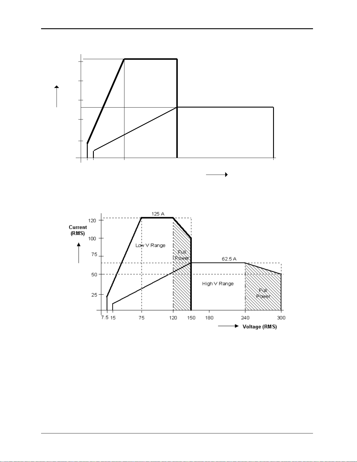
Constant Power Mode:
Operation at higher currents but constant power is possible from 80% of Voltage range
(125% of max. current) declining to 100% of maximum current at 100 % of voltage range
for short periods of time or at reduced ambient temperatures. (< 15 mins @ 30° C). See
Figure 2-2 and Figure 2-4.
AC Mode
MX15-1
V Lo: 100 A
V Hi: 50 A
MX30/2-1
V Lo: 200 A
V Hi: 100 A
MX45/3-1
V Lo: 300 A
V Hi: 150 A
DC Mode
AC+DC Mode
MX15-1
V Lo: 50 A
V Hi: 25 A
MX30/2-1
V Lo: 100 A
V Hi: 50 A
MX45/3-1
V Lo: 150 A
V Hi: 75 A
Note: Current derates linearly from 50% of voltage range to 20% of specified current at 5% of
voltage range
Current Limit mode
Programmable, CC or CV mode
Repetitive Peak Current
AC Mode
MX15-1
V Lo: 300 A
V Hi: 150 A
MX30/2-1
V Lo: 600 A
V Hi: 300 A
MX45/3-1
V Lo: 900 A
V Hi: 450 A
Frequency
Range:
Standard: 16 Hz - 819.0 Hz
-LF option: 16 Hz - 500.0 Hz
-HF option: 16 Hz – 900 Hz
Resolution:
0.01 Hz from 16.00 to 81.91 Hz
0.1 Hz from 82.0 to 819.0 Hz
1 Hz from 819 to 900 Hz
Accuracy:
± 0.01 %
Ext. Sync Mode
Input:
Isolated TTL input for external frequency control. Requires 5V at 5 mA for
logic high.
Accuracy:
Ext. Sync to phase A with fixed Ext. Sync Frequency input:
16 Hz - 100 Hz: < 2°
100 Hz - 500 Hz: < 3°
> 500 Hz: < 4°
Programmable Output Impedance
Range:
R: 1 – 200 mOhm
L: 15 – 200 uH
N/A
N/A
Resolution:
R: 1 mOhm
L: 1 uH
N/A
N/A
Accuracy:
10 % FS
N/A
N/A
Note: Output specifications apply below the Current / Voltage rating lines shown in the
V/I rating chart below.
MX15 13
Page 14
User Manual – Rev M California Instruments
Current
(RMS)
Voltage (RMS)
75 300
100
60
80
40
20
50 A
150
Low V Range
High V Range
100 A
7.5
15
Figure 2-1: MX15-1 Voltage / Current Rating Chart for 150/300 V AC Ranges – Max Rating.
Figure 2-2: Voltage / Current Rating Chart for 150/300 V AC Ranges – Derated.
MX15 14
Page 15
User Manual – Rev M California Instruments
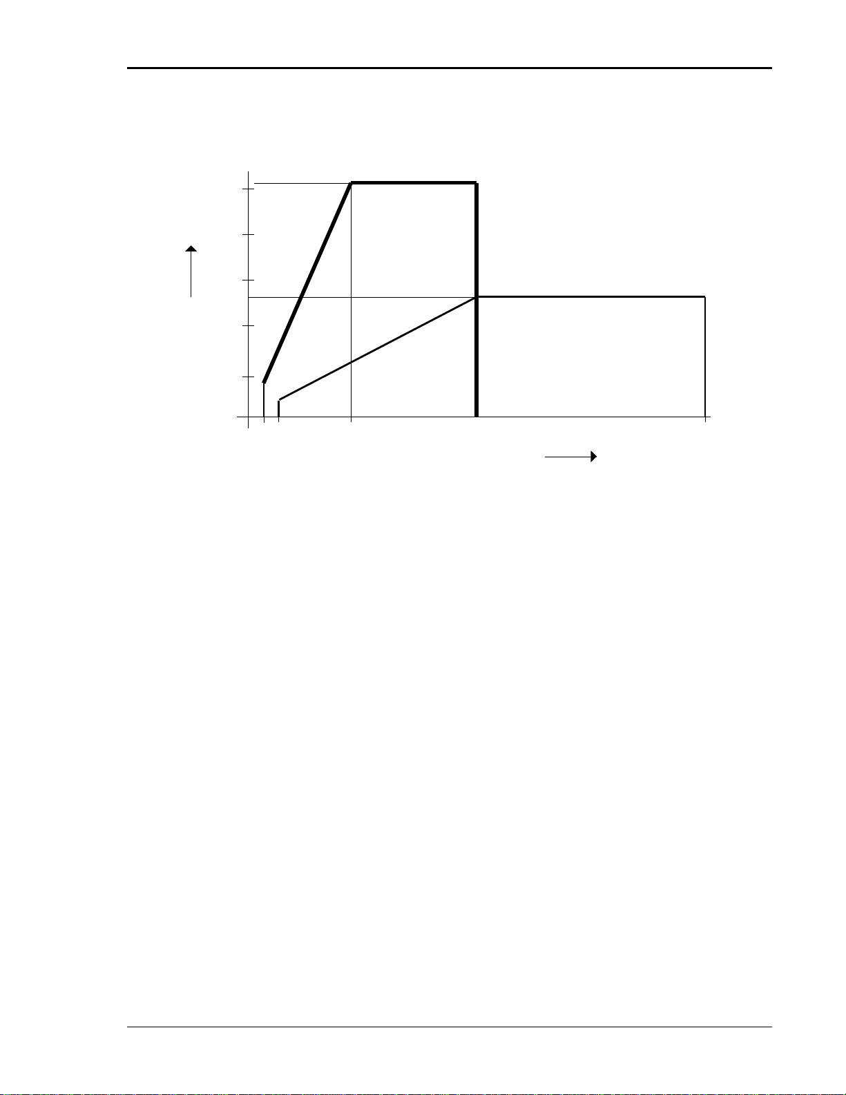
Current
(DC)
Voltage (DC)
100 400
50
30
40
20
10
25 A
200
Low V Range
High V Range
50 A
20
40
Figure 2-3: MX15-1 Voltage / Current Rating Chart for 200/400 V DC Ranges – Max. Rating
MX15 15
Page 16
User Manual – Rev M California Instruments
Parameter
Range
Accuracy ()
Resolution
Frequency
16.00 - 820.0 Hz
0.01% + 0.01 Hz
0.01 to 81.91 Hz
0.1 to 500 Hz
RMS Voltage
0 - 400 Volts
0.05V + 0.02%, <100 Hz
0.01 Volt
RMS Current
0 - 150 Amps
0.15A + 0.02%, <100 Hz
0.01 Amp
Peak Current
0 - 400 Amps
0.15A + 0.02%, <100 Hz
0.01 Amp
VA Power
0 - 15 KVA
30 VA + 0.1%, <100 Hz
10 VA
Real Power
0 - 15 KW
30 W + 0.1%, <100 Hz
60 W + 0.1%, 100-820 Hz
10 W
Power Factor
(>0.2kVA)
0.00 - 1.00
0.01, <100 Hz
0.02, 100-820 Hz
0.01
Note: Accuracy specifications are valid above 100 counts. For current and power measurements,
specifications apply from 2% to 100% of measurement range.
Note: Power factor accuracy applies for PF > 0.5 and VA > 50 % of max.
Current
(DC)
Voltage (DC)
60
50
40
30
20
10
0
20 40 100 150 200 300 400
62.5 A
31 A
25 A
Full
Power
Full
Power
Figure 2-4: Voltage / Current Rating Chart for 200/400 V DC Ranges – Derated
2.1.3 AC Measurements
Measurement specifications apply to MX15-1 / MX15-1Pi. See notes for other models and
configurations.
MX15 16
Page 17
User Manual – Rev M California Instruments
Parameter
Range
Accuracy ()
Resolution
Voltage
0 - 400 Volts
0.5 Volts
0.1 Volt
Current
0 - 400 Amps
0.5 Amps
0.01 Amp
Power
0 - 10 kW
30 W
10 W
Note: Accuracy specifications are valid above 100 counts. For current and power measurements,
specifications apply from 2% to 100% of measurement range.
Parameter
Range
Accuracy ()
Resolution
Frequency fundamental
16.00 - 820 Hz
0.03% + 0.03 Hz
0.01 Hz
Frequency harmonics
32.00 Hz – 16 KHz
0.03% + 0.03 Hz
0.01 Hz
Phase
0.0 - 360.0°
2° typ.
0.5°
Voltage
Fundamental
0.75V
0.01V
Harmonic 2 - 50
0.75V + 0.3% + 0.3%/kHz
0.01V
Current
Fundamental
0.5A
0.1A
Harmonic 2 - 50
0.15A + 0.3% + 0.3%/kHz
0.1A
Note: Accuracy specifications are valid above 100 counts. For current and power measurements,
specifications apply from 2% to 100% of measurement range.
Parameter
Specification
External Modulation:
0 to 10%
Synchronization
Input:
Isolated TTL input for external frequency control. Requires 5V at 5 mA for
logic high.
Trigger Input:
External trigger source input. Requires TTL level input signal. Triggers on
negative edge. Response time 80 - 100 s.
Trigger Output:
Programmable through transient list system. 400 s pulse for voltage or
frequency change. Isolated TTL output. Output reverts to Function strobe
when not used as Trig Out. This function is mutually exclusive with the
Function Strobe output.
Function Strobe:
Active for any voltage or frequency program change. 400 s pulse for voltage
or frequency change. Isolated TTL output. This function is mutually exclusive
with the Trigger Output. Same output is used for Trigger Output if Trigger
Output is programmed as part of list system.
Output Status:
Monitors status of output relay. Isolated TTL output. High if output relay is
closed, low if output relay is open.
Non volatile memory
storage:
16 complete instrument setups and transient lists, 100 events per list.
Waveforms
Sine (Models with Standard controller)
Sine, square, clipped, user defined (Models with Pi controller)
Transients
Voltage: drop, step, sag, surge, sweep
2.1.4 DC Measurements
2.1.5 Harmonic Measurements (Pi controller)
2.1.6 System Specification
MX15 17
Page 18
User Manual – Rev M California Instruments
Parameter
Specification
Frequency: step, sag, surge, sweep
Voltage and Frequency: step, sweep
IEEE-488 Interface:
SH1, AH1, T6, L3, SR1, RL2, DC1, DT1
IEEE 488.2 and SCPI
Response time is 10 ms (typical)
RS232C Interface:
Bi-directional serial interface
9 pin D-shell connector
Handshake: CTS, RTS
Data bits: 7, 8
Stop bits: 1,2
Baud rate: 9600 to 115,200 bps
Syntax: IEEE 488.2 and SCPI
USB Interface:
Standard USB 2.0 peripheral.
Data transfer rate: 460,800 bps
Syntax: IEEE 488.2 and SCP.
Note: Use of the USB port to control more than one power source
from a single PC is not recommended, as communication may not be
reliable. Use GPIB interface for multiple power source control.
Note: Not available on older MX15 models.
LAN Interface:
Option –LAN. When the LAN interface is installed, the RS232 interface is
disabled.
RJ45 Connector, 10BaseT, 100BaseT or 1000BaseT,
Data transfer rate: 460,800 bps
Protocol: TCP/IP.
Syntax: IEEE 488.2 and SCP
Note: Disconnect any USB connection when using the LAN interface.
Current Limit Modes:
Two selectable modes of operation:
1. Constant current mode (voltage folds back with automatic recovery)
2. Constant voltage mode with trip-off (Relays open).
MX15 18
Page 19
User Manual – Rev M California Instruments
Input Over current:
In-line fast acting fuses. Check fuse rating in Service and Maintenance
section. Ratings will depend on AC input configuration settings.
Circuit breaker for LV supply.
Input Over voltage:
Automatic shutdown.
Input Over voltage
Transients:
Surge protection to withstand EN50082-1 (IEC 801-4, 5) levels.
Output Over current:
Adjustable level constant current mode with programmable set point.
Output Short Circuit:
Peak and RMS current limit.
Over temperature:
Automatic shutdown.
Parameter
Specification
Dimensions:
(for each MX chassis)
Height: 31.75” 806 mm
Width: 24” 610 mm
Depth: 28” 711 mm
Unit Weight:
(for each MX chassis)
Net: 600 lbs / 272 Kg approximately
Shipping: 681 lbs / 309 Kg approximately
Material:
Steel chassis with aluminum panels and covers.
Finish:
Light textured painted external surfaces.
Panels semi-gloss polyurethane color no. 26440 (medium gray)
Cooling:
Fan cooled with air intake on the front and exhaust to the rear.
Fans: 2 x 225CFM.
Air displacement 7.5 Cu Ft/sec. Max.
Internal Construction:
Modular sub assemblies.
Rear Panel
Connections:
(See section 3 for description of connections)
Cable entry and strain relieve for AC input wiring
Cable entry and strain relieve for output wiring
External sense terminal block (Remote voltage sense)
System interface (2x)
Clock and Lock BNC's (requires -LKM or -LKS options)
RS232, USB, GPIB, LAN (option)
Trigger In BNC
Trigger Out BNC
Function Strobe BNC
Output Status
2.1.7 Unit Protection
2.2 Mechanical
MX15 19
Page 20
User Manual – Rev M California Instruments
Parameter
Specification
Operating Temp:
0° to +40 C. (Except in CP mode).
+32° to +104° F.
Storage Temp:
-40° to +85 C.
-40° to +185° F.
Altitude:
< 2000 meters
Relative Humidity:
0-95 % RAH, non-condensing maximum for temperatures up to 31C
decreasing linearly to 50% at 40C.
Installation/Over voltage
Category:
Pollution Degree:
2
Indoor Use Only
Vibration:
Designed to meet NSTA 1A transportation levels.
Shock:
Designed to meet NSTA 1A transportation levels.
Electromagnetic
Emissions and Immunity:
Designed to meet EN50081-2 and EN50082-2 European Emissions and
Immunity standards as required for the “CE” mark.
Acoustic Noise:
56 dBA maximum at 0% to 50% load, 68 dBA maximum greater than
50% load to 100% load. Measured at one meter.
Safety:
Designed to EN 61010-1 European safety standards as required for the
“CE” mark.
Controls:
Shuttle knob:
Allows continuous change of all values including output calibration and
range change.
Decimal keypad:
A conventional decimal keypad facilitates quick entry of numerical values
such as voltage, current limit, etc. The large blue enter key will make the
value you enter effective. Using the SET key allows the user to preset all
parameter values and update them all at once by pressing the Enter key.
Up/down arrow keys:
A set of up and down arrow keys is used to move the cursor position in
all menus. This allows quick selection of the desired function or
parameter.
Function keys:
Measure key will display most measurement values. Program key will
show all program parameters. Output on/off key for output relay control.
Phase key will switch display to show program and measured values for
each phase (not used on MX15).
2.3 Environmental
2.4 Regulatory
2.5 Front Panel Controls
MX15 20
Page 21
User Manual – Rev M California Instruments
Displays:
LCD display:
A two-line LCD display with backlight provides easy to read guidance
through all setup operations. An adjustable viewing angle makes it easy
to read from all practical locations.
Status indicators:
Bright status indicators inform the user of important power source
conditions. The Remote lamp informs the user that the unit is under
remote control. The Overload lamp indicates that excessive current is
being drawn at the output. The Over temperature lamp illuminates when
internal heat sink temperatures are too high. The Hi Range indicator is
lit any time the unit is switched to the high voltage range. The Output
On/Off indicator is on when the power source output relays are closed.
Controller Features
Mode:
This option is not available for the MX15.
Parallel Operation:
Up to three units can be paralleled in a single-phase configuration (with
one master controller and one or two auxiliary units). (MX30/2 and
MX45/3). Only the master unit requires a controller in this setup. The
auxiliary units are controlled through the system interface.
Clock and Lock Mode:
(Option -LKM and -LKS
required).
Up to three units (all with controllers) can be connected in a one, two, or
three-phase configuration using CLOCK and LOCK connections. Each
unit requires its own controller in this configuration. One unit acts as the
master and provides the reference clock to the auxiliary units.
Controller:
Programmable controller front panel assembly.
Output Relay:
Standard output relay feature to isolate power source from the load.
Output On/Off:
The output relay can be used to quickly disconnect the load. An amber
status indicator displays the status of the output relay.
Firmware Options
- 704
Mil Std 704D & E test firmware.
Mil Std 704A, B, C, & F test software (refer to Avionics Software Manual
P/N 4994-971 for details).
Note: Requires use of MXGui Windows application software provided on
CD ROM CIC496.
- 160
RTCA/DO-160D test firmware
RTCA/DO-160E test software (refer to Avionics Software Manual P/N
4994-971 for details)..
Note: Requires use of MXGui Windows application software provided on
CD ROM CIC496.
-411
IEC 61000-4-11 Voltage Dips and Interruptions Test firmware. Supported
over remote control interface only.
-413
IEC 61000-4-13 Interharmonics Test Firmware. Supported over remote
control interface only.
787
Boeing 787 Test software (refer to Avionics Software Manual P/N 4994971 for details)..
Note: Requires use of MXGui Windows application software provided on
CD ROM CIC496.
-ABD
Airbus ABD0100.1.8 Test software (refer to Avionics Software Manual
P/N 4994-971 for details).
Note: Requires use of MXGui Windows application software provided on
2.6 Special Features and Options
MX15 21
Page 22
User Manual – Rev M California Instruments
CD ROM CIC496.
-WHM
Watt Hour Measurements (Accuracy and Resolution. See Sec. 2.6.5.)
Output Voltage Range Options
- HV
Adds 400 V AC only output range.
- XV
Adds customer specified AC only output range. Contact factory for
details.
Misc. Options
-ES
Emergency Shut off switch. This option key lock push button is installed
on the front panel of the master MX if ordered with the MX system. When
pushed in, the main AC contactor is opened disconnecting the AC input
power to the MX input transformer. Note that the controller (and LCD
display) will still be powered up but no power is available to the
amplifiers and there will be no output power either. The controller runs
off the LV supply, which must be turned off with the front panel breaker.
After the ES has been pushed, the provided key will be required to
release it. Once the ES button has been released, the MX must be
powered down using the front panel circuit breaker and turned back on
to start up again.
Note: Do not misplace the 2 keys provided, as no duplicates are
available from CI. If lost, the ES switch must be replaced. In that case,
contact AMETEK Programmable Power customer service.
(service@programmablepower.com ).
-MB
Multi-box Option. Provides additional controllers in Auxiliary units of
multi-cabinet configurations (MX30/2, MX45/3) to allow individual MX15
units to be used stand-alone.
-LF
Limits maximum output frequency to 500 Hz.
-HF
Increases maximum output frequency to 900 Hz.
External Accessories (External to MX chassis)
7003-416-1
Input / Output wiring junction box. Connects two to six three-phase
MX45 cabinet outputs, neutral and ground to a common output
terminal block housed in a metal enclosure junction box. Can also
be used to connect multiple MX chassis to common AC input
service. See section 3.13 for details.
7003-424-1
Output noise filter, 3 phase + neutral. May be used to reduce output
noise of MX15 when testing EUT’s for conducted emissions. This is an
external filter that attenuates the 250 KHz ripple frequency on the MX
output by > 20 dB. The filter is rated for 125A per phase and 800 Hz.
MX15 22
Page 23
User Manual – Rev M California Instruments
Output Parameter
MX15
MX30/2
MX45/3
Modes
Pi Controller
AC
Voltage:
Ranges (L-N):
0 -400 V
Resolution:
0.1 V
Accuracy:
± 0.4 V
Output Coupling
AC coupled
Power (total power for all phases, either range, at full scale voltage)
AC Mode
15 KVA
30 KVA
45 KVA
Current
Note: Current, maximum amps per phase available between 50 and 100 % of voltage range.
MX15-1
37.5 A
MX15-1
75 A
MX15-1
112.5 A
Peak Current
AC Mode
MX15-1
112.5 A
MX15-1
225 A
MX15-1
337.5 A
2.6.1 -HV Option Specifications
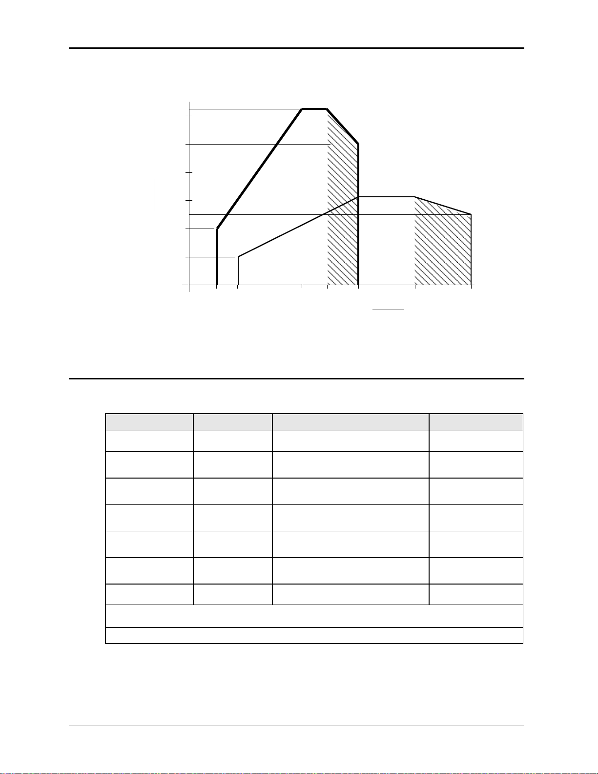
The -HV option provides an AC only output range of 0 to 400 Vac L-N. Specifications unique to
the -HV option are shown in the table below.
MX15 23
Page 24
User Manual – Rev M California Instruments
Current
(RMS)
Voltage (RMS)
100 200 300 400
37.5
37.5 A
-HV Range
20
Note: Output specifications apply below the Current / Voltage rating lines shown in the
V/I rating chart below.
Figure 2-5: MX15-1 Voltage / Current Rating Chart, -HV Option – Max. Rating.
Figure 2-6: Voltage / Current Rating Chart, -HV Option – Derated.
MX15 24
Page 25
User Manual – Rev M California Instruments
-HF Option:
Frequency
Range:
-HF option: 16 Hz - 900 Hz
Resolution:
0.01 Hz < from 16.00 to 81.92 Hz
0.1 Hz > from 82.0 to 819.2 Hz
1 Hz > from 820 to 900 Hz
Accuracy:
± 0.01 %
Phase
Accuracy:
16 - 100 Hz: < 1.5°
100 - 500 Hz: < 2°
500 – 819 Hz: < 4°
819 – 900 Hz: < 5°
Voltage
High Voltage Range
Maximum voltage at 900 Hz is 290 Vrms
Maximum frequency at 300 Vrms is 875 Hz
See Figure 2-7
Low Voltage Range
Maximum voltage at 900 Hz is 145 Vrms
Maximum frequency at 150 Vrms is 875 Hz
See Figure 2-8.
-HV Voltage Range
Maximum voltage at 900 Hz is 386 Vrms
Maximum frequency at 400 Vrms is 875 Hz .
Note: If the voltage or frequency settings shown here are exceeded for
any length of time (> 1 sec), the MX may shut down generating an over
temperature fault to protect itself.
2.6.2 -XV Option Specifications
Consult factory for -XV option specifications.
2.6.3 -HF Option Specifications
The -HF option extends the maximum available output frequency from 819 Hz to 900 Hz. Some
restrictions are in effect at this increased output frequency level.
All other specifications of the MX15 system remain unchanged if this option is installed except as
noted in the table below.
MX15 25
Page 26
User Manual – Rev M California Instruments
Figure 2-7: -HF Option Voltage Frequency Rating 300V range
Figure 2-8: -HF Option Voltage Frequency Rating 150V range
MX15 26
Page 27

User Manual – Rev M California Instruments
2.6.4 -LF Option Specifications
The -LF option limits the maximum available output frequency to 500 Hz. All other specifications
of the MX15 system remain unchanged if this option is installed.
2.6.5 WHM Option Specifications
Watt-hour measurement mode:
Accuracy:
0-6.000KW 0.01KWH + 0.1% <100 Hz
0.02KWH +0.1% 100-819 Hz
>6.000KW Times three of the above specification
Resolution:
0.01 KWH
MX15 27
Page 28
User Manual – Rev M California Instruments
-SNK Option: The following specifications apply to the AC mode unless specified otherwise
Frequency
Range:
-HF option: 16 Hz - 500 Hz
Resolution:
0.01 Hz < from 16.00 to 81.92 Hz
0.1 Hz > from 82.0 to 500.0 Hz
Accuracy:
± 0.01 %
Phase
Accuracy:
16 - 100 Hz: < 1.5°
100 - 500 Hz: < 2°
Voltage
Distortion THD1:
(Resistive full load)
< 1 % @ 16 - 66 Hz
< 2 % @ 66 - 500 Hz
Power
Capability (AC & DC)
Full power can be returned into MX as long as current does not exceed
maximum current limit setting for selected range. See REGENERATE
CONTROL screen for protection settings in REGEN mode.
Without –SNK option
MX units without the SNK will generate a warning message (Error 31) if
more than 20% of available power (per phase) is regenerated by the load.
It will shut off (Error 32) if the negative power reaches 30% of available
power.
Programmable Output Impedance (available on MX15-1Pi, MX30-30Pi and MX45-3Pi only)
Auto-disabled
Programmable impedance is turned off as soon as a regenerative load is
detected. Once turned off, it will remain off until programmed by user
again. This is required as programmable impedance is based on
delivering current which is not the case when driving a regenerative load.
Measurements
Power
Regenerated power is displayed with a negative sign to indicate direction
of power flow.
1
2.6.6 SNK Option Specifications
The –SNK or current sink option enables the MX power source to sink current from the unit
under test. This mode of operation is particularly useful when testing grid-tied products that feed
energy back onto the grid. The ability of the MX to simulate the grid provides unique opportunities
to test the EUT for compatibility to commonly occurring line anomalies like voltage and/or
frequency fluctuations. Examples of these types of EUT are inverters (PV Solar, Wind) hybrid
drive systems, regenerative breaks.
The SNK option requires special amplifiers that have a different control loop from the standard
MX amplifiers. In the AC mode the upper frequency limit of an MX configured with the –SNK
option is 500Hz as opposed to the standard 819Hz. Also, the voltage distortion levels are slightly
higher than on MX units without this option.
All other specifications of the MX system remain unchanged if this option is installed.
The distortion specification for the MX Series is valid for pure (inductance < 12 uH) resistive load conditions and
using a 30 KHz LP filter on distortion meter.
MX15 28
Page 29
User Manual – Rev M California Instruments
Output Parameter
MX15
MX30/2
MX45/3
Voltage:
Slew rate:
> 0.5 V/micro sec
Stability:
0.25 % over 24 hour period at constant line, load and temperature.
Settling time:
< 0.5 msec
Frequency:
Temperature
coefficient:
5ppm per degree C
Stability:
15 ppm per year
Current:
Constant Power
Mode:
Operation at higher currents but constant power is possible from 80% of
Voltage range (125% of max. current) declining to 100% of maximum current
at 100 % of voltage range for short periods of time or at reduced ambient
temperatures. (< 15 mins @ 30° C). See Figure 2-2 and Figure 2-4.
Acoustic Noise:
Measured at a distance of one meter. (3 ft.)
Front
53 dBA at no load to 65 dBA at full load.
Back
55 dBA at no load to 67 dBA at full load
2.7 Supplemental Specifications
Supplemental specifications are not warranted and generally reflect typical performance
characteristics. These characteristics are have been checked on a type test basis only and are
not verified on each unit shipped. They are provided for reference only.
2.7.1 Output
2.7.2 Acoustic Noise Levels
MX15 29
Page 30
User Manual – Rev M California Instruments
MX Filter Specifications
(Model 7003-424-1)
Type
Low Pass Filter
Three phase WYE, four wire. (A, B, C and Neutral)
Capability
Frequency range
DC, 16 Hz - 800 Hz
Max Voltage
250 Vrms Line to Neutral / 440 Vrms L-L
Phase Current
125 Arms per phase maximum.
Impedance
Voltage drop at 800 Hz, 125 A is less than 1 Vrms.
Performance
Attenuation
20 dBuV at 250 KHz.
Physical
Enclosures type
Cooper B-Line P/N 16126 SC NK
Dimensions (W x D x H)
Unit: 16” x 12” x 6” / 406 mm x 305 mm x 152 mm
Shipping: 30” x 25” x 11” / 760 mm x 635 mm x 280 mm
Weight
Net: 28 lbs / 12.7 Kg
Shipping: 40 lbs / 18.2 Kg
Operating Temp:
0° to +40 C. / +32° to +104° F.
2.7.3 Output Noise Spectrum
The MX series is a switching power supply and as such will have a certain amount of switching
noise at its output. While the overall RMS noise is specified, the specific noise spectrum will
differ slightly from unit to unit. The information provided in this section is for reference only.
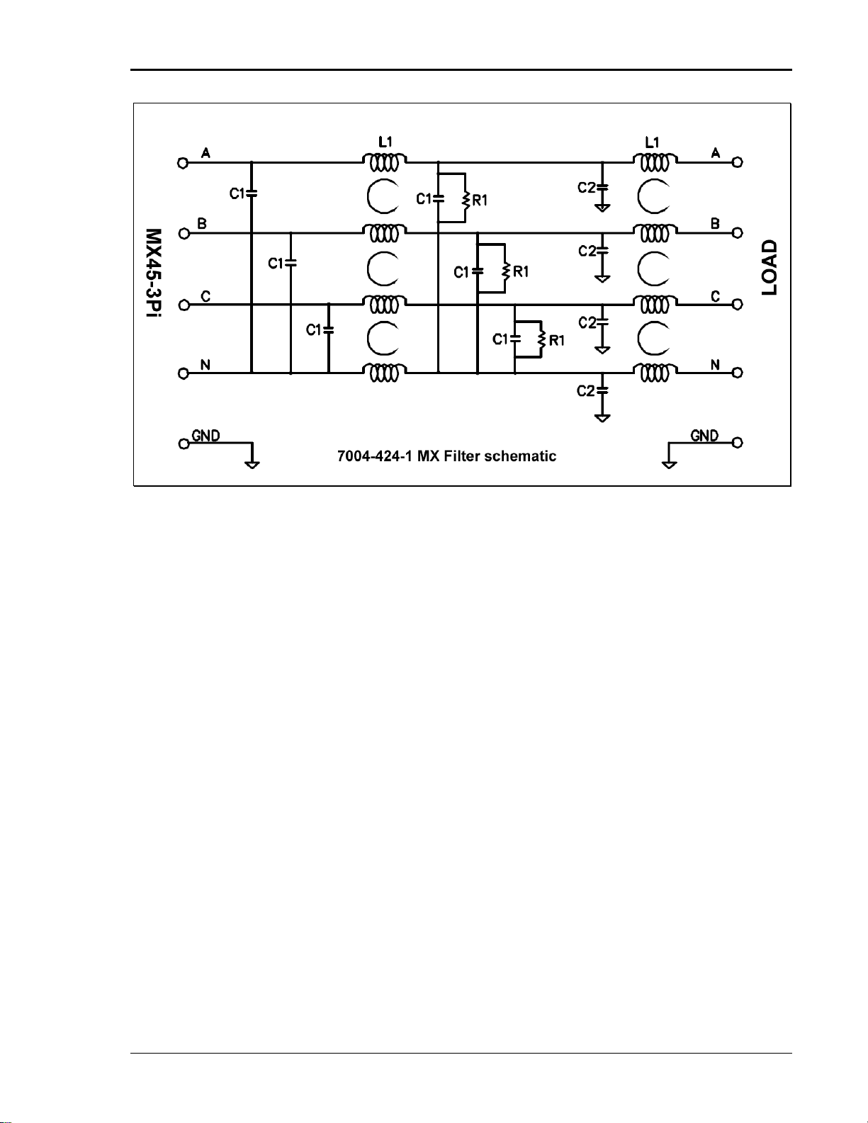
The output noise can be reduced by using one or more external filters. A suitable filter is the P/N
7003-424-1 (Figure 2-9) available from AMETEK as an option. Attenuation at the 250 kHz ripple
frequency is 20 dBuV. The output voltage drop at 800 Hz full load is less than 1Vrms.
Typical output noise spectrum for a standard MX45-3Pi in three phase mode operating at 400 Hz
is shown in Figure 2-10 for phase A and Neutral. The same output with the use of the optional
filter is shown in Figure 2-11. For connection information, refer to section 3.14. The MX15 and
MX45 use the same amplifier so results will be similar.
MX15 30
Page 31
User Manual – Rev M California Instruments
Figure 2-9: MX output filter option schematic
MX15 31
Page 32

User Manual – Rev L California Instruments
Figure 2-10: MX45 Output Noise 10 KHz – 1 MHz
MX15 32
Page 33

User Manual – Rev L California Instruments
Figure 2-11: MX45 Output Noise 10 KHz - 1 MHz with optional Filter
MX15 33
Page 34

User Manual – Rev M California Instruments
3 Unpacking and Installation
3.1 Unpacking
Inspect the unit for any possible shipping damage immediately upon receipt. If damage is
evident, notify the carrier. DO NOT return an instrument to the factory without prior approval. Do
not destroy the packing container until the unit has been inspected for damage in shipment. If
possible, retain the container (wooden crate) in the event the system ever has to be returned to
the factory for either repair or upgrades
WARNING: This power source weighs approximately 600 lbs / 272 Kg. Obtain
adequate help when moving the unit. Make sure the location (floor) in which the MX
Series unit(s) will be installed can support the weight of the unit(s).
3.2 Power Requirements
The MX Series power Source has been designed to operate from a three-phase, three wire (Wye
or Delta) AC input line. A protective earth connection is required as well. (PE).
Available three-phase input settings are 208 V
(option -400), 440 V
(option -440), or 480 V
LL
Figure 3-1: The MX15 Power Source
LL
(option -208), 230 V
LL
(option -480).
(option -230), 400 V
LL
LL
CAUTION: Do not connect 400, 440, or 480V into a unit set for 208 or 230V unit, the
result could be a severely damaged unit. Always check the input rating on the model
number tag before connecting AC input power. Consult factory if input settings have
to be changed.
MX15 34
Page 35
User Manual – Rev M California Instruments
3.3 Mechanical Installation
The MX's are completely self-contained power sources. They are to be used free standing on a
solid surface. The units are fan cooled, drawing air in from the front and exhausting at the rear.
The front and back of each unit must be kept clear of obstruction and a 6” clearance must be
maintained to the rear. Special consideration of overall airflow characteristics and the resultant
internal heat rise must be considered at all times to avoid self heating and over temperature
problems.
3.4 AC Input Connections and Wiring
Three-phase Delta or Y AC input voltage of sufficient amperage (consult AC input specifications
for maximum AC current per phase) is required to power the MX Series.
Note: AC power should be routed through a properly sized and rated three-phase
PROTECTIVE CIRCUIT BREAKER or similar branch circuit protection device with
disconnect capability. This will protect building wiring and other circuits from
possible damage or shutdown in case of a system problem. It will also facilitate
removing AC input power to the MX system in case of service or reconfiguration
requirements.
Note: AC input wiring and connections must conform to local electrical safety codes
that apply. Always consult a qualified electrician prior to installation of any MX
System.
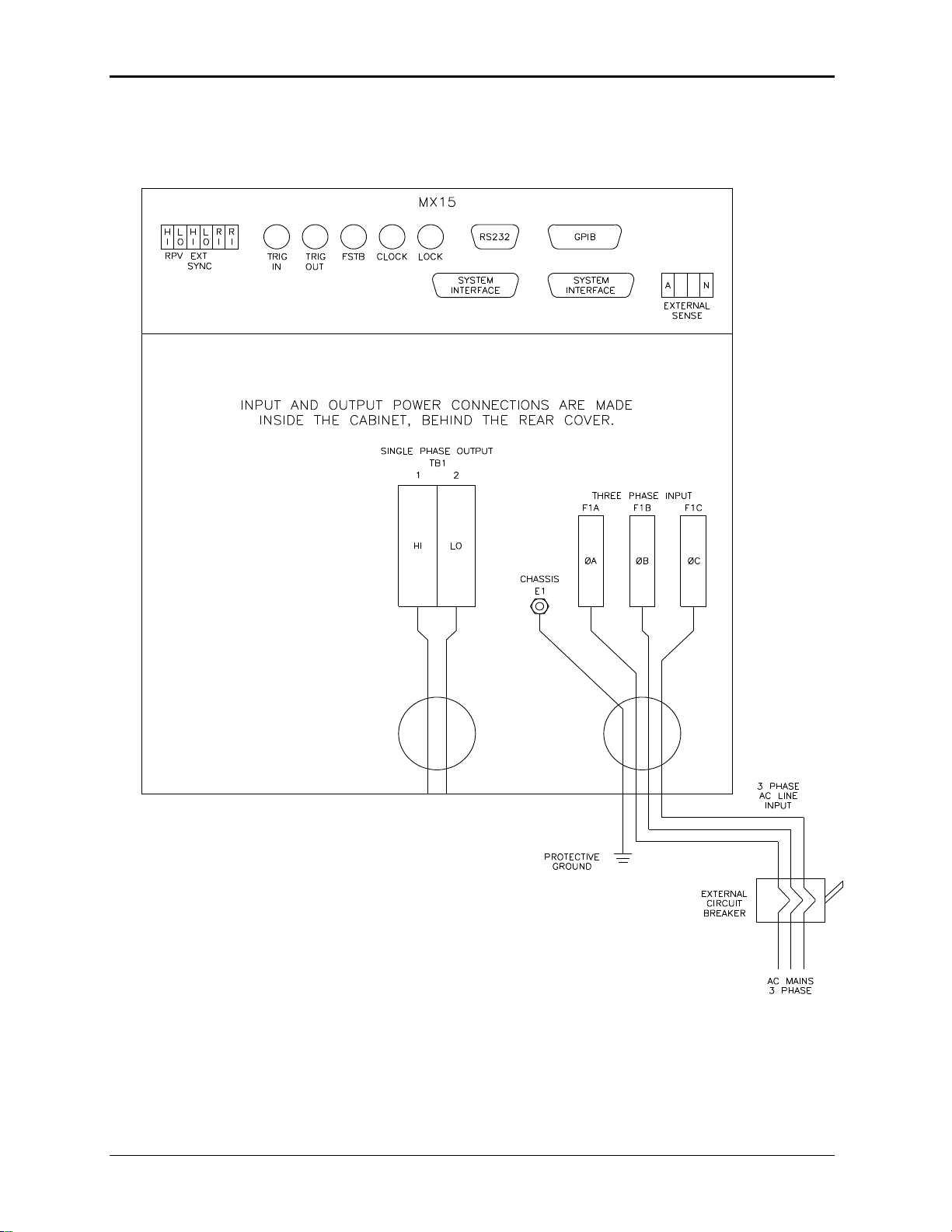
AC input connections are to be made directly to the input fuse block. The input fuse block is
located on the lower right hand corner of the back of the MX15 chassis. To access the input fuse
connection block, the protective rear cover needs to be removed first.
CAUTION: Always disconnect any input power completely when removing
any protective cover and allow the internal capacitors to fully discharge
(minimum of 15 mins) before removing any cover. See Figure 3-2 for details.
No wiring for AC input connections is provided with the MX Series and must be provided by the
end user or installer. Input wiring should be entered through the right hand side (when facing the
back of the MX cabinet, see Figure 3-4) wire access opening located at the rear bottom of the
MX15 chassis.
MX15 35
Page 36

User Manual – Rev M California Instruments
Figure 3-2: Location of AC Input Fuse Block and Chassis Ground Connection -
Rear View, Access Panel Removed
Note: To comply with product safety requirements, EARTH GROUND must be connected
to the chassis of the AC power system using the ground stud located directly
below the inrush resistors. Use a Green/Yellow ground wire.
Note: DO NOT USE THE NEUTRAL CONNECTION OF A 3 PHASE Y AC POWER
CONNECTION IN PLACE OF A TRUE EARTH GROUND CONNECTION. AC power
system neutrals cannot be used for protective earth ground.
The mains source must have a current rating equal to or greater than the input fuses and the
input wiring must be sized to satisfy the applicable electrical codes. The rear cover must be reinstalled prior to use and the strain relief provisions located at the rear bottom of the unit must be
used to maintain protection against hazardous conditions.
MX15 36
Page 37

User Manual – Rev M California Instruments
MX15 37
Page 38
User Manual – Rev M California Instruments
Figure 3-3: MX Series AC Input Connection Diagram (Rear view)
MX15 38
Page 39
User Manual – Rev M California Instruments
Nominal Line
Voltage
Load Current
@ low line
Wire Gauge (US)
Circular Mils
(Kcmils)
Metric (mm2)
480 V
25 Arms
8 AWG
11.50
5.8
400 V
30 Arms
8AWG
11.50
5.8
230 V
52 Arms
8 AWG
18.00
9.1
208 V
58 Arms
6 AWG
26.24
13.3
The input power cables and protective circuit breaker used must be large enough to handle the
input current and input voltage of the power source and must conform to local electrical codes.
Consult a qualified electrician prior to installation. Table 3-1 shows the size of the cables that
may be used per MX15 cabinet. Note that wires must be sized to accommodate the worst-case
maximum current that may occur under low line conditions. Local electrical codes may also
require different wire types and sizes. These ratings should also be used when selecting a circuit
breaker or equivalent disconnect device.
Cable lengths must not exceed twenty-five (25) feet. For lengths greater than 25 feet, calculate
the voltage drop from the following formula:
2 X DISTANCE X CABLE RESISTANCE PER FT. X CURRENT = VOLT DROP
Table 3-1: Suggested Input Wiring Sizes for each MX Cabinet *
* Using high temperature rated wire. Always consult the National Electrical Code and/or local code
regulations for proper rating and size of wire cabling prior to installation.
CAUTION: Capacitors in the power source may hold a hazardous electrical charge
even if the power source has been disconnected from the mains supply. Allow
capacitors to discharge to a safe voltage before touching exposed pins of mains
supply connectors.
Power modules need at least 15 Minutes to discharge to safe levels before they can be
removed.
3.5 AC On/Off Circuit Breaker on MX Series front panel.
It is important to understand the purpose and operation of the On/Off circuit breaker of the MX15
located on the left side of the front panel. This is a 2A rated breaker that is used to engage and
protect the LV Power supply of the MX15 chassis only. The LV Power supply provides DC bias
power to the entire MX15 system. The AC input power is routed through a set of three AC line
fuses (F1, F2 and F3) located in the lower right bottom corner of the MX15. (See Figure 3-2 for
fuse locations). These fuses protect the MX amplifier and the AC input transformer from
excessive input currents. The AC input power is connected to the input transformer through a
large three-pole contactor. Removing AC power to the LV Power Supply by opening the front
panel circuit breaker (moving the lever to the down (OFF) position) will cause this contactor to
loose its coil voltage and will result in it opening and disconnecting the input transformer and
amplifier from AC mains input.
Note: If any MX15 system failure has occurred on any part of the MX15 system, AC input
power must be removed immediately and not restored until the system has been
inspected by a qualifier service technician.
Always turn off the On/Off Circuit breaker before re-applying AC input power.
MX15 39
Page 40

User Manual – Rev M California Instruments
CAUTION: The AC input fuses can only be checked if the MX unit is completely
de-energized and disconnected from any AC power input.
Note: Under no circumstances should AC input power be applied if one or more of the
AC input line fuses have failed and opened up.
Figure 3-4: Rear Panel
MX15 40
Page 41

User Manual – Rev M California Instruments
Shield
Connection
3.6 Output Connections
3.6.1 Output Wiring
The output terminal block, TB1, is located at the back of the unit behind the bottom access panel.
See Figure 3-2 for details.
Single phase output line connections are made to terminal block TB1. The outputs are labeled HI
and LO.
The external sense inputs allow the power system output voltages to be monitored directly at the
load and must be connected at TB2 when the sense is programmed for external. The external
sense input does not have to be connected when Internal Sense is programmed. The external
sense wires are to be connected to TB2 on the rear panel and should be run using a twisted
shielded cable. See Figure 3-4 for location of TB2 and Figure 3-5 for shield connection detail.
Note: For External Sense connection, a shielded cable MUST be used with the shield
connected to chassis ground at the Ext. Sense connector. (See Figure 3-5).
External sense is recommended for multi-cabinet systems where the output wiring from the
cabinets to the common output terminal block supplied is not of equal length.
Figure 3-5: External sense cable shield connection to chassis ground
Note: The output of the power source is isolated from the input line and floating with
respect to chassis ground. If needed, either side (HI or LO) may be grounded.
If the EUT changes frequently, you may want to consider using some quick disconnect scheme
external to the MX15 so it will not be necessary to power down the MX15 and remove the front
covers. This can take the form of a panel-mounted socket of sufficient current and voltage
rating. (Not supplied with MX15)
The output power cables must be large enough to prevent a total voltage drop exceeding 1% of
the rated output voltage between the power source and the load. Table 3-2 shows the size of the
cables that may be used. Note that wires must be sized to accommodate the maximum current
that is available. Size the wires for the lowest available voltage range as the currents will be
highest in that range.
MX15 41
Page 42
User Manual – Rev M California Instruments
Load Current
Wire Gauge (US)
Circular Mils
(kcmils)
Metric (mm2)
65 AMPS
6 AWG
26.24
13.3
130 AMPS
4 AWG
41.74
21.1
Cable lengths must not exceed twenty-five (25) feet. For lengths greater than 25 feet, calculate
the voltage drop from the following formula:
2 X DISTANCE X CABLE RESISTANCE PER FT. X CURRENT = VOLT DROP
Table 3-2: Suggested Output Wiring Sizes *
Note: Use high temperature rated wire. Always consult the National Electrical Code
and/or local code regulations for proper rating and size of wire cabling prior to
installation.
MX15 42
Page 43
User Manual – Rev M California Instruments
Output Terminal Blocks
The MX15-1 and the MX15-1Pi have one output terminal block. The terminal block is large
enough to accommodate the recommended wire gauge sizes shown in Table 3-2. The terminal
block is located in the lower left corner on the rear of the unit. The rear panel needs to be
removed to access this terminal block.
CAUTION: REMOVE ALL INPUT POWER TO THE MX15 BEFORE
REMOVING THE REAR PANEL.
The correct standard size Allen wrench for connecting output wiring to TB1 is supplied with each
MX15 in the ship kit. Look for a brown envelope. If the correct tools cannot be found, contact
AMETEK Programmable Power customer service at service@programmablepower.com .
Terminal 2 of TB1 provides the output LO connection, and terminal 1 of TB1 provides the output
HI connection. The location of TB1 is shown in Figure 3-2.
3.6.2 MX15-1, MX15-1Pi Output Wiring Diagram
Figure 3-6 shows the required output connections for a MX15-1 and MX15-1Pi (rear-view
perspective).
Always disconnect all input power from the MX before removing the rear panel cover that
provides access to the input and output terminal connections.
Figure 3-6: MX15-1 Output Wiring (Rear view)
MX15 43
Page 44

User Manual – Rev M California Instruments
3.6.3 MX30/2 Output Wiring Diagram
Figure 3-7 shows the required output connections for an MX30/2-1 single-phase output configuration (rear-view perspective). Always
disconnect all input power from the MX30/2 before removing the rear panel cover that provides access to the input and output terminal
connections. MX30/2 systems are shipped with external output terminal blocks that enable the output wiring from two or three chassis to
be combined, providing a single point of connection to the EUT. These blocks are not enclosed however.
Figure 3-7: MX30/2 or MX30/2-MB Output Wiring (Rear view)
MX15 44
Page 45
User Manual – Rev M California Instruments
Figure 3-8: Two MX's in Clock and Lock mode Output Wiring (Rear view)
MX15 45
Page 46
User Manual – Rev M California Instruments
MX135 Output Wiring Diagram
Figure 3-9 shows the required output connections for an MX45/3-1Pi or MX45/3-1Pi-MB single-phase output configuration (rear-view
perspective). Always disconnect all input power from the MX45/3 before removing the rear panel cover that provides access to the input
and output terminal connections. Note that the master is shown in the center in this drawing. MX45/3 systems are shipped with external
output terminal blocks that enable the output wiring from two or three chassis to be combined, providing a single point of connection to the
EUT. These blocks are not enclosed however.
Figure 3-9: MX45/3 or MX45/3-MB Output Wiring (Rear view)
MX15 46
Page 47
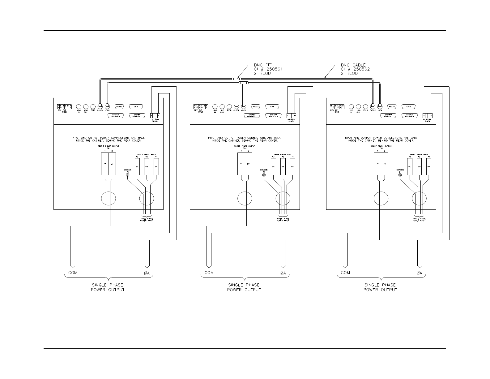
User Manual – Rev M California Instruments
Figure 3-10: Three MX's in Clock and Lock mode - Output Wiring (Rear view)
MX15 47
Page 48

User Manual – Rev M California Instruments
3.6.4 Multi-Chassis Output Connections
If two or more MX15 chassis are used to form a single power system, the outputs of all chassis
need to be combined (paralleled). This can be done directly at the EUT if convenient or using
the provided heavy-duty terminal block. One 2-position block is provided. This block allows up to
four wires to be combined into one larger wire gauge size wire. The outputs of the 2 or 3 MX15
chassis are connected on one side of these blocks. The EUT can be connected to the other side.
Note that the wire size to the EUT should be sized up to accommodate the double or triple
currents per phase.
The dimensions of the supplied terminal block are shown in Figure 3-11.
Figure 3-11: Ship kit Terminal Block dimensions
MX15 48
Page 49

User Manual – Rev M California Instruments
P8 / P9
Description
1
OUTP: Output ON. Controls state of output relay
2
N/C 3 N/C 4 N/C 5 COM: Common. Signal return.
6
OT: Over temperature. Indicates over temperature condition.
7
N/C 8 CLB: Current Limit B. (Not Used)
9
CSA: Current Sum Phase A
10
CSC: Current Sum Phase C (Not Used)
11
FLT A: Amplifier Fault Phase A
12
FLT C: Amplifier Fault Phase C (Not Used)
13
XFMR: Optional voltage range select. (-HV or -XV option)
14
PARALLEL: Parallel operation control. (Not Used)
15
INPUT ON: Input power status
16
A ERR LO: Error Signal Phase A, low
17
B ERR HI: Error Signal Phase B, high (Not Used)
18
N/C
19
C ERR LO: Error Signal Phase C, Low (Not Used)
20
300 VRNG: 300 V AC Range Select
3.7 Connectors - Rear Panel
A number of connectors are located along the top rear covers. These connectors are in a
recessed area to protect them from shipment damage.
3.7.1 System Interface
WARNING: The system interface connectors are for use with AMETEK supplied
cables, and only between California Instruments equipment.
The Clock and Lock BNC connectors located on the rear panel are used to synchronize and
control the phase shift between the three outputs when 3 units are operating as a three-phase
clock and lock system. This mode of operation requires the -LKM (on Master unit) and -LKS (on
Auxiliary units) options. See paragraph 3.10 for more information on this mode of operation.
A set of two identical System Interface connectors, P8 and P9 is located on the rear panel of
each MX15 chassis. The system interface is used to connect the multiple MX15 power sources
in a Master/Auxiliary configuration to create MX30/2 or MX45/3 models. In these configurations,
only the Master MX15 power source has a built-in controller and front panel.
The same connector is also used to control the optional OMNI-3-75 Reference Impedance.
MX15 49
Page 50

User Manual – Rev M California Instruments
P8 / P9
Description
21
COM: Common. Signal return.
22
/REM OFF: Remote Off Control not
23
COM: Common. Signal return
24
FLK/BYP: Flicker / Bypass OMNI control
25
/OVL: Overload not
26
CLA: Current Limit A. Programmed current limit reference for phase A
27
CLC: Current Limit C. Programmed current limit reference for phase C (Not
Used)
28
CSB: Current Sum Phase B. (Not Used)
29
N/C
30
FLT B: Amplifier Fault Phase B (Not Used)
31
N/C
32
DC: DC mode control
33
INP OFF: Input power control
34
A ERR HI: Error Signal Phase A, high
35
N/C
36
B ERR LO: Error Signal Phase B, low (Not Used)
37
C ERR HI: Error Signal Phase C, high (Not Used)
Pin
Description
1
RPV HI. INPUT: Analog input for External Modulation
2
RPV Lo. INPUT: return.
3
EXT SYNC HI INPUT: Analog input for external sync mode.
4
EXT SYNC Lo INPUT: return.
5
RI: INPUT: Remote Inhibit. (See paragraph 3.12.)
6
RI: INPUT: return.
3.7.2 Analog Input Connector
Input screw-terminal strip. Functions are called out on rear panel decal. Table shows connections
from left to right when standing at the rear of the MX15 cabinet.
Table 3-3: System Interface Connectors
Table 3-4: Analog Interface Connector
MX15 50
Page 51
User Manual – Rev M California Instruments
BNC
Description
1
Trigger Input (TTL input)
2
Trigger Output (TTL output) (Same signal connection as Function Strobe. Some units
may not have this output connected. If you don’t get an output trigger on this BNC, use
the Function Strobe BNC instead.)
3
Function Strobe (TTL output) (Same signal connection as Trigger Output)
4
Clock (TTL output on Master / TTL input on Auxiliary)
5
Lock (TTL output on Master / TTL input on Auxiliary)
Pin
Description
1
Phase A sense
2
N/C 3 N/C 4 Neutral sense
3.7.3 BNC Connectors
BNC connectors. Functions are called out on rear panel decal. Table shows connections from
left to right when standing at the rear of the MX15 cabinet.
Table 3-5: BNC Connectors
3.7.4 External Sense Connector
Table 3-6: External Sense Connector
MX15 51
Page 52

User Manual – Rev M California Instruments
Pin
Name
Direction
1
N/C 2
TxD
Output
3
RxD
Input
4
N/C 5
Common
Common
6
N/C 7
CTS
Input
8
RTS
Output
9
N/C
Pin
Name
Direction
1
N/C 2
RxD, Receive data
Output
3
TxD. Transmit data
Input
4
DTR, Data Terminal Ready
DTR, Data Terminal Ready
5
Common
Common
6
N/C
N/C 7 RTS, Request to Send
Output
8
N/C
N/C 9 N/C
N/C
3.7.5 RS232C Serial Interface Connector
An RS232 serial interface connector is located on the rear panel on all models. Note that two
versions of the RS232 exist on the MX model series depending on the age of the unit. Older
models can be identified by the fact that they will not have a USB interface.
Table 3-7: RS232 Connector pin out – MX with RS232 and USB.
MX15 52
Table 3-8: RS232C Connector pin out – MX with RS232 but no USB
On MX models without a USB interface, a special RS232 cable is required to connect to a PC.
With these MX models, a special 13 foot / 4 meter long cable is supplied in the MX Series shipkit. The wiring diagram for this cable is shown below in case a longer cable has to be
constructed. Alternatively, a generic straight thru DB9 male to DB9 female cable can be used to
extend the supplied cable.
MX models that have both RS232 and USB interface use a more common straight through DB9
male to DB9 female serial cable, which is supplied in the MX ship kit for these models.
Page 53
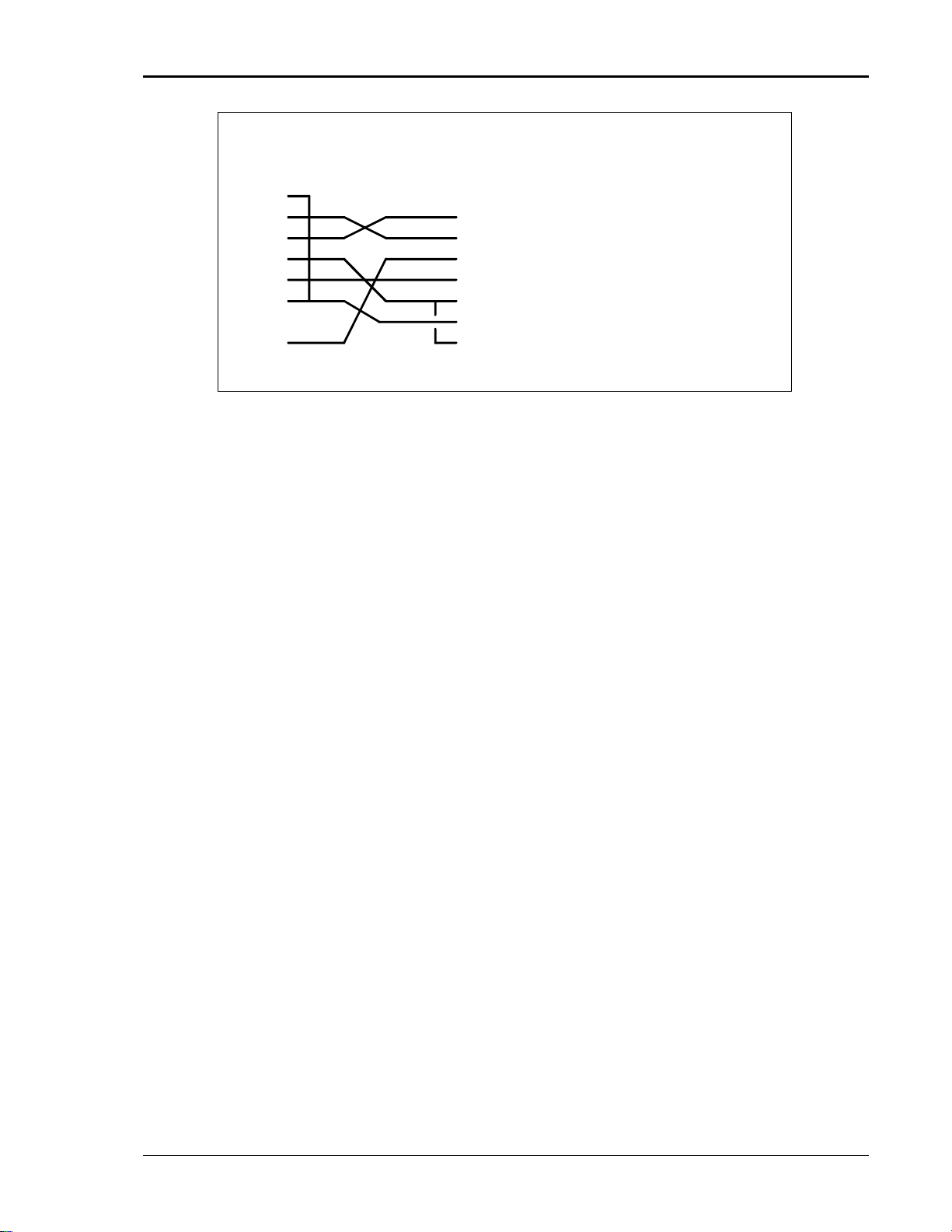
User Manual – Rev M California Instruments
DB-9 PC
DB-9 AC Source
Pin
1
2
3
4
5
6
7
8
9
Pin
1
2
3
4
5
6
7
8
9
Direction
output
input
output
output
input
-
output
Description
reserved
Receive data(RxD)
Transmit data (TxD)
Data Terminal Ready (DTR)
Signal Ground
Data Set Ready (DSR)
no connect
no connect
reserved
Figure 3-12: RS232C Cable for PC Connection wiring diagram – MX without USB.
MX15 53
Page 54

User Manual – Rev M California Instruments
Pin
Name
Description
1
VBUS
+5 VDC 2 D-
Data - 3 D+
Data + 4 GND
Ground
3.7.6 USB Interface
A standard USB Series B device connector is located on the rear panel for remote control. A
standard USB cable between the AC Source and a PC or USB Hub may be used.
Note: Use of the USB port to control more than one power source from a single PC is
not recommended, as communication may not be reliable. Use GPIB interface for
multiple power source control.
Figure 3-13: USB Connector pin orientation.
Table 3-9: USB Connector pin out.
MX15 54
Page 55

User Manual – Rev M California Instruments
Pin
Ethernet TPE
10BaseT/100BastT/1000BaseT
EIA/TIA 568A
EIA/TIA 568B
Crossover
1
Transmit/Receive Data 0 +
White with green stripe
White with orange stripe
2
Transmit/Receive Data 0 -
Green with white stripe or
solid green
Orange with white stripe or
solid orange
3
Transmit/Receive Data 1 +
White with orange stripe
White with green stripe
4
Transmit/Receive Data 2 +
Blue with white stripe or
solid blue
Blue with white stripe or
solid blue
5
Transmit/Receive Data 2 -
White with blue stripe
White with blue stripe
6
Transmit/Receive Data 1 -
Orange with white stripe
or solid orange
Green with white stripe or
solid
7
Transmit/Receive Data 3 +
White with brown stripe or
solid brown
White with brown stripe or
solid brown
8
Transmit/Receive Data 3 -
Brown with white stripe or
solid brown.
Brown with white stripe or
solid brown
3.7.7 LAN Interface – RJ45
An optional RJ45 Ethernet 10BaseT connector is located on the rear panel for remote control. A
standard RJ45 UTP patch cord between the AC Source and a network Hub may be used to
connect the AC source to a LAN. For direct connection to a PC LAN card, a crossover RJ45
cable is required. Consult your network administrator for directions on connecting the AC source
to any corporate LAN.
If the –LAN Ethernet interface option is present, the MAC Address (Media Access Control) of the
Ethernet port is printed on the serial tag of the power source. The serial tag is located on the rear
panel of the unit.
For information on how to set up a network connection or a direct PC connection using the LAN
interface, refer to the MX Series Programming Manual P/N 7003-961 distributed in Adobe PDF
format on CD ROM CIC496.
LAN
Table 3-10: RJ45 LAN Connector pin out.
MX15 55
Page 56

User Manual – Rev M California Instruments
Top View from
back of MX15
Chassis
3.8 Multiple Cabinet System Configurations (incl. –MB)
Multi-cabinet MX models consist of two or three autonomous or Auxiliary MX15-1Pi units.
Auxiliary units do not have their own controller and are identified easily by their blank front panel.
Master units each have their own controller but can be configured as auxiliary units by
disconnecting the ribbon cable marked J17 between the controller and the system interface
board (P/N 7005-701-1). This disables the controller and allows the MX15 to operate as an
Auxiliary unit. (Requires removal of the top cover)
When used as a multi-cabinet system for higher power applications, the controllers in the unit(s)
acting as the auxiliary to the master are either disabled or not present.
In addition to disabling the controller if present (as described above), the DIP switch (S1), located
on the GPIB / RS232C / IO assembly in the auxiliary cabinets, settings need to be changed.
(Requires removal of the top cover). The correct switch settings are shown below. (shown set for
Master cabinet). Note that all units must be powered down before reconfiguring. Also, the output
wiring must be changed to accommodate the new configuration.
Note: If the units being re-configured for multi-cabinet operation were not factory
configured this way, it may be necessary to balance the amplifiers by adjusting
their gain. Refer to section 6.4 for details on Amplifier balancing.
When used as a multi-cabinet system, the system interface cables must be connected between
the master and the auxiliary cabinets.
Figure 3-14: Multi-Cabinet DIP Switch Location and Setting
MX15 56
Page 57

User Manual – Rev M California Instruments
3.9 Multiple Cabinet Power Up/Down Procedures
For all multi-cabinet MX Series configurations (MX30/2, and MX45/3), the following Power Up
(Turn on) and Power Down (Turn off) procedures should be observed.
3.9.1 Power Up Procedure
Follow these steps:
1. Turn on each of the Auxiliary units using the front panel circuit breaker, one at a time.
The exact order for turning on the auxiliary units is not important. Note that the bias
supplies of each of the auxiliary cabinets will power up but not the actual amplifiers. This
is because the auxiliary units are waiting for the turn on signal from the master unit.
2. Once all auxiliary units are on, turn on the MASTER unit LAST using the front panel
circuit breaker. The master unit will go through an initialization process and power up
itself plus the auxiliary units.
3. Allow 20 to 30 seconds for the turn on sequence to complete before attempting to
communicate with the system.
3.9.2 Power Down Procedure
The power-down / shutdown sequence for the system is the reverse of the power-up / turn-on
sequence. This means the MASTER unit is turned off FIRST. Once the MASTER shuts down,
all auxiliary units’ main AC input power contactors will open up automatically. They still need to
be turned off individually using the front panel circuit breaker. This will shut down their bias
supplies as well.
Follow these steps:
1. Disconnect the EUT by opening the MX15 output relay. Use the Output On/Off button on
the master unit front panel or send the “OUTPUT 0” command over the bus to do so.
2. Turn off the MASTER unit FIRST using the front panel circuit breaker. The master unit
will disengage the main AC power input contactors of all auxiliary units at this time.
3. Next, turn off each of the Auxiliary units using the front panel circuit breaker, one at a
time. The exact order for turning off the auxiliary units is not important.
MX15 57
Page 58
User Manual – Rev M California Instruments
CONFIGURATION
Field
Parameter
Description
CLOCK/LOCK
N/A
Clock and Lock option is disabled
ON
Clock and Lock option is enabled and can be
turned on in the MODE field of the CONTROL
menu.
3.10 Clock and Lock Configurations
The MX15 Series may optionally be equipped for clock and lock mode of operation. This mode is
a special form of Master/Auxiliary, which requires each chassis to have its controller. As such, it
is possible to create 1, 2, or 3 phase power systems using 2 to 3 MX15 chassis. For most singlephase configurations, the normal multi-box mode of operation as described in section 3.7.5 is
recommended as it provides a single controller (and remote control interface).
In a clock and lock configuration, each unit has its own front panel controls (as well as individual
remote control interfaces) for operating the supply but the output frequency of the auxiliary unit(s)
(-LKS option) is synchronized (locked) to the Master MX unit (-LKM).
This mode of operation requires that one MX15 has the -LKM (Lock Master) option and one or
two MX units have the -LKS (Lock auxiliary) option.
3.10.1 Clock/Lock Configuration Settings
Clock and lock configuration settings for -LKM and -LKS equipped MX15's are set at the factory
at the time of shipment and cannot be changed. To check the configuration settings for an MX15,
select the OPTIONS screen. In the options screen, the CLOCK/LOCK entry determines if the unit
can be set as a Master or Auxiliary as follows:
Note that the actual mode of operation of a Clock/Lock MX15-LKS auxiliary unit is determined by
the Clock mode set in the CONTROL menu. For clock and lock mode of operation, the CLOCK
field is set to EXT.
MX15 58
Table 3-11: Clock and Lock Configuration settings
Page 59

User Manual – Rev M California Instruments
INITIAL SETUP 3
Field
Parameter
Description
CLK/LOC
STAN
Normal stand alone mode of operation. For
standard MX15 power source with no clock
and lock mode of operation.
MAST
For master (-LKM) power source in clock and
lock mode of operation.
AUX
For auxiliary (-LKS) power source in clock and
lock mode of operation. Powers up with clock
mode set to external.
3.10.2 Clock/Lock Initialization Settings
The mode of operation of the MX15 is determined by the MODE setting in the CONTROL menu.
If the clock and lock option is enabled, three choices will be available for this field: STAN, MAST,
and AUX. Changing the MODE to either MAST or AUX will cause the power source to power on
in clock and lock mode.
Available initial settings and their relationship to the Clock and Lock mode of operation are
shown in the table below.
Table 3-12: Clock and Lock Initialization settings
3.10.3 Clock/Lock and External Sync Mode
Note that an MX15-LKS auxiliary unit is factory configured to operate in Clock and Lock mode
when EXT clock mode is selected. This means that an MX15-LKS cannot be used in normal
external sync mode. However, the MX15-LKM master unit can be operated in external sync
mode.
Furthermore, since the MX15-LKM master unit is factory set for Master mode of operation, it in
turn cannot be used as an Auxiliary source in a clock and lock configuration.
Note: When the clock and lock option is enabled, each power source will have all three settings
available in the MODE field. The master box must be set to either STAN or MAST and the
auxiliary box must be set to either STAN or AUX or the clock and lock feature will not work
correctly.
3.10.4 Remote Programming of Clock and Lock systems
Since clock and lock systems have multiple autonomous controllers that are synchronized in
frequency, remote programming of these systems requires that the application program deal with
all MX controllers. This often precludes the use of RS232C as generally not enough serial ports
are available. The use of GPIB instead also offers the advantage of using the Group Execute
Trigger (GET) capability to effect output changes on all phases (MX's) simultaneously which is
otherwise difficult to do.
To set up a GPIB remote controlled clock and lock systems, the GPIB addresses for the
individual MX's must be set to different address values in the CONFIGURATION menu.
MX15 59
Page 60

User Manual – Rev M California Instruments
Note: This mode of operation is not supported by the MXGUI Windows software
supplied with each MX15 unit.
MX15 60
Page 61

User Manual – Rev M California Instruments
3.11 Basic Initial Functional Test
CAUTION: Work carefully when performing these tests; hazardous voltages
are present on the input and output during this test.
Refer to Figure 3-15 for the required functional test set up. Proceed as follows to perform a basic
function check of the power system:
1. Verify the correct AC line input rating on the nameplate of the MX unit(s) and make sure the
correct three-phase line voltage is wired to the input of the MX before applying input power.
2. Connect a suitable resistive or other type load to the output of the MX. The load resistance
value will depend on the voltage range you plan to check. Make sure the power resistor has
sufficient power dissipation capability - up to 15 KW for full load test.
3. Connect an oscilloscope and DMM / voltmeter to the AC source output. Set both for AC
mode.
4. If the correct voltage is present, turn on the MX unit(s) by closing the On/Off circuit breaker
on the front panel. For multi-cabinet systems, turn on the auxiliary unit first and wait for them
to cycle on, then turn on the master unit.
5. Set the output voltage to 0 volt and close the output relay with the OUTPUT ON/OFF button.
There should be little or no output although the DMM may show a noise level, especially if
the DMM is in auto ranging mode.
6. Move the cursor to the VOLTAGE field in the PROGRAM 1 screen and either use the
keyboard to program a small voltage (20 VAC) or slew the voltage up slowly with the knob.
Observe the DMM reading. The reading should track the programmed voltage.
7. Also monitor the scope. The output should be a sinusoidal voltage waveform.
8. If the output tracks, increase the voltage until you reach 80 % of the voltage range or more.
Check the output voltage reading and waveform.
9. Select the MEASUREMENT screen by pressing the MEAS button. The output voltage,
current and power will be displayed.
In the unlikely event the power source does not pass the functional test, refer to the calibration
procedure in Section 6 or call California Instrument’s customer satisfaction department for further
assistance.
MX15 61
Page 62
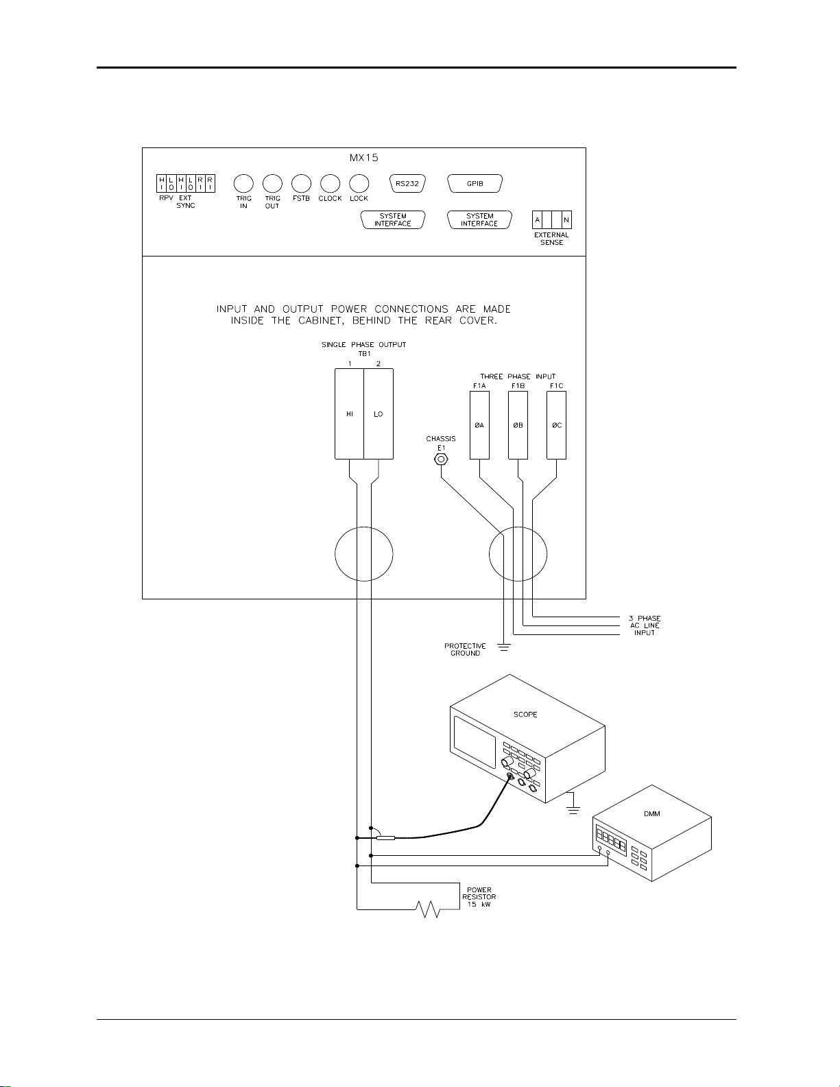
User Manual – Rev M California Instruments
Figure 3-15: Functional Test Setup.
MX15 62
Page 63

User Manual – Rev M California Instruments
3.12 Remote Inhibit / Remote Shutdown
It may be necessary to provide a remote shutdown of the AC or DC output of the MX. The
external remote inhibit input may be used for this purpose (RI). This input is also referred to as
remote shutdown.
The default mode of operation for the RI input is a contact closure between pins 5 and 6 (return)
of the rear panel screw-terminal strip. This will open the output relay of the MX. The same can be
accomplished with an active low TTL input signal.
It is possible to reverse the polarity of the RI input. This requires the use of the following bus
command:
OUTPut:RI[:LEVel] HIGH /* Sets RI polarity to active high.
OUTPut:RI[:LEVel] LOW /* Sets RI polarity to active low (Factory default)
Either the RS232, USB, LAN or GPIB interface must be used to perform this setting. Once set,
the polarity setting remains in effect.
When set to HIGH, an active low TTL level or a contact closure is required to enable the output
relay of the MX. Opening the contact or removing the low input signal will cause the output relay
to open.
MX15 63
Page 64

User Manual – Rev M California Instruments
3.13 Junction Box Accessory
An optional wiring junction box (P/N 7003-416-1) is available which may be used to connect the
outputs of 2 to 6 MX cabinets together. The junction box also has a protective ground
connection, which MUST be connected to a suitable protective earth ground.
Each junction box has four sets of terminals for phase A, phase B, phase C and Neutral. For
MX15 application, only phase A and Neutral connections will be made. Each terminal is lined up
with a strain relief on each side. The outputs from the MX15 cabinets connect to the “MX
SYSTEM OUTPUT” side of these terminal blocks. The load can be connected to the “LOAD”.
Note that the wiring is not supplied with the system and must be provided by the end user. The
wire gauge of the load connection must be sized to handle the maximum current in the low
voltage range of operation.
The “MX SYSTEM OUTPUT” side of the terminal block will accept up to 8 wires. If the external
sense connection is made at the junction box, one of these can be used to connect the sense
wiring.
Note: Do not swap output load wires or sense wires between phases, as damage to the system
will result.
The “LOAD” side will accept 2 wires. The wire size range shown in Figure 3-16 refers to
mechanical compatibility of terminal block only. This information does not reflect required wire
size.
The wire sizes accepted by the terminal blocks of the junction box on each side are shown in
Figure 3-16.
Figure 3-16: 7003-416-1 Output Junction Box
MX15 64
Page 65

User Manual – Rev M California Instruments
To MX15
Output
3.14 Output Filter Box Accessory
An optional output filter box (P/N 7003-424-1) is available which may be used reduce the amount
of ripple and noise present at the output of the MX15-3Pi.
The filter must be connected between the single-phase output of the MX15 and the unit under
test. To access the connection terminal blocks, the top cover of the filter case must be removed.
Note: Make sure all power is off when connecting the filter accessory.
The output of the MX15 is connected to the input side of the filter. Use terminal blocks TB1A
(phases A and B) and TB1B (phase C and neutral) as indicated in Figure 3-17. For MX15
application, only phase A and Neutral connection will be made. The load can be connected to
the load side of the filter box using terminal blocks TB2A and TB2B. Do not swap phases through
the filter.
To compensate for voltage drop across the filter, the external sense connections can be made at
the load (load side of the filter).
Note: The filter box chassis must be connected to earth ground.
It is not recommended to use the ground connection on the MX15 itself for this purpose but
rather a ground point at the AC service to the MX15.
Figure 3-17: 7003-424-1 Output noise filter box.
MX15 65
Page 66

User Manual – Rev M California Instruments
4 Front Panel Operation
4.1 Tour of the Front Panel
The MX Series with type P or type Pi have identical front panels although some of the keys found
on the front panel are only used by MX models with the Pi controller. If your unit is a P type
controller, these keys will act as don’t cares. This chapter provides information on operating the
MX with either controller type.
Before operating the AC source using the front panel, it helps to understand the operation of the
front panel controls. Specifically, the operation of the knob, keyboard and the menu layout are
covered in the next few paragraphs.
4.1.1 Front Panel Controls and Indicators
The front panel can be divided in a small number of functional areas:
Mains circuit breaker
Status Indicator lights
Shuttle knob
LCD display
FUNCTION keypad
DATA ENTRY keypad
4.1.2 System On/Off Circuit Breaker
The circuit breaker located on the left side of the front panel disconnects the low voltage supply
of the MX Source from the three phase Line input. This will remove power from the mains AC
input contactor and thus remove input power from the MX Series power source. As such, the
circuit breaker acts as an indirect power on/off switch for the MX Series unit. Note however that
an AC input power remains applied to the primary side of the input transformer.
When the input current rating of the MX Series AC power source is exceeded, the protective
fuses (XF1 through XF3) will blow. In this case, power to the low voltage supply may still remain
through the front panel circuit breaker. In this case, the on/off circuit breaker should be opened
(power off) first followed by a complete disconnect of all ac input power through an installed main
circuit breaker.
Note that in MX30/2 and MX45/3 systems, each unit has its own on/off circuit breaker and set of
line input fuses.
MX15 66
Page 67

User Manual – Rev M California Instruments
4.1.3 Status Indicator Lights
Five LED status indicators are located to the left of the LCD display. These LED’s correspond to
the following conditions:
REMOTE The REMOTE LED indicates that the unit is in remote control
mode. If the IEEE-488 interface is used, this indicator will be lit
whenever the REM line (REMOTE ENABLE) line is asserted by
the IEEE controller. If the RS232, USB or LAN interface is used,
the REMOTE state can be enabled by the controller using the
SYST:REM command. Any time the REMOTE LED is lit, the
front panel of the MX Series unit is disabled. The BACK key
doubles as a LOCAL button that allows the user to regain
control of the front panel.
OVERLOAD The OVERLOAD LED indicates an output overload condition.
This condition can be controlled by setting the current limit value
in the PROGRAM menu. Removing the load using the OUTPUT
ON/OFF button will recover from an overload condition.
OVER TEMPERATURE The OVER TEMPERATURE LED indicates an overheating
problem inside the unit. This is an abnormal condition, which will
cause the unit to shut off. Check the air openings to make sure
they are not blocked.
HI RANGE The HI RANGE LED is on when the high voltage output range
has been selected.
OUTPUT The OUTPUT LED is on when the output relay is closed.
MX15 67
Page 68

User Manual – Rev M California Instruments
4.1.4 The Shuttle Knob
Figure 4-1: Shuttle Knob
The shuttle knob is located to the right of the keypad and is used to change setup parameters.
Note that it cannot be used to move the cursor position between menu fields. Use the UP and
DOWN arrow keys in the FUNCTION keypad for this.
The shuttle knob can operate in one of two distinct modes of operation:
MODE DESCRIPTION
IMMEDIATE mode Any time the ENTER key is pressed, the MX Series returns to its
normal mode of operation. In this mode, changes made with the
shuttle knob or the data entry keypad will take immediate effect.
The IMMEDIATE mode is useful for slewing output values such
as voltage and frequency and observing the effect on the load.
SET mode When the SET key located in the FUNCTION keypad is
pressed, changes made with the shuttle to any output parameter
will not take effect until the ENTER key is pressed. In this mode,
any changes made to a setup menu will be blinking to indicate
the pending change condition. This mode allows changes to be
made to all output parameters and executing them all at once by
pressing the ENTER key.
MX15 68
Page 69

User Manual – Rev M California Instruments
4.1.5 FUNCTION Keypad
The function keypad provides access to all menus and measurement screens. The following
keys are located in the FUNCTION keypad:
Figure 4-2: FUNCTION Keypad
KEY DESCRIPTION
ON/OFF The ON/OFF key may be used to control the state of the output
relay. The active state is indicated by the Output LED. If the
output relays are open (LED is off), the output is floating.
PHASE The PHASE key has no function and is a don’t care.
SET The SET key selects the PROGRAM setting screen. While this
screen is displayed, the rotary knob can be used to change
either voltage or frequency. Additional output settings such as
current limit can be reached by using the down cursor key. If
the PROGRAM screen is already displayed, the SET key puts
the unit in SET mode. For test options such as –704 or –160,
the SET key can be used to skip to the next test in a test
sequence during test execution.
MEAS The MEAS key selects the measurement screen. There are no
user changeable fields in the measurement screen. The rotary
knob is active while the measurement screen is displayed.
Additional measurement data can be displayed by using the up
and down cursor keys.
MENU The top-level menu is accessed by pressing the MENU key.
Refer to section 4.2 for details on available menus. If a menu
screen is already displayed, the MENU key will advance to the
next menu.
BACK The BACK key may be used to back up to the previous menu
level or previously selected screen. It can also be used as a
backspace key to delete the last digit entered.
For tests options such as the –160 and –704 options, the BACK
key can be used to abort a test in progress.
If the unit is in remote mode, (Remote LED is lit), the front panel
of the power source is disabled. The BACK button doubles as a
GOTO LOCAL button (LOCAL) while the unit is in remote state.
This allows the user to regain control of the front panel. This
LOCAL button can be disabled by sending a Local Lockout bus
command. This prevents unauthorized changes of settings in
ATE applications.
MX15 69
Page 70

User Manual – Rev M California Instruments
4.1.6 Cursor and Enter Keys
The cursor keys are located on the right hand side of the numeric keypad and can be used to
scroll through a list of menu entries:
CURSOR UP () The UP key moves the cursor position upwards one position to
the previous available cursor position.
CURSOR DOWN () The DOWN key moves the cursor position downwards one
position to the next available cursor position.
ENTER The blue Enter key is used to confirm selections made in
menus or to active settings made in SET mode.
4.1.7 LCD Display
The LCD display of the power source provides information on instrument settings and also
guides the user through the various menus. A sample of the measurement display screen is
shown in Figure 4-3.
Menus are accessed by scrolling through two or more entries. Alternatively, the Menu key may
be pressed repeatedly to access additional available menu entries.
The active cursor position is indicated by a LEFT POINTING ARROW () and can be moved by
using the UP ()and DOWN () keys located on the right hand side of the numeric keypad.
Figure 4-3: Measurement Screen
MX15 70
Page 71
User Manual – Rev M California Instruments
4.2 Menu Structure
The next few pages show a map of the available menus in the MX15 Series. All menus can be
reached by repeatedly pressing the MENU key. Frequently used menus have a short cut key that
provides direct access. Examples of such menus are Program and Measurements. In any case,
there are never more than two levels of menus although some menus may be spread across
more than one screen.
4.2.1 Power on screens
At initial power up, the MX15 Series power supply will display important configuration information
in a series of power on screens. These displays are only visible for a short period of time and will
not re-appear until the next time the unit is turned on.
There are four screens that will appear in the same order:
1. LANetwork detection... At power up, the unit will try to detect a LAN interface. If not found, a
“LAN not available” message will appear. The LAN will not be detected if:
1. No –LAN option is installed.
2. The USB port is connected to a computer.
3. The RS232 port jumper is installed.
This process may take several seconds.
2. Initialization in progress. This means the firmware has started to load.
3. Company and firmware information. Displays the manufacturer - Cal Inst., which is short for
California Instruments - and the firmware part number and revision. The firmware part
number starts with CIC followed by a three-digit code and dash number. The firmware
revision has a major revision before the decimal point and a minor revision after the decimal
point.
4. Model and Serial number information. The model will be a function of the configuration and
will include the series designation (MX). The serial number is a 5-digit number. This number
should match the model type sticker located on the back of the unit.
5. Memory test result. If all memory tests pass at power on, the message "Self test passed" will
appear. If not, an error message will be displayed instead. This information may be useful
when calling in for service support.
MX15 71
Page 72

User Manual – Rev M California Instruments
ENTRY
DESCRIPTION
PROGRAM
The PROGRAM menu allows primary output parameters such as
voltage, frequency, current limit, waveform shape and voltage
range to be changed.
CONTROL
The CONTROL menu allows secondary setting parameters such
as sense mode, phase mode and ALC mode to be changed.
MEASUREMENTS
The MEASUREMENT screen is not a menu in that no user entries
are required. It displays read-back data.
TRANSIENTS
The TRANSIENTS menu allows output transients to be
programmed.
REGISTERS
The SETUP REGISTERS menu allows complete instrument
settings and transient list programs to be saved to nonvolatile
memory.
CONFIGURATION
The CONFIGURATION menu allows changes to be made to
configuration settings such as the IEEE-488 address, RS232C
internal baud rate, and power on state.
OUTPUT CAL
The OUTPUT CAL menu provides access to the LCD viewing
angle and Calibration password entry. If the correct calibration
password is entered, additional calibration screens can be
accessed.
MEAS CAL
The MEAS CAL menu allows for calibration of the AC source
measurement system.
APPLICATIONS
The APPLICATIONS menu provides access to the optional
firmware application programs that may be installed in the power
source controller.
OPTIONS
The OPTIONS menu provides access to optional functions that
may be present on the power source.
Once the power on sequence is completed, the power source will always revert to the
PROGRAM screen shown here. The power source is now ready to be used.
4.2.2 Top Level Menus
The following top-level menu choices can be accessed using the Menu key:
MX15 72
Page 73

User Manual – Rev M California Instruments
ETIME/TEMP
The ETIME/TEMP screen displays the Elapsed time (Time the unit
has been in operation) in hours, minutes and seconds. It also
displays the internal temperature of the unit in degrees Celsius.
LIMITS
The LIMITS screen displays the hardware configuration limits of
the AC power source. It is for display purposes only and the user
can change none of these fields.
MX15 73
Page 74
User Manual – Rev M California Instruments
MX15 Series
Menu Structure
LEVEL 1
LEVEL 2
LEVEL 1
LEVEL 2
PROGRAM
VOLT 120.0V
REGISTERS
SAVE REG #
CONTROL
FREQ 400.0HZ
CONFIGURATION
RECALL REG #
VRANGE 150.0V
ADDRESS 1
PHASE 0.0°
BAUD RATE 38400
FUNC >SINUSOID
PON STATE RST
CLIP THD 10.0
LANetwork <
VOLT MODE AC
OUTP CAL
VIEW ANGLE 0
DC OFFSET N/A
MEAS CAL
CAL PWORD 0
CURR 125.00A
VOLT FS 17251
OL MODE CV
VOLT ZERO -91
SENSE INT
IMP REAL FS 0
SYNC INT
IMP REAC FS 0
CLOCK INT
IMP REAL0in
MODE STAN
IMP REAC0in
ALC STATE ON
PHASE OFST 0.0
IMP STATE OFF
IMP RES 0mΩ
VIEW ANGLE 0
IND 0mH
CAL PWORD 0
# OUTPUTS N/A
MVOLT FS -1000
ST PHASE RAND
MCURR FS -3000
MEASUREMENT
100.00V 49.04A
APPLICATIONS
MIL704
TRANSIENT
400.0HZ 4.9KW
OPTIONS
DO160
4.9KVA 1.00pF
MS704
49.04A 0.98cF
WHM
0.18%A 0.05A
REGEN
0.19%V 0.0°
INTER HARMONICS
TRAN ST IDLE
SYSTEM MX15-1Pi
COUNT 10
ADVANCE ON
TRIG SOUR IMM
MODE N/A
TRAN STEP AUTO
CLOCK/LOC N/A
VOLT #12 120.0
MIL704 N/A
VSLEW #12 MAX
DO160 N/A
FREQ #12 400.0
MS704 N/A
FSLEW #12 10.00
ABD N/A
4.2.3 Menu Tree
MX15 74
Page 75
User Manual – Rev M California Instruments
DWELL #12 10.00
LF N/A
TTLT #12 ON
MB N/A
FUNC #12 SINUSO
WHM N/A
PHASE#12 0.0
LAN N/A
CURR #12 125.0
OPT(0) N/A
SNK N/A
IEC413 N/A
Power On
IEC411 N/A
Screens
#1
Initialization
ETIME/TEMP
ETIME 21:20:03
in progress
LIMITS
TEMP 25:33°C
#2
CAL. INST.
LIM VOLT
CIC920-1,Rev 1.0
LOW 150.0
#3
MODEL MX15-1Pi
LIM VOLT
SERIAL #54321
HIGH 300.0
#4
Memory test
LIM VOLT
passed
Xform 400.0
LIM FREQ
LOW 16
LIM FREQ
HIGH 819
LIM CURR 125.0
PHASE(C) 0.0
Table 4-1: Menu Tree
MX15 75
Page 76
User Manual – Rev M California Instruments
ENTRY
DESCRIPTION
VOLT
Programs the output voltage in Vrms. The voltage can be
changed from 0 to its max range value as determined by the
configuration settings and the selected voltage range by using
the keypad + Enter or the shuttle (if the voltage field is selected).
FREQ
Programs the output frequency. The frequency can be changed
from its min to its max value as determined by the configuration
settings by using the keypad + Enter or the shuttle (if the
frequency field is selected).
VRANGE
Selects 150V, 300V, or 400V voltage range (if available). The
value of this field can be changed with the shuttle as long as the
active pointer () points to the VRANGE entry.
PHASE
Selects the phase angle between the external clock and the
output of the AC source. If the clock source is internal, this
parameter has no effect.
FUNC
Selects the waveform for the selected phase. On MX15-1Pi
models, available choices are SINUSOID, SQUARE and
CLIPPED or any user defined waveform that was downloaded to
the AC source waveform memory using the RS232 or IEEE-488
interface.
This field is fixed to SINUSOID on MX15-1 models.
CLIP LEVEL
Sets the clip level for the CLIPPED sine wave in percent VTHD.
4.2.4 PROGRAM Menus
Figure 4-4: PROGRAM Menus
The PROGRAM menu is shown in Figure 4-4. It can be reached in one of two ways:
1. By selecting the MENU key, selecting the PROGRAM entry and pressing the Enter key.
2. By pressing the SET key.
The PROGRAM menu is used to change primary output parameters. Less frequently used
parameters are located in the CONTROL menu.
The following choices are available in the PROGRAM menus:
MX15 76
Page 77

User Manual – Rev M California Instruments
ENTRY
DESCRIPTION
The range is 0 to 20 %. (MX15-1Pi models only).
Note: Changing the clip level setting will result in temporary loss
of the output voltage as the new clipped waveform is loaded.
This may cause the EUT to reset or turn off. To avoid this, set
the desired clip level before programming the AC voltage and
turning on the output to the EUT or use the transient list system
to switch between waveforms.
VOLT MODE
Selects the available output modes of operation. Available
modes are AC, DC (all models) and ACDC (Pi models only). The
shuttle can be used to select the desired output mode.
DC OFFSET
This parameter applies only when the power source is in ACDC
mode. The DC offset can only be set to a max value of
220VDC. The rms level of the AC+DC waveform may not
exceed the limit of the voltage range (150V or 300V).
Note: Changing the offset percentage setting will result in
temporary loss of the output voltage as the new offset is loaded.
This may cause the EUT to reset or turn off. To avoid this, set
the desired offset percentage before programming the AC
voltage and turning on the output to the EUT.
CURR
Sets the current limit value for the current detection system.
When the load current value exceeds the set current limit, a fault
condition is generated. The actual response of the AC Source to
a current limit fault is determined by the protection mode
selected in the OL MODE field. (CC = Constant Current, CV =
Constant Voltage).
OL MODE
Sets the current limit overload mode. The actual response of the
AC Source to a current limit fault is determined by this setting.
Available settings are CC for Constant Current mode or CV for
Constant Voltage mode. In CV mode, the AC source output will
trip off and stay off until re-engaged. In CC mode, the voltage will
be reduced until the current limit is no longer exceeded.
MX15 77
Page 78
User Manual – Rev M California Instruments
ENTRY
DESCRIPTION
SENSE
Selects internal or external (remote) voltage sense mode. If INT is
selected, the voltage is sensed at the output terminal block. If EXT is
selected, the voltage is sensed at the external sense connector. If
external sense is selected, care must be taken to connect the
external sense lines at the load. For sense leads longer than 1
meter, twisted pairs should be used.
SYNC
Selects the external sync mode if available. Default is internal sync,
which means a free running time base. The time base can be
synchronized to an external sync signal by selecting external sync
mode.
CLOCK
Selects internal or external clock source. The MX Series controller
uses an open-air crystal time base with an accuracy of 100 ppm. The
external clock mode is used to support the –LKS option. For use as
an auxiliary unit in a clock and lock system, this field must be set to
EXT. A unit with –LKS option can be used stand-alone if needed by
setting the INT clock mode.
INT
Default, internal clock.
EXT
Auxiliary unit (-LKS) driven by master (-LKM) clock
input.
Note: When selecting EXT mode, make sure the
Clock and Lock BNC cables are connected to the
Master (-LKM) unit. If not, there will be no output on
the –LKS unit. See section 3.10 for connection
information.
4.2.5 CONTROL Menus
Figure 4-5: CONTROL Menus
The CONTROL menu is shown in Figure 4-5 and can be reached by selecting the Menu key,
selecting the CONTROL entry using the DOWN cursor key and then pressing the Enter key.
The CONTROL menu is used to change secondary output parameters. The following choices are
available in the CONTROL menus:
MX15 78
Page 79
User Manual – Rev M California Instruments
ENTRY
DESCRIPTION
MODE
Power on clock mode. The following two modes can be selected.
STAN
Power up in INT (internal) clock mode for standalone operation. This is the only mode for models
without the –LKS option.
For units with the –LKM option installed, this field is
fixed to CLK/LOCK.
For units with the –LKS option installed, this field can
be changed to CLK/LOCK for use as an auxiliary
unit in a clock and lock system or to STAND for use
as a stand alone unit.
CLK/LOCK
Fixed on master (-LKM) unit configuration in a clock
and lock system. Power up with EXT (external) clock
mode on unit with –LKS option. (See OPTION menu
section.).
Note that this field cannot be changed if the –LKM
option is installed.
The frequency resolution below 81.9 Hz in MAST
clock and lock mode is reduced to 0.1 Hz from the
normal 0.01 Hz.
ALC STATE
Sets the Auto Level Control (ALC) mode. This mode uses the
internal measurement system to zero regulate the output. There are
three modes of operation:
OFF No measurement based output regulation.
REG Output regulation is enabled. AC source will continuously
regulate output but will not trip off output.
ON Output regulation is enabled and output will fault (trip off)
with Error 801 “Output Voltage fault” if regulation cannot be
maintained and the programmed output voltage is 10Vrms or
higher. No error is generated for settings below 10 volt.
In most situations, the ALC mode should be set to REG or ON for
optimal performance.
Note: The ALC mode only functions for programmed output voltages
above 10 Vrms.
IMP STATE
Selects programmable output impedance. The ALC mode must be
turned off for the programmable impedance to be turned on. This
function allows you to change the output impedance (R and/or L) of
the power source.
# OUTPUTS
Selects SINGLE or THREE phase mode of operation. The MX15
models operate only in single-phase mode so this field will always
show N/A (not applicable).
MX15 79
Page 80

User Manual – Rev M California Instruments
ENTRY
DESCRIPTION
ST PHASE
Selects the start phase angle for output changes made to either
voltage or frequency. This allows changing the output at a specific
phase angle. The ON/OFF key also uses this phase angle setting to
program the output voltage up to the set level after the output relay is
closed. The default value for this field is RAND. To set the start
phase angle, set the cursor to the ST PHASE field and use either
shuttle knob or the keypad to adjust between ± 360°. To set to
RAND, use the BACK key.
MX15 80
Page 81

User Manual – Rev M California Instruments
ENTRY
DESCRIPTION
MEASUREMENTS 1
VOLTAGE
This value is the true rms output voltage measured at the voltage
sense lines.
CURRENT
This value is the true rms output current drawn by the load.
FREQ
The output frequency is measured at the sense lines.
TRUE POWER
This value is the real power.
MEASUREMENTS 2
VA POWER
This value is the apparent power.
POWER FACTOR
This readout shows the power factor of the load.
PEAK CURRENT
This value is the instantaneous peak current. See also PEAK CURR
in MEASUREMENTS 3 screen.
CREST FACTOR
This readout displays the ratio between peak current and rms
current.
MEASUREMENTS 3 (iX Models only)
CURR THD
This readout displays the total current distortion for the selected
4.2.6 MEASUREMENTS Screens
The MX Series uses a DSP based data acquisition system to provide extensive information
regarding the output of the source. This data acquisition system digitizes the voltage and current
waveforms and calculates several parameters from this digitized data. The results of these
calculations are displayed in a series of measurement data screens. A total of three
measurement screens are used to display all this information.
Figure 4-6: MEASUREMENT Screen
The Measurement screens available on the MX15 Series are not menus in that no changes can
be made anywhere. Instead, these screens provide load parameter readouts. The measurement
screens can be reached by successively pressing the Meas key, which will toggle to all available
screens. Note that for -1 Series models, only the first two screens are available. For the –1Pi
series, all three measurement screens are available.
The following parameters are available in the measurement screens:
MX15 81
Page 82

User Manual – Rev M California Instruments
ENTRY
DESCRIPTION
phase. The distortion calculation is based on the H2 through H50
with the RMS current in the denominator. Note that some definitions
of THD use the fundamental component (H1) of the current as the
denominator.
If desired, the user can program the power source controller to use
the fundamental component as the denominator. This mode can only
be programmed over the bus by sending the “MEAS:THD:MODE
FUND” command. At power up or after a reset command, the mode
will revert back to RMS.
PEAK CURR
This readout reflects the highest peak current value detected at the
output. This is a track and hold peak current measurement. To
measure inrush current for a unit under test, open the output relay
and reset the peak current value using the BACK key. Then program
the output voltage and frequency and turn on the output relay. The
peak current measurement will continuously track the maximum
current value detected until reset. See also PEAK CURRENT in
MEASUREMENTS 2 screen.
VOLT THD
This readout displays the total voltage distortion for the selected
phase. The distortion calculation is based on the H2 through H50
with the RMS voltage in the denominator. Note that some definitions
of THD use the fundamental component (H1) of the voltage as the
denominator.
If desired, the user can program the power source controller to use
the fundamental component as the denominator. This mode can only
be programmed over the bus by sending the “MEAS:THD:MODE
FUND” command. At power up or after a reset command, the mode
will revert back to RMS.
PHASE
Relative voltage phase angle measurement with respect to phase A.
This readout is only relevant if an external clock source is used.
Update Program Functions from Measurement Screen
The Shuttle knob can be used to update voltage and/or frequency settings while the
measurement readout screen is displayed. To do so, select the desired parameter to be
changed while in the SET screen using the left arrow cursor. Then, select the measurement
screen by pressing the MEAS button. While the measurement screen is visible, the shuttle
continues to operate.
MX15 82
Page 83

User Manual – Rev M California Instruments
ENTRY
DESCRIPTION
TRAN ST
Indicates the status of the transient system. Available modes
of operation are:
IDLE
Transient system is in IDLE or inactive state. To
start a transient list, press the ENTER key while
on the TRAN STATE field. Note that the output
must be ON to run a transient program or an
error message will be displayed.
WTRIG
Transient system is armed and waiting for a
trigger event.
BUSY
Transient system is active. A transient list
execution is in progress.
COUNT
Sets the execution count for the transient system. A count of 1
indicates the transient will run 1 time. The count value can be
set with the shuttle or the keypad. The count range is from 1
through 2E+08. Values below 200,000 are displayed in fixed
point notation. Value higher than 200,000 are displayed as a
floating point number (2E+05). The display has insufficient
4.2.7 TRANSIENT Menu
The transient menu is used to program and execute user-defined output sequences. These
output sequences are defined as a sequential list of voltage and/or current settings that can be
executed in a time controlled manner.
Each step in these lists is assigned a sequence number ranging from #0 through #99. The
numbering determines the order in which each step is executed.
Each step can control the voltage setting, voltage slew rate, frequency setting, frequency slew
rate and dwell time. The dwell time determines how long the output dwells at the current step
before progressing to the next step. Dwell times can range from 1 ms up to 900000 seconds.
Transient lists can be set up from the front panel or over the bus. The transient list can be saved
with the rest of the front panel settings in one of the setup registers. (See Register Menu).
MX15 83
Page 84

User Manual – Rev M California Instruments
ENTRY
DESCRIPTION
characters to display the entire mantissa so entering values
above 2E+05 from the keyboard is not recommended.
TRIG SOURCE
Indicates the trigger source for transient system. Available
trigger sources are:
IMM
Immediate mode. The transient is started from
the front panel using the ENTER key.
BUS
Bus mode. The transient system is started by a
bus command or a group execute trigger (GET).
EXT
External mode. The transient system is started
by a user-provided external TTL trigger signal on
TRIGGER IN.
TRAN STEP
Indicates the transient system execution mode. Available
modes are:
AUTO
When triggered, the transient system will
automatically execute each list point sequentially
without waiting for a trigger between list points.
This execution is paced by the dwell time set for
each data point.
ONCE
When triggered, the transient system will
execute the first list point and wait for a new
trigger once the dwell time expires. This allows
triggered execution of each step in the transient
list.
List parameters:
VOLT
Step #
Voltage set point
VSLEW
Step #
Voltage slew rate in V/s
FREQ
Step #
Frequency set point
FSLEW
Step #
Frequency slew rate in Hz/s
DWELL
Step #
Dwell time in seconds.
Range is 0.001 to 900000
TTLT
Step #
ON: Generates an output trigger pulse at this
list step.
OFF: No output trigger.
The output trigger is available on the TRIG OUT
on the rear panel.
FUNC
Step #
Waveform selection. Available choices are
Sinusoid, Square, Clipped or any of the user
MX15 84
Page 85

User Manual – Rev M California Instruments
ENTRY
DESCRIPTION
provided waveforms in waveform memory (-1Pi
models only).
PHASE
Step #
Phase angle set point. (Not relevant for phase A
if clock mode is internal.)
CURR
Step #
Current set point
Transient List point data entry method.
Transient list points are numbered sequentially from 0 through 99 and executed in this order.
Each list point or list entry has 9 parameters as shown in the table above. To enter list point data,
the keypad must be used. The shuttle knob is used to increment or decrement the list point
sequence number (#). The sequence number can only be increased to the next available empty
(new) list point.
To move to the next or previous parameter, use the UP () or DOWN () cursor keys
It is not necessary to use all list points, only as many needed to accomplish the desired output
sequence.
Setting Data Values
Data values can be set for each point in a list. If all data values in a specific list are going to be
the same value (e.g. the current limit parameter is set to the same value for the entire transient
program), only the first data value for that parameter has to be set. Setting only the first data
point will automatically repeat that value for all subsequent points in the transient list.
Setting Slew Rates
Very often, output changes must be done as fast as the power source can make them. This
means the transient list slew rate is set to its maximum value. If this is the case for all the data
points in the list, it is sufficient to set just the first data point's slew rate for either voltage and/or
current. Setting only the first point of any parameter in the list will automatically cause all points
for that parameter to be set to the same value. This saves a lot of data entry time. The max slew
rate can be set by entering a value of 0. When the enter key is pressed, the value will change to
“MAX”.
If however, one or more data points require a specific slew rate such as needed to do a ramp, all
other points have to be specifically set to their required slew rates, including the maximum slew
rate.
Saving Transient Lists
Once completed, a transient sequence can be saved along with the steady state setup of the
instrument by using the REGISTER, SAVE menu. Registers that may be used for this purpose
are 1 through 15. It is advisable to do so, especially for longer transient lists.
MX15 85
Page 86

User Manual – Rev M California Instruments
ENTRY
DESCRIPTION
SAVE
REG 0 – 15
Saves the selected setup and transient list
from memory. (Setup only for Reg 0) The
shuttle knob may be used to scroll through the
available list of setup register numbers.
Use the ENTER key to perform the save
operation.
Register 0 can be assigned as the power-on
state setup from the CONFIGURATION menu.
A valid setup must be saved in REG0 to do so.
Note that REG0 only saves the setup, not the
transient list. All other registers also save the
transient list.
RECALL
REG 0 – 15
Recalls the selected setup and transient list to
memory. (Setup only for Reg 0) The shuttle
knob may be used to scroll through the
available list of setup register numbers.
Use the ENTER key to perform the recall
operation.
Register 0 can be assigned as the power-on
state setup from the CONFIGURATION menu.
A valid setup must be saved in REG0 to do so.
Note that REG0 only saves the setup, not the
transient list. All other registers also save the
transient list.
4.2.8 REGISTERS Menu
The registers menu provides access to the non-voltage setup storage of the power source. A
total of 16 front panel setups can be stored in registers numbered from 0 through 15. Each
register except register 0 can hold the complete front panel setup, including the programmed
transient list. This allows for quick recall of different setups and transient programs.
Register 0 is reserved to be used as the power-on setting as assigned by the user. To have the
power source start in a specific setting, save the desired setting to Register 0 and assign register
zero as the power-on default in the CONFIGURATION menu. Alternatively, the power source
can be set to power up with the RST factory default settings. See section 4.2.9 for factory default
settings.
MX15 86
Page 87

User Manual – Rev M California Instruments
ENTRY
DESCRIPTION
ADDRESS
0 - 31
Sets the selected IEEE / GPIB bus address for
the optional IEEE/GPIB interface.
Factory default is address 1. The shuttle knob
or the keypad can be used to set a value from
0 through 31. Do not use address 0 as this
address is typically reserved for the GPIB
controller.
BAUD RATE
9600
19200
38400
57600
115200
230400
460800
Sets the baud rate for the RS232
communications port. Factory default is
38400 baud. Available settings are 9600
through 115200 baud.
The same setting is used for USB and LAN
modes. For use with either USB or LAN, the
baud rate in this screen must be set to
460800.
Note: The shuttle knob can be used to scroll
through these selections.
PON STATE
REG0
RST
Determined power on state. This setting
selects either non-volatile REG0 to be recalled
automatically at power-on or factory default
(RST). Factory default is RST, which recalls
the factory settings. See below.
Factory default settings are:
Output relay Open
Voltage Range Low
Mode AC
Voltage 0 Vrms
Frequency 60 Hz
Note that to use REG0 for power-on default,
the contents of the register must be
programmed first. See section 4.2.8. If an
empty register is selected, the power source
will revert back to RST (factory setting).
4.2.9 CONFIGURATION Menu
The configuration menu may be used to configure various aspects of the instrument such as the
serial port (including USB and LAN), IEEE-488/GPIB address and the power-on settings of the
supply.
MX15 87
Page 88

User Manual – Rev M California Instruments
ENTRY
DESCRIPTION
LANetwork
LAN
If the –LAN option is installed; pressing Enter
while the cursor is on the LANetwork entry
provides access to the LAN interface setting
screens listed below.
IP Address
Displays the IP address setting. This value can
be changed by pressing the SET key and
entering a new value from the keypad. Use the
numeric data pad to enter each field. To move
between the four fields, use the decimal point
key on the keypad.
To set a fixed IP address, press SET and
enter the desired IP address. To set the unit to
DHCP mode, press SET and enter all zeros
(0.0.0.0) as the IP address and cycle power
two times. The obtained IP address will be
displayed after the second power on.
Any change to this value will NOT take effect
until after power on the unit has been cycled.
When changing mode from static IP to DHCP,
it is necessary to cycle power on the unit twice,
once to change mode and again to obtain and
display a new IP address from the network.
MAC Address
Displays the network Media Acces Control
address. This value is fixed and cannot be
changed. The same MAC is normally printed
on the model serial tag. The MAC address is
shown as six hexadecimal numbers separated
by a colon, e.g. 02:20:4A:9A:02:FD. Note that
the leading ‘0’ is never visible due to the
maximum number of LCD characters per line.
GWAddress
Gateway address setting. A default gateway
is a node (a router) on a computer network
that serves as an access point to another
network.
This value can be changed by pressing the
SET key and entering a new value from the
keypad. Use the numeric data pad to enter
each field. To move between the four fields,
use the decimal point key on the keypad.
Any change to this value will NOT take effect
until after power on the unit has been cycled.
HostBits
Number of host bits as opposed to network
bits in network mask. A CIDR class C network
uses 24 network bits and 8 host bits. (Class A
= 24, Class B = 16).
This value can be changed by pressing the
SET key and entering a new value from the
keypad. Any change to this value will NOT
take effect until after power on the unit has
MX15 88
Page 89

User Manual – Rev M California Instruments
ENTRY
DESCRIPTION
been cycled.
Port No
TCP remote port number. This value must be
set to 5025 (SCPI) to support the built in web
page.
This value can be changed by pressing the
SET key and entering a new value from the
keypad. Any change to this value will NOT
take effect until after power on the unit has
been cycled.
LAN Default
LAN default setting can be achieve by
selecting the Mac address screen and press
the set key followed by the Enter key. Press
the Enter key again to confirm. The IP address
is set to DHCP or AUTO IP.
MX15 89
Page 90
User Manual – Rev M California Instruments
ENTRY
DESCRIPTION
VIEW ANGLE
-10 to +10
LCD viewing angle adjustment.
CAL PWORD
Calibration password required to access all
calibration screens. The calibration password
is 5000. The password can be entered using
the keypad or shuttle followed by the ENTER
key.
Measurement Calibration Screens
MVOLT FS
Calibration coefficient for full-scale voltage
measurement.
MCURR FS
Calibration coefficient for full-scale current
measurement.
4.2.10 CALIBRATION Menus
Measurement Calibration:
Output Calibration:
The measurement calibration menu can be used to perform routine calibration of the internal
measurement system. The recommended calibration interval is 12 months. To enter the
calibration screens, the calibration password must be entered first.
The output calibration menu can be used to perform routine calibration of the voltage output and
programmable impedance. The recommended calibration interval is 12 months. To enter the
calibration screens, the calibration password must be entered first.
Note: Refer to chapter 6 for details on routine calibration procedures and equipment
requirements. Do not attempt calibration without consulting the user manual.
This menu also contains the LCD viewing angle adjustment.
MX15 90
Page 91

User Manual – Rev M California Instruments
ENTRY
DESCRIPTION
Output Calibration Screens
VOLT FS
Calibration coefficient for voltage output.
VOLT ZERO
Zero offset voltage calibration factor.
IMP REAL FS
Full scale resistive output impedance
calibration factor.
IMP REAC FS
Full scale inductive output impedance
calibration factor.
IMP REAL0in
Minimum resistive AC source output
impedance. The source has an output
impedance greater than zero. This value
determines the minimum resistive component
of the AC source output impedance.
IMP REAC0in
Minimum reactive AC source output
impedance. The source has an output
impedance greater than zero. This value
determines the minimum resistive component
of the AC source output impedance.
PHASE OFST
0.0 - 360.0
Phase offset calibration factor. Compensates
for phase shift caused by AC amplifier.
MX15 91
Page 92
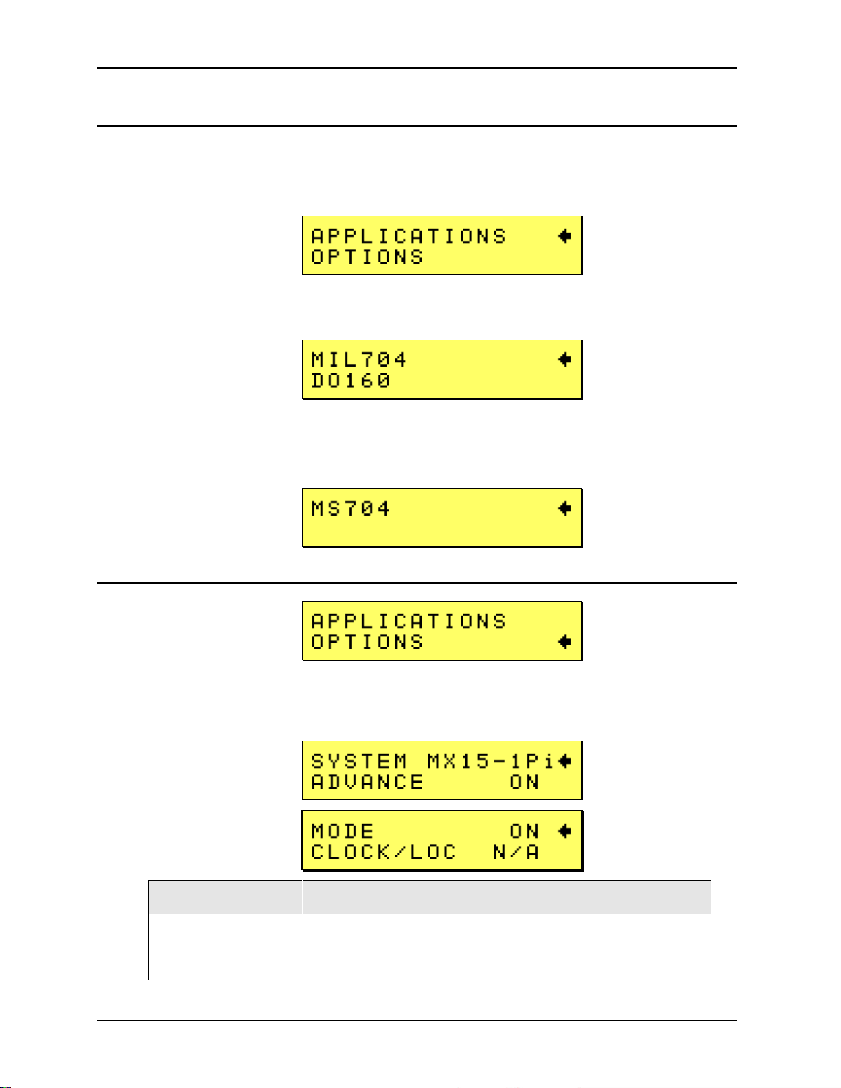
User Manual – Rev M California Instruments
ENTRY
DESCRIPTION
SYSTEM
Shows model number.
ADVANCE
ON
Designates the advanced measurement and
4.2.11 APPLICATIONS Menu
Note that some of the application options listed in this section may not be available on all MX15
models and may not be configured. In this case, these fields in these menus will display “N/A”
(not applicable) and no access to these menus will be available.
The Applications menu provides access to application specific firmware functions if available.
Note that there may be no applications installed in which case this screen will still be shown but
has no function.
Possible applications are DO160 and MIL704. To access either of the application screens,
position the cursor on the APPLICATIONS entry and press the ENTER key. Select the desired
application and press ENTER.
4.2.12 OPTIONS Menu
The Options menu provides access to available optional features. Note that there may be no
options installed in which case this screen will still be shown but has no function. The option
settings are protected and cannot be changed by the user. These screens are provided for
information purposes only.
MX15 92
Page 93
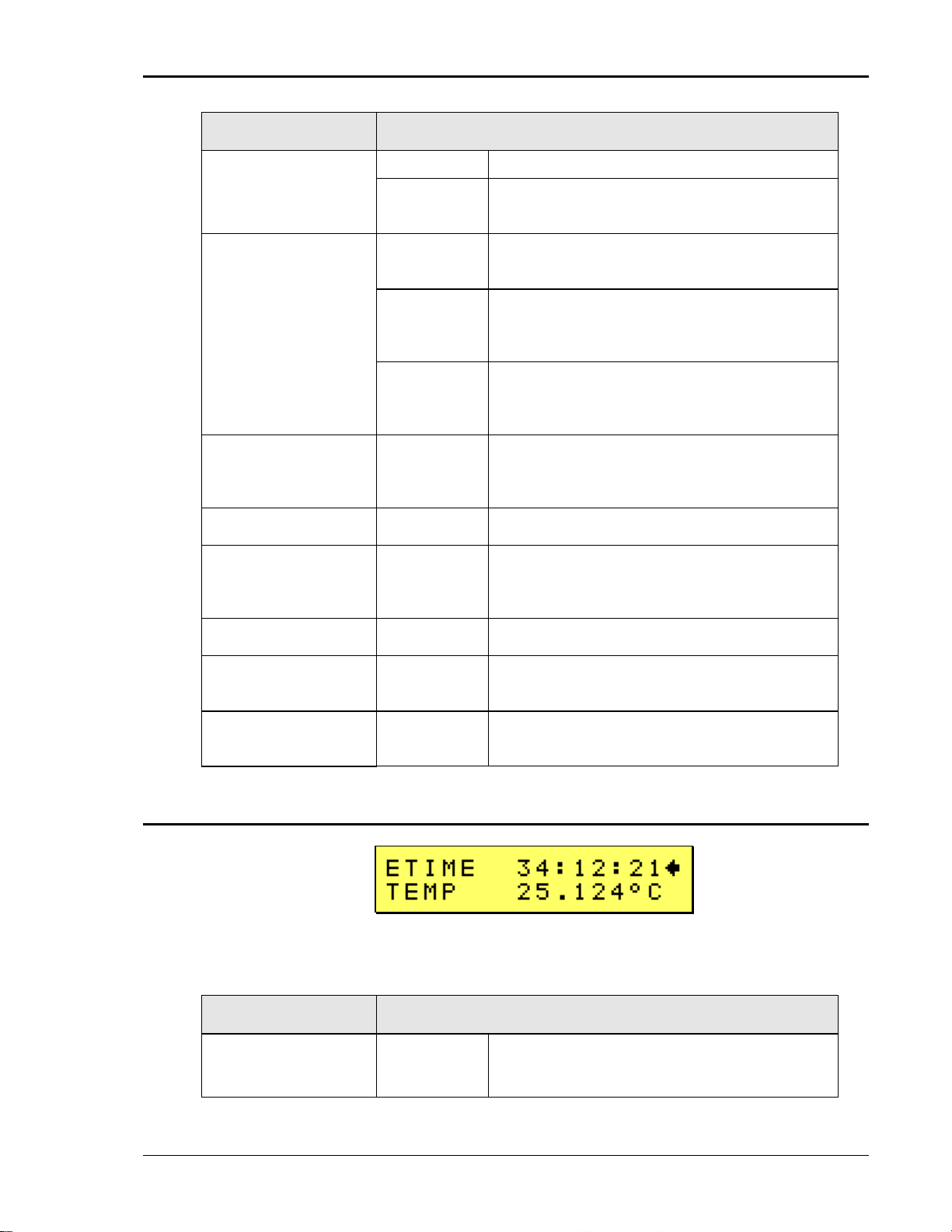
User Manual – Rev M California Instruments
ENTRY
DESCRIPTION
arbitrary waveform capability (-1Pi).
N/A
This feature is not available on –1 models. N/A
is shown.
CLOCK/LOC
N/A
Clock and lock is an option. If no –LKM option
is installed, this field will show N/A.
MAST
-LKM Option installed. The unit can be used
as a Clock and Lock system master or standalone.
AUX
-LKS option installed. The unit can be used as
a Clock and Lock system auxiliary or standalone.
MIL704
Avionics test - MIL-STD 704 revs D and E
Option (as interpreted by AMETEK at time of
release)
DO160
Avionics test – RTCA DO160 Option
MS704
Avionics test - MIL-STD 704 revs A through F
Option (according to Appendix A released with
rev F)
ABD
Avionics test – Airbus ABD0100.1.8 Option
LF Low Frequency Option – Frequency will be
limited to 500Hz
MB Multi-Box Option – Each MX15 in a multibox
configuration will have its own controller.
ENTRY
DESCRIPTION
ETIME
01:23:45
The ETIME field displays the total
accumulated elapsed time for the instrument
since it's initial manufacture. This value cannot
4.2.13 Elapsed Time and Temperature Screen
The Etime/Temp screen displays the elapsed time since the power source has first been turned
on. This is an accumulated total time in hours, minutes and seconds.
The same screen also displays the internal temperature of the power supply.
MX15 93
Page 94

User Manual – Rev M California Instruments
ENTRY
DESCRIPTION
be changed or reset.
TEMP
37.342°
The TEMP field is not a user selectable
parameter but rather a read-out of the internal
temperature in degrees Celsius. It is provided
for informational purposes only.
MX15 94
Page 95

User Manual – Rev M California Instruments
ENTRY
DESCRIPTION
LIM VOLT
LOW
Low Voltage
Range
Displays maximum available output voltage in
the low voltage range.
LIM VOLT
HIGH
High Voltage
Range
Displays maximum available output voltage in
the high voltage range.
LIM VOLT
Xform
Extra Voltage
Range
Displays maximum available output voltage in
the extra voltage range. (HV or EV option)
LIM FREQ
LOW
Low Frequency
Limit
Displays minimum available output frequency.
LIM FREQ
HIGH
High Frequency
Limit
Displays maximum available output frequency
LIM CURR
C range
Displays maximum available current in low
voltage range at full power.
PHASE (C)
Phase Setting
Displays phase angle for phase C. Valid values
are 120 for three-phase or mode configuration,
0 for single-phase only configuration. Any other
value indicates split (2) phase configuration.
The MX15 is single phase only, so this will
always show a value of 0.
4.2.14 LIMIT Menu
The Limit menu displays the maximum available value for voltage, frequency and current range
of the power supply. This screen is used for information only and contains no user changeable
fields. The limit values shown cannot be changed.
MX15 95
Page 96

User Manual – Rev M California Instruments
4.3 Output Programming
4.3.1 Set the Output
Output parameters are all set from the PROGRAM screen.
1. Use the MENU key and select the PROGRAM entry.
2. Press the ENTER key to bring up the PROGRAM menu.
or
2. Use the SET key to directly bring up the PROGRAM menu.
There are two methods for programming output parameters:
IMMEDIATE mode
SET mode
4.3.2 Slewing Output Values in IMMEDIATE Mode
The default mode of operation is an immediate mode in which changes to output parameters
made with the knob or the entry keypad are immediately reflected at the output.
To change the output voltage:
1. Place the cursor on the VOLT entry
2. Rotate the shuttle knob clockwise to increase the value, counterclockwise to decrease the
value or use the Keypad to enter a value and press the Enter key.
These changes take effect immediately.
To change the output frequency:
1. Place the cursor on the FREQ entry
2. Rotate the shuttle knob clockwise to increase the value, counterclockwise to decrease the
value or use the keypad to enter a value and press the Enter key.
These changes take effect immediately.
MX15 96
Page 97
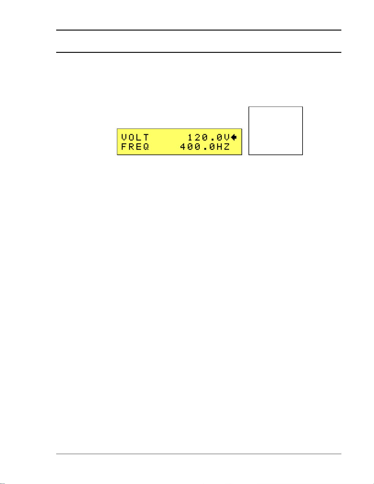
User Manual – Rev M California Instruments
4.3.3 Change Output Values in SET Mode
The SET mode of operation is a mode in which changes to output parameters made with the
knob or the entry keypad do not affect the output until the Enter key is pressed. The AC source
is put in this SET mode by pressing the Set key twice. A blinking cursor indicates SET mode is
active.
To change the output voltage:
1. Press the Set key twice
2. Place the cursor on the VOLT entry
3. Rotate the shuttle knob clockwise to increase the value, counterclockwise to decrease the
value or enter a new value using the keypad but do not press the Enter key yet.
4. A blinking underline cursor will appear in the data for the VOLT field to indicate a change in
settings but the output remains unchanged.
5. Place the cursor on the FREQ entry using the down arrow key.
6. Rotate the shuttle knob clockwise to increase the value, counterclockwise to decrease the
value or enter a new value using the keypad but do not press the Enter key yet.
7. A blinking underline cursor will appear in the data for the FREQ field to indicate a change in
settings but the output remains unchanged.
8. Press the Enter key.
Both new voltage and frequency output values are now present at the output. The unit has
returned to immediate mode of operation until the SET key is pressed again.
Note that output settings such as voltage and frequency can be changed from the measurement
screen as well. If all three phases are selected on three phase models, slewing the shuttle knob
will change the output voltage on all three phases. If only one phase is selected, only the output
of the selected phase will be affected.
MX15 97
Page 98

User Manual – Rev M California Instruments
4.4 Waveform Management [1Pi Controller only]
The MX Series with 1Pi controller employs independent arbitrary waveform generators for each
phase. This allows the user to create custom waveforms. In addition, three standard waveforms
are always available. This chapter covers issues that relate to defining, downloading and
managing custom waveforms.
4.4.1 Standard Waveforms
For most AC applications, a sine wave shape is used. The sine wave is one of the standard
waveforms provided on all MX Series models. This standard sine wave is always available and is
the default waveform at power-on. On MX models with the 1Pi controller, two more standard
waveforms are available, square and clipped.
Figure 4-7: Selecting a Waveform
The square wave provides a high frequency content waveform with relative fast rise and fall
times. Due to AC amplifier bandwidth limitations, the frequency content of the standard square
wave has been kept within the amplifier’s capabilities. As the fundamental frequency is
increased, the relative contribution of higher harmonics is reduced.
The clipped sine wave may be used to simulate voltage distortion levels to the unit under test.
The total harmonic distortion level may be programmed in percent using the CLIP THD field of
the PROGRAM menu. Changing the distortion level of the CLIP waveform forces the AC source
to regenerate the CLIPPED sine wave’s data points and reload the waveform register with the
newly requested data. This process requires the output to be dropped. To avoid interrupting the
voltage output to the unit under test, select a different waveform such as the standard sine wave
first, change the clip level and change the waveform back to the CLIPPED sine wave. This will
avoid any output interruption.
4.4.2 Creating Custom Waveforms
The 1Pi controller provides four groups of 50 custom defined waveforms each for a total of 200
waveforms in addition to the 3 standard waveforms. Of these four groups, one may be active at a
time.
Custom waveforms cannot be created from the front panel of the MX Series. Rather, they have
to be downloaded through the IEEE-488 or RS232C interface. A Windows based program is
included with the MX Series that allows waveforms to be created and downloaded easily. This
Graphical User Interface program allows waveforms to be created by specifying harmonic
amplitudes and phase angles with respect to the fundamental. It also offers an arbitrary
waveform data entry mode that allows individual data points to be specified.
MX15 98
Page 99

User Manual – Rev M California Instruments
Figure 4-8: Custom Waveform Creation with GUI Program
Once downloaded, waveforms remain in non-volatile memory and will be visible in the
PROGRAM menu for selection. The user can assign a 12-character name to each custom
waveform. Avoid using any of the standard waveform names (SINE, SQUARE or CLIPPED) as
these names will not be accepted.
Waveforms may be deleted using the IEEE-488 or RS232C interface as well. Custom waveforms
cannot be deleted from the front panel however to avoid accidental erasure.
4.4.3 Waveform Groups
Waveform groups extend the number of available custom waveform to 200. Each group can
contain up to 50 user-defined waveforms. Groups are numbered 0 through 3 and may be
selected only by using the included Gui. To switch waveform groups, proceed as follows:
1. Establish a connection to the unit using RS232 or GPIB interface with the provided Gui.
Send the command: PONS:WGR x, where x is 0-3 depending on which group is to be
selected.
2. To activate your new selection, YOU MUST CYCLE THE POWER so the AC source reinitializes. If the source is operated over the bus, a IEEE-488 Device Clear or reset command
(*RST) command will have the same effect.
The new wave group will be active after you turn the power to the unit back on.
4.4.4 RMS Amplitude Restrictions
The output of a sine wave may be programmed to the full rms value of the voltage range
selected. If the AC source is in the 300 V range, the maximum programmable rms voltage is 300
Volt. If a custom waveform is used however, the maximum programmable rms voltage may be
less than the maximum range value. The voltage range limit is based on the use of a sine wave
with a 1.414 crest factor. A 300 V rms sine wave has a 424 Volt peak voltage. The AC source
has a maximum peak voltage capability that is determined by the selected voltage range. If the
user selects a custom waveform with a crest factor that is higher than 1.414, the peak voltage
would exceed this maximum if the rms voltage were to be programmed at 300 V rms.
MX15 99
Page 100

User Manual – Rev M California Instruments
The MX Series power source automatically limits the maximum allowable programmed rms
voltage of any custom waveform by calculating the crest factor of the selected waveform and
controlling the rms limit accordingly. Thus, each custom waveform may have a different
maximum rms value. The 1Pi controller will prevent the user from programming the rms voltage
above this limit. If a value is entered in the PROGRAM menu above this value, a “Voltage peak
error” message is generated.
Figure 4-9: Waveform Crest Factor Affects Max. rms Voltage
The figure shown here illustrates the relationship between the crest factor of the wave shape (or
its “peakiness”) and the maximum peak voltage allowed for a given voltage range. Since the
peak voltage cannot exceed the AC source’s capabilities, the programmable rms voltage has to
be restricted, in this case to only 167.8785 volt for the waveform on the left. The sine wave on the
right can be programmed to the full 300 V rms as this still falls within the same peak voltage
limitation of the AC source.
If the MX Series is used over the bus, the “:VOLT? MAX” query command can be used to
determine the maximum allowable RMS voltage for the selected waveform. Using the returned
value as part of a program will prevent range errors.
4.4.5 Frequency Response Restrictions
The user may create a waveform that contains any number of harmonic frequencies of the
fundamental. The AC Source itself however has a finite signal bandwidth and will attenuate
higher frequency components of the signal. To limit the maximum frequency component of the
output signal, the 1Pi controller automatically applies a band-pass filter to all custom waveforms
as they are downloaded. The controller implements the following process for user defined
waveforms:
Each down loaded waveform will have a computed frequency limit that is less than or equal the
maximum frequency limit of the AC source. The frequency limit is a function of the harmonics
content of the waveform and will follow the equation below.
Fmaxh = Fmax/(level * hn)
If Fmaxh is below the minimum frequency limit, the waveform will be rejected at down load time
and the label will be deleted from the waveform catalogue.
If the MX Series is used over the bus, the “:FREQ? MAX” query command can be used to
determine the maximum allowable fundamental frequency for the selected waveform. Using the
returned value as part of a program will prevent range errors.
Limits assume a program of full-scale voltage. No adjustments for voltage setting are made
below the full-scale value.
MX15 100
 Loading...