

Page 1
User Manual
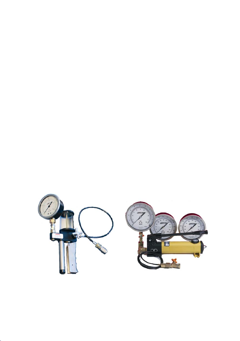
Portable Pressure Calibration Set
MGC-LOW, MGC-HIGH
Copyright 2004 AMETEK DENMARK A/S
Page 2
About this manual….
• The structure of the manual
This user manual is aimed at users who are familiar with
Ametek pressure calibration systems, as well as those who are
not. The manual is divided into 9 chapters which describe how
to set up, operate, service and maintain the pressure calibration
system. The technical specifications are described and
accessories may be ordered from the list of accessories.
• Safety symbols
This manual contains a number of safety symbols designed to
draw your attention to instructions which must be followed when
using the instrument, as well as any risks involved.
Warning
Events which may compromise the safe use of
the instrument and result in considerable
personal or material damage.
Caution…
Events which may compromise the safe use of
the instrument and result in slight personal or
material damage.
Note…
Special situations which demand the user’s
attention.
2 24-08-2004 124945 00
Page 3

List of contents
Introduction ..............................................................................4
1.0
2.0 Safety instructions ...................................................................6
3.0 Identifying your pressure calibration system.......................8
3.1 Model description.......................................................................... 8
3.2 Receipt of the pressure calibration system .................................. 9
4.0 Operating instructions...........................................................11
4.1 Operating the MGC-LOW ........................................................... 11
4.1.1 Media to be used............................................................ 13
4.1.2 After calibration .............................................................. 14
4.2 Operating the MGC-HIGH .......................................................... 15
4.2.1 Media to be used............................................................ 18
4.2.2 After calibration .............................................................. 18
4.3 Operating the optional Lloyds valve system with clamp............. 19
5.0 Errors.......................................................................................22
5.1 Re-calibration.............................................................................. 23
6.0 Returning the pressure calibration set for service ............24
7.0 Maintenance............................................................................26
7.1 Cleaning...................................................................................... 26
8.0 Technical specifications........................................................27
9.0 List of accessories .................................................................30
124945 00 24-08-2004 3
Page 4

1.0 Introduction
Congratulations on your new Ametek Portable
Pressure Calibration Set!
With the Ametek Portable Pressure Calibration Set, you have chosen
an extremely effective pressure system which we hope will live up to
all your expectations. Over the past many years, we have acquired
extensive knowledge of industrial precision pressure calibration. This
expertise is reflected in our products which are all designed for daily
use in an industrial environment. Please note that we would be very
interested in hearing from you if you have any ideas or suggestions
for changes to our products.
This user manual applies to the following systems:
• MGC-LOW, System 1
• MGC-LOW, System 2
• MGC-LOW, System 3
• MGC-HIGH, System 1
• MGC-HIGH, System 2
• MGC-HIGH, System 3
• MGC-HIGH, System 4
ISO-9001 certified
)
4 24-08-2004 124945 00
Ametek Denmark A/S was awarded the
ISO-9001 certificate in September 1994 by
BVQI - Bureau Veritas Quality International.
Page 5

) CE-label
Your new pressure calibration system bears
the CE label and conforms to the EMC
directive and the Low-voltage Directive.
) Technical assistance
Please contact the dealer from whom you acquired the pressure
calibration system if you require technical assistance.
) Guarantee
According to current terms of sale and delivery.
This guarantee only covers defects in manufacture and becomes
void if the pressure calibration system has been subject to
unauthorised intervention and/or misuse.
124945 00 24-08-2004 5
Page 6
2.0 Safety instructions
Read this manual carefully before using
the pressure system!
Please follow the instructions and procedures described in
this manual. They are designed so that you get the most
out of your pressure system and avoid any personal
injuries and/or damage to the system.
Warning……
About the handling:
• Avoid knocking, bumping or dropping the pressure
system. This can cause permanent damage to the
system and loss of accuracy.
About the use:
• The pressure system must not be used for any
purposes other than those described in this manual and
for any application other than precision pressure
calibration jobs.
• The pressure system should only be used by TRAINED
PERSONNEL.
• Never subject the pressure gauges to overpressure. In
case of overpressure the gauge should not be used for
calibration purposes.
• None of our calibration systems are cleaned or
prepared for OXYGEN OBJECTS so DO NOT USE our
systems for this purpose.
• Do not disconnect any parts from the system when
pressurised.
• Do not connect any external pressure source to this
instrument. This unit is designed to test pressure
measuring devices connected to the manifold only.
Pressure from an external source can result in
explosion of the liquid reservoir and possible personal
injuries.
6 24-08-2004 124945 00
Page 7

Note…
The product liability only applies if the pressure system is
subject to a manufacturing defect. This liability becomes
void if the user fails to follow the maintenance instructions
set out in this manual or uses unauthorised spare parts.
124945 00 24-08-2004 7
Page 8

3.0 Identifying your pressure calibration
system
3.1 Model description
MGC-LOW
The JF Model MGC-LOW consists of 2 dual scaled precision
pressure gauges with ±1% F.S.
• System 1 : 0 – 6 BAR & Kg / cm² and 0 – 16 BAR & Kg / cm²
• System 2 : 0 – 16 BAR & Kg / cm² and 0 – 40 BAR & Kg / cm²
• System 3 : 0 – 40 BAR & Kg / cm² and 0 – 100 BAR & Kg / cm²
MGC-HIGH
The JF Model MGC-HIGH consists of 3 or 4 dual scaled precision
pressure gauges with ±0.6% F.S.
• System 1 : 0 – 6 BAR & Kg / cm², 0 – 16 BAR & Kg / cm² and
0 – 40 BAR & Kg / cm²
• System 2 : 0 – 10 BAR & Kg / cm², 0 – 40 BAR & Kg / cm²,
0 – 100 BAR & Kg / cm² and 0 – 300 BAR & Kg / cm²
• System 3 : 0 – 10 BAR & Kg / cm², 0 – 40 BAR & Kg / cm² and
0 – 100 BAR & Kg / cm²
• System 4 : 0 – 10 BAR & Kg / cm², 0 – 40 BAR & Kg / cm² and
0 – 300 BAR & Kg / cm²
Both models are supplied with a hydraulic hand pump fitted with
hose, valve and couplings all delivered in a handy carrying case.
The precision pressure gauges are all dual scaled in BAR and kg/cm²
and are designed for marine use.
The calibrator is easy to operate and the hydraulic pump very rapidly
produces the required testing pressure. The calibrator quickly shows
the user if there is an indication error on a pressure gauge or valve
and how large it is. When the size of the error is known, it is possible
to compensate for it or note it – and thereby only replace faulty
pressure indicators.
8 24-08-2004 124945 00
Page 9
3.2 Receipt of the pressure calibration system
The pressure calibration system is delivered as standard in a carrying
case and should always be placed in the case after use.
When you receive the pressure calibration system…
• Carefully unpack and check the pump, the pressure gauges and
the accessories.
• Check the parts off against the list shown below.
If any of the parts are missing or damaged, please contact the
dealer who sold the pressure calibration system.
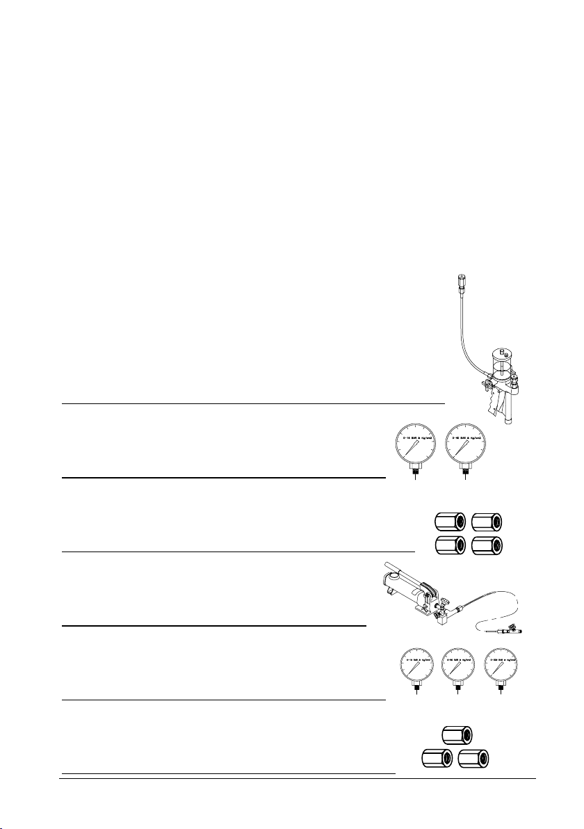
You should receive:
• 1 pump system T-620 incl. 0.5 m hose (MGC-LOW)
• 2 precision pressure gauges (3/8” BSP)
(MGC-LOW)
• 4 adapters (1/4” x 1/4” BSP, 1/4” x 3/8” BSP,
1/2” x 1/4” BSP, 1/4" x 3/4" BSP) (MGC-LOW)
• 1 pump system P-142 incl. 0.5 m hose
(MGC-HIGH)
• 3 precision pressure gauges (3/8” BSP)
(MGC-HIGH)
• 3 adapters (1/4” x 1/4” BSP, 1/2” x 1/4”
BSP, 1/4" x 3/4" BSP) (MGC-HIGH)
124945 00 24-08-2004 9
Page 10
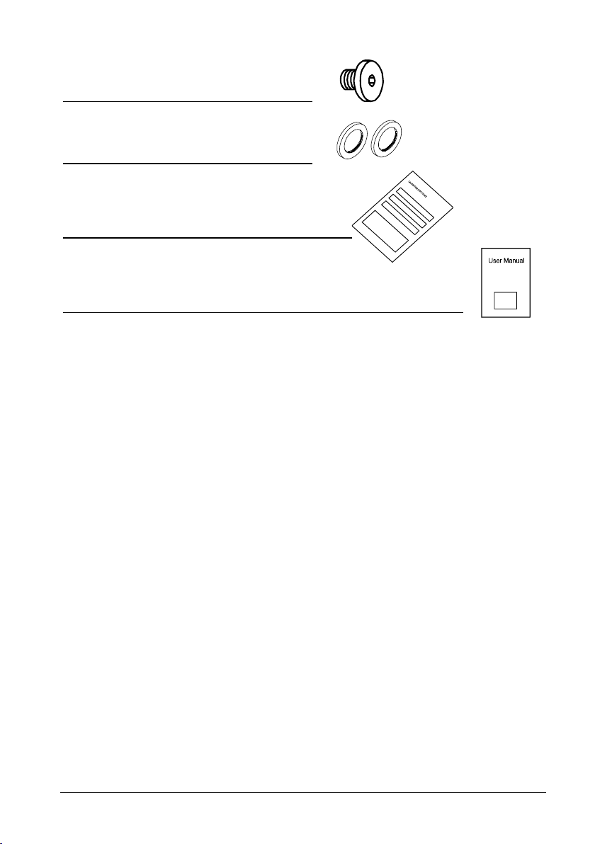
• 1 plug 1/4" BSP
• 2 bonded seal 1/4" BSP
• 1 traceable certificate per gauge
• 1 user manual
10 24-08-2004 124945 00
Page 11

4.0 Operating instructions
4.1 Operating the MGC-LOW
Warning……
About the handling:
• Avoid knocking, bumping or dropping the pressure
system. This can cause permanent damage to the
system and loss of accuracy.
About the use:
• The pressure system must not be used for any
purposes other than those described in this manual.
• Do not use this system for any applications other than
precision pressure calibration jobs.
• The pressure system should only be used by TRAINED
PERSONNEL.
• Never subject the pressure gauges to overpressure. In
case of overpressure the gauge should not be used for
calibration purposes.
• None of our calibration systems are cleaned or
prepared for OXYGEN OBJECTS so DO NOT USE our
systems for this purpose.
• Do not disconnect any parts from the system when
pressurised.
• Do not connect any external pressure source to this
instrument. This unit is designed to test pressure
measuring devices connected to the manifold only.
Pressure from an external source can result in
explosion of the liquid reservoir and possible personal
injuries.
• Follow these instructions carefully to avoid damage to
the pump and/or personal injuries.
124945 00 24-08-2004 11
Page 12

5
4
3
SYSTEM 1
0 - 6 Kg/cm2 0 - 16 Kg/cm2
Bar
Bar
1
6
Fig. 1
Warning
Before use the precision pressure gauge should be placed
in a vertical position (fig. 1) with no pressure applied and
zero pressure should be indicated. If this is not the case,
the pressure gauge may have been subjected to overpressure and should not be used for calibration purposes.
SYSTEM 2
SYSTEM 3
0 - 16 Kg/cm2 0 - 40 Kg/cm2
Bar
0 - 40 Kg/cm2
Bar
0 - 100 Kg/cm2
4
2
Bar
Bar
12 24-08-2004 124945 00
Page 13

This routine must be followed in order to operate the system correctly
(see fig. 1 accordingly).
1. Make sure that the system to be tested is depressurised.
2. Open the pump valve (pos. 1) to release pump pressure.
Make sure that the pressure system is depressurised.
3. Connect the precision pressure gauge to the pump (pos. 2).
4. Dismount the plug (pos. 3) from the hose and connect the
object for calibration (pos. 4).
4. If other connectors than those supplied are needed, please
Note…
After connection of all parts and before pressure is created
the air can be released from the system by loosening the
connectors (pos. 5). It is now possible to pump out oil and
air until no air is left in the oil.
use fittings with correct pressure rating and correct threading
and use the necessary sealing material to avoid leakage in
the pressure system.
5. Close the pump valve (pos. 1).
6. Operate the pump handle (pos. 6) gently to pressurise the
system.
7. Read the pressure on the precision pressure gauge and on
the object for calibration and repeat step 6 to proceed with
the calibration.
4.1.1 Media to be used
Oil
Use hydraulic oils: Jack oil, Exxon Nuto HP15 or H15, Tellus T14 or
the like.
Water
Use distilled water only.
124945 00 24-08-2004 13
Page 14

Other fluids
Contact AMETEK DENMARK if you want to use other fluids than
those stated above. For example SKYDROL or the like.
4.1.2 After calibration
1. Open the pump valve (pos. 1).
2. Make sure that the pressure system is depressurised before
all items are disconnected.
3. Disconnect all items.
4. Close the pump valve (pos. 1).
5. Remount the plug on the hose (pos. 3) to avoid leakage of
oil.
6. Clean all parts and put them back in the carrying case.
14 24-08-2004 124945 00
Page 15

4.2 Operating the MGC-HIGH
Warning……
About the handling:
• Avoid knocking, bumping or dropping the pressure
system. This can cause permanent damage to the
system and loss of accuracy.
About the use:
• The pressure system must not be used for any
purposes other than those described in this manual.
• Do not use this system for any applications other than
precision pressure calibration jobs.
• The pressure system should only be used by TRAINED
PERSONNEL.
• Never subject the pressure gauges to overpressure. In
case of overpressure the gauge should not be used for
calibration purposes.
• None of our calibration systems are cleaned or
prepared for OXYGEN OBJECTS so DO NOT USE our
systems for this purpose.
• Do not disconnect any parts from the system when
pressurised.
• Do not connect any external pressure source to this
instrument. This unit is designed to test pressure
measuring devices connected to the manifold only.
Pressure from an external source can result in
explosion of the liquid reservoir and possible personal
injuries.
• Follow these instructions carefully to avoid damage to
the pump and/or personal injuries.
124945 00 24-08-2004 15
Page 16

SYSTEM 1
SYSTEM 2
SYSTEM 3
SYSTEM 4
1
0 - 6 Kg/cm2 0 - 16 Kg/cm2
Bar
0 - 10 Kg/cm2 0 - 40 Kg/cm2
Bar
0 - 10 Kg/cm2
Bar
0 - 10 Kg/cm2
Bar
0 - 40 Kg/cm2
0 - 40 Kg/cm2
7
3
Bar
Bar
Bar
Bar
0 - 40 Kg/cm2
Bar
0 - 100 Kg/cm2
Bar
0 - 100 Kg/cm2
Bar
0 - 300 Kg/cm2
Bar
0 - 300 Kg/cm2
Bar
4
9
2
8
6
5
Fig. 2
16 24-08-2004 124945 00
Warning
Before use the precision pressure gauge should be placed
in a vertical position (fig. 2) with no pressure applied and
zero pressure should be indicated. If this is not the case,
the pressure gauge may have been subjected to overpressure and should not be used for calibration purposes.
Page 17

This routine must be followed in order to operate the system correctly
(see fig. 2 accordingly).
1. Set the filling valve (pos. 1) on the hand pump in position
“Vent”.
2. Open both pump valves (pos. 2 and 3) to release pump
pressure.
Make sure that the pressure system is depressurised.
3. Connect the precision pressure gauge to the pump (pos. 4)
and connect the object for calibration (pos. 5).
4. If other connectors than those supplied are needed, please
Note…
After connection of all parts and before pressure is created
the air can be released from the system by loosening the
connectors (pos. 6). It is now possible to pump out oil and
air until no air is left in the oil.
use fittings with correct pressure rating and correct threading
and use the necessary sealing material to avoid leakage in
the pressure system.
5. Close the pump valve (pos. 2) on the right side of the pump.
6. Operate the pump handle (pos. 7) gently to pressurise the
system.
7. When the required pressure is reached, close the pump
valve (pos. 3) mounted on the front part of the pump. The
gauge valve (pos. 8) (orange handle) can be used to fine
adjust the pressure.
8. Read the pressure on the precision pressure gauge and on
the object for calibration and repeat step 6 to proceed with
the calibration.
124945 00 24-08-2004 17
Page 18

4.2.1 Media to be used
Oil
Use hydraulic oils: Jack oil, Exxon Nuto HP15 or H15, Tellus T14 or
the like.
Other fluids
Contact AMETEK DENMARK if you want to use other fluids than
those stated above. For example SKYDROL or the like.
4.2.2 After calibration
1. Open the pump valve (pos. 2) on the right side of the pump.
2. Open the pump valve (pos. 3) on the front of the pump gently
to protect the gauges from the pressure shock.
3. Make sure that the pressure system is depressurised before
all items are disconnected.
4. Disconnect all items.
5. Close the filling valve (pos. 1) and the gauge valve (pos. 8).
6. Close the valve (pos. 9) on the adapter mounted on the hose
to avoid leakage of oil.
7. Clean all parts and put them back in the carrying case.
18 24-08-2004 124945 00
Page 19

4.3 Operating the optional Lloyds valve
system with clamp
Warning……
About the use:
• The Lloyds valve system with clamp must not be used
for any purposes other than those described in this
manual.
• Do not use this system for any applications other than
precision pressure calibration jobs.
• Never subject the valve system to overpressure.
• Do not disconnect any parts from the system when
pressurised.
• Follow these instructions carefully to avoid damage to
the Lloyds valve system and/or personal injuries.
124945 00 24-08-2004 19
Page 20

r
6
3
2
5
4
MGC-HIGH
Pressure system
with test connecto
1
7
MGC-LOW
Fig. 3
Some pressure systems with gauges are prepared for test fitted with
a valve with test connector.
To operate this kind of system a Lloyds valve system with clamp from
Ametek Denmark A/S can be used.
20 24-08-2004 124945 00
Page 21

This routine must be followed in order to operate the system correctly
(see fig. 3 accordingly).
1. Make sure that the system to be tested (pos. 1) is
depressurised.
2. Connect the Lloyds valve system to the 1/4" adapter
mounted on the hose (pos. 2).
3. Start pumping out oil from the MGC calibrator system until
the oil is coming out of the Lloyds valve system.
4. Close the Lloyds valve system (pos. 3).
5. Connect the Lloyds valve system to the valve with test
connector located on the system, which is to be tested (pos.
4).
6. Open the valve on the system to be tested (pos. 5).
7. Open the Lloyds valve system (pos. 6).
8. Create pressure by operating the MGC-pump (pos. 7).
9. Read the pressure on the precision pressure gauge and on
the object for calibration and repeat step 8 to proceed with
the calibration.
10. Release the pressure and close the valve on the system to
be tested (pos. 5).
11. Close the Lloyds valve system (pos. 3) and disconnect it
from the pressure system with test connector (pos. 1).
124945 00 24-08-2004 21
Page 22

5.0 Errors
Generally the AMETEK Portable Pressure Calibration Set is
manufactured for field use and will normally cause no problems for
the user.
Due to many years of experience we hereby reveal typical question
and answers.
Note…
Ametek Denmark’s liability ceases if:
• parts are replaced/repaired using spare parts which are
not identical to those recommended by the manufacturer.
• non-original parts are used in any way when operating
the instrument.
Ametek Denmark’s liability is restricted to errors which
originated from the factory.
22 24-08-2004 124945 00
Page 23

FAILURE CAUSE ACTION
The pressure is not
stabilising
The system may be
leaking.
The compressed
medium includes air.
If you have a hose in
the pressure loop the hose will expand
and give some
movement.
Adiabatic and
thermodynamic
effects are present
within all pressure
systems.
Check all
connections.
You may have to
adjust the pressure a
few times before the
pressure is stable
enough for
calibration.
Release air.
(See Notes page 13
or 17)
The effect will
disappear rapidly.
The effect will
disappear rapidly.
Note…
Always readjust the pressure after 5 – 10 minutes to allow
time for settling of above effects.
When you operate with high pressure the sensitivity of the
system is high with regard to temperature and movements.
5.1 Re-calibration
Depending on the conditions the pressure calibration set should be
checked with certain intervals by the factory or an authorized
standard laboratory and if necessary re-calibrated.
124945 00 24-08-2004 23
Page 24

6.0 Returning the pressure calibration set
for service
When returning the pressure calibration set to the manufacturer for
service, please enclose a fully completed service information form.
Simply copy the form on the following page and fill in the required
information.
The pressure calibration set should be returned in the original
packing.
Always secure a traceable certificate for confirmation of recalibration.
24 24-08-2004 124945 00
Page 25

Service info
Customer data: Date:
Customer name and address:___________________________________________
Attention and Dept.:___________________________________________________
Fax no./Phone no.:____________________________________________________
Your order no.:_______________________________________________________
Delivery address:_____________________________________________________
Distributor name:_____________________________________________________
Instrument data:
Model and Serial no.:__________________________________________________
Warranty claimed Yes:____ No:_____ Original invoice no.:_________________
___________________________________________________________________
Pressure Service request: This instrument is sent for
calibration (please tick off):
___ Calibration as left ___ Check
___ Calibration as found and as left ___ Service
___ Accredited calibration as left ___ Repair
___ Accredited calibration as found and as left.
___________________________________________________________________
Diagnosis data/cause for return:
Diagnosis/Fault description:_____________________________________________
___________________________________________________________________
Special requests:_____________________________________________________
___________________________________________________________________
Safety precautions: if the product has been exposed to any hazardous substances, it must be
thoroughly decontaminated before it is returned to Ametek. Details of the hazardous substances
and any precautions to be taken must be enclosed.
124945 00 24-08-2004 25
Page 26

7.0 Maintenance
7.1 Cleaning
Users should/must carry out the following cleaning procedures as and
when required:
• The exterior of the instrument - Clean using water and a soft
cloth.
The cloth should be wrung out hard to avoid any water
penetrating the calibrator and causing damage.
The instrument may also be cleaned using isopropyl alcohol
when heavily soiled.
26 24-08-2004 124945 00
Page 27

8.0 Technical specifications
Pressure specifications
Specifications Model
MGC-LOW
Range : 0 – 6 BAR & kg / cm²
0 – 16 BAR & kg / cm²
0 – 40 BAR & kg / cm²
0 – 100 BAR & kg / cm²
Max. pressure : 350 BAR / 5000 PSI
Min. pressure : 0 BAR
MGC-HIGH
Range : 0 – 6 BAR & kg / cm²
0 – 10 BAR & kg / cm²
0 – 16 BAR & kg / cm²
0 – 40 BAR & kg / cm²
0 – 100 BAR & kg / cm²
0 – 300 BAR & kg / cm²
Max. pressure : 700 BAR / 10000 PSI
Min. pressure : 0 BAR
124945 00 24-08-2004 27
Page 28

Mechanical specifications
Specifications Model
MGC-LOW
Weight : 1.9 kg. / 4.2 lb.
Dimensions
LxWxH : 170 x 120 x 340 mm / 6.7 x 4.7 x 13.4 inch
Operating temp. : 10 to 40°C / 50 to 104°F
Storage temp. : 0 to 50°C / 32 to 122°F
Humidity range :
Protection class :
Wetted parts : Aluminium, brass, stainless steel,
polycarbonat
Leakage : Max. 5% over 5 minutes
Reservoir volume : 130 cm
0 to 90% RH
IP33
3
(full : 180 cm3 )
MGC-HIGH
Weight : 4.4 kg. / 9.7 lb.
Dimensions
LxWxH : 460 x 220 x 290 mm / 18.1 x 8.7 x 11.4 inch
Operating temp. : 10 to 40°C / 50 to 104°F
Storage temp. : 0 to 50°C / 32 to 122°F
Humidity range :
0 to 90% RH
Protection class :
IP33
Wetted parts : Aluminium, brass, stainless steel
28 24-08-2004 124945 00
Page 29

Leakage : Max. 3% over 5 minutes
Reservoir volume : 500 cm
3
124945 00 24-08-2004 29
Page 30

9.0 List of accessories
All parts listed in the list of accessories can be obtained from the
factory through our dealers.
Please contact your dealer for assistance if you require parts which
do not appear on the list.
List of accessories
Accessories Parts no.
Pump system T-620, System 1, 2 and 3 (MGC-LOW) 103306T3
2
Gauge, System 1; 0 – 6 BAR & kg/cm
Gauge, System 1+2; 0 – 16 BAR & kg/cm
Gauge, System 2+3; 0 – 40 BAR & kg/cm
Gauge, System 3; 0 – 100 BAR & kg/cm
(MGC-LOW) 102151
2
(MGC-LOW) 102158
2
(MGC-LOW) 102165
2
(MGC-LOW) 102172
Pump system P-142, System 1, 2, 3 and 4 (MGC-HIGH) 103306T4
2
Gauge, System 1; 0 – 6 BAR & kg/cm
Gauge, System 2+3+4; 0 – 10 BAR & kg/cm
Gauge, System 1; 0 – 16 BAR & kg/cm
Gauge, System 1+2+3+4; 0 – 40 BAR & kg/cm
Gauge, System 2+3; 0 – 100 BAR & kg/cm
Gauge, System 2+4; 0 – 300 BAR & kg/cm
(MGC-HIGH) 100403
2
(MGC-HIGH) 100404
2
(MGC-HIGH) 100405
2
(MGC-HIGH) 100406
2
(MGC-HIGH) 100409
2
(MGC-HIGH) 100411
Carrying case (MGC-LOW) 124993
Carrying case (MGC-HIGH) 124992
T-620 pump, service kit T-656
Adapter, 1/4" x 1/4" BSP male 60R115
Adapter, 1/4" x 1/4" BSP female 60R324
Adapter, 1/4" x 3/8" BSP female 60R325
Adapter, 1/2" x 1/4" BSP female 60R326
Adapter, 1/4" x 3/4" BSP female 60R327
Lloyds valve 60R155
Clamp for valve 60R160
Bonded seal 1/4" 60R120
1.0 m (3.3 ft.) hose with 1/4" BSP female/male (MGC-LOW) 65P175
2.0 m (6.6 ft.) hose with 1/4" BSP female/male (MGC-LOW) 65P180
30 24-08-2004 124945 00
Page 31

1.5 m (4.92 ft.) hose with 1/4" BSP female/male 60I156
5.0 m (16.4 ft.) hose with 1/4" BSP female/male 60I157
User manual 124945
Quick connection set, male and female 50-REP 615
124945 00 24-08-2004 31
 Loading...