

Page 1

User manual
mA Loop Calibrator
Jofra mAcal
Page 2
Page 3

Page 4
User Manual
mAcal
mA loop Calibrator
Copyright 2005 AMETEK DENMARK A/S
Page 5

LIST OF CONTENTS
1.
INTRODUCTION
1.1 PACKING LIST ................................................................................ 2
2. SAFETY INSTRUCTIONS .................................................... 2
3. OPERATION ........................................................................ 4
3.1 DISPLAY AND KEYBOARD ........................................................... 4
3.2 SWITCHING THE MA
3.3 HOW THE CURRENT IS GENERATED .......................................... 6
3.4 HOW THE CURRENT IS MEASURED ............................................ 7
3.5 HOW THE VOLTAGE IS MEASURED ............................................ 7
3.6 HOW NEW PARAMETERS ARE SELECTED (SETUP) ................ 8
3.6.1 S
3.6.2 S
3.6.3 S
3.6.4 S
3.6.5 S
ELECTION OF
ELECTION OF
ELECTION OF
ELECTION OF
ELECTION OR DE-SELECTION OF AUTOMATIC
CAL
ON/OFF .................................................. 6
MODE .......................................................... 8
SLOPE TIME................................................ 8
STEP SIZE ................................................... 9
STEP TIME .................................................. 9
OFF
FUNCTION
9
4. ERROR SITUATIONS ........................................................ 10
4.1 TEST FOR “OPEN LOOP” ........................................................... 10
4.2 TEST FOR INCORRECT POLARITY ............................................ 10
4.3 TEST FOR “OVERRANGE”.......................................................... 10
4.4 INDICATION OF BATTERY STATUS ........................................... 11
5. HOW mAcal IS ADJUSTED (service mode) .................... 12
6. TECHNICAL SPECIFICATIONS (23°C±3°C) .................... 14
103887 02 1
Page 6
1. INTRODUCTION
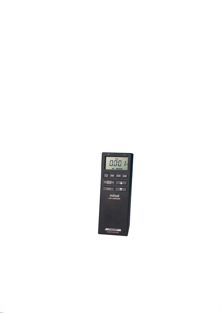
The mAcal is a loop calibrator for measuring and generating mA. The
mAcal is specially designed for use in industrial plants with 4-20mA
signals. The mAcal can be operated with one hand, and operation is simple
and intuitive.
1.1 PACKING LIST
When the instrument is received, the box should contain the following:
• mAcal
• Bag
• 2 test leads with crocodile clip
• 4 batteries, type LR6, AA
• 1 USB key containing documentation
2. SAFETY INSTRUCTIONS
Read this manual carefully before using the instrument!
In order to avoid any personal injuries and/or damage to the instrument
all safety instructions and warnings must be observed.
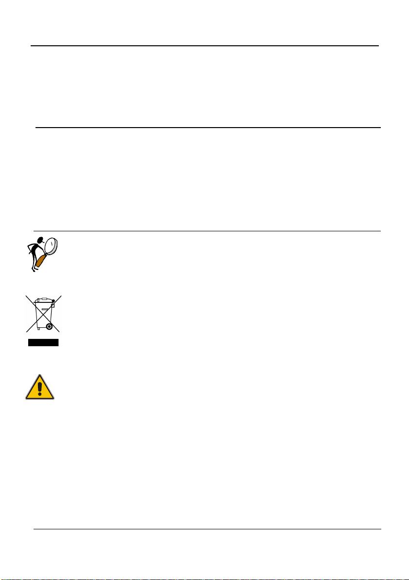
Disposal – WEEE Directive
These calibrators contain Electrical and Electronic circuits and must be
recycled or disposed of properly (in accordance with the WEEE
Directive 2012/19/EU).
WARNING:
• The calibrator must not be used for any purposes other than those
described in this manual.
• Follow all equipment safety procedures.
• The calibrator has been designed for interior use only and should
not be used in hazardous areas, where vapour or gas leaks, etc.
may constitute a danger of explosion.
• Do not apply more than the rated voltage. See specifications for
supported ranges.
• Do not use the calibrator if it is damaged. Before you use the
calibrator, inspect the case. Look for cracks or missing plastic. Pay
2 103887 02
Page 7

particular attention to the insulation surrounding the connectors.
• Select the proper function and range for your measurement.
• Make sure the battery cover is closed and latched before you
operate the calibrator.
• Remove test leads from the calibrator before you open the battery
door.
• Inspect the test leads for damaged insulation or exposed metal.
Check test leads continuity. Replace damaged test leads before you
use the calibrator.
• When using the probes, keep your fingers away from the probe
contacts. Keep your fingers behind the finger guards on the probes.
• Do not use the calibrator if it operates abnormally. Protection may
be impaired. When in doubt, have the calibrator serviced.
• Disconnect test leads before changing to another measure or
source function.
• To avoid false readings, which could lead to possible electric shock
or personal injury, replace the battery as soon as the battery
indicator appears.
• To avoid personal injury or damage to the calibrator, use only the
specified replacement parts and do not allow water into the case.
Caution…
103887 02 3
• Disconnect the power and discharge all high-voltage capacitors
before testing resistance or continuity.
• Use the proper jacks, function and range for your measurement or
sourcing application.
• To avoid damaging the plastic lens and case, do not use solvents
or abrasive cleansers.
Page 8

3. OPERATION
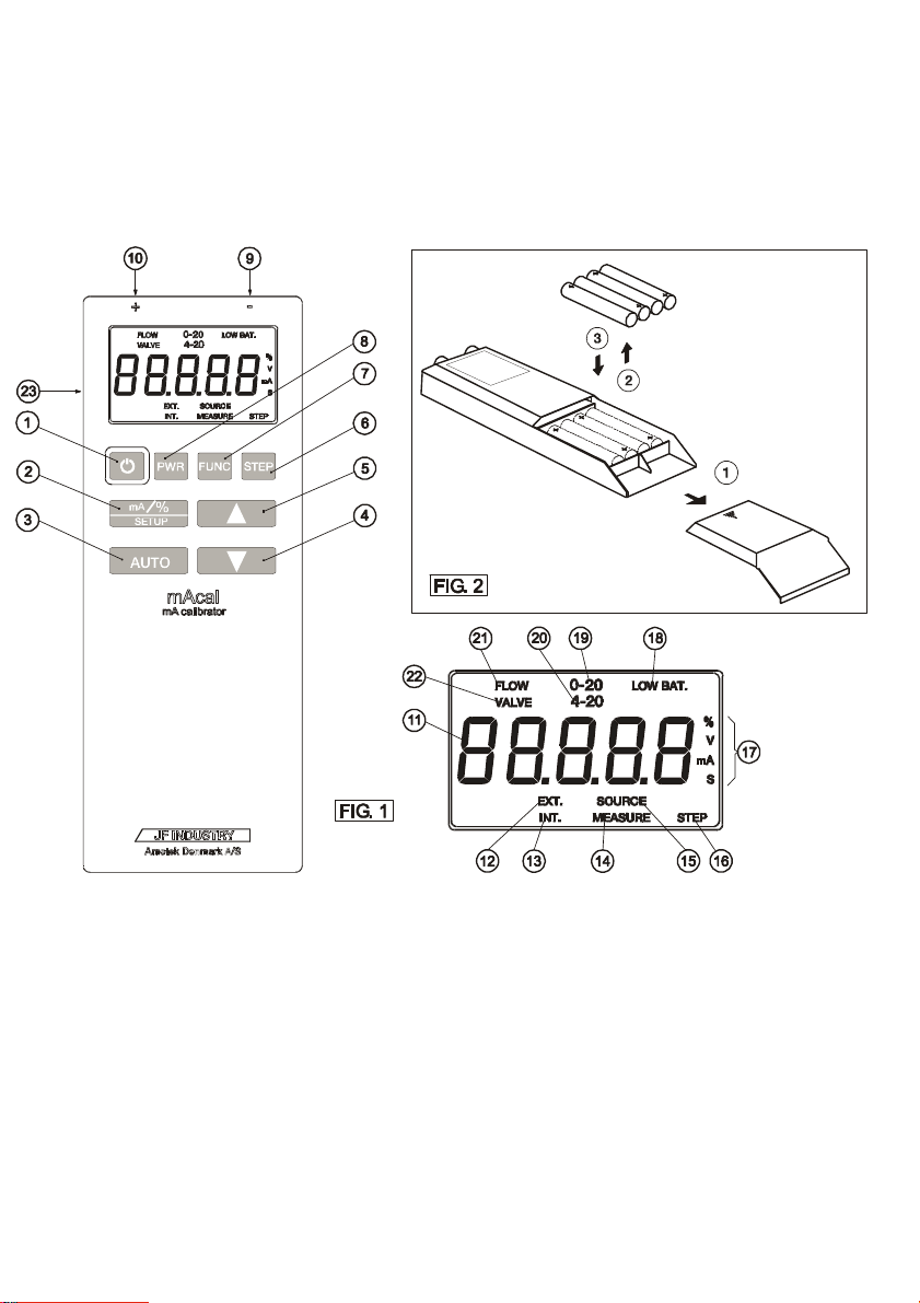
3.1 DISPLAY AND KEYBOARD
The various keys on the keyboard have the following functions (cf. Fig. 1 on the cover of
the user’s guide):
ITEM KEYBOARD Description:
ON/OFF Switching instrument on/off.
% mA / SETUP Alternating between readout in mA and %. If
AUTO AUTO ramp or AUTO-STEP function is started
DOWN ARROW “Less” key. If the key is held down, the key
UP ARROW “More” key. If the key is held down, the key
STEP The STEP function is activated or de-activated.
FUNC. (FUNCTION) Change-over takes place between SOURCE
PWR. (POWER) Change-over takes place between EXT. (the
The various segments of the display indicate the following (cf. Fig. 1 on the cover of the
user’s guide):
ITEM DISPLAY SEGMENT Description:
EXT (EXTERNAL)
INT (INTERNAL)
MEASURE
SOURCE
STEP
%, s, V or mA
the key is held down for more than 2 sec., a
change to SETUP takes place. Under SETUP
this key is used to select next parameter.
or stopped.
press is repeated.
press is repeated.
mA, MEASURE mA and MEASURE Volt
function.
+24VDC of the current loop is generated by an
external power supply) and INT. (the +24VDC
of the current loop is generated by the mAcal
itself).
Shows numerical value in mA, %, V or sec.,
and for readout of error codes etc.
External loop supply is selected.
Internal loop supply is selected, the internal
+24VDC of the mAcal being used to supply the
current loop with power.
Measurement of current or voltage is selected
(indicated by unit).
Generation of current is selected.
The STEP function is active. When the
segment flashes, this indicates that the AUTOSTEP function is activated.
Indication of unit for readout numerical values.
4 103887 02
Page 9

nectio230mA.n to mains adaptor
ITEM DISPLAY SEGMENT Description:
LOW BAT (LOW
BATTERY)
0-20
4-20
FLOW
VALVE
ITEM CONNECTIONS Description:
-
+
Con
6V DC, 230mA.
When this segment is lit, the voltage in the batteries
is less than 3.5 V, and they should be replaced.
When the segment flashes, the voltage is less
than 3.1 V and the instrument cannot be operated.
0-20mA is selected as the range, which affects the
readout in %, as well as STEP values.
4-20mA is selected as the range, which affects the
readout in %, as well as STEP values
FLOW transmitters are selected, which affects the
readout in %, as well as STEP values.
Proportional transmitters are selected, which
affects STEP values and the AUTO-STEP function.
Connection of black test lead Connection of red test lead +
Note : The mains adapter does not charge
rechargeable batteries.
103887 02 5
Page 10

3.2 SWITCHING THE mAcal ON/OFF
Press
When the unit is switched on, the present battery voltage appears in the display for approx.
1 second.
Fit the red test lead into the connector marked “+”.
Fit the black lead into the connector marked “-“.
The mAcal is now ready for use. The unit automatically starts up in the function (SOURCE
mA, MEASURE mA or MEASURE Volt) which was active when it was last switched off.
and the unit is switched on/off.
3.3 HOW THE CURRENT IS GENERATED
Connect the mAcal to the instrument to be tested as shown in Fig. 3 or Fig. 4 on the cover
of the user’s guide and switch the unit on.
Press
Press
If INT. is selected, the +24VDC of the current loop is generated by the mAcal itself. If EXT
is selected, the +24VDC of the current loop is generated by an external power supply.
Press
The display has the following appearance when 4mA is generated with internal loop
supply:
until the display shows SOURCE mA or SOURCE%.
for selection of INT or EXT (the present selection is shown in the
display).
for selection of readout in mA or %.
Press
Press
Press
on selection of MODE and STEP SIZE).
and the generated current is increased.
and the generated current is decreased.
for activation of pre-defined current values (values depend
6 103887 02
Page 11

Press
(the AUTO-STEP function), change-over takes place automatically between the
pre-defined current values. For proportional transmitters (VALVE), change-over
takes place between 3.8 - 4 - 4.2 - 4..... and 19 - 20 - 21 - 20..... mA
(the range is selected using the “up arrow” or “down arrow” keys).
The mAcal now generates the current shown in the display.
for automatic changing of current value. If STEP is selected
3.4 HOW THE CURRENT IS MEASURED
Connect the mAcal to the transmitter to be tested as shown in Fig. 5 or Fig. 6 on the cover
of the user’s guide and switch the unit on.
Press
Press
Press
If INT is selected, the +24VDC of the current loop is generated by the mAcal itself. If EXT is
selected, the +24VDC of the current loop is generated by an external power supply.
The display thus has the following appearance in the measurement of 20mA in the current
loop.
The current is printed out with a resolution of 0.001mA:
until the display shows MEASURE mA or MEASURE %
for selection of INT or EXT (the present selection is
shown in the display).
for selection of readout in mA or %.
The mAcal now measures the current shown in the display.
3.5 HOW THE VOLTAGE IS MEASURED
Connect the mAcal to the instrument to be tested as shown in Fig. 7 on the cover of the
user’s guide and switch on the unit.
Press
The display thus has the following appearance in the measurement in V. The voltage is
printed out with a resolution of 0.1Volt:
103887 02 7
until the display shows MEASURE V. Readout in %
cannot be selected.
Page 12

The mAcal now measures the voltage shown in the display.
3.6 HOW NEW PARAMETERS ARE SELECTED (SETUP)
Press
for approx. 2 seconds. The present selection of
MODE is now shown in the display, e.g.
mA.
to cancel a selection. SETUP is exited and it is necessary to
start all over again. This option can be selected at any time.
3.6.1 Selection of MODE
It is possible to choose between 5 different MODES:
• 4-20mA LIN
• 0-20mA LIN
• 4-20mA FLOW
• 0-20mA FLOW
• 4-20mA VALVE
LIN - % calculated linearly.
FLOW - % calculated logarithmically.
VALVE - % not calculated.
AUTO-STEP function 3.8 - 4 - 4.2 - 4..... or 19 - 20 - 21 - 20..... mA.
Press
Press
or
to save the present selection.
for selection of new MODE.
3.6.2 Selection of SLOPE TIME
After MODE has been selected, SLOP TIME (ramp time in the case of AUTO) can be
changed.
The text s is shown on the display for approx. 1 second.
Press
adjusted between 30 - 999 S.
Press
8 103887 02
or
to save the present selection.
for setting of SLOPE TIME. The time can be
Page 13

3.6.3 Selection of STEP SIZE
After SLOPE TIME has been selected, STEP SIZE (step size in % of range) can be
selected for the transmitter types LIN and FLOW. If MODE 4-20mA VALVE is selected,
a fixed STEP SIZE is applied. The text is shown in the display for approx. 1
second.
Press
made between the step sizes 5%, 10%, 20%, 25%, 50% and 100%.
Press
or
to save the present selection.
for setting of STEP SIZE. A choice can be
3.6.4 Selection of STEP TIME
After STEP SIZE has been selected, STEP TIME (the time between changes in the
AUTO-STEP function) can be changed. Either s or s is shown in the display.
Press
Press
or
to save the present selection.
for setting of STEP TIME.
3.6.5 Selection or de-selection of automatic OFF function
After STEP TIME has been selected, it is possible to select or de-select the AUTOMATIC
OFF function (mAcal automatically switched off approx. 30 minutes after a key has last
been activated).
The text is shown in the display for approx. 1 second. Alongside, the text or
appears.
Press
Press
Press
SETUP is exited and the mAcal is now ready for normal operation with new parameters.
and AUTOMATIC OFF is selected. appears in the
display.
and AUTOMATIC OFF is deselected. appears in the
display.
to save the present selection.
103887 02 9
Page 14

4. ERROR SITUATIONS
4.1 TEST FOR “OPEN LOOP”
The text flashes in the display:
CAUSE
REMEDY
4.2 TEST FOR INCORRECT POLARITY
The text flashes in the display:
CAUSE
REMEDY
4.3 TEST FOR “OVERRANGE”
The text flashes in the display:
CAUSE
REMEDY
The unit is unable to generate the desired current.
The current loop is probably open or selection of PWR is
incorrect.
• Check whether instrument is connected correctly.
• Check that PWR selection is correct.
The unit measures a negative current.
The test leads + and - are probably to be changed over.
The unit measures a current which is greater than 24mA or a
voltage which is greater than +45Volts or less than -45Volts.
• Measure only voltages in the range -45 to +45 Volts.
• Measure only in current loops, where the current is less
than 24mA.
• Check that the instrument is connected properly.
See Fig. 3 to Fig. 7 on the cover of the user’s guide.
10 103887 02
Page 15

inserted.
4.4 INDICATION OF BATTERY STATUS
• The text “LOW BAT” lights up in the display:
• The text “LOW BAT” flashes in the display:
CAUSE
REMEDY
“LOW BAT” lights up:
The batteries are about to be used up. However, the
instrument can still be used.
“LOW BAT” flashes:
The batteries are used up. The instrument cannot be used.
The display goes out. However, the keyed-in values are
retained.
“LOW BAT” lights up:
Change the batteries. See Fig. 2 on the cover of the user’s
guide.
“LOW BAT” flashes:
The batteries must be changed. See Fig. 2 on the cover of
the user’s guide.
The 4 used LR6, AA batteries are removed and new ones
103887 02 11
Page 16

5. HOW mAcal IS ADJUSTED (service mode)
Connect the mAcal to an external precision instrument (with an accuracy higher than
0.02% of F.S.) as shown in Fig. 3 on the cover of the user’s guide.
Hold
3 images appear in the display:
• The first display image shows the software version.
• After approx. 1 second, the serial number of the pcb is shown.
• After another approx. 1 second, the text is shown (code must be keyed in).
Press
Key in the following code:
Press
Press
Press
Press
The following display image appears:
down and press
to exit service mode. This option can be selected at any
time.
3 times.
5 times.
Twice.
Once.
Press
Press
12
or
to approve the value.
until the display shows the same value
as that measured with the external
precision instrument.
103887 02
Page 17

The following display image appears:
Press
Press
The mAcal now carries out a self-calibration and adapts its circuits to that measured.
Switch on the mAcal. It is now adjusted and ready for use.
or
to approve the value.
until the display shows the same value as
is measured with the external precision
instrument.
103887 02 13
Page 18

6. TECHNICAL SPECIFICATIONS (23°C±3°C)
Current generation :
Range : 0-24mA
Resolution : 0.01mA
Accuracy (k=2) : 0.05% F.S.
Max. load : 900 Ohm
Current measurement :
Range : 0-24mA
Resolution : 0.001mA
Accuracy (k=2) : 0.05% F.S.
Input impedance : 10 Ohm
Voltage measurement :
Range : OV to +45V
Resolution : 0.1V
Accuracy : 0.5V
Operation temperature : -10°C to +40°C
Storage temperature : -20°C to +50°C
Electromagnetic : Designed for use in basic
environment electromagnetic environment as
defined in EN61326-1 : 2013.
Battery life : 200 hours with external loop pwr.
20 hours with 12mA
output/internal loop pwr.
Battery types : 4 types LR6, AA, 1.5V – Alkaline
Mains adapter : 103950, 6V DC/230mA EURO
with 1.3 mm DC female connector
103957, 6V DC/230mA UK,
with 1.3mm DC female connector
103964, 6V DC/240mA US/JAPAN
with 1.3 mm DC female connector
Dimensions l x w x h : 174 x 66 x 26mm
Weight (incl. batteries,
bag and test leads) : 355 gr.
14
103887 02
Page 19

Standard complied with
Warrenty : (2014/30/EU), EN61326-1 : 2013
Electrical equipment for measurement,
control and laboratory use – EMC
requirements
According to current terms of sale and
Delivery. The guarantee only applies to
factory faults and ceases to apply if the
instrument has been subjected to un authorised interference and/or incorrect
operation.
103887 02 15
Page 20

AMETEK Sensors, Test & Calibration
A busine ss uni t of AMETEK Measurem ent &
Calibration Technologies Division offering the
followi ng industry l eading brand s for test and
Portable dry-block calibrators, precision
therm ometer s and li quid baths. Temper ature
Conveni ent ele ctronic syste ms ran ging from
-25 mbar to 100 0 bar - fully temp eratu re-
compensated for problem-free and accurate
Process sign al meas urement and simulat ion for
easy control lo op cali brati on and me asure ment
Pneumatic floating-ball or hydraulic piston dead
weight te sters with acc uraci es to 0.015% of
readin g. Pres sure ge nerators del iverin g up to
Digital pres sure ga uges a nd calibrator s that are
accurate, easy-to-use and reliable . Designed for
use in the h arsh est env ironments; most pr oduct s
Materials testing machines and software that
guara ntees ex per t materials tes ting so lutions.
Also covering Textu re Analyser s to per form rapid,
gener al food te sting a nd detailed tex ture a nalys is
on a diver se range of food s and cosmetic s.
Allows measur ement a nd characterizati on of
moisture-sensitive PET polymers and polymer
The han d held force gauges and m otoriz ed
tester s have ear ned their reputatio n for qua lity,
reliab ility and acc uracy and they re prese nt the de
facto standard for force measurement.
Hardness testers, durometers, optical systems
and sof tware for data a cquis ition a nd anal ysis.
calibration instrumentation.
JOFRA Calibration Instruments
Temperature Calibrators
sensors for industrial and marine use.
M&G Dead weig ht Teste rs & Pum ps
carr y an IS, IP 67 and DN V rating.
Davenport Polymer Test Equipment
Chatillon Force Measurement
Pressure Calibrators
field use.
Signal Instruments
tasks.
1,000 bar.
Crystal Pressure
Lloyd Materials Testing
dens it y.
Newage Hardness Testing
www.ametekcalibration.com
United Kingdom
Tel +44 (0)1243 833 302
caluk.sales@ametek.com
France
Tel +33 (0)1 30 68 89 40
general.lloyd-instruments@ametek.fr
Germany
Tel +49 (0)2159 9136 510
info.mct-de@ametek.de
Denmark
Tel +45 4816 8000
jofra@ametek.com
Information in this document is subject to change without notice. ©2016, by AMETEK, Inc., www.ametek.com. All rights reserved.
USA
Florida
Tel +1 (800) 527 9999
cal.info@ametek.com
California
Tel +1 (800) 444 1850
crystal@ametek.com
India
Tel +91 22 2836 4750
jofra@ametek.com
Singapore
Tel +65 6484 2388
jofra@ametek.com
China
Shanghai
Tel +86 21 5868 5111
Beijing
Tel +86 10 8526 2111
jofra.sales@ametek.com.cn
 Loading...