

Page 1

M130/M131
Ethernet Option
for DLM600 and DCS Series
Programming Manual
M362797-03 Rev F www.programmablepower.com
Page 2

Page 3

About AMETEK
AMETEK Programmable Power, Inc., a Division of AMETEK, Inc., is a global leader in the design
and manufacture of precision, programmable power supplies for R&D, test and measurement,
process control, power bus simulation and power conditioning applications across diverse
industrial segments. From bench top supplies to rack-mounted industrial power subsystems,
AMETEK Programmable Power is the proud manufacturer of Elgar, Sorensen, California
Instruments and Power Ten brand power supplies.
AMETEK, Inc. is a leading global manufacturer of electronic instruments and electromechanical
devices with annualized sales of $2.5 billion. The Company has over 11,000 colleagues working
at more than 80 manufacturing facilities and more than 80 sales and service centers in the United
States and around the world.
Trademarks
AMETEK is a registered trademark of AMETEK, Inc. Sorensen is a trademark owned by AMETEK, Inc.
Other trademarks, registered trademarks, and product names are the property of their respective
owners and are used herein for identification purposes only.
Notice of Copyright
M130/M131 Ethernet Option for DLM600 and DCS Series Programming Manual
Programmable Power, Inc. All rights reserved.
© 2002 AMETEK
Exclusion for Documentation
UNLESS SPECIFICALLY AGREED TO IN WRITING, AMETEK PROGRAMMABLE POWER, INC.
(“AMETEK”):
(a) MAKES NO WARRANTY AS TO THE ACCURACY, SUFFICIENCY OR SUITABILITY OF ANY
TECHNICAL OR OTHER INFORMATION PROVIDED IN ITS MANUALS OR OTHER
DOCUMENTATION.
(b) ASSUMES NO RESPONSIBILITY OR LIABILITY FOR LOSSES, DAMAGES, COSTS OR
EXPENSES, WHETHER SPECIAL, DIRECT, INDIRECT, CONSEQUENTIAL OR INCIDENTAL,
WHICH MIGHT ARISE OUT OF THE USE OF SUCH INFORMATION. THE USE OF ANY SUCH
INFORMATION WILL BE ENTIRELY AT THE USER’S RISK, AND
(c) REMINDS YOU THAT IF THIS MANUAL IS IN ANY LANGUAGE OTHER THAN ENGLISH,
ALTHOUGH STEPS HAVE BEEN TAKEN TO MAINTAIN THE ACCURACY OF THE
TRANSLATION, THE ACCURACY CANNOT BE GUARANTEED. APPROVED AMETEK CONTENT
IS CONTAINED WITH THE ENGLISH LANGUAGE VERSION, WHICH IS POSTED AT
WWW.PROGRAMMABLEPOWER.COM.
Date and Revision
December 2013 Revision F
Part Number
M362797-03
Contact Information
Telephone: 800 733 5427 (toll free in North America)
858 450 0085 (direct)
Fax: 858 458 0267
Email: sales.ppd@ametek.com
service.ppd@ametek.com
Web: www.programmablepower.com
i
Page 4

This page intentionally left blank.
ii
Page 5
G
G
Important Safety Instructions
Before applying power to the system, verify that your product is configured properly for your
particular application.
WARNIN
WARNIN
Only qualified personnel who deal with attendant hazards in power supplies, are allowed to perform
installation and servicing.
Ensure that the AC power line ground is connected properly to the Power Rack input connector or
chassis. Similarly, other power ground lines including those to application and maintenance
equipment must be grounded properly for both personnel and equipment safety.
Always ensure that facility AC input power is de-energized prior to connecting or disconnecting any
cable.
In normal operation, the operator does not have access to hazardous voltages within the chassis.
However, depending on the user’s application configuration, HIGH VOLTAGES HAZARDOUS TO
HUMAN SAFETY may be normally generated on the output terminals. The customer/use r must
ensure that the output power lines are labeled properly as to the safety hazards and that any
inadvertent contact with hazardous voltages is eliminated.
Guard against risks of electrical shock during open cover checks by not touching any portion of the
electrical circuits. Even when power is off, capacitors may retain an electrical charge. Use safety
glasses during open cover checks to avoid personal injury by any sudden component failure.
Neither AMETEK Programmable Power Inc., San Diego, California, USA, nor any of the subsidiary
sales organizations can accept any responsibility for personnel, material or inconsequential injury,
loss or damage that results from improper use of the equipment and accessories.
Hazardous voltages may be present when covers are removed. Qualified
personnel must use extreme caution when servicing this equipment.
Circuit boards, test points, and output voltages also may be floating above
(below) chassis ground.
The equipment used contains ESD sensitive parts. When installing
equipment, follow ESD Safety Procedures. Electrostatic discharges might
cause damage to the equipment.
SAFETY SYMBOLS
iii
Page 6

This page intentionally left blank.
iv
Page 7

Product Family: M130/M131 Ethernet Option
Warranty Period: Five Years
WARRANTY TERMS
AMETEK Programmable Power, Inc. (“AMETEK”), provides this written warranty covering the
Product stated above, and if the Buyer discovers and notifies AMETEK in writing of any defect in
material or workmanship within the applicable warranty period stated above, then AMETEK may,
at its option: repair or replace the Product; or issue a credit note for the defective Product; or
provide the Buyer with replacement parts for the Product.
The Buyer will, at its expense, return the defective Product or parts thereof to AMETEK in
accordance with the return procedure specified below. AMETEK will, at its expense, deliver the
repaired or replaced Product or parts to the Buyer. Any warranty of AMETEK will not apply if the
Buyer is in default under the Purchase Order Agreement or where the Product or any part
thereof:
is damaged by misuse, accident, negligence or failure to maintain the same as
specified or required by AMETEK;
is damaged by modifications, alterations or attachments thereto which are not
authorized by AMETEK;
is installed or operated contrary to the instructions of AMETEK;
is opened, modified or disassembled in any way without AMETEK’s consent; or
is used in combination with items, articles or materials not authorized by AMETEK.
The Buyer may not assert any claim that the Products are not in conformity with any warranty
until the Buyer has made all payments to AMETEK provided for in the Purchase Order Agreement.
PRODUCT RETURN PROCEDURE
1. Request a Return Material Authorization (RMA) number from the repair facility (must be
done in the country in which it was purchased):
In the USA, contact the AMETEK Repair Department prior to the return of the
product to AMETEK for repair:
Telephone: 800-733-5427, ext. 2295 or ext. 2463 (toll free North America)
858-450-0085, ext. 2295 or ext. 2463 (direct)
Outside the United States, contact the nearest Authorized Service Center
(ASC). A full listing can be found either through your local distributor or our
website, www.programmablepower.com, by clicking Support and going to the
Service Centers tab.
2. When requesting an RMA, have the following information ready:
Model number
Serial number
Description of the problem
NOTE: Unauthorized returns will not be accepted and will be returned at the shipper’s expense.
NOTE: A returned product found upon inspection by AMETEK, to be in specification is subject to
an evaluation fee and applicable freight charges.
v
Page 8

This page intentionally left blank.
vi
Page 9

CONTENTS
SECTION 1 FEATURES, FUNCTIONS, AND SPECIFICATIONS ..... 1-1
1.1 Introduction .................................................................................................... 1-1
1.2 Features and Functions .................................................................................. 1-2
1.2.1 Features ............................................................................................. 1-2
1.2.2 Programmable Functions ................................................................... 1-3
1.2.3 Readback Functions ........................................................................... 1-3
1.3 Specifications ................................................................................................. 1-3
1.3.1 Ethernet/LAN Configuration ................................................................ 1-3
1.3.2 Ethernet Configuration Factor y Def ault s ............................................. 1-4
1.3.3 Programming Resolution .................................................................... 1-4
1.3.4 Programming Accuracy ...................................................................... 1-4
1.3.5 Readback Resolution ......................................................................... 1-5
1.3.6 Readback Accuracy ............................................................................ 1-5
SECTION 2 CONFIGURATION ....................................................... 2-1
2.1 Setup Procedure ............................................................................................ 2-1
2.1.1 M130 Network Setup Using DHCP ..................................................... 2-1
2.1.2 M130 Network Setup Using Auto-IP ................................................... 2-2
2.1.3 M130 Network Setup Using the Serial COM Port ............................... 2-3
2.1.4 M130 Network Setup Using Web Browser .......................................... 2-4
2.2 Rear Panel ..................................................................................................... 2-5
2.2.1 M130 (Master) Option ........................................................................ 2-5
2.2.2 M131 (Slave) Option ........................................................................... 2-6
2.2.3 Configuration Switch ........................................................................... 2-8
2.2.4 Remote/Local Selection ...................................................................... 2-9
2.3 External User Control Signal Connector ....................................................... 2-10
2.4 Programm ing Via Ethernet ........................................................................... 2-12
M130/131 Programming Manual iii
Page 10

Contents Sorensen Ethernet Option
2.4.1 Communication Methods .................................................................. 2-12
2.4.2 Raw Socket Interface ........................................................................ 2-12
2.4.3 VXI-11 Protocol ................................................................................ 2-12
2.4.4 Web Server ...................................................................................... 2-12
2.4.5 Troubleshooting ................................................................................ 2-29
2.5 Remote Programming Via RS-232 ............................................................... 2-30
2.6 Extended Interf ace Bus ( EI B) with the M131 Option ..................................... 2-31
SECTION 3 IEEE 488.2 AND SCPI COMMAND OPERATION ........ 3-1
3.1 Introduction .................................................................................................... 3-1
3.2 IEEE-488.2 Regist er Definitions ..................................................................... 3-1
3.2.1 SCPI Status Byte ................................................................................ 3-1
3.2.2 Standard Event Status Register (ESR) ............................................... 3-2
3.2.3 Protection Condition and Protection Event Status Regist er s ............... 3-3
3.2.4 Operation Status and Questionable Status Reg ist er s ......................... 3-4
3.2.5 Error/Event Queue .............................................................................. 3-4
3.2.6 Serial Poll Operation ........................................................................... 3-6
3.3 IEEE-488.2 and SCPI Conformance Inform ation .......................................... 3-7
3.3.1 Parameter Definitions ......................................................................... 3-7
3.3.2 Units ................................................................................................... 3-7
3.3.3 Conventions ........................................................................................ 3-8
3.3.4 Queries ............................................................................................... 3-8
3.4 IEEE-488.2 Common Com m and Subsystem .................................................. 3-9
3.5 CALIBRATION SCPI Command Subsystem ................................................ 3-11
3.5.1 CALIBRATION SCPI Command Summary ....................................... 3-11
3.5.2 CALIBRATION SCPI Command Reference ...................................... 3-12
3.6 MEASURE SCPI Command Subsystem ....................................................... 3-15
3.6.1 MEASURE SCPI Command Summary ............................................. 3-15
3.6.2 MEASURE SCPI Command Reference ............................................ 3-15
3.7 OUTPUT SCPI Command Subsystem ......................................................... 3-16
3.7.1 OUTPUT SCPI Command Summary ................................................ 3-16
3.7.2 OUTPUT SCPI Command Reference ............................................... 3-16
3.8 SOURCE SCPI Command Subsystem ......................................................... 3-17
3.8.1 SOURCE SCPI Command Summary................................................ 3-17
3.8.2 SOURCE SCPI Command Reference .............................................. 3-18
3.8.3 THE RAMP FUNCTION .................................................................... 3-21
3.9 STATUS SCPI Command Subsystem .......................................................... 3-22
Page 11

Sorensen Ethernet Option Contents
3.9.1 STATUS SCPI Command Summary ................................................ 3-22
3.9.2 STATUS SCPI Command Reference ............................................... 3-22
3.10 SYSTEM SCPI Command Subsystem ......................................................... 3-24
3.10.1 SYSTEM SCPI Command Summary .............................................. 3-24
3.10.2 SYSTEM SCPI Command Reference ............................................. 3-25
3.11 TRIGGER SCPI Command Subsystem ........................................................ 3-29
3.11.1 TRIGGER SCPI Command Summary ............................................ 3-29
3.11.2 TRIGGER SCPI Command Reference ........................................... 3-29
3.12 Examples of Using the SCPI Commands ..................................................... 3-30
SECTION 4 CALIBRATION ............................................................ 4-1
4.1 Introduction .................................................................................................... 4-1
4.2 Setup for Calibration ...................................................................................... 4-2
4.3 Voltage Progr am m ing Calibration ................................................................... 4-3
4.4 Voltage Measurement/Readback Calibration ................................................. 4-5
4.5 Overvoltage Protection Programming ............................................................ 4-6
4.6 Current Programming Calibration ................................................................... 4-7
4.7 Current Measurement/Readback Calibration .................................................. 4-9
4.8 Update of Non-Volatile Calibration Dates ..................................................... 4-10
SECTION 5 OPERATION WITH M131 OPTION .............................. 5-1
5.1 Introduction .................................................................................................... 5-1
5.2 Configuration .................................................................................................. 5-1
5.3 System Installation ......................................................................................... 5-3
5.4 RS-485 Interface ............................................................................................ 5-4
5.5 Programm ing the M131 Unit (Example) ......................................................... 5-4
LIST OF FIGURES
Figure 2-1. Power Supply’s Home Page (DLM600 Series shown here) ....................... 2-2
Figure 2-2. Typical Rear Panel of M130 Ethernet Option for DLM600 ......................... 2-5
Figure 2-3. Typical Rear Panel of M130 Option for DCS1k and DCS1.2k .................... 2-5
Figure 2-4. Typical Rear Panel of M130 Option for DCS3k .......................................... 2-6
Figure 2-5. Typical Rear Panel of M131 Ethernet Option for DLM600 ......................... 2-6
Figure 2-6. Typical Rear Panel of M131 Ethernet Option for DCS1k and DCS1.2k ..... 2-6
Figure 2-7. Typical Rear Panel of M131 Ethernet Option for DCS3k ........................... 2-7
Figure 2-8. DLM 600W Configuration Switch for the M130 Option ............................... 2-8
Figure 2-9. DCS Configuration Switch for t he M130 Option ......................................... 2-8
Figure 2-10. External User Connector Designation (8-pin Molex) .............................. 2-10
M130/M131 Programming Manual v
Page 12

Contents Sorensen Ethernet Option
Figure 2-11. Example of Open Collector, TTL Input, and Relay Output Circuits ......... 2-11
Figure 2-12. DLM Web Pag e Banner ......................................................................... 2-13
Figure 2-13. DCS W eb Page Banner ......................................................................... 2-13
Figure 2-14. Login Window ........................................................................................ 2-14
Figure 2-15. DLM Home Page ................................................................................... 2-14
Figure 2-16. DCS Home Page ................................................................................... 2-15
Figure 2-17. DLM IP Configuration Page ................................................................... 2-16
Figure 2-18. DCS IP Configuration Pag e ................................................................... 2-16
Figure 2-19. Settings Page ........................................................................................ 2-19
Figure 2-20. Alert Message for Save Setting s ............................................................ 2-21
Figure 2-21. Status Page ........................................................................................... 2-22
Figure 2-22. Security Page ........................................................................................ 2-24
Figure 2-23. Add New User Window fr om Security Page ........................................... 2-25
Figure 2-24. Edit Existing User Window from Security Page ...................................... 2-26
Figure 2-25. Channel Allocation W indow from Security Page .................................... 2-27
Figure 2-26. Slave Information Pag e .......................................................................... 2-28
Figure 2-27. RS-232 Rear Panel RJ-11 Connector Pinout ......................................... 2-30
Figure 2-28. M130 to PC RS-232 Connection (RJ-11 to DB-9) .................................. 2-30
Figure 2-29. EIB (RS485) Rear Panel RJ-11 Connector Pinout ................................. 2-31
Figure 2-30. M130 to M131 EIB Connection (RJ-11 to RJ-11) ................................... 2-31
Figure 5-1. DLM600W Configuration for M131 set to Channel 2 .................................. 5-1
Figure 5-2. Switch Configuration f or M6 or M131 set to Channel 8 .............................. 5-2
Figure 5-3. RS-485 System Inter connection with Two Auxiliaries ................................. 5-3
Figure 5-4. M131 Rear Panel RS-485 Connectors Pinout ............................................ 5-4
LIST OF TABLES
Table 2-1 Remote/Local Switch ................................................................................... 2-9
Table 2-2 Remote Mode Power-on Conditions ............................................................. 2-9
Table 2-3 External User Control Signal Connector Pinout .......................................... 2-10
Table 3-1 SCPI Status Byte ......................................................................................... 3-2
Table 3-2 Standard Event Status Register ................................................................... 3-3
Table 3-3 Protection Condition and Event Status Registers ......................................... 3-3
Table 3-4 SCPI Error Codes ....................................................................................... 3-4
Table 3-5 Parameter Definitions................................................................................... 3-7
Table 3-6 M130 Units ................................................................................................... 3-7
Table 3-7 SOURce[n]:STATus: BLO CK? "St at us Flag s " Register............................... 3-21
Table 3-8 System Fault Registers .............................................................................. 3-28
Table 5-1 Definitions of S1 Switch Settings .................................................................. 5-2
Page 13

FEATURES, FUNCTIONS, AND
1.1 INTRODUCTION
This manual covers the M130 and M131 Remote Programming Ethernet I nterface
Options for the DLM600 Series and the DCS Series power supplies. The M130
(master interface configuration) and M131 (slave configuration) opt ions enable you
to operate your Sorensen power supply from a computer via Ethernet IEEE-802.3 or
RS-232 communication protocols, or with SCPI-compat ible language, allowing full
remote programming control and monitoring of your power supply. The M130 can
control up to 30 auxiliary (slave) power supplies
SECTION 1
SPECIFICATIONS
In addition to controlling power supplies configured with the M131 (Ethernet ) slave
option, the M130 master can control power supplies configured with the M85
(GPIB/RS232) slave option, which uses the same RS485-based Extended Interface
Bus (EIB) for master/slave control; whereas, a GPIB master (M9x) can control only
GPIB slaves (M85). This means that a single Sorensen DLM600 or DCS power
supply configured with the M130 option, can control any Sorensen power supply
(DLM600, DCS 1k, DCS 1.2k, DCS 3k), in any combination of M131 and/or M85
slave configuration options, up to as many as 30 power supplies total.
A final important point is that the M130 / M131 Ethernet options ar e
eXtensions for Instr um ent ation) class C compliant. LXI™ is an instrum ent at ion
platform based on industry-standard Ethernet technology designed to provide ease
of integration by modularity, f lexibility and perform anc e.
1.1.1 MINIMUM SYSTEM REQUIREMENTS
The minimum software and equipment r equirements to operate your Sorensen
Ethernet product depend on whether it is connected directly to your PC or connect ed
to the Internet or to a Local Area Net work ( LAN).
™ (LAN
M130/M131 Programming Manual 1-1
Page 14

Features, Functions and Specifications Sorensen Ethernet Option
PC Connection
To operate your Sorensen Ethernet product connected directly to a PC (no Internet
or LAN connection) you will need:
• Pentium-based laptop or desktop computer running Microsoft Windows XP
• Ethernet based Network Interface Card (NIC) or built -in port capable of
10/100 MBit operation
• CAT 5 cable Ethernet crossover cable
• Microsoft Internet Explorer version 6.0 or later
• Sun Microsystems Java Runtime Environment
Internet or LAN Connection
To operate your Sorensen Ethernet product connect ed t o the Internet or a LAN you
will need:
• Pentium-based laptop or desktop computer running Microsof t Windows XP
• Ethernet based Network Interface Card (NIC) or built -in port capable of
10/100 MBit operation
• Appropriate Ethernet modem for Internet connec t ion, or
• Switch or hub (Linksys brand strongly recommended) for LAN connection
• Standard CAT 5 Ethernet interconnect cable
• Microsoft Internet Explorer version 6.0 or later
• Sun Microsystems Java Runtime Environment
1.2 FEATURES AND FUNCTIONS
1.2.1 FEATURES
• Ethernet/LAN connectivity, 10/100base-T compatible
• Fully
• Built-in Web Server for direc t control using Internet Explorer 6.0 or higher
• 16-bit programming and 16-bit readback of voltage and current
• Programmable overvoltage protection with reset
• SCPI compliant command set
• User-programmable signals including Local/Remote Sense, Exter nal Polarity,
and Disconnect Relay Drive
• User selectable Constant-Voltage/Constant-Current or Foldback mode, with
reset
• Voltage Ramp and Current Ramp functions
• Field-upgradeable firmware via RS-232
• Attachment of up to 30 supplies equipped with the M131 or M85 option via
EIB interface, for a t otal of 31 supplies controlled through one IP addr ess
• Full calibration through software control
™ (LAN eXtensions for Instr umentation) class C compliant
1-2 M130/131 Programming Manual
Page 15

Sorensen Ethernet Option Features, Functions and Specifications
• Rear panel Ethernet/IEEE-802.3 and RS-232 control interface
• Rear panel User Control Signal interface
• Rear panel configuration switch
1.2.2 PROGRAMMABLE FUNCTIONS
• Output voltage and current
• Soft limits for voltage and current
• Overvoltage protection
• Output enable/disable
• Maskable fault interrupt
• Hold and trigger
• External relay control
• Full calibration
1.2.3 READBACK FUNCTIONS
• Measured voltage and current
• Voltage and current settings
• Soft voltage and current limits
• Overvoltage protection setting
• Status and Accumulated Status registers
• Programming error codes
• Fault codes
• Manufacturer, power supply model, and firmware version identification
1.3 SPECIFICATIONS
(SUBJECT TO CHANGE WITHOUT NOTICE)
1.3.1 ETHERNET/LAN CONFIGURATION
• Ethernet IEEE 802.3 compliant
• Medium 10/100 base-T
• Connection Monitoring Media Sense supported
• Protocol TCP/IP, IPV4
• ICMP (ping server) Enable (default)/Disable
• IP Address Assignment Automatic via DHCP (Primary default), Static, or
Automatic Private IP Addressing (Auto-I P, Secondar y
default)
• VXI-11 Discovery Supported
• Security Password prot ected access, and selective
permissions for each user
M130/M131 Programming Manual 1-3
Page 16

Features, Functions and Specifications Sorensen Ethernet Option
PARAMETER
DEFAULT
Host Name
S-Dxx<base model>-<last four digits of serial number>
Description
Sorensen Power Supply Dxx<base model>
DHCP-acquired (Primary default*) I f DHCP absent,
assigned via Auto-IP (Secondary default*)
IP Addressing mode
DHCP-acquired (Primary default*)
DHCP-acquired (Primary default*) If DHCP absent,
assigned via Auto-IP (Secondary default*)
Gateway
0.0.0.0
DNS Server
0.0.0.0
Listening Port
9221
User ID
admin
Password
password
Ping Echo
On
Current
0.002% of full scale
0.002% of full scale
0.002% of full scale (f ull
output voltage.)
0.002% of full scale (f ull
output voltage.)
± (0.1% + 0.1% of full
scale)
± (0.1% + 0.4% of full
scale)
max. output voltage)
1.3.2 ETHERNET CONFIGURATION FACTORY DEFAULTS
IP Address
Subnet Mask
* The Ethernet inter face provides the opportunity to set both a Primar y and a
Secondary IP configuration in the IP Conf ig uration page (Section 2.4.4). If the
Primary fails, the system defaults t o the Secondary configuration. However, both
setting DHCP-acquired and selecting “Auto IP Enabled” together in the Primary
configuration, prevents the power supply fr om t rying the Secondary configuration.
Please see “IP Configuration” in Section 2.4.4 for more detail.
1.3.3 PROGRAMMING RESOLUTION
DLM DCS
Voltage 0.002% of full scale 0.002% of full scale
Overvoltage Protection
scale is 110% of max
1.3.4 PROGRAMMING ACCURACY
DLM600 DCS
Voltage ± (0.1% of maximum output voltage)
Current ± ( 0. 25% of full scale output current
Overvoltage
Protection
± (0.5% of max output voltage)
scale is 110% of max
± (0.5% + 0.5% of full
scale) (full scale 110% of
1-4 M130/131 Programming Manual
Page 17

Sorensen Ethernet Option Features, Functions and Specifications
DLM600
DCS
Voltage
0.002% of full sc a le
0.02% of full scale
Current
0.002% of full scale
0.02% of full scale
DLM600
DCS
± (0.1% + 0.15% of
maximum output voltage)
± (0.1% + 0.4% of
maximum output current)
1.3.5 READBACK RESOLUTION
1.3.6 READBACK ACCURACY
Voltage ± (0.1% of full scale output voltage)
Current*
± (0.25% of full scale output current)
*
* After 30 minutes operation with f ixed line, load, and tem per ature.
Note: Refer to the applicable power supply manual (DLM600 or DCS) for effects of
line regulation, load regulation, and temperature on accur acy s pecif icat ions.
M130/M131 Programming Manual 1-5
Page 18

Features, Functions and Specifications Sorensen Ethernet Option
This page intentionally left blank.
1-6 M130/131 Programming Manual
Page 19

SECTION 2
CONFIGURATION
The M130 is installed into the supply at the factory. Use the Setup Procedur e described below
to configure the M130 for your system and applicat ion.
2.1 SETUP PROCEDURE
There are four methods of setting the IP address of the unit, each of which is
described in the subsections that follow:
• Set an IP address through DHCP (Primary default).
• If DHCP is not available, the unit can ass ig n it s elf an IP address in the Auto-IP
(dynamic link local addressing) range (Secondary default).
• Use the serial communications port to manually assign an IP address.
• Set the IP address through the Web page interface.
NOTE: The M130 Ethernet Option has been designed and tested to be fully
compatible with Microsoft Internet Explorer 6.0. This is the only browser supported by
Elgar Electronics Corporation (EEC) in its Ethernet-based products. Earlier versions of
Explorer (or browsers by other companies) may or may not work correct ly, and as
such, are not supported by EEC.
2.1.1 M130 NETWORK SETUP USING DHCP
Before beginning this procedure, get access to the DHCP server or see the network
administrator to get the IP address assigned to the power supply.
NOTE: The power supply is VXI-11 compliant, so even without access to the DHCP
server, it is still possible to discover the IP address assigned to the power supply
with programs such as Agilent’s I/O Library Suite or National Instrument’s NI-VISA.
1. Start with the power supply in the power-off state.
2. Connect a RJ-45 network cable from the power supply to the network with the
DHCP server.
3. Power on the power supply and allow the power supply to perform its
initialization.
M130/M131 Programming Manual 2-1
Page 20
Configuration Sorensen Ethernet Option
4. Identify the IP address assigned to the power supply by accessing the DHCP
server, asking your network administrator, or discovering it with a VXI-11
compliant discover program.
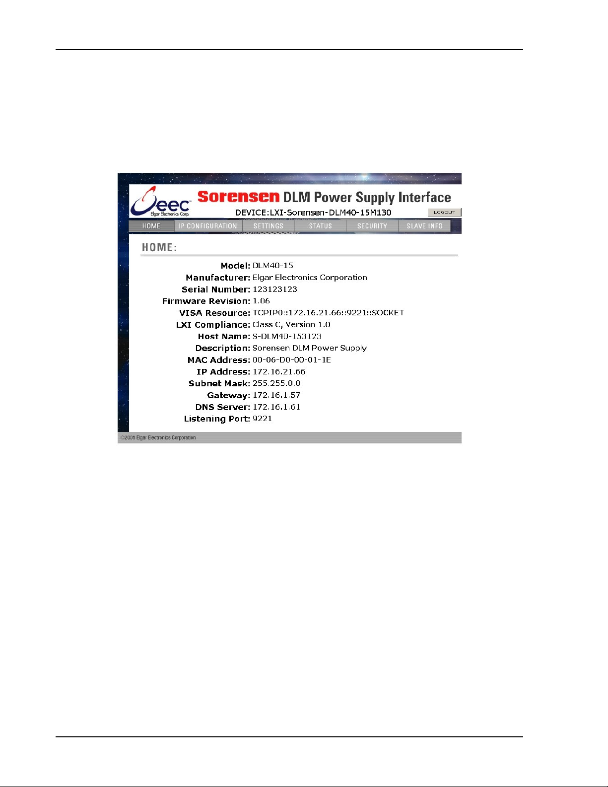
5. The M130 Ethernet hardware is now configured. Open your Web browser and
enter the IP address of the power supply to view the Home page of t he power
supply.
Figure 2-1. Power Supply’s Home Page (DLM600 Series shown here)
2.1.2 M130 (MASTER) NETWORK SETUP USING AUTO-IP
For this method, use a VXI-11 compliant discovery program such as Agilent’s I/O
Library Suite or National Instrument’s NI-VISA to discover t he IP address assigned
to the power supply. The power supply will assign itself an IP address in the IP
address range from 169. 254. 0.1 to 169.254.255.254 with a subnet mask of
255.255.0.0.
NOTE: When connecting your Sorens en Master unit to a network, Elgar strong ly
recommends using Linksys® hubs or switches, which have undergone extensive
compatibility testing with the M130 interface.
1. Start with the power supply in the power-off state.
2. Connect a crossover cable from the power supply directly to your PC.
3. If the PC is already configured to obtain an IP address automatically, skip to
Step 4. Otherwise:
2-2 M130/M131 Programming Manual
Page 21

Sorensen Ethernet Option Configuration
a. In Windows click Start, Settings, Control Panel.
b. Click open Network Connections. ( For XP, if in the Category View, click
Network and Internet Connections, and then Network Connections).
c. In the Network Connections window, right click the icon for t he network
adapter used to connect to the power supply, and click Properties.
d. Find the TCP/IP protocol item under t he Configuration tab (for XP: find
the item under the General t ab) , and c lick Properties. Select Obtain an
IP Address Automatically.
e. Click OK to save the change.
f. Click OK again t o apply the set t ings to the network adapter.
4. In Windows, click Start, and then Run…
5. I n t he Run window, type “ipconfig / r elease” and c lick OK.
6. Again click Start, and then Run…
7. I n t he Run window, type “ipconfig / r enew” and click OK. Yo ur PC will assign itself
an IP address in the Auto-IP range.
8. Power on the power supply and allow the power supply to perform its
initialization.
9. I dent ify the IP address assigned to the power supply by discovering it with a
VXI-11 compliant discover program.
10. Continue by f ollowing the proc edur e in Sect ion 2.1.4.
NOTE: When Auto-I P assigns an IP address, Web page connections will time out
after 5 minutes of inact ivity.
2.1.3 M130 NETWORK SETUP USING THE SERIAL COM PORT
1. Connect from the PC COM1 port to the power supply’s RS232 port (see Figure
2-2, Figure 2-3 or Figure 2-4 for port location) using a s t r aight-through DB91 to
RJ-1 connector. (See Section 2.5 for the wiring diagram).
2. Have ready the IP address ( e. g. 192.168.0.200) and subnet mas k (e.g.,
255.255.255.0) to be assigned to the power supply.
3. Run a serial t er m inal program, such as HyperTerminal. Set t he baud r at e (bits
per second) to 19200, data bits t o 8, parity to none, stop bits to 1, flow
control to none. Establish the connection.
4. Power on the power supply and allow the power supply to perform its
initialization. In HyperTerminal, tap the
input buffer (tapping the
ENTER key is also required to clear any errors when
using HyperTerminal, rather than tapping the
ENTER key a couple of times to clear the
BACKSPACE or DELETE keys).
5. Type SYST:NET:DHCPMODE 0 <enter> to take the Prim ar y configuration out of
DHCP mode.
M130/M131 Programming Manual 2-3
Page 22

Configuration Sorensen Ethernet Option
6. Set the IP address by typing SYST:NET:IP “xxx.xxx.xxx.xxx” <enter> ( where
xxx.xxx.xxx.xxx is the new IP address). For example, to set 192. 168. 0.200 as the
IP address, type SYST:NET:IP “192.168.0.200” <enter> (note t hat the format
requires a single space after SYST : NET:IP and double quotes around the IP
address numbers).
7. Set the subnet mask wi th “SYST:NET:MASK xxx.xxx.xxx.xxx”
8. After configuring all set t ings, verify with the queries, SYST:NET:IP? <enter> and
SYST:NET:MASK? <enter>.
9. Type *RST<enter> to perfor m a power–on reset of the power supply.
10. The M130 Ethernet hardware is now configured. Open your Web browser and
enter the assigned IP address of the power supply to view the power supply web
page.
11. The power supply is now ready to be plugged into the network.
2.1.4 M130 NETWORK SETUP USING WEB BROWSER
Note: This requires that the PC’s IP address be in the same network as the I P
address assigned to the power supply. It also requires your Web browser to open
the power supply’s Home page.
Note: For proper functionality on the Web browser, ensure t hat Sun Microsystems’
Java Runtime Environment is installed on the PC. Visit www.java.com to download,
after setting t he Web browser’s Security to enable script ing of Java applets:
<enter>.
1. In the Tools menu, select Internet O pt ions… and click the Security tab.
2. At the bottom of the Securit y window click Custom level…
3. In the Reset custom setting s dr op-down, select Medium and click Reset
and then OK).
Now use your Web browser for M130 Network Setup:
In the W eb br owser’s Address: field, type http://xxx.xxx.x.xxx where
xxx.xxx.x.xxx is the power supply’s IP add ress. (See Section 2.4.4 for
description and operation information).
2-4 M130/M131 Programming Manual
Page 23
Sorensen Ethernet Option Configuration
2.2 REAR PANEL
2.2.1 M130 (MASTER) OPTION
Figure 2-2 through Figure 2-4 display the pertinent rear panel components of a
typical M130 Ethernet option for the DLM600 and the DCS masters.
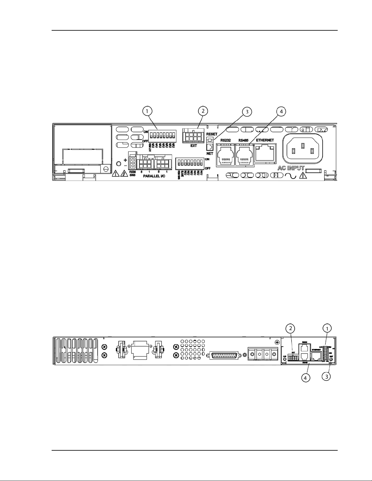
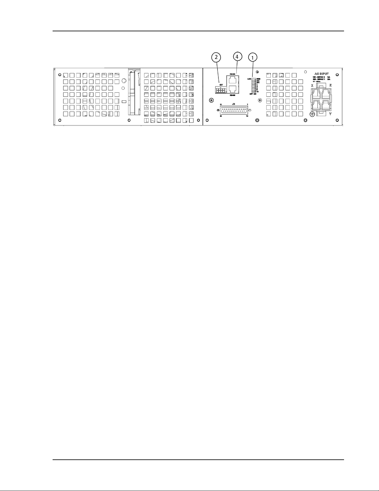
Figure 2-2. Typical Rear Panel of M130 Ether net O ption for DLM600
1 – Configuration Switch (for cor rect settings see Section 2.2.3)
2 – External User Control Signal Connector (see Section 2.3)
3 – Reset switch and green dual-purpose NET LED.
Reset switch (must be depressed until NET LED begins blinking, which could tak e
five or more seconds) returns configuration parameters to factory default settings
(see Section 1.3.2).
NET LED: when solid-lit, indicates Network Connectivity; blinking indicates
Instrument ID (See “Inst rument ID” under Settings, Section 2.4.4). If t he LED is
off, there is no Ether net c onnection found by the power supply.
4 – Connections for Ethernet (RJ-45) with built-in 10/100 indicator (on right top of the
RJ45 connector) and an Activity indicator (on the left top). Also RJ-11 connectors
for RS232 and RS485.
Figure 2-3. Typical Rear Panel of M130 Option for DCS1k and DCS1.2k
M130/M131 Programming Manual 2-5
Page 24
Configuration Sorensen Ethernet Option
Figure 2-4. Typical Rear Panel of M130 Opt ion for DCS3k
2.2.2 M131 (SLAVE) OPTION
Figure 2-5 through Figure 2-7 display the pertinent rear panel components of a
typical M131 Ethernet option for the DLM600 and the DCS slaves.
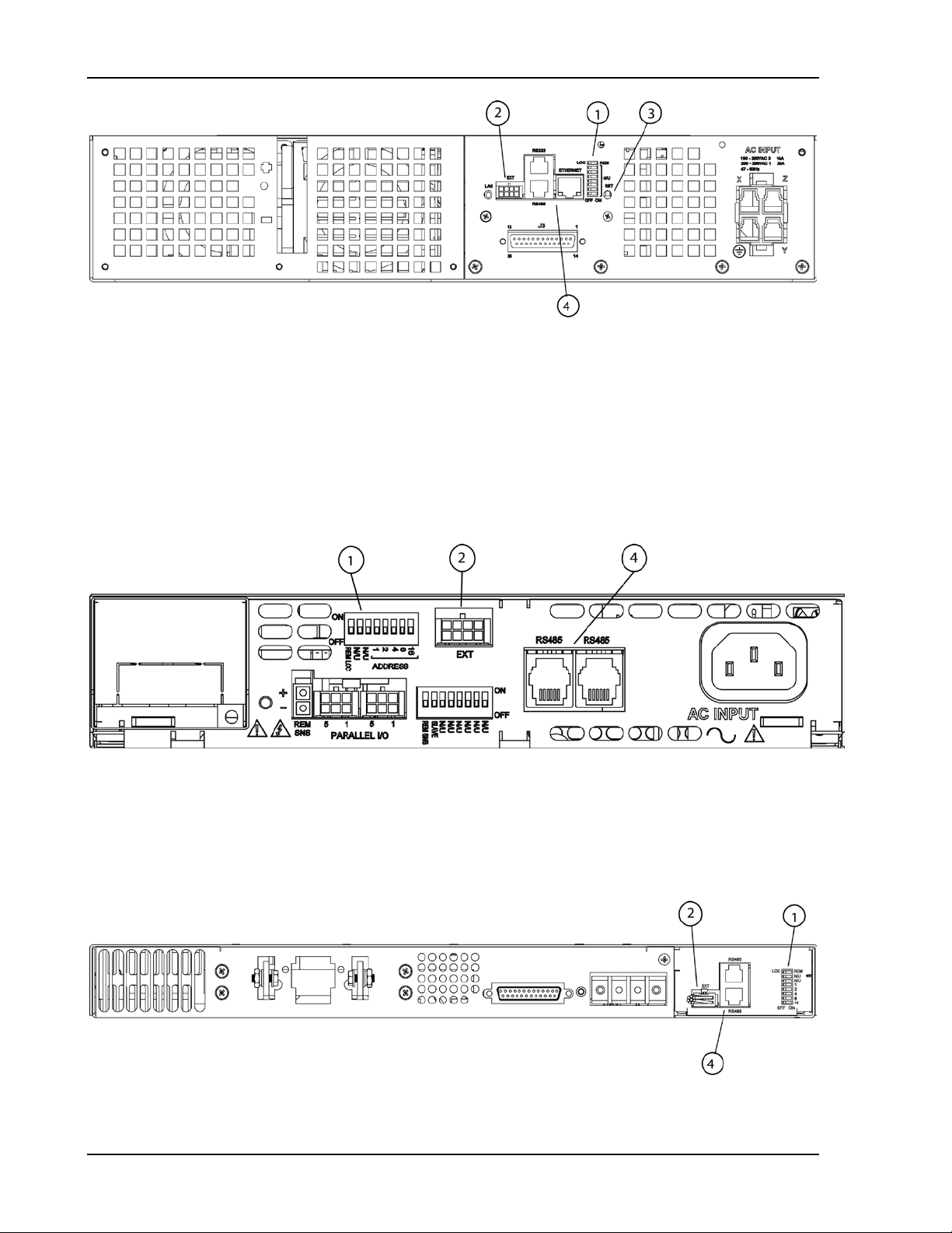
Figure 2-5. Typical Rear Panel of M131 Ether net O pt ion for DLM600
1 – Configuration Switch (for cor rect settings see Section 5.2)
2 – External User Control Signal Connector (see Section 2.3)
4 – Connections (RJ-11) for RS485
Figure 2-6. Typical Rear Panel of M131 Ether net O ption for DCS1k and DCS1.2k
2-6 M130/M131 Programming Manual
Page 25
Sorensen Ethernet Option Configuration
Figure 2-7. Typical Rear Panel of M131 Ether net O ption for DCS3k
M130/M131 Programming Manual 2-7
Page 26
Configuration Sorensen Ethernet Option
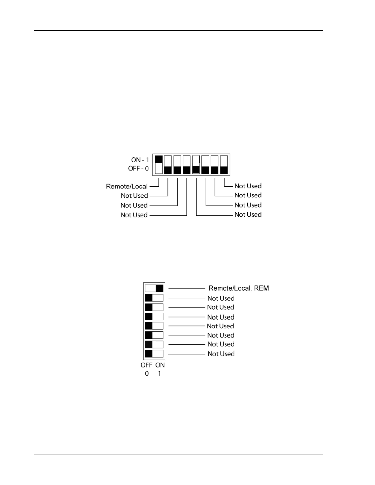
2.2.3 CONFIGURATION SWITCH
Use the DIP switch, accessible from the rear panel, t o c onfigure the power supply
with the installed M130/M131 for the particular system and application in use. The
following figures show the DIP switch configur ation for the M130, as set up in
Section 2.1 (see Section 5.2 f or the M131).
Note: On the Ether net master, the rear panel swit c h get s set to Remote On, and all
remaining switches are disregarded.
Note: Two types of DI P switches are utilized; toggle and rocker. For toggle
switches, the shading indicates the position of the toggle switch. For rocker
switches, the shading indicates the depressed side.
Figure 2-8. DLM 600W Configuration Switch for the M130 Option
Figure 2-9. DCS Configuration Switch f or t he M130 Option
2-8 M130/M131 Programming Manual
Page 27

Sorensen Ethernet Option Configuration
Local operation selected.
operation upon the first Ethernet , or RS-232 command.
0 Volts (initial from factory power–on voltage);
See CAL:INIT:VOLT to chang e.
0 Amps (initial from fac t or y power–on current ) ;
See CAL:INIT:CURR to change.
Model maximum voltage +10% (initial from fact ory
See CAL:INIT:VOLT:PROT to change.
2.2.4 REMOTE/LOCAL SELECTION
Set the rear panel Remote/Local switch to select remot e or local operation.
Table 2-1 Remote/Local Switch
Switch Position
ON Remote operation selected.*
OFF
* In the ON position, the power hardware and Ethernet card initialize to the remote state
at power-on. In addition, front panel cont r ol r em ains disabled regardless of the state of
the REN line, or the GTL command. T he spec ial SCPI command SYST[n]:LOCAL
<on/off> is now permitted as a m eans to revert to front panel contr ol if desired.
Powering up in remote mode will result in the following operating conditions.
Table 2-2 Remote Mode Power-on Conditions
Condition Default
Voltage
Description
Front panel control is enabled. Unit will switch to remote
otherwise, last value saved by SCPI command or by the
SAVE SETTINGS button in the Web Settings page.
Current
Soft Voltage Limit Model maximum voltage
Soft Current Limit Model maximum current
OVP Trip Voltage
Delay 0. 5 sec onds
Foldback Protection OFF
Output ON
Hold OFF
Unmask NONE
Service Request Capability OFF
M130/M131 Programming Manual 2-9
otherwise, last value saved by SCPI command or by the
SAVE SETTINGS button in the Web Settings page.
power–on OVP); otherwise, last value saved by SCPI
command or by the SAVE SETTINGS button in the Web
Settings page.
Page 28
Configuration Sorensen Ethernet Option
For RS-232/GPIB: FOLDBACK output signal, open collector,
Reserved function for Ethernet interface.
FAULT output signal, open collector, active-low.
Asserted when a fault is recorded in the fault register.
POLARITY output signal, relay contacts. Asserted (contacts close
(e.g., SOURce:VOLTage -5.0)
ISOLATION output signal, relay contacts. Asser t ed ( cont acts close
(e.g., OUTPut:ISOlation OFF)
SENSE output signal, relay contacts. Asserted (contacts close t o
(e.g., OUTput:SENse OFF)
SHUTDOWN TTL input signal, active-high. Allows the user to
immediately shutdown the unit by a TTL input signal.
For RS-232/GPIB: SYNC output signal, open collector, active-low.
function for Ethernet interface.
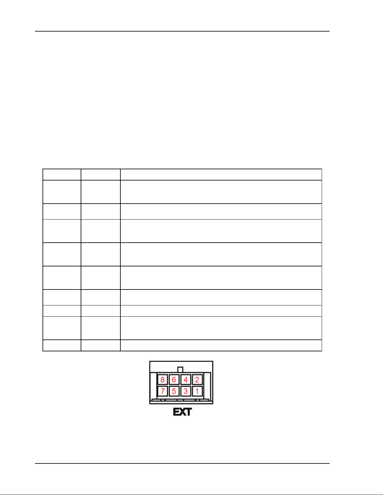
2.3 EXTERNAL USER CONTROL SIGNAL CONNECTOR
An 8-pin Molex connector located at the rear panel provides external auxiliary control
signals to increase the user’s operating control of the supply. The mating r eceptacle is
Molex 43025-0800 with 8 female terminals 43030-0003. The Molex terminals
accommodate wire sizes from #20 - #24.
The relay outputs, when active, connect the POLARITY, SENSE, and I SO LAT ION
pins of the connector to the relay COMMON pin. The relays are rated at
120VAC/125VDC @ 1A; for DLM600 Series 600W, m aximum r at ings are 60V(PK),
30VA, and 1A. For DCS 1k, 1.2k, and 3k, the maximum ratings are 250V @ 8A. Any
change in output (voltage, current , etc.) initiated by the user fr om t he RS-232, GPIB,
or Ethernet interface will generate a 10m s synchronization pulse at the rear panel
User Control Signal Connector of the master unit (Sync Signal).
Table 2-3 External User Control Signal Connect or Pi nout
Molex Pin Description
1
3
6
7
8
2
5 COMMON for all signals and relay contacts.
4
active-low. Asserted when in foldback mode.
to COMMON) when a negative voltage is progr ammed.
to COMMON) when the output relay is progr ammed OFF.
COMMON) when the sense relay is programmed OFF.
Pulsed for 10 ms when a change in the output occurs. Reserved
Figure 2-10. External User Connector Designati on ( 8-pin Molex)
Viewed from Rear Panel of Unit
2-10 M130/M131 Programming Manual
Page 29
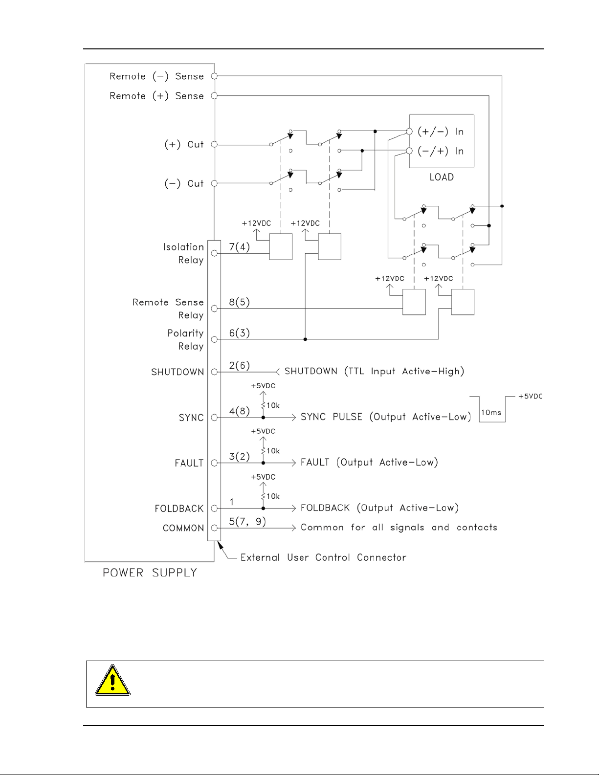
Sorensen Ethernet Option Configuration
Figure 2-11. Example of Open Collect or , TTL Input, and Relay Output Circuit s
CAUTION
The relays must not be hot-switched; ensure that the voltage across the relay
contacts and the current thr ough them is zero prior to changing the relay states.
M130/M131 Programming Manual 2-11
Page 30

Configuration Sorensen Ethernet Option
2.4 PROGRAMMING VIA ETHERNET
2.4.1 COMMUNICATION METHODS
With the M130 option, there are four basic methods to com municate with the power
supply from a PC:
• raw socket interface, sending delimited strings ( default delimiter is
<LineFeed>)
• application program that utilizes VXI-11 Discovery protocol
• Web browser and the internal Web server, with scripting of Java applets
enabled
• RS232C serial interface
2.4.2 RAW SOCKET INTERFACE
The essential components of comm unicat ing via a raw socket interface are the
socket number, IP address and c om m and delimit er . The default values are: socket =
9221, IP address = 192.168.0.200 (when static IP is enabled), and delimiter = line
feed <LF>. All of these item s m ay be chang ed eit her via the Web browser (see IP
CONFIGURATION, p. 2-16) or RS232C interfaces (see SCPI com m and sec t ion) .
For convenience and to comply with the proposed LXI™ standard, the VISA
resource name is available on the home page of the power supply’s Web server.
2.4.3 VXI-11 PROTOCOL
With programs such as Agilent’s I/O Libr ar y Suite, or Nat ional Instrument’s NI-VISA,
the VXI-11 protocol allows the power supply to be easily configured in a test system.
2.4.4 WEB SERVER
To communicate with the power supply via the built-in Web s er ver, open a suppor ted
Web browser (Internet Explorer 6.0 or higher) and type the I P address of the power
supply in the “Address” field. Tap the
Ethernet W eb page interface.
Note: To ensure proper functionality on your Web browser, Sun Microsystems’
Java Runtime Environment must be installed on your PC. Vis it
www.java.com to download. Also, set your Web browser’s Security to enable
scripting of Java applets. (In the Tools menu, select Internet Options… and
click the Security tab. At the bottom of the Security window click Custom
level…; in the Reset custom settings drop-down, select Medium and click
Reset and then OK).
ENTER key to launch the power supply’s
2-12 M130/M131 Programming Manual
Page 31

Sorensen Ethernet Option Configuration
Ethernet Web Pages, Overview
The layout of each of the Web pages includes the banner with the heading ,
“Sorensen DLM (or DCS) Power Supply Interface” along with the device name
below and a LOGIN button to the right. Below the banner are s ix tabs, each link ed
to its corresponding page. O n each page is a title line (title matches tab name) . I n
the title line is an area that freq uent ly displays inform at ional mes sages as you use
the Web inter face.
When navigating t o t he Et hernet Web pages by clicking their tabs, you will find
that only two of the pages may be accessed without logging in: HOME (def ault )
and SLAVE INFO; you must log in (click LOGIN) before tabbing to the other
pages, which allow access by permission only: FULL (Administrator), RW
(Read\Wr it e) , or R ( Read) .
• FULL permissions users have access to all pages and all channels and
may configure the interf ac e, set and change security settings, allocate
channels, control the output of t he power supply, send commands, etc.
• RW permissions users may access all pages except SECURITY, and m ay
read and control the output of t he power supply for only the channels
allocated to them. They are not authorized to make changes on the IP
CONFIGURATION page.
• R permission users may read information related only to the channels
allocated them, and cannot make any changes or control the output.
Once you have logged in, the LOGIN button becom es a LO GOUT button.
Note: There are few differences between the DCS interface and the DLM
interface: their titles and device names in the banner ( s ee Figure 2-12 and
Figure 2-13), their specif ics in t he Hom e page (see Figure 2-15 and Figure
2-16), and the front panel lockout button in the Settings page ( see Figure 2-19)
is grayed out for the DCS products. Unless DCS and DLM interfaces ar e bot h
shown, the following illustrations use only the DLM interface.
Figure 2-12. DLM Web Page Banner
Figure 2-13. DCS Web Page Banner
M130/M131 Programming Manual 2-13
Page 32

Configuration Sorensen Ethernet Option
Figure 2-14. Login Window
HOME
This is the default, infor m ation-only page. It displays all of the current information
about the master supply that you are connected to (if any slaves are connected,
their information is on the
SLAVE INFO page):
Figure 2-15. DLM Home Page
2-14 M130/M131 Programming Manual
Page 33
Sorensen Ethernet Option Configuration
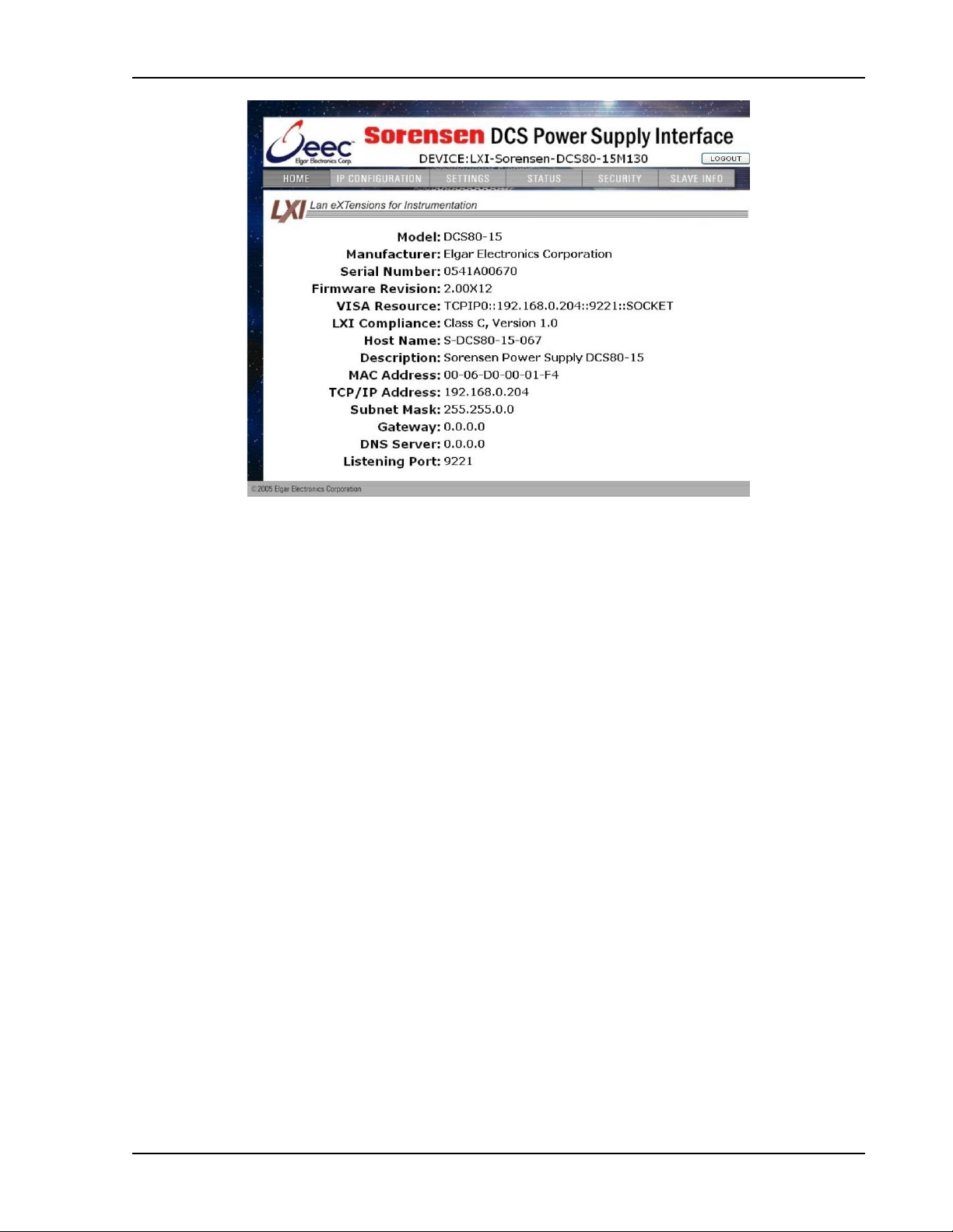
Figure 2-16. DCS Home Page
• The Model number, the Manufacturer, and t he Ser i al Num ber of your
Ethernet power supply
• Firmware Revision: the version of the Ether net firmware that is currently
installed for the Master. (See SLAVE INFO page for slave firmware
version.
• VISA Resource identifies the specific resource name used to
communicate via VISA (Virtual Instrument Software Architecture)
• LXI™ Compliance: the version and instrument class of the LXI™
standard with which your power supply is compliant
• Host Name: either the default or user-defined, network-unique identity
• Description: either the default or user-defined description of the power
supply in use (you can change the description to suit your needs, in the
CONFIGURATION page)
• MAC Address: the power supply Ethernet’s unique hardware address
• IP Address: your power supply’s address actually in use at start-up; can
be statically configured, DHCP acquired (default), or Auto-IP assig ned
(see description for
CONFIGURATION page)
• Subnet Mask: network segment your power supply is on
• Gateway: IP address through which the instrument com m unicat es with
systems that are not on the local subnet
• DNS Server: IP address of t he Dom ain Name System (DNS) server
• Listening Port: port number for the em bedded Web server
M130/M131 Programming Manual 2-15
Page 34

Configuration Sorensen Ethernet Option
IP CONFIGURATION
Only users with FULL permissions shall have access to this Web page and be
allowed to configure the interface. You ar e only req uired to complete the
information for the parameters that you wish to change; all previously entered
and saved information remains the by default.
Figure 2-17. DLM IP Configuration Page
Figure 2-18. DCS IP Configuration Page
2-16 M130/M131 Programming Manual
Page 35

Sorensen Ethernet Option Configuration
• Host Name: the default name includes the base model number of your
power supply, with the last four digits of the ser ial number . You m ay
change this name as long as it is unique so that VX I-11 Discovery and any
other IP Discovery program can identify your specific device on your
network.
To change: Type the new name (15 characters maximum) in
the blank field provided and click Apply to update
(or make all desired changes before clicking
Apply).
• Description: you may change the default factory sett ing to something
more meaningful to your current s et up.
To change: Type your customized description, up to 64
characters, in the blank field provided, and click
Apply to update (or make all desired changes
before clicking Apply).
TCP/IP Configuration: the power supply has two TCP/IP configurations that can be set , Primary and Secondary. If the Primary Configuration is not valid on your network, the power supply will attempt to try the Secondary Configuration.
NOTE: The power supply will NOT try the Secondary Configuration if you have selected the Primary Configuration options, Obtain an IP Address Automatically and Auto IP Enabled.
You may statically assign an IP address as well as configure ot her Ethernet/LAN parameters, or you may keep/return to its default setting for automatic assignment of an IP addres s.
To assign: Click the radio button next to Use a Static IP
Address to manually configure some or all of the
following the Ethernet/LAN parameters:
IP Address – input any standard IP address.
(Factory setting is 192.168.0.200). After clicking
Apply, you also must reset the power supply and
then exit and restart the W eb browser to effect this
change. If you have changed the network portion of
the IP address, it may be necessary to alter the
network settings of your attached computer to
reconnect to the power supply.
Subnet Mask – input a value that identifies which
network segment your power supply is on, consisting
of 4 whole numbers, each ranging from 0 through
255, separated by periods. (Factory setting is
255.255.255.0, a class-C network subnet mask).
Click Apply to update (or mak e all desired changes
before clicking Apply).
Gateway – input the IP Address of any gateway that
stands between the instrument and any other
M130/M131 Programming Manual 2-17
Page 36

Configuration Sorensen Ethernet Option
network entities that communicate with the power
supply. (No factory setting). Click Apply to update (or
make all desired changes before clicking Apply).
DNS Server – input an IP address for the Domain
Name System (DNS) server. Click Apply to update
(or make all desired changes bef ore clicking Apply).
This field has no factory sett ing .
Listening Port – input a port number for the
embedded Web ser ver, ranging in value from 1025 –
65535. Click Apply to update (or make all desired
changes before clicking Apply). The factory default
port number is 9221.
To automate: (To return to the default setting): Click the radio
button next to Obtain an IP Address
Automatically for dynamic address acquisition
from the DHCP server.
Auto IP Enabled: allows the power supply to assign itself an IP
address in the range from 169.254.0.1 to
169.254.255.254 with a subnet mask of 255. 255.0.0.
If it is enabled, when there is no DHCP server
available, the power supply will assign itself an IP
address. However, please keep in mind that when
you select Obtain an IP Address Automatically and
you check Auto IP Enabled in TCP/IP Primary
Configuration, the system will not try the Secondary
Configuration.
To enable: Click in the box to check; click again to uncheck so
that it is no longer enabled.
Example TCP/IP Configurations:
Primary: Use a Static IP Address
Secondary: Obtain an IP Address Automatically (DHCP)
At power-up the power supply will assign itself the configured static IP address. If
no other device is using the IP address, the power supply continues with that
static IP address. If some other device is using that address, the power supply will
move to Secondary and attempt to acquire an IP address from a DHCP server
repeatedly until it gets an address.
Primary: Use a Static IP Address
Secondary: Obtain an IP Address Automatically (DHCP) and AutoIP Enabled
At power-up the power supply will assign itself the static IP address. If no other
device is using the IP address, the power supply continues with that static IP
address. If some other device is using that address, the power supply will move to
secondary and attempt to acquire an IP address from a DHCP server. If it cannot
find a DHCP server to assign an address, it will assign itself a link-local address.
If no other device is using that link-local address it will use it for 5 minutes
minimum. At that time, if it is already in communication with some other device, it
will hold onto that link-local address until the communication is finished and then
retry DHCP. Then, if DHCP is not available, the power supply will revert to the last
successful link-local address for another 5 minutes minimum.
2-18 M130/M131 Programming Manual
Page 37

Sorensen Ethernet Option Configuration
Primary: Obtain an IP Address Automatically (DHCP) and AutoIP Enabled
Secondary: no matter the setting, will never be attempted
At power-up the power supply will attempt to acquire an IP address from a DHCP
server. If it cannot find a DHCP server to assign an address, it will assign itself a
link-local address. If no other device is using that link-local address, it will use it
for 5 minutes minimum. At that time, if it is already in communication with some
other device, it will hold onto the link-local address until the communication is
finished and then retry DHCP. If DHCP is not available, the power supply will
revert to the last successful link-local address for another 5 minutes minimum.
Primary: Obtain an IP Address Automatically (DHCP)
Secondary: Use a Static IP Address
At power-up the power supply will attempt to acquire an IP address from a DHCP
server. If it cannot find a DHCP server to assign an address, the power supply will
move to Secondary and assign itself the static IP address. If no other device is
using the IP address, the power supply continues with that static IP address. If
some other device is using the static IP address, the power supply will move back
to Primary and start the entire operation again
SETTINGS
The Settings page is available to users who have FULL, Read/Write or Read
Only access to at least one power supply (Read Only users can make no
changes to the settings) . I f you have a system with a single master and many
slaves, you could have access to one or more individual power supplies in the
system (see SECURITY pages).
Figure 2-19. Settings Page
M130/M131 Programming Manual 2-19
Page 38

Configuration Sorensen Ethernet Option
• Selected Channel: selected power supply channel whose Settings are
presently displayed/updated (1= Master channel, and 2 – 31 = slave
channels); you can select a different c hannel to which you have access:
To select: Click and hold the drop-down button; you will see
only the channel numbers that you have rights to
access; click the desired channel number.
NOTE: If no channels are displayed, an
Administrator or a user with FULL permission (see
SECURITY, p. 2-24) must assign channel access
to the particular User ID, throug h the Security page
(Figure 2-22), using the ALLOCATE CHANNELS
capability.
Below Selected Channel you will see continuous updates (2-5 times per second) of the act ual voltage output (value displayed on the left) and the actual live current output (value displayed to the right).
• Voltage: value above is updated with actual voltage output of the power
supply
• Current: value above is updated with actual live current output
• Set V: the programmed voltage setting
• Set I: the programmed current setting
• Set OVP: the programmed over voltage protect ion set t ing
• APPLY: puts into effect the newly input settings
• CC and CV indicators: presently operating output mode of the power
supply, either constant voltage or constant cur r ent.
• OVP indicator: highlighted red if over voltage protection is activated
• FAULT indicator: highlighted red if fault has occurred
• OUTPUT indicator: solid-lit shows power output status is On
If you have Read/Wr it e acc ess, you can change the following settings (after inputting desired settings, click APPLY):
• Set V – click in the Set V field and input a new value for voltage.
• Set I: click in the Set I field and input a new value for current.
• Set OVP: click in the Set OVP field and input a new value for over
voltage protection.
Output – click the applicable button(s) as follows:
• CLEAR OVP: to clear the OVP indication/condition after clearing the
cause of the event. The power supply will revert to the last saved values
for Voltage, Current, and OVP. Be sure to reset these values, if desir ed,
before clearing an OVP condition.
2-20 M130/M131 Programming Manual
Page 39

Sorensen Ethernet Option Configuration
• CLEAR FAUL T: t o clear t he har dware fault indication/condition after
clearing the cause of the event.
• OUTPUT: to turn on or off the power output (see Output indicator)
• FRONT PANEL LOCKOUT: to prevent or enable changes being made
via the front panel (LED to the left is lit when Lockout is in effect).
• INSTRUMENT ID: click to identify which power supply (instrument) in a
rack of equipment c or r esponds t o the Channel selected. The LED to the
left of this button indicat es whether or not this function is turned on (ON
causes the instrument’s rear panel NET LED to flash; the flashing
continues until you click INSTRUMENT ID again).
Power-on Default: click the applicable button(s) as follows:
• RECALL SETTINGS: click to restore the programmed Power-on defaults
into the Set V, Set I and Set OVP setting s , and t o the power supply
output (these defaults are t hos e t hat were last saved prior to this Poweron).
• SAVE SETTINGS: after clic king APPLY, click to save the presently set
values displayed in the Set V, Set I and Set OVP fields into non-volatile
flash. (If only one new setting had been input , the other previously saved
values remain the same). Please be awar e t hat these then become the
new power-on settings that w i ll be applied at pow er-up t ime and
after OVP reset as described in “Clear O VP” above.
NOTE: When you click SAVE SETTINGS, you will get a pop-up alert
Figure 2-20) telling you that saving a non-zero voltage may cause the power
(
supply to power-on with a voltage on its out put t er minals after a restar t or
power cycle.
Figure 2-20. Alert Message for Save Settings
SCPI command section:
• SEND COMMAND: (not to be used with any command that provides a
response) input a properly formatt ed SCPI com mand in the upper of the
two win dows and click this button to send the comm and.
• SEND AND READ: for queries, input a properly format ted SCPI query
command in the upper of the two windows, and click this button to send
the command and read the response in the lower of t he t wo windows.
• SCPI Command History: a history of the last few commands sent to t he
power supply are remembered by the system and listed in this area. You
can click on a command to have it be pasted in the command window.
M130/M131 Programming Manual 2-21
Page 40

Configuration Sorensen Ethernet Option
• CLEAR RESPONSES: click this button to clear t he r es ponse window of
previous responses.
STATUS
This page displays updated information f or the following parameters:
Figure 2-21. Status Page
• Selected Channel: as in the Settings page, this is the selected power
supply channel whose information is presently displayed/updated
(1= Master channel, and 2 – 31 = Slave channels); you can select a
different channel to which you have access:
To select: Click and hold the drop-down button; you will see
only the channel numbers that you have rights to
access; highlight the desired channel number and
release the mouse button.
NOTE: If no channels are displayed, an
Administrator or a user with FULL permission (see
SECURITY, p. 2-24) must assign channel access
to the particular User ID, throug h the Security page
2-22 M130/M131 Programming Manual
Page 41

Sorensen Ethernet Option Configuration
(Figure 2-22), using the ALLOCATE CHANNELS
capability.
• Output: displays the power output status, ON or OFF
• Trigger: set up by SCPI commands, displays whether the Trigger state is
OFF, ARMED, or TRIGGERED.
• OVP: displays Read Only status of over voltage protection, either OK
(normal) or TRIPPED.
• OTP: displays Read Only status of over temperature condition, eit her O K
(normal) or TRIPPED.
• Command Error: displays command and syntax errors that are queued
in the supply.
• Read Next Error: each click brings the next error into the Command
Error display, until no other errors are in the q ueue.
• CLEAR MESSAGES: click this button to clear the Command Error
message window of past messages.
• Last Calibration Date: displays the date that the power supply
(instrument) was last calibrated; configurable with SCPI commands,
normally at the time of calibration.
• Next Calibration Date: displays the date that the power supply should be
calibrated next; also configurable with SCPI commands, nor m ally
calculated at time of calibration.
• Ping Echo: except for Read Only users, allows turning echo ability On or
Off, depending on whether or not you want the supply to respond to a
Ping command from another device on the net work . The default setting
for Ping Echo is response enabled. Click the O FF r adio but t on if you do
not want the supply to respond to a ping.
• Ping Remote IP Address: allows you to input an IP address of another
device in the system
• Ping: click this button to ping the device at the address t hat you enter ed
in the Ping Remote IP Address field.
• Response: displays the result of your ping. For Example, if the Ping
Address were 69.36.230.190, the Response window would display:
Pinging :69.36.230.190 Response Took 0 ticks
Or
Ping Failed (if the host specified is not in t he net work )
• CLEAR RESPONSES: click this button to clear t he Response window of
past ping responses.
M130/M131 Programming Manual 2-23
Page 42

Configuration Sorensen Ethernet Option
SECURITY
Accessible only if you have Administrative (Full) rights, this page allows you to set up new user accounts for access to t he power supply(s). It displays all of the currently set up users and respective permission levels.
• FULL = full rig hts/Administrator
• RW = read and write to power supply(s)
• R = Read Only
• -L = identif ies user currently logged onto a power supply session.
Figure 2-22. Security Page
• ADD: Click to pull up a separate page in which to input new users with
passwords and permission levels. (See Figure 2-23).
• REMOVE: Click to delete selected user after first highlighting their User
Name row. The Admin user cannot be removed.
• EDIT: Click to change settings (name/perm iss ions) for selected user after
first highlighting t heir User Name row. This brings up the Edit Existing
User window (Figure 2-24).
• Allocate Channels: click to pull up the Channel Allocation page, which
presents a matrix of all users and all possible power supply channels,
whether they are in the system or not. (See Figure 2-25).
2-24 M130/M131 Programming Manual
Page 43

Sorensen Ethernet Option Configuration
ADD NEW USER
Accessible from the Security Page by clicking t he ADD butt on, this page is allows you (a Full permissions user) to add new users with their passwords and permission levels.
Figure 2-23. Add New User Window from Security Page
To add: 1. Input appropriate information in User ID (case-sensitive, limited
to 14 characters), in Password (case sensitive, limited to 9
characters), and in Re-enter Password fields.
2. Select permission level from the Permission dropdown.
3. To accept into the system, click SUBMIT or tap the
ENTER key.
In the ADD NEW USER: line, you will see a message that the [ new user name] was added successfully, or a message that it was unsuccessful and the reason.
NOTE: In order to complete t he addit ion of a new user, you must also allocate channels to that user. (See CHANNEL ALLO CATION, p. 2-27).
RESET clears the fields in which you input information.
CANCEL returns you to the Security page. This button does NOT “ undo”
previous successful submit operations.
M130/M131 Programming Manual 2-25
Page 44
Configuration Sorensen Ethernet Option
EDIT EXISTING USER
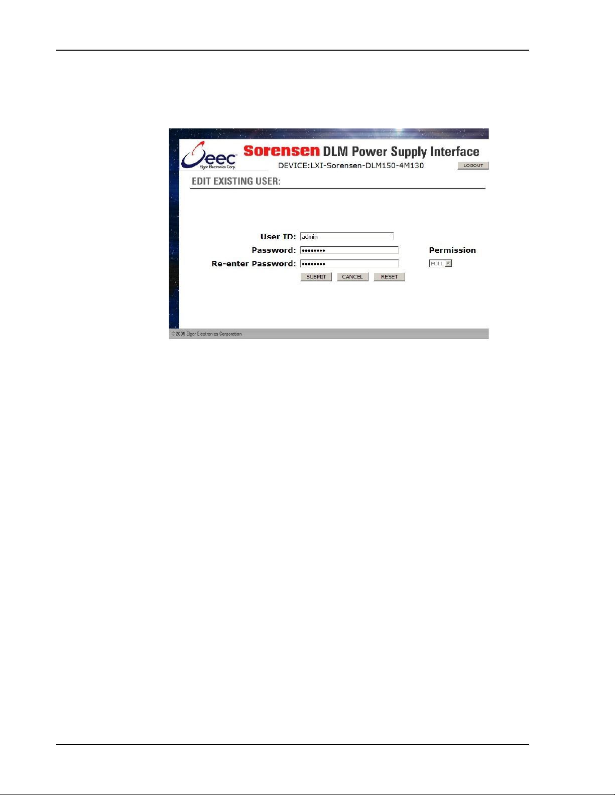
Accessible from the Security Page by clicking t he EDIT button after first selecting the user’s name, this page allows you (a Full permissions user) t o edit the parameters for an existing user .
Figure 2-24. Edit Existing User Wi ndow from Security Page
When this pag e appear s , the fields are populated with the selected user’s existing parameters.
To edit: 1. Input appr opr iat e information, as desired, in User ID (case-
sensitive, limited to 14 characters), in Password (case
sensitive, limited to 9 characters), and/or in Re-enter Password
fields.
2. Select permission level from the Permission dropdown.
3. To accept into the system, click SUBMIT or tap the
ENTER key.
If your edit was successful, you will return to the Security pag e with a message to that effect .
If there is an error in the edit ing process, you will stay in the Edit Existing User page, and you will see a message in the EDIT EXISTING USER: line, desc r ibing the reason for the error .
RESET clears the fields in which you input information.
CANCEL returns you to the Security page with a message verifying that the User
Edit was cancelled.
2-26 M130/M131 Programming Manual
Page 45

Sorensen Ethernet Option Configuration
CHANNEL ALLOCATION
Accessible from the Security Page by clicking t he ALLO CAT E CHANNELS button, this page is allows you (a Full permissions user) to select a user and select the power supply(s) to which that user shall have access.
Figure 2-25. Channel Allocation Wi ndow from Security Page
X indicates which power supply (channel) each user has access to.
Because an Administrator has full rights to all functions of the
power supply(s), a user with FULL permissions has access to all
channels regardless of whether the Channel Allocation page
indicates he has permissions or not.
To change: 1. Select a user from t he Sel ect ed User drop-down,
and check or uncheck the boxes above the
desired channel numbers.
2. Click Accept. Repeat for each user for whom you are changing/allocating channels.
3. W hen finished, click Done to return to the initial Security page.
M130/M131 Programming Manual 2-27
Page 46

Configuration Sorensen Ethernet Option
SLAVE INFO
This page displays information only for the power supplies configured in this
system (one master power supply with a single IP address and up to 30 slave
power supplies – M131 and/or M85). The information for each power supply
displayed includes the Channel number (1 is the Master; 2 through 31 are
Slaves), the model number, the serial number, and t he firmware revision.
Figure 2-26. Slave Informati on Page
Upon first entering this pag e, you will see information only for the slaves with
which the master established communication during the pr esent session. Click
REFRESH SLAVE DATA to see the information on the remaining slaves present
in this system. (This refr esh operation could take up to 60 seconds).
2-28 M130/M131 Programming Manual
Page 47

Sorensen Ethernet Option Configuration
2.4.5 TROUBLESHOOTING
Resetting IP Configuration
Either press and hold in the IP reset switch (S2) on the rear panel until the green
NET LED flashes (this could take 5 or more seconds), which resets the Primary
configuration to DHCP and AutoIP Enabled (and ig nor es Secondar y
configuration), or send t he SCPI c om m and, SYST:NET:IP xxx.xxx.xxx.xxx
through one of the f ollowing: t he RS-232, the Server, or VXI-11. This sets the
primary configuration to Stat ic I P, and t he s econdar y configuration is left where it
presently is.
Cannot Establish Communication
Use RS232 port. Note 19.2k baud rate at J6.
Query IP address with the SCPI command, SYST:NET:IP?
Query the MAC address with the SCPI command, SYST:NET:MAC?
For Slave (M131) communication issues, check the slave unit address switch
setting.
Communication Established, but No Power Supply Response
Check SCPI string for er r ors (use the command SYST:ERR? to check response from unit)
Web Page Does Not Come Up
Check IP address; validate your SUBNET Mask.
Verify that both your computer and the power supply are on the same net work.
If using a direct connection with a crossover cable, verify the PC is set to static
IP address on the same network.
Observe the indicator LED on Ethernet port (J11) for activity. The NET LED (at
rear panel center, near IP reset switch) will be lit when communication is
established.
Lost/Forgot Password
If you are a user, contact t he Administ r ator of the power supply network to modify your password.
If you are the administrator, t he only way to recover is to press and hold the I P
reset switch on the rear panel until the Green NET LED blinks ( t his could t ake
five or more seconds). The administ rator User Name and password will be
restored to factory defaults, as will the IP Address, the IP Addressing Mode, Ping
Enable, SUBNET Mask, Host name, and Description String. All other defined
user names and passwords are not aff ect ed by the r eset operation.
M130/M131 Programming Manual 2-29
Page 48

Configuration Sorensen Ethernet Option
2.5 REMOTE PROGRAMMING VIA RS-232
The M130’s RS-232 interface operates at 19.2K baud with 8 data bits, no par it y, and 1
stop bit. All M130 commands are supported at the RS-232 interface. The RS-232
interface is accessible through t he power supply’s rear panel 6-p in RJ-11 connector,
labeled RS232(485).
Figure 2-27. RS-232 Rear Panel RJ-11 Connector Pinout
Figure 2-28. M130 to PC RS-232 Connecti on ( RJ-11 t o DB-9)
2-30 M130/M131 Programming Manual
Page 49

Sorensen Ethernet Option Configuration
2.6 EXTENDED INTERFACE BUS (EIB) WITH THE M131
OPTION
The M130 Master unit communicates with up to thirty M131 Slave units via a RS-485 serial
interface port on rear panel. To connect a M130 Master to a M131 Slave, insert a 6-conductor
serial cable (with male RJ11 connectors at both ends) between the RS-485 ports on the Master
and Slave units. Additional Slave units can be "daisy chained" together via their respective
RS-485 ports. Please refer to the applicable power supply manual (DCS or DLM600) for more
detail.
Figure 2-29. EIB (RS485) Rear Panel RJ-11 Connector Pinout
Figure 2-30. M130 to M131 EIB Connection (RJ-11 to RJ-11)
M130/M131 Programming Manual 2-31
Page 50

Configuration Sorensen Ethernet Option
This page intentionally left blank.
2-32 M130/M131 Programming Manual
Page 51

3.1 INTRODUCTION
The following sections describe the operation of the M130 by remote
programming using the M130 IEEE-488.2 and SCPI c om m and sets. The supply
IEEE488.2 and SCPI command sets provide programm ing , query, and status
commands that facilitate r em ot e c ont r ol of the power supply.
SECTION 3
IEEE 488.2 AND SCPI
COMMAND OPERATION
3.2 IEEE-488.2 REGISTER DEFINITIONS
The M130 supports the IEEE-488.2 and SCPI 1995.0 status r epor ting data
structures. These structures are comprised of s t atus registers and status r egister
enable mask pairs. The following sections descr ibe t hes e pairs .
3.2.1 SCPI STATUS BYTE
• To read the SCPI Status Byte status register, eit her send the *STB?
command or issue a GPIB or Ethernet ser ial poll. T o clear t he St atus
Byte status register, send the * CLS com m and.
• To configure the supply to request service fr om the Ethernet controller,
set the appropriate bits in the Service Request Enable (SRE) register.
The SRE register has the same bit pat t er n as t he SCPI St at us Byte.
• To modify the SRE register, use the *SRE <mask> c om m and; to read it,
use the *SRE? command. For example, if the SRE reg ister is set to
0x10 (MAV), then when the supply has a message available, the Status
Byte register will contain 0x50 (RQS and MAV). See Table 3-1.
M130/M131 Programming Manual 3-1
Page 52

IEEE 488.2 and SCPI Command Operation Sorensen Ethernet Option
Bit
Hex Value
Description
0
0x01
Not used.
Protection Event Status flag. Indicates the selected protection
event occurred.
Error/event queue message available. Set when any error/event is
SYSTem:ERRor? query.
Questionable Status flag. I ndicat es t he quality of the current data
being acquired. This bit is not used.
Message available (MAV). Indicates a message is available in the
output buffer is read.
Standard Event Status Register (ESR). Summ ary bit for the ESR.
read.
Request Service flag (RQS) for serial polling or Master Summary
IEEE-488.1 Status Byte.
Operation Status flag. I ndicates the current operational state of the
unit. This bit is not used.
Table 3-1 SCPI Status Byte
1 0x02
2 0x04
entered in the System Error Queue. It is r ead us ing the
3 0x08
4 0x10
GPIB or Ethernet output queue. Cleared after the GPIB or Et her net
5 0x20
Set when any of the ESR bits are set and cleared when the ESR is
6 0x40
Status (MSS) in response to *STB? If ser vice req ues t s ar e enabled
(with the *SRE command), this bit represents the RQS and will be
sent in response to a serial poll, then cleared. If RQS is not
enabled, the bit represents the MSS bit and indicates the device
has at least one reason to request ser vice. Even thoug h t he device
sends the MSS bit in response to a status query (*STB?), it is not
sent in response to a serial poll. It is not considered part of the
7 0x80
3.2.2 STANDARD EVENT STATUS REGISTER (ESR)
• To read the Standard Event Status Register (ESR), use the *ESR?
command.
• To clear the ESR, either read this register or issue the * CLS comm and.
• To enable corresponding ESR bits to be summarized in the summary bit
of the SCPI Status byte, issue the *ESE (Standard Event Status Enable
Register) command.
3-2 M130/131 Programming Manual
Page 53

Sorensen Ethernet Option IEEE 488.2 and SCPI Command Operation
Bit
Hex Value
Description
0
0x01
Operation Complete
1
0x02
Request Control - not used
2
0x04
Query Error
3
0x08
Device Dependent Error
5
0x20
Command Error (e.g., syntax error)
7
0x80
Power On
0
0x01
Constant voltage operation
2
0x04
Not used
Table 3-2 Standard Event Status Register
4 0x10 Execution Error ( e.g., range err or )
6 0x40 User Request - not used
3.2.3 PROTECTION CONDITION AND PROTECTION EVENT STATUS REGISTERS
These two registers have the same bit meaning s, but they differ in f unction.
• To read the Protection Condition, use the STAT:PROT:COND?
command. This command gives the pres ent status condition of the
power hardware, so the data is not latched. It is a polling reg ist er.
• To read the Protection Event Status, use the
STATus:PROTection:EVENt? command. To clear the Prot ec t ion Event
Status Register, either read t his r egister with the *RST command, or
issue the *CLS command.
• To set bits in the Protection Event Status Register, you must first set the
corresponding bit in the Protection Event Status Enable Register and
the corresponding event must occur.
• To set the Enable Register, issue the STATus:PROT ec t ion: ENABle
<mask> command. T he status is then latched and will remain in that
state until it is read or cleared due to some command action. Then use
the STATus:PROTection:ENABle? quer y to r ead t he Enable Reg ist er .
Table 3-3 Protection Condition and Event St at us Regi st er s
Bit Hex Value Description
1 0x02 Constant current operation
3 0x08 Overvoltage protection tripped
4 0x10 Overtemperature protection tripped
5 0x20 Supply external shutdown active
6 0x40 Foldback mode operation
7 0x80 Remote programming error
M130/M131 Programming Manual 3-3
Page 54

IEEE 488.2 and SCPI Command Operation Sorensen Ethernet Option
Error Code
Description
208
Isolation relay must open first
state of the polarity relay.
207
Voltage sign mismatched polarit y relay state
algebraic sign also can cause this error.
206
No channels setup to trigger
trigger setting s.
205
GPIB or Ethernet GET not allowed during message
transfer over the GPIB or Et hernet.
3.2.4 OPERATION STATUS AND QUESTIONABLE STATUS REGISTERS
The Operation Status and Questionable Stat us Reg ist ers will always return 0
when queried. The Operation Status Enable and Questionable Status Enable
Registers can be programmed and queried to allow SCPI compatibility but have
no effect on the Oper at ion St at us and Q uestionable Status Registers.
3.2.5 ERROR/EVENT QUEUE
The supply maintains an Error/Event Queue as defined by SCPI. The queue
holds up to 10 error events.
To view the error events, use the SYSTem:ERRor? Query command, which
reads in a First In/First Out ( FI FO) manner. The read operation r em oves the
entry from the queue. The *CLS command clears all entries fr om the queue.
The following error codes are def ined in the SCPI 1995. 0 s pecification and are
supported by the M130. Error codes are in the range of [-32768, 32767]. SCPI
reserves the negative error codes and 0, while error codes g r eater than 0 are
device-specific errors.
Table 3-4 SCPI Error Codes
An attempt to change the st at e of the polarity relay was made while the
isolation relay was closed. First open the isolation relay; then change the
The algebraic sign on the voltage of a voltag e programming comm and,
such as SOUR:VOLT <volt>, did not match t he s t ate of the polarity relay,
so the voltage command was ignored. For example, if the polarity relay is
in the positive voltage position (normal output voltage position), t he
command SOUR:VOLT –5 will cause this error. Conversely, if the polar ity
relay is in the negative voltage position (inverted output voltage position),
the command SOUR:VOLT 5 will cause this error.
Note that programming O ver Voltage Protection with a mismatched
An attempt was made to trigger the M130 using the TRIG:TYPE <1|2|3>
command when there are no armed trigg er s et t ings. This error is not
generated when the GET is received, even when there are no armed
The GPIB or Ethernet G(r oup) E( xecute) T(rigger) mult iline comm and was
errantly generated by the system computer while or very shortly after a
3-4 M130/131 Programming Manual
message is or was sent. Give a few milliseconds after a m es sage is sent
before attempting a G ET; and never send a GET during a message
Page 55

Sorensen Ethernet Option IEEE 488.2 and SCPI Command Operation
Error Code
Description
204
GPIB or Ethernet IFC caused w ar m boot
in association with a proprietary command.
203
Hardware w at chdog warm boot
error by a very momentary power-off through the front panel power switch.
202
Foreground watchdog warm boot
required.
201
Unexpected warm boot
processor.
102
Incompatible unit type
This error is not used. It cannot occur.
101
Incompatible unit version
query command.
100
Incompatibility error
This error is not used. It cannot occur.
0
No error
The error queue is empty.
-102
Syntax error
An unrecognized command or data type was encountered.
-108
Parameter not allow ed
More arguments than expected were received.
-151
Invalid string data
more than 16 characters. Invalid mnemonic.
-161
Invalid block data
The expected number of data values was not received.
-200
Execution error
device.
-203
Command protected
Attempted to store calibration values to EEPROM without unlocking.
This error relates to the G PI B or Et hernet IFC signal, and is available only
Caused by a hardware fault either in the power supply proper, or on the
M130. One possible explanation might be that the mains power to the
supply was interrupted for a short but suf ficient time to cause the M130
processor to reset and re-boot. Also, it m ight be possible to generate this
The internal firmware on the M130 found an internal err or c ondition t hat
halted processing; to for ce r es um pt ion of processing, a warm boot is
The M130 GPIB or Ethernet-side processor experienced a warm boot that
was unexpected, and it may indicate an internal crash of the M130
This slave does not support user defined initialization values nor ramping;
its firmware is too old a version to do so. Slave #n provides its firmware
version number as the last number on the response from the *IDN[n]?
Incorrect password. Manufacturer, m odel, or serial number string was
An error/event number in the range [ -299,-200] indicates that an error has
been detected by the instruments execution control block . The occurrence
of any error in this class shall cause the execution error bit ( bit 4) in t he
Event Status Register to be set. An execution error can be the result of:
• A <program data> element out of range, such as prog r am m ing 35 volts
in a 33 volt device.
• A command could not be executed due to the current condition of the
M130/M131 Programming Manual 3-5
Page 56

IEEE 488.2 and SCPI Command Operation Sorensen Ethernet Option
Error Code
Description
-221
Settings conflict
than output.
-222
Data out of range
Parameter exceeded range of valid values.
-225
Out of memory
There is not enough memory to perform the requested operation.
-241
Hardware missing
not installed.
-284
Program currently running
currently running.
-292
Referenced name does not exist
-293
Referenced name already exists
-316
Checksum error
-330
Self-test failed
A self-test failure has occurred.
-340
Calibration failed
Error during calculation of calibration values occurr ed.
-350
Queue overflow
most recent error/events ar e discar ded.
-360
Communication error
Communication to a channel was disrupted.
Attempted to set output greater than soft limit s or to set soft limits less
A legal command or query could not be executed because the option is
A legal command or query could not be executed because a function is
The error queue can contain up to 10 ent r ies. If more than 10 error/event
conditions are logged before the SYST em:ERRor? query, an overflow will
occur; the last queue entry will be overwritten with error -350. When the
queue overflows, the least recent error / event s r emain in the queue and the
3.2.6 SERIAL POLL OPERATION
Performing a serial poll will not modify the Status Byte other than to clear the
RQS (bit 6) for a supply requesting s er vice. Q uer ies affecting the Status
Registers and subsequent serial poll are described below:
• *STB? clears the Status Byte
• *ESR? clears the ESR and bit 5 of the Status Register
• SYSTem:ERRor? clears bit 2 of t he St atus Register if the q ueue is em pt y
3-6 M130/131 Programming Manual
Page 57

Sorensen Ethernet Option IEEE 488.2 and SCPI Command Operation
PARAMETER DEFINITIONS
Type
Valid Arguments
The data format <NR1> is defined in IEEE-488.2 for integers.
Zero, positive and negative integer numeric values are valid data.
The data format <NRf> is defined in IEEE-488.2 for flexible Numeric
values are some examples of valid data.
UNITS
Type of Unit
Valid Suffix
3.3 IEEE-488.2 AND SCPI CONFORMANCE INFORMATION
The supply conforms to most of the specifications for devices as defined in IEEE-
488.2 and SCPI Version 1995.0. Confirmed Commands ar e those that are
approved commands in the SCPI 1995 Specification, Volume 2: Command
Reference. Confirmed Comm ands ar e denoted by a “C” in the “SCPI” column.
Any commands that are not Confirmed Comm ands ar e labeled as Not Appr oved
denoted by an “N” (e.g., Section 3.5.2).
3.3.1 PARAMETER DEFINITIONS
Table 3-5 Parameter Definiti ons
<boolean> “ON” or 1. “OFF” or 0.
<NR1>
<0+NR1> Zer o and posit ive integer numeric values.
<-NR1> Negative integer numeric values.
<NRf>
<0+NRf> Zero and positive floating point numeric values.
<-NRf> Negative floating point numeric values.
<string> Characters enclosed by single or double quotes.
Representation. Zero, positive and negative floating point num eric
3.3.2 UNITS
The Series M130 will accept the following units as suffixes to numeric values:
Table 3-6 M130 Units
Voltage “VOLTS” or “volts”, “V” or “v”, “MV” or “mv” or “mV”
Current “AMPS” or “amps”, “A” or “a”, “MA” or “ma” or “mA”
Time “SEC” or “sec”, “S” or “s”, “MS” or “ms”, “MIN” or “min”
Frequency “HZ” or “hz”
The default units are VOLTS, AMPS, SEC, and HZ. For example, “ SO UR:VO LT
1” programs 1 volt. To program in units of millivolts, type “SOUR:VOLT 1m V” .
M130/M131 Programming Manual 3-7
Page 58

IEEE 488.2 and SCPI Command Operation Sorensen Ethernet Option
3.3.3 CONVENTIONS
SCPI uses the conventions where optional commands and parameters are
enclosed by “[ ]”. Additionally the shorthand version of a comm and is indicated
by capital letters. The optional parameter “ [ n]” selects the auxiliary channel
number (power supply) being commanded. If “ [ n]” is not specified, the def ault
master channel 1 is automatically selected. Channel 1 selects the mast er unit
and channels 2-31 select an auxiliary unit attached with the M131 option.
Selecting the global channel 0 is allowed only for the TRIGgerr ed[n] commands.
For example,
SOURce[n]:VOLTage[: LEVel][ :IMMediate][:AMPLitude] 120.0
can be written as
SOURce[n]:VOLTage 120.0 // for any channel
or
SOUR:VOLT 120.0 // for default m as t er c hannel 1
3.3.4 QUERIES
The query syntax is identical to the command syntax with a “?” appended and
no additional parameters/argument s following. For example, to query the
programmed voltage, send the string: SOURce:VOLTag e?. A subsequent
device read will return a value such as “33.000”. For Ethernet, all quer ies ar e
terminated with a carriage return. For G PI B controllers that require ter m inat ion
characters, all queries are ter m inat ed with a carriage return and line feed (0x0D
0x0A). When the supply has nothing t o report, its output buffer will contain two
ASCII characters: a carriag e r et ur n and linefeed (in decimal the values are:
<13><10>).
3-8 M130/131 Programming Manual
Page 59

Sorensen Ethernet Option IEEE 488.2 and SCPI Command Operation
Command
Description
*CLS[n]
Clears all status reporting data str uctures including the
are not cleared by this command.
*ESE[n] <0+NR1>
Sets the value of the Standard Event Status Enable Register
Status Register. See section 3.2.2 for valid values.
*ESE[n]?
Returns the integer value of the St andar d Event Status
Response: <0+NR1>
*ESR[n]?
Returns the integer value of the Standar d Event Status
Response: <0+NR1>
*IDN[n]?
Returns the device identification as an ASCII string .
1.00,1.00
*OPC[n]
Enables the Operation Complete bit of the St andard Event
complete. See section 3.2.2.
*OPC[n]?
Returns the integer value “1” when all pending operations
Response: <0+NR1>
*RST[n]
Resets the supply to its Power ON (PON) state.
are not cleared by this command.
*SRE[n] <0+NR1>
Sets the value of the Service Request Enable Register,
for valid values.
*SRE[n]?
Returns the integer value of the Service Request Enable
Response: <0+NR1>
3.4 IEEE-488.2 COMMON COMMAND SUBSYSTEM
The following commands are common to all SCPI inst r uments and declared
mandatory by IEEE-488.2. In the following table, the M130 is defined as t he
“device” on the GPIB or Ethernet bus.
Status Byte, Standard Event Status Register, and Er r or
Queue. The STAT:PROT : ENAB (pr ot ec t ion event enable
register) is cleared by this command; ot her enable r egisters
that determines which bits can be set in the Standard Event
Enable Register. See section 3.2.2 for valid values.
Register. The ESR and the St atus Byte ESR bit are cleared.
See section
3.2.2 for valid values.
Response: <Manufacturer>, <model> , < serial number>,
<DCI firmware version> <AI firm ware version>
Example: Sorensen, DCS33-33, B90000-0,
Status Register to be set when all pending operations are
are complete. See section 3.2.2.
Clears all status reporting data str uctures including the
Status Byte, Standard Event Status Register, and Er r or
Queue. The STAT:PROT : ENAB (pr ot ec t ion event enable
register) is cleared by this command; ot her enable r egisters
which determines which bits in the Status Byte will cause a
service request from the device. See section on Status Byte
Register. See section on Status Byte for valid values.
Values range from 0-63 or 128-191.
M130/M131 Programming Manual 3-9
Page 60

IEEE 488.2 and SCPI Command Operation Sorensen Ethernet Option
Command
Description
*STB[n]?
Returns the integer value of the Stat us Byte with bit 6
Response: <0+NR1>
*TST[n]?
Sets the device to execute an internal self-test and r eturn
Response: <0+NR1>
*WAI[n]
Sets the device to wait until all previous commands and
the *WAI command.
representing the Master Summary Status ( MSS) instead of
RQS. The MSS bit acts as a summary bit for the Status Byte
and indicates whether the device has at least one reason to
request service based on the MAV and the ESR bits. The
Status Byte is cleared. See section on Status Byte for valid
values. Values range from 0-255.
the integer value of the results. Value of “0” indicates no
errors.
queries are complete before executing c om m ands following
3-10 M130/131 Programming Manual
Page 61

Sorensen Ethernet Option IEEE 488.2 and SCPI Command Operation
3.5 CALIBRATION SCPI COMMAND SUBSYSTEM
See Section 4 for calibration procedures .
Please refer to the power supply manual for f urther information before
performing calibration procedur es. Calibration must be performed by
qualified personnel who appropriately deal with attendant hazards. If
WARNING
3.5.1 CALIBRATION SCPI COMMAND SUMMARY
CALibrate[n]
:DATA <NRf><NRf><NRf><NRf><NRf> <NRf><NRf > <NRf><NRf ><NRf>
:INITial
:CURRent <0+NRf>
:VOLTage
[:AMPLitude] <NRf>
:PROTection <NRf>
:LOCK
:MEASure
:CURRent
:ADC?
:CALCulate
:GAIN <NRf>
:OFFSet <NRf>
:POINt <1|2> <0+NRf>
:VOLTage
:ADC?
:CALCulate
:GAIN <NRf>
:OFFSet <NRf>
:POINt <1|2> <NRf>
:MODel
:LASTCALDATE?
:NEXTCAL DATE <NRf> <NRf> <NRf>
:NEXTCALDATE?
:OUTPut
:CURRent
:DAC <0+NR1>
:FIVEPOINT <1|2|3|4|5> <0+NRf>
:FIVEPOINT?
:GAIN <NRf>
:OFFSet <NRf>
calibration is not perform ed pr oper ly, functional problems could arise,
requiring that the supply be returned t o the factory.
:LASTCALDATE <NRf> <NRf> <NRf>
M130/M131 Programming Manual 3-11
Page 62

IEEE 488.2 and SCPI Command Operation Sorensen Ethernet Option
Command
Description
SCPI
CALibrate[n]
Calibration subsystem. n = 1-31. The
default channel is 1.
C
:DATA <NRf> < NRf><NRf>
Sets the values of the ten floating point
Values are separated by space or comma.
N
:INITial
N :CURRent
Sets the power-on default value of current.
N
:VOLTage
N [:AMPLitude] <NRf>
Sets the power-on default voltage.
N
:PROTection < NRf>
Sets the power-on default value of the
overvoltage protection.
N
:LOCK
Disables access to the non-volatile memory.
values.
N
:MEASure
N :CURRent
:ADC?
Returns the integer value of the A/D for the
current measurement.
N
:CALCulate
Calculates the value of the gain and offset
for current measurem ents.
N
:VOLTage
:DAC <0+NR1>
:FIVEPOINT <1|2|3|4|5> <0+NRf>
:FIVEPOINT?
:GAIN <NRf>
:OFFSet <NRf>
:PROTection
:CALCulate
:DAC < 0 + NR1 >
:G AIN <NRf>
:OFFSet <NRf >
:STORe
:UNLoc k <string >
3.5.2 CALIBRATION SCPI COMMAND REFERENCE
<NRf><NRf><NRf>
<NRf><NRf><NRf>
<NRf>
calibration constants:
1) output voltage DAC gain
2) output voltage DAC offset
3) output current DAC gain
4) output current DAC offset
5) output voltage protection DAC gain
6) output voltage protection DAC offset
7) voltage measurement ADC gain
8) voltage measurement ADC off s et
9) current measurement ADC gain
10) current measurement ADC of fset
Prevents attempts to store calibrat ion
3-12 M130/131 Programming Manual
Page 63

Sorensen Ethernet Option IEEE 488.2 and SCPI Command Operation
Command
Description
SCPI
:GAIN <NRf>
Sets the value of the gain for cur rent
measurements.
N
:OFFSet <NRf>
Sets the value of the offs et for current
measurements.
N
:POINt <1|2> <0+NRf>
Sets the current measurement calibration
measured with an external meter.
N
:VOLTage
N
:ADC?
Returns the integer value of the A/D for the
voltage measurement.
N
:CALCulate
Calculates the value of the gain and offset
for voltage measurements.
N
:GAIN <NRf>
Sets the value of the gain for voltag e
measurements.
N
:OFFSet <NRf>
Sets the value of the offs et for voltage
measurements.
N
:POINt <1|2> <NRf>
Sets the voltage measurement calibration
measured with an external meter.
N
:MODEL
:LASTCALDATE <NRf>
<NRf> <NRf>
Sets the date last calibrated.
Order: Month Day Year.
:LASTCALDATE?
Returns the date last calibrated.
:NEXTCALDATE < NRf>
<NRf> <NRf>
Sets the due date for next calibration.
Order: Month Day Year
:NEXTCALDATE?
Returns the due date for next calibration.
:OUTPut
N :CURRent
N
:DAC <0+NR1>
Sets the output of the output current D/A
12-bit operations; 0-65535 for 16-bit.
N
:FIVEPOINT <1|2|3|4|5>
<0+NRf>
Sets the five current calibration values.
N
:FIVEPOINT?
Displays the set of five entered calibration
current values.
N
:GAIN <NRf>
Sets the value of the gain for t he output
current.
N
:OFFSet <NRf>
Sets the value of the offs et for the output
current.
N
:VOLTage
N
:DAC <0+NR1>
Sets the output of the output voltage D/A
12-bit operations; 0-65535 for 16-bit.
N
:FIVEPOINT <1|2|3|4|5>
<0+NRf>
Sets the five voltage calibration values.
N
:FIVEPOINT?
Displays the set of five entered calibration
voltage values.
N
:GAIN <NRf>
Sets the value of the gain for t he output
voltage.
N
point (1 or 2). The actual output current is
point (1 or 2). The actual output voltag e is
M130/M131 Programming Manual 3-13
converter. The value range is 0 – 4095 for
converter. The value range is 0 - 4095 f or
Page 64

IEEE 488.2 and SCPI Command Operation Sorensen Ethernet Option
Command
Description
SCPI
:OFFSet <NRf>
Sets the value of the offs et for the output
voltage.
N
:PROTection
N
:CALCulate
Calculates the value of the gain and off set
completed operation.
N
:DAC <0+NR1>
Sets the output of the output overvoltage
for 16-bit.
N
:GAIN <NRf>
Sets the value of the gain for t he output
overvoltage protection.
N
:OFFSet <NRf>
Sets the value of the offs et for the output
overvoltage protection.
N
:STORe
Stores the calibration constants in nonvolatile memory.
N
:UNLock <string>
Sets the non-volatile memory available to
string is “6867”.
N
for output overvoltage protect ion. This takes
more than 30 seconds to complete. Use
*ESE 1 and a serial poll to detect the
protection D/A converter. The value range
is 0 – 4095 for 12-bit operations; 0-65535
store calibration constants. The ac cess
3-14 M130/131 Programming Manual
Page 65

Sorensen Ethernet Option IEEE 488.2 and SCPI Command Operation
Command
Description
SCPI
MEASure[n]
Measure subsystem. n = 1-31. The default channel
is 1.
C
:CURRent?
Returns the floating point value of t he DC output
current in amps.
C
:CURRent
:AVErage <value>
Enter a value of 1 to 5 to set the number of readings
for DLM600 Series firmware versions 1.08 and later.
—
:AVErage?
Returns the number 1 to 5 to indicate the last set
Series firmware versions 1.08 and later.
—
:VOLTage?
Returns the floating point value of the DC output
voltage in volts.
C
: VOLTage
:AVErage <value>
Enter a value of 1 to 5 to set the number of readings
for DLM600 Series firmware versions 1.08 and later.
—
:AVErage?
Returns the number 1 to 5 to indicate the last set
Series firmware versions 1.08 and later.
—
3.6 MEASURE SCPI COMMAND SUBSYSTEM
3.6.1 MEASURE SCPI COMMAND SUMMARY
MEASure[n]
:CURRent?
:CURRent
:AVErage <value>
:AVErage?
:VOLTage?
: VOLTage
:AVErage <value>
:AVErage?
3.6.2 MEASURE SCPI COMMAND REFERENCE
to average together when returning t he c ur r ent
value from the MEAS:CURR? command. This
function reduces noise in the readback r eadings.
The (default) value of 1 provides the fastest
response time, but the noisiest readings . Available
number of readings to average together when
taking a current reading . Available for DLM600
to average together when returning t he voltage
value from the MEAS:VOLT? command. This
function reduces noise in the readback r eading s .
The (default) value of 1 provides the fastest
response time, but the noisiest readings . Available
number of readings to averag e t ogether when
taking a voltage reading. Available for DLM600
M130/M131 Programming Manual 3-15
Page 66

IEEE 488.2 and SCPI Command Operation Sorensen Ethernet Option
Command
Description
SCPI
OUTPut[n]
Output subsystem. n = 1-31. T he default
channel is 1.
C
:ISOLation <boolean>
Sets the rear panel isolation relay control
1/ON or 0/OFF.
N
:POLarity <NORM/0/OFF|INV/1/ON>
Changes the state of the polarit y relay. T his
and an error message will be generated.
:PROTection
N
:DELay <0+NRf>
Sets the programmable time delay executed
voltage or current is specified.
N
:FOLD <0|1|2>
Sets the foldback (program down) mode of
mode).
N
:SENSe <boolean>
Sets the sense relay signal open or close.
Valid arguments are 1/ON or 0/OFF.
N
:STATe <boolean>
Sets the output to zero or the prog r am m ed
hot switching of the isolation relay.
C
:TRIPped?
Returns the integer value 1 (TRIPPED) or 0
(UNTRIPPED) state of the output.
N
3.7 OUTPUT SCPI COMMAND SUBSYSTEM
3.7.1 OUTPUT SCPI COMMAND SUMMARY
OUTPut[n]
:ISO Lat ion < boolean>
:POLarity <NORM/0/OFF|INV/1/ON>
:PROTection
:DELay <0+NRf>
:FOLD <0|1|2>
:SENSe <boolean>
:STATe <boolean>
:TRIPped?
3.7.2 OUTPUT SCPI COMMAND REFERENCE
signal ON or OFF. Valid arguments ar e
command requires that the isolation r elay be
open beforehand. If t he isolation r elay is
closed when this command is attempted, the
state of the polarity relay will not change,
by the supply before reporting output
protection conditions after a new output
the supply. Valid arguments are 0 (OFF or
do nothing, do not program down to zero), 1
(program down to zero upon entering
constant-voltage mode), or 2 (program down
to zero upon entering constant-current
3-16 M130/131 Programming Manual
value; opens or closes the isolation relay.
Valid arguments are 1/ON or 0/OFF. *RST
state value is ON. CAUTION: Ensure that
suitable delays are incorporated to preclude
Page 67

Sorensen Ethernet Option IEEE 488.2 and SCPI Command Operation
3.8 SOURCE SCPI COMMAND SUBSYSTEM
3.8.1 SOURCE SCPI COMMAND SUMMARY
SOURce[n]
:CURRent
[:LEVel]
[:IMMediate]
[:AMPLitude] <0+NRf>
:TRIGgered
:CLEar
[:AMPLitude] <0+NRf>
:LIMit
[:AMPLitude] <0+NRf>
:RAMP <0+NRf> <0+NRf>
:ABORt
:ALL?
:TRIGge r e d < 0 + NRf> <0+NRf>
:ONLine?
:STATus
:BLOCk?
:REGister?
:TIMeout?
:VOLTage
[:LEVel]
[:IMMediate]
[:AMPLitude] <NRf>
:TRIGgered
:CLEar
[:AMPLitude] <NRf >
:LIMit
[:AMPLitude] <NRf>
:PROTection
[:LEVel] <NRf>
:TRIPped?
:STATe?
:RAMP <NRf> < 0 +NRf>
:ABORt
:ALL?
:TRIGge r e d < NRf> <0+NRf>
M130/M131 Programming Manual 3-17
Page 68

IEEE 488.2 and SCPI Command Operation Sorensen Ethernet Option
Command
Description
SCPI
SOURce[n]
Source subsystem. n = 1-31. The default channel
is 1.
C
:CURRent
Sets the output current in amps (default) or in
milliamps.
C
[:LEVel]
Sets the output current in amps (default) or in
milliamps.
C
[:IMMediate]
Sets the output current in amps (default) or in
milliamps.
C
[:AMPLitude] <0+NRf>
Sets the output current in amps (default) or in
milliamps.
C
:TRIGgered
Sets the value of the output current t o be
implemented by the trigger.
C
:CLEar
Clears the trigger mode.
[:AMPLitude] <0+NRf>
Sets the value of the output current t o be
implemented by the trigger.
C
:LIMit
Sets an upper soft limit on the programmed
output current for the supply.
C
[:AMPLitude] <0+NRf>
Sets an upper soft limit on the programmed
output current for t he s upply.
C
:RAMP <0+NRf> <0+ NRf>
Sets the output current to r am p from the present
Function description below.
N
:ABORt
Aborts ramping and clears trig ger mode.
:ALL?
Returns the ramping status of all channels.
:TRIGgered <0+NRf >
Sets the output current to r am p from the present
trigger command. See Ramp des cr ipt ion below.
N
:ONLine?
Returns the integer value 1(ONLINE) or 0
(OFFLINE) of the channel online status.
N
:STATus
:BLOCk?
Returns the block of data cr it ical to the status of
12) model over-voltage
N
3.8.2 SOURCE SCPI COMMAND REFERENCE
<0+NRf>
value to the specified value (first argum ent ) in
the specified time (second argum ent). See Ramp
value to the specified value (first argum ent ) in
the specified time (second argum ent) upon the
the channel:
1) channel number
2) online status
3) status flags register (see table below)
4) status register (s ee sect. 5.2.2)
5) accumulated status (see sect. 5.2.2)
6) fault mask reg ister (see sect. 5.2.2)
7) fault register ( see s ect . 5.2.2)
8) error register (s ee sect. 5.2.3)
9) model serial number
10) model voltage
11) model current
3-18 M130/131 Programming Manual
Page 69

Sorensen Ethernet Option IEEE 488.2 and SCPI Command Operation
Command
Description
SCPI
13) output voltage DAC ga in
Each value is separated by commas.
:REGister?
Returns the integer value of the st at us register.
N
:TIMeout?
Returns the integer value 1 (timeout since last
the channel.
N
:VOLTage
Sets the output voltage of the supply in volts
(default) o r in millivolts. *See note on page 3-20.
C
[:LEVel]
Sets the output voltage of the supply in volts
(default) o r in millivolts. *See note on page 3-20.
C
[:IMMediate]
Sets the output voltage of the supply in volts
(default) o r in millivolts. *See note on page 3-20.
C
[:AMPLitude] <NRf>
Sets the output voltage of the supply in volts
(default) o r in millivolts. *See note on page 3-20.
C
:TRIGgered
Sets the value of the output voltage to be
consideration is not an issue.
C
:CLEar
Clears the trigger mode.
14) output voltage DAC offset
15) output current DAC gain
16) output current DAC offset
17) output voltage protection DAC gain
18) output voltage protection DAC offset
19) voltage measurement ADC gain
20) voltage measurement ADC off s et
21) current measurement ADC g ain
22) current measurement ADC of fset
23) model string
24) OVP calibrated
query) or 0 (no timeout) of the timeout status of
implemented by the trigger. For DLM600 Series
firmware versions 1.07 and later, the polarity
relay must be in the correct position per the
algebraic sign of the voltage to be triggered. The
state of the polarity relay may be set using the
OUTP:POL <
NORM | INV> command if it is not
already in the correct position. Do this before the
trigger command is issued.
For DLM600 Series firmware versions 1.06 and
earlier, the algebraic sign of the trigger voltage
determines the state of t he polar it y relay before
the voltage is triggered. Therefore, the user load
could be exposed to an unintended reverse
polarity voltage if the pre-trigger voltage had an
opposite algebraic sign fr om the trigger voltage.
For a pre-trigger voltage of zero, the above
M130/M131 Programming Manual 3-19
Page 70

IEEE 488.2 and SCPI Command Operation Sorensen Ethernet Option
Command
Description
SCPI
[:AMPLitude] <NRf>
Sets the value of the output voltage to be
consideration is not an issue.
C
:LIMit
Sets the upper soft limit on the pr ogrammed
output voltage.
C
[:AMPLitude] <NRf>
Sets the upper soft limit on t he pr ogrammed
output voltage.
C
:PROTection
Sets the overvoltage protection trip point in volts
(default) o r in millivolts.
C
[:LEVel] <NRf >
Sets the overvoltage protection trip point in volts
(default) or in millivolts.
C
:TRIPped?
Returns the integer value 1(TRIPPED) or 0
protection.
C
:STATe?
Returns the integer value 1 (ON) or 0 (O FF)
state of the overvoltage protect ion.
C
:RAMP <NRf> <0+NRf>
Sets the output voltage to ramp from the present
Function description below.
N
:ABORt
Aborts ramping and clears trig ger mode.
:ALL?
Returns the ramping status of all channels.
:TRIGgered <NRf>
Sets the output voltage to ramp from the present
Function below.
N
implemented by the trigger. For DLM600 Series
firmware versions 1.07 and later, the polarity
relay must be in the correct position per the
algebraic sign of the voltage to be triggered. The
state of the polarity relay may be set using the
OUTP:POL <
NORM | INV> command if it is not
already in the correct position. Do this before the
trigger command is issued.
For DLM600 Series firmware versions 1.06 and
earlier, the algebraic sign of the trigger voltage
determines the state of t he polar it y relay before
the voltage is triggered. Therefore, the user load
could be exposed to an unintended reverse
polarity voltage if the pre-trigger voltag e had an
opposite algebraic sign fr om the trigger voltage.
For a pre-trigger voltage of zero, the above
<0+NRf>
*Note: For DLM600 Series firmware versions 1.07 and later, the algebraic sign of the
voltage value must mat ch the state of the polarity relay, otherwise an error message
will be generated, and the voltage command will be ignored. If the voltage value
entered is positive, then the polarity relay must be in the NORM s t at e ( quer y t he
state of the polarity relay using the OUTP:POL? query command). If t he voltage
value entered is negative, then the polarity relay mus t be in the I NV st at e. For
DLM600 Series firmware versions 1.06 and earlier, the algebraic sign caused the
3-20 M130/131 Programming Manual
(UNTRIPPED) state of the overvoltage
value to the specified value (first argum ent ) in
the specified time (second argum ent). See Ramp
value to the specified value (first argum ent ) in
the specified time (second argum ent) upon the
trigger command. See description of the Ramp
Page 71

Sorensen Ethernet Option IEEE 488.2 and SCPI Command Operation
Bit
Hex Value
Name
Description
Negative voltage programmed.
Polarity relay signal is on.
polarity relay to change automatically to the matching state. This automatic change
in the polarity relay state is no longer supported in firmwar e ver sions 1. 07 and later .
To change the state of the polarity relay, use the OUTP:POL <I NV | norm>
command (when the isolation relay is open). For DCS Series supplies, the polarity
relay still automatically follows the algebraic sign.
3.8.3 THE RAMP FUNCTION
The ramp function allows the user to t r ans ition from one voltage or current t o
another linearly in a specified time period (100 ms - 99 sec with 100 ms
programming resolution). The ramp-upon-trigg er function may be used to
program different ramping parameters for several units then trigg er them all to
begin their ramps at the same t ime. A unit may ramp only voltage or current,
not both at a given time. For example, SOUR:VOLT:RAMP:TRIG 1 1 followed
by SOUR:CURR:RAMP:TRIG 2 2 will cause the unit to ramp only the output
current to 2 amps in 2 seconds upon the TRI G 0: RAMP command.
Voltage ramping to a higher voltage requires a programmed cur r ent of at least
20% of the full scale value. Settings less t han 20% will signif icant ly lengthen the
ramp time due to charging of the large capacitance in the output section of the
power supply.
Voltage ramping to a lower voltage requires an appr opr iat e r es ist ive load. The
discharge rate of the large capacitance in the output section of the power
supply, plus other user capacitance, significant ly lengt hens the ramp time.
Current ramping requires an appr opr iat e r es ist ive load.
Note: On DCS and PRO-T models, t he Reading of Volt age or Cur r ent dur ing Ramping
will extend Ramp Time.
Table 3-7 SOURce[n]:STATus:BLOCK? "St at us Flags" Register
0 0x001 remote mode Remote mode was selected.
1 0x002 polarity signal
2 0x004 Not Used
3 0x008 Not Used
4 0x010 EEPROM The EEPROM is locked.
5 0x020 trip occurred Either an OV or OT trip occurred.
6 0x040 sense signal Sense relay signal is on.
7 0x080 isolation signal Isolation relay signal is on.
8 0x100 hold Voltage and current output waiting for trigger.
9 0x200 fold Foldback protection is enabled.
10 0x400 Not Used
11 0x800 output Output is on.
M130/M131 Programming Manual 3-21
Page 72

IEEE 488.2 and SCPI Command Operation Sorensen Ethernet Option
Command
Description
SCPI
STATus[n]
Status subsystem. n = 1-31. The default
channel is 1.
C
:OPERation
C
:CONDition?
Returns the integer value of the Oper ation
operational condition.
C
:ENABle <0+NR1>
Sets the enable mask of the O per ation
Condition Register.
C
:EVENt?
Returns the integer value of the Oper ation
operational condition.
C
:PRESet
Sets the enable mask of the O per ation
Register to all 1 ’s .
C
3.9 STATUS SCPI COMMAND SUBSYSTEM
3.9.1 STATUS SCPI COMMAND SUMMARY
STATus[n]
:OPERation
:CONDition?
:ENABle <0+NR1>
:EVENt?
:PRESet
:PROTection
:CONDition?
:ENABle <0+NR1>
:EVENt?
:SELEct <0+ NR1>
:QUEStionable
:CONDition?
:ENABle <0+NR1>
:EVENt?
3.9.2 STATUS SCPI COMMAND REFERENCE
Condition Register. The query is supported
but will always return “0” indicating
Event Register allowing true conditions to be
reported in the summary bit of t he O per ation
Condition Register. Values are written and
queried but have no effect on t he O per ation
Event Register. This query is supported but
always returns a value of “0” indicating
Event Register and the Questionable Event
3-22 M130/131 Programming Manual
Page 73

Sorensen Ethernet Option IEEE 488.2 and SCPI Command Operation
Command
Description
SCPI
:PROTection
C
:CONDition?
Returns the integer value of the Prot ection
up this register.
C
:ENABle <0+NR1>
Sets the enable mask of the Pr ot ection
Protection Condition Register.
C
:EVENt?
Returns the integer value of the Prot ection
Event Register.
C
:SELEct <0+NR1>
This command provides a means for
later. Not available in the DCS.
N
:SELEct?
Queries the last selection value
programmed.
N
:QUEStionable
C
:CONDition?
Returns the integer value of the
indicating operational condition.
C
:ENABle <0+NR1>
Sets the enable mask of the Q uestionable
Questionable Condition Register.
C
:EVENt?
Returns the integer value of the
indicating operational condition.
C
Condition Register. Used to read the status
of the power hardware. See section
3.2.3 for
a detailed table of the various bits that mak e
Event Register, which allows true conditions
to be reported in the summary bit of t he
selecting which fault bits from t he protection
event register (also called the fault r egister
and readable using the STAT:PROT: EVEN?
command) are able to set the protection
event flag bit in the SCPI status byte
(readable using the *STB? command). It
defaults to value 255 at power-on time, and
never changes unless intentionally
programmed to a new value. Available in the
DLM600 version of the M130 GPIB or
Ethernet option with firmware version 1.05 or
M130/M131 Programming Manual 3-23
Questionable Condition Register. The quer y
is supported but will always return “0”
Event Register allowing true conditions to be
reported in the summary bit of t he
Questionable Condition Register. Values are
written and queried but have no effect on t he
Questionable Event Register. This query is
supported but always returns a value of “0”,
Page 74

IEEE 488.2 and SCPI Command Operation Sorensen Ethernet Option
3.10 SYSTEM SCPI COMMAND SUBSYSTEM
3.10.1 SYSTEM SCPI COMMAND SUMMARY
SYSTem
:ERRor?
:FAULt?
:VERsion?
SYSTem[n]
:LOCAL <boolean>
:LOCLO UT < boolean>
:SLAVEBAUD <NRf>
:SLAVEBAUD?
:UPGRADE
:NET
:AUTOIP <boolean>
:AUTOIP?
:DESC <string>
:DESC?
:DHCPMODE <boolean>
:DHCPMODE?
:DNS <str in g>
:DNS?
:GATE <string>
:GATE?
:HOST <string>
:HOST?
:IP <string>
:IP?
:LANLED BLINKON
:LANLED BLINKOFF
:LANLED?
:MAC?
:MASK <string>
:MASK?
:NETBUTTO N <string>
:PINGRESP <boolean>
:PINGRESP?
:PORT < NRf>
:PORT?
:PRICONF < in teger>
:PRICONF?
:SECCONF <integer>
:SECCONF?
:TERM <NRf >
:TERM?
3-24 M130/131 Programming Manual
Page 75

Sorensen Ethernet Option IEEE 488.2 and SCPI Command Operation
Command
Description
SCPI
SYSTem
System subsystem.
C
Queries Error Queue for next er r or /event entry
the *CLS command.
Returns four numeric values separated by
<Fault17–24>, <Fault25–31>
Returns a numeric value corresponding to the
year (e.g., 1995.0)
SYSTem[n]
System [channel number]
SYST[N]:LOCAL <ON|OFF> is a special
be used to force supply [N] to the rem ot e state.
3.10.2 SYSTEM SCPI COMMAND REFERENCE
(first in, firs t out ). Entries contain an error
number and descriptive text. A 0 return value
:ERRor?
:FAULt?
indicates no error occurred; negat ive numbers
are reserved by SCPI. The maximum return
string length is 255 characters . The queue holds
up to 10 error/entries. All entries are c leared by
commas for the f our s ystem fault registers. See
System Fault Registers below (e.g., 1, 1, 2, 4
indicates ch 1, 9, 18, and 27 each have at least
one fault).
Response: <Fault1–8>, <Fault9–16>,
C
N
:VERsion?
:LOCAL
SCPI version number for which the instrument
complies. The response is in the fo r mat YYYY.V
where the Y’s represent the year and V
represents the approved version number for t hat
purpose programming comm and that may be
used to cause source [N] to be set to t he local
state or to the remote st ate. This command has
two noteworthy circumstances under which it
may prove necessary. The first case involves
using RS232 to communicate with the supply,
since the normal GPIB or Ethernet mechanisms
for transition between local and remote and
back again do not exist when using RS232. The
other case is when the REMOTE/LOCAL switch
S1-1 is placed in the ON position—thereby
disabling the GPIB or Ethernet mechanism for
transition from remot e to local. The
SYST[N]:LOCAL O N com m and pr ovides a
means for the system comput er t o force source
[N] to the local state. Also, the
SYST[N]:LOCAL? query command is available
to examine the local-remote state of t he s upply.
And the command SYST[N]:LOCAL OFF m ay
C
N
M130/M131 Programming Manual 3-25
Page 76

IEEE 488.2 and SCPI Command Operation Sorensen Ethernet Option
Command
Description
SCPI
The SYST[N]:LOCLOUT <0|1|OFF|ON>
command: SYST3:LOCAL:LOCKOUT 1.
:SLAVEBAUD?
Returns the baud rate for t he slave.
:UPGRADE
Forces slave to jump to its boot loader.
:NET
Network device
0 = disable AutoIP; 1 = enable AutoIP
Returns 1 if AutoIP is enabled in the Primary
configuration.
alphanumeric string
:DESC?
Returns the network Description.
Sets the network DHCP Mode in the Primary
0 = disable DHCP; 1 = enable DHCP
Primary configuration.
Sets the network DNS IP address for t he
where “NNN” = 0 through 255, inclusive.
device.
command provides a means of controlling the
local lockout functionality that is an alternative to
the low level GPIB or Ethernet LLO command.
A source number may be specified with this
command, thereby allowing selective disabling
of the front panel of a selected source.
In contrast, using the G PI B or Et her net LLO low
:LOCLOUT
level command causes the master supply, and
all attached online M131 slaves, to be placed
into the local lockout state. To place the master
and all online M131 slaves into the local lockout
state using the SYST[n]:LO CAL: LO CKO UT
command, specify the source number of 0.
To place only one slave into the local lockout
state, specify that slave in the command. For
example, if the slave is source 3, use the
:AUTOIP <boolean>
:AUTOIP?
:DESC <string >
:DHCPMODE <boolean>
:DHCPMODE?
:DNS <string>
Sets the network Auto IP mode in the Prim ar y
configuration without affecting the Secondary
configuration..
configuration.
Returns 0 if AutoIP is disabled in the Primary
Set the network Description, a 64 character
configuration without affecting the Secondary
configuration.
Returns 1 if DHCP Mode is enabled in the
Primary configuration.
Returns 0 if DHCP mode is disabled in the
device. String is in the format
“NNN.NNN.NNN.NNN”
:DNS?
3-26 M130/131 Programming Manual
Returns the network DNS address for t he
Page 77

Sorensen Ethernet Option IEEE 488.2 and SCPI Command Operation
Command
Description
SCPI
Sets the network gateway IP address for the
through 255, inclusive.
device.
alphanumeric string.
Returns the network Host Name, a 15 charact er
alphanumeric string.
Sets the Primary configuration t o STATICIP
where “NNN” = 0 through 255, inclusive.
Returns two IP addresses: the first is the IP
IP last specified).
:LANLED BLINKON
Causes LANLED to blink.
:LANLED BLINKOFF
Causes LANLED to stop blinking.
Returns blink state of the LAN LED:
0 – not blinking; 1 – blinking.
xx:xx:xx:xx: xx:xx (Hexad ecimal d i git pai rs)
where “NNN” = 0 through 255, inclusive.
Returns the network Subnet Mask for t he
device.
Returns configuration param et er s t o factory
The access string is “6867.”
Set ping response:
0 = ping response is not enabled.
Returns 1 if ping response is enabled.
Returns 0 if ping response is not enabled.
:GATE <string>
:GATE?
:HOST <string>
:HOST?
:IP <string>
:IP?
device. String is in the format
“NNN.NNN.NNN.NNN” where “ NNN” = 0
Returns the network gateway address for the
Set the network Host Name, a 15-character
mode and sets the network IP address for the
device.
String is in the format “NNN.NNN.NNN.NNN”
address set to be used when the system boots
up; the second is the IP address presently in
use by the power supply. (The first address will
either be 0.0.0.0. if the Pr imary configuration is
DHCP or DHCP+AUTOIP, o r it will be the static
:LANLED?
:MAC?
:MASK <string>
:MASK?
:NETBUTTO N < s tring>
:PINGRESP <boolean>
:PINGRESP?
M130/M131 Programming Manual 3-27
Returns the network MAC address.
Set the network Subnet Mask for the device.
String is in the format “NNN.NNN.NNN.NNN”
default. (Software equivalent of pressing the
Reset switch on the rear panel of the power
supply). You must cycle the power to effect t he
change.
1 = unit responds to ping (response enabled).
Page 78

IEEE 488.2 and SCPI Command Operation Sorensen Ethernet Option
Command
Description
SCPI
Set the network TCP/IP socket listening port.
Valid values are 1025 to 65535.
Returns the network TCP/IP socket listening
port.
Sets Primary IP configuration.
0 = DHCP; 1 = DHCPAUTOIP; 2 = STATICIP
Returns currently set Primary IP config uration
0 = DHCP; 1 = DHCPAUTOIP; 2 = STATICIP
Sets Secondary IP configuration.
0 = DHCP; 1 = DHCPAUTOIP; 2 = STATICIP
Returns
Secondary IP
0 = DHCP; 1 = DHCPAUTOIP; 2 = STATICIP
0x0d 0x0a (CR LF), 4 = 0x0a 0x0d (LF CR)
Returns the string term inators to be used by the
device.
Bit Position
Bit Weight
Fault1–8
Fault9–16
Fault17–24
Fault25–31
7
128
Channel 8
Channel 16
Channel 24
not used
6
64
Channel 7
Channel 15
Channel 23
Channel 31
5
32
Channel 6
Channel 14
Channel 22
Channel 30
4
16
Channel 5
Channel 13
Channel 21
Channel 29
3
8
Channel 4
Channel 12
Channel 20
Channel 28
2
4
Channel 3
Channel 11
Channel 19
Channel 27
1
2
Channel 2
Channel 10
Channel 18
Channel 26
0
1
Channel 1
Channel 9
Channel 17
Channel 25
:PORT <NRf >
:PORT?
:PRICONF <integer>
:PRICONF?
:SECCONF <integ e r >
:SECCONF?
Set the return string t er m inat or s to be used by
the device. The valid range is 1-4. Values
:TERM <NRf>
indicate the following terminator(s):
1 = 0x0d only (CR), 2 = 0x0a only (LF), 3 =
:TERM?
Table 3-8 System Fault Registers
currently set
configuration.
The M130 provides four System Fault Registers to allow the user to monit or the fault
status of a multiple-channel system. For example, t he user may poll these registers to
quickly determine which channel generated an enabled GPIB or Ethernet service request.
The SYStem:FAULt? query returns 4 num er ic values separat ed by comm as. Each value is
the decimal equivalent of the total bit weights for that System Fault Register as described
in the table above.
3-28 M130/131 Programming Manual
Page 79

Sorensen Ethernet Option IEEE 488.2 and SCPI Command Operation
Command
Description
SCPI
TRIGger[n]
Trigger subsystem. N = 0, 1-31. The default
channels.
C
:ABORt
Clears all settings of voltage and current
upon trigger.
N
:RAMP
Implements current or voltage r am ping
SOURce:VOLTage:RAMP commands.
N
:TYPe<1|2|3>
Implements voltage and current values
2 (Current), or 3 (Both).
N
3.11 TRIGGER SCPI COMMAND SUBSYSTEM
3.11.1 TRIGGER SCPI COMMAND SUMMARY
TRIGger[n]
:ABORt
:RAMP
:TYPE <1|2|3>
3.11.2 TRIGGER SCPI COMMAND REFERENCE
channel is 1. A value of n = 0 will program a ll
function previously programmed by the
SOURce:CURRent:RAMP or
previously programmed by the
SOURce:CURRent:LEVel:TRIGger and
SOURce:VOLTage:LEVel:TRIGger
commands.
Valid arguments are 1 (Voltage),
M130/M131 Programming Manual 3-29
Page 80

IEEE 488.2 and SCPI Command Operation Sorensen Ethernet Option
3.12 EXAMPLES OF USING THE SCPI COMMANDS
The following examples demonstrate progr am m ing a power supply to control and to
readback the output using the SCPI c om m ands. The maximum voltage and current output
is dependent on the particular model. The examples list only the SCPI commands ; the
code required to send the commands is dependent on the type of language you are using
(e.g., C or BASIC) and GPIB or Et her net har dware (e. g., National Instruments) .
EXAMPLE: Program a unit with no load at the output to 5 VDC @ 1A, and verify the
output.
// Use SYST:ERR? after each comm and t o verify no programming error s.
// turn on the unit.
*CLS // c lear the unit to its power-on default setting s .
*RST // reset the unit.
SOUR:CURR 1.0 / / program output curr ent to 1.0 A.
SOUR:CURR? // confirm the output current setting (response: 1.0).
SOUR:VOLT 5.0 // program output voltag e t o 5.0 VDC.
SOUR:VOLT? // confirm the output voltage setting (response: 5.0).
MEAS:CURR? // measure the act ual output current (response: ~ 0. 0 with no
load on output).
MEAS:VOLT? // measure the act ual out put voltage (response: ~ 5.0).
EXAMPLE: Program a unit with no load at the output to generat e a G PI B service request
or Ethernet OVP Fault upon an overvoltage protection trip condition (must use GPIB or
Ethernet, not RS-232).
// Use SYST:ERR? after each comm and t o verify no programming error s.
// Turn on the unit.
*CLS // clear t he unit t o it s power-on default settings.
*RST // r es et t he unit .
SOUR:VOLT:PROT 4.0 // program t he O VP t r ip point to 4.0 VDC.
SOUR:VOLT:PROT? // confirm t he OVP trip point setting (response: 4. 0) .
SOUR:CURR 1.0 // program output curr ent to 1.0 A.
SOUR:VOLT 3.0 // program out put voltag e to 3.0 VDC.
STAT:PROT: ENABL E 8 // program the unit to r epor t OVP trip.
STAT:PROT:ENABLE? // c onfirm that OVP fault is enabled ( r espons e: 8) .
STAT:PROT:EVENT? // c onfirm no faults occurred (response: 0).
// confirm that the OVP LED is not active.
SOUR:VOLT 7.0 // program out put voltag e to 7.0 VDC - cause OVP trip!
// confirm that O VP LED is active.
3-30 M130/131 Programming Manual
Page 81

Sorensen Ethernet Option IEEE 488.2 and SCPI Command Operation
EXAMPLE: Program a unit with no load at the output to change its out put voltage and
current to 5 VDC @ 1A at the same time.
// Use SYST:ERR? after each comm and t o verify no programming error s.
// turn on the unit.
*CLS // clear the unit t o it s power-on default settings.
*RST // r es et t he unit .
SOUR:CURR:TRIG1.0 // program output current to 1.0 A upon trigg er.
SOUR:CURR:TRIG? // confirm output current set to 1.0 A upon trigger.
SOUR:VOLT:TRIG5.0 // program output voltage to 5.0 VDC upon trigger
SOUR:VOLT:TRIG? // confirm output current set to 5.0 VDC upon trigger.
MEAS:CURR? // measure the actual output current (response: 0.0).
MEAS:VOLT? // measure t he act ual out put voltage (response: 0.0).
TRIG:TYPE 3 // trigger the unit t o im plement curr and volt programming.
MEAS:CURR? // measure the act ual output current (response: ~ 0. 0 with no
load on output).
MEAS:VOLT? // measure t he act ual out put voltage (response: ~ 5.0).
TRIG:ABORT // t ur n off trigg er mode.
EXAMPLE: Program a unit with no load at the output to ramp its out put voltage from 5
VDC to 25 VDC in 30 seconds.
Note: The maximum output voltage is dependent upon the power supply rating.
// Use SYST:ERR? after each comm and t o verify no programming errors.
// turn on the unit.
*CLS // clear the unit to its power-on default settings.
*RST // reset t he unit .
SOUR:CURR 33.0 / / pr ogram output current t o 33.0 A.
SOUR:VOLT 5.0 / / program output voltage to 5. 0 VDC.
SOUR:VOLT:RAMP 25.0 30.0 // program voltage to ramp f r om the present
// value (5.0 VDC) to 25.0 VDC in 30 seconds.
EXAMPLE: Program a unit with the output shorted to ram p it s out put current from 5A t o
25A in 30 seconds.
// Use SYST:ERR? after each comm and t o verify no programming err or s.
// turn on with no load at the output.
*CLS // clear the unit to its power-on default settings.
*RST // reset t he unit .
// short the out put.
SOUR:VOLT 33.0 // program output voltag e to 33.0 VDC.
SOUR:CURR 5.0 // prog r am output current to 5.0 A.
SOUR:CURR:RAMP 25.0 30.0 // program current to ramp from the present
// value (5.0 A) to 25.0 A in 30 seconds.
M130/M131 Programming Manual 3-31
Page 82

IEEE 488.2 and SCPI Command Operation Sorensen Ethernet Option
EXAMPLE: Program a unit with no load at the output to ramp its out put voltage from
5 VDC to 25 VDC in 30 seconds upon the trigger command.
// Use SYST:ERR? after each comm and t o verify no programming error s.
// turn on the unit.
*CLS // clear the unit to its power-on default s et tings.
*RST // reset the unit.
SOUR:CURR 33.0 // program output cur rent to 33.0 A.
SOUR:VOLT 5.0 // program output voltag e t o 5.0 VDC.
SOUR:VOLT:RAMP:TRIG 25.0 30.0 // program voltage to r am p from the present
// value (5.0 VDC) to 25.0 VDC in 30 secs.
// upon the trigger c om m and.
TRIG:RAMP // start ramp execution.
TRIG:ABORT // turn off t r igger mode.
EXAMPLE: Program a unit to power-on and initialize to 2 VDC @ 1A with an overvoltage
protection level of 3 VDC. Verify proper power-on initialization.
// Use SYST:ERR? after each comm and t o verify no programming error s.
// turn on the unit.
*CLS // clear the unit to its power on default set t ings.
*RST // reset the unit.
CAL:INIT:CURR 1 .0 // set power-on initial curr ent to 1.0 A.
CAL:INIT:CURR? // confirm power-on initial current set ting.
CAL:INIT:VOLT 2.0 // set power-on initial voltage to 2.0 VDC.
CAL:INIT:VOLT? // confirm power-on initial voltage setting .
CAL:INIT:VOLT:PROT 3.0 // set power-on initial overvoltage protection to 3.0 VDC.
CAL:INIT:VOLT:PROT? // c onfirm power-on initial overvoltage protection setting.
CAL:UNLOCK “6867” // unlock nonvolatile memory for calibration value storage.
CAL:STORE // store the calibration values in nonvolatile memory.
CAL:LOCK // lock nonvolatile memory for calibration value protection.
// cycle power to the unit.
// note voltage is initialized to 2.0 VDC via front panel.
SOUR:CURR? // confirm power-on initial current set ting.
SOUR:VOLT? // confirm power-on initial voltage setting .
SOUR:VOLT:PROT? // confirm power-on initial overvoltage protection set ting.
3-32 M130/131 Programming Manual
Page 83

SECTION 4
CALIBRATION
WARNING
Please refer to the power supply manual for f urther information before performing
calibration procedures. Qualified personnel who appropriately deal with attendant
hazards must perform calibration. I f calibration is not perform ed pr oper ly,
functional problems could arise, requiring that the supply be retur ned to the
factory.
4.1 INTRODUCTION
The supply is calibrated to adjust internal signal levels to correspond t o t he expected
supply output signal levels. You must perform the c alibrat ion pr ocedur es if the power
supply’s programming or readback per formance falls out of specification due to
component aging drift s. Refer to your power supply manual to find the required
calibration interval. The supply also is calibrated for output voltag e pr ogramming,
output current program m ing, output overvoltage protection programming, voltage
readback, and current readback. There are 10 calibration f actors (four measurem ent
and six output).
The calibration procedures in the following sections are designed to be performed at
ambient temperature of 25°C +
load for at least 30 minutes.
The following test equipment is required in addition to the computer system to
complete the following calibration:
• 6-digit digital voltmeter ( DVM)
• current shunt rated for 110% of full output c ur r ent
5°C, after the unit has had a st able output and a stable
M130/M131 Programming Manual 4-1
Page 84

Calibration Sorensen Ethernet Option
4.2 SETUP FOR CALIBRATION
STEP DESCRIPTION
1. Disconnect the power supply’s AC input power.
2. Disconnect the load from the power supply you want to calibrate.
3. Connect the power supply for sensing at the required load point. Refer to the
power supply manual for further infor m ation.
4. Connect the DVM to the output for voltage or overvoltage calibration, or
connect a current shunt rated for the full output curr ent of the supply and the
DVM for current calibration.
5. Assure the correct primary address has been set by the rear panel switch.
6. Set the power supply to REMOTE mode by the rear panel switch.
7. Connect the GPIB or Ethernet controller to t he power supply at t he r ear panel
connector.
8. Reconnect the AC input power. Turn the unit on and allow the unit to warm
up for at least 30 minutes.
9. The unit is ready for all calibration procedures, to be f ollowed in the order
presented.
10. Once calibrat ion is com pleted, new values for Last Calibration Date and Next
Calibration Date may be entered. See Section 4.8.
WARNING
Exercise caution when using and servicing power supplies. High energy levels
can be stored at the output voltage ter m inals on all power supplies in normal
operation. In addition, potentially lethal voltages exist in the power circuit and the
output connector on power supplies that are rated at 60V and over. Filter
capacitors store potentially dangerous energ y for some time after power is
removed.
4-2 M130/M131 Programming Manual
Page 85

Sorensen Ethernet Option Calibration
4.3 VOLTAGE PROGRAMMING CALIBRATION
The following procedures are for five-point calibration:
STEP DESCRIPTION
1. Issue a *CLS[n] comm and.
2. Issue a *RST[ n] c om m and.
3. Program t he overvoltag e pr ot ec t ion t o m aximum t o prevent nuisance trips:
CAL[n]:OUTP:VOLT:PROT:DAC 65535
4. Program t he out put current to full scale to prevent Const ant-Current
operation:
CAL[n]:OUT P:CURR:DAC 65535
5. Program t he out put of the first c alibrat ion point by sending the following
command string from the computer:
CAL[n]:OUTP:VOLT:DAC 3275
6. Let the output settle and measure the voltage with a high precision voltmeter;
this is value 1.
7. Enter the act ual out put voltag e value of the first calibration point:
CAL[n]:OUTP:VOLT:FIVEPOINT 1 <value 1>
8. Program t he out put of the second calibration point by sending the following
command string from the computer:
CAL[n]:OUTP:VOLT:DAC 19000
9. Let the output settle and measure the voltage with a high precision voltmeter;
this is value 2.
10. Enter the actual output voltage value of the second calibrat ion point:
CAL[n]:OUTP:VOLT:FIVEPOINT 2 <value 2>
11. Program the output of t he third calibration point by sending the following
command string from t he computer:
CAL[n]:OUTP:VOLT:DAC 32000
12. Let the output settle and measure the voltag e with a high prec ision voltmet er ;
this is value 3.
M130/M131 Programming Manual 4-3
Page 86

Calibration Sorensen Ethernet Option
13. Enter the actual output voltage value of the third c alibrat ion point:
CAL[n]:OUTP:VOLT:FIVEPOINT 3 <value 3>
14. Program the output of t he fourth calibration point by sending the f ollowing
command string from the computer:
CAL[n]:OUTP:VOLT:DAC 45000
15. Let the output settle and measure the voltag e with a high pr ecision voltmet er ;
this is value 4.
16. Enter the actual output voltage value of the fourth calibration point:
CAL[n]:OUTP:VOLT:FIVEPOINT 4 <value 4>
17. Program the output of t he fifth calibration point by sending the following
command string from the computer:
CAL[n]:OUTP:VOLT:DAC 62250
18. Let the output settle and measure the voltag e with a high prec ision voltmet er ;
this is value 5.
19. Enter the actual output voltage value of the fifth calibration point:
CAL[n]:OUTP:VOLT:FIVEPOINT 5 <value 5>
20. To review entered data for five–point voltage calibration, issue t he following
query:
CAL[n]:OUTP:VOLT:FIVEPOINT?
21. Program the supply to unlock the non-volatile memory f or calibration value
storage:
CAL[n]:UNLOCK “6867”
22. Program the supply to store the calibration values in non-volatile memory:
CAL[n]:STORE
Allow 10 seconds for the non-volatil e m emor y t o be updated with the
new calibration values.
23. Program the supply to lock the non-volatile memory f or c alibrat ion value
protection.
CAL[n]:LOCK
24. The output voltage calibration is complete. The unit m ay be tur ned off or
other calibration procedures may be performed.
4-4 M130/M131 Programming Manual
Page 87

Sorensen Ethernet Option Calibration
4.4 VOLTAGE MEASUREMENT/READBACK CALIBRATION
STEP DESCRIPTION
1. Program t he overvoltag e pr ot ec t ion t o m aximum t o prevent nuisance trips:
CAL[n]:OUTP:VOLT:PROT:DAC 65535
2. Program t he out put current to full scale to prevent Const ant-Current
operation:
CAL[n]:OUT P:CURR:DAC 65535
3. Program t he out put of the first c alibrat ion point to approximately 15% of full
scale voltage by sending the following command str ing from the computer:
CAL[n]:OUTP:VOLT:DAC 6500
4. Let the output settle and measure the voltage with the meter.
5. Enter the act ual voltage r eadbac k corresponding to the DAC value 6500 of
the first calibration point:
CAL[n]:MEAS:VOLT:POINT 1 <voltage>
6. Program t he out put of the second calibration point to approximately 85% of
full scale voltage by sending the following command string from the
computer:
CAL[n]:OUTP:VOLT: DAC 57500
7. Let the output settle and measure the voltage with the meter.
8. Enter the act ual voltage r eadbac k corresponding to the DAC value 57500 of
the second calibration point:
CAL[n]:MEAS:VOLT:POINT 2 <voltage>
9. Reset the output voltag e t o 0 volts.
CAL[n]:OUTP:VOLT:DAC 0
10. Program the M130 to calculate the voltage readback c alibrat ion gain and
offset values:
CAL[n]:MEAS:VOLT:CALC
11. Program the supply to unlock the non-volatile memory f or c alibrat ion value
storage:
CAL[n]:UNLOCK “6867”
M130/M131 Programming Manual 4-5
Page 88

Calibration Sorensen Ethernet Option
12. Program the supply to store the calibration values in non-volatile memory:
CAL[n]:STORE
Allow 10 seconds for the non-volatil e m emor y t o be updated with the
new calibration values.
13. Program the supply to lock the non-volatile memory f or c alibrat ion value
protection
CAL[n]:LOCK
14. The voltage readback calibration is complete. The unit may be turned off or
other calibration procedures may be perfor m ed.
4.5 OVERVOLTAGE PROTECTION PROGRAMMING
The overvoltage protection calibration procedure requires calibrated output voltage
programming and voltage readback.
STEP DESCRIPTION
1. Program t he supply to self-calibrate the overvoltage protection:
CAL[n]:OUTP:VOLT:PROT:CALC
The overvoltage protection calibration funct ion r equires over 30 seconds.
2. Program the supply to unlock the non-volatile memory for calibration value
storage:
CAL[n]:UNLOCK “6867”
3. Program t he supply to st or e the calibration values in non-volatile memory:
CAL[n]:STORE
Allow 10 seconds for the non-volatil e m emor y t o be updated with the
new calibration values.
4. Program t he supply to lock the non-volatile memory for calibration value
protection
CAL[n]:LOCK
5. The output overvoltag e pr ot ec t ion calibrat ion is com plet e. The unit may be
turned OFF or other calibration procedures m ay be performed.
4-6 M130/M131 Programming Manual
Page 89

Sorensen Ethernet Option Calibration
4.6 CURRENT PROGRAMMING CALIBRATION
Attach a high precision shunt between the power supply’s output terminals and attach
a high precision voltmeter across the shunt.
STEP DESCRIPTION
1. Issue a *CLS[n] command.
2. Issue a *RST[n] command
3. Program the overvoltage protection to maximum to pr event nuisance t rips:
CAL[n]:OUTP:VOLT:PROT:DAC 65535
4. Program the output voltage to full scale t o pr event Const ant-Voltage
operation:
CAL[n]:OUTP:VOLT:DAC 65535
5. Program the output of the first calibration point by sending the following
command string from the computer:
CAL[n]:OUT P:CURR:DAC 3275
6. Let the output settle and measure the output current with the current shunt
and the high precision voltmeter; this is value 1.
7. Enter the actual output current of t he first calibration point:
CAL[n]:OUTP:CURR:FIVEPOINT 1 <value 1>
8. Program the output of the second calibration point by sending the following
command string from the computer:
CAL[n]:OUT P:CURR:DAC 19000
9. Let the output settle and measure the output current with the current shunt
and the high precision voltmeter; this is value 2.
10. Enter the actual output current of the second calibration point:
CAL[n]:OUTP:CURR:FIVEPOINT 2 <value 2>
11. Program the output of t he t hir d calibrat ion point by sending t he following
command string from the computer:
CAL[n]:OUT P:CURR:DAC 32000
12. Let the output settle and measure the output c ur r ent with the current shunt
and the high precision voltmeter; this is value 3.
M130/M131 Programming Manual 4-7
Page 90

Calibration Sorensen Ethernet Option
13. Enter the actual output current of the third calibration point:
CAL[n]:OUTP:CURR:FIVEPOINT 3 <value 3>
14. Program the output of t he fourth calibration point by sending the following
command string from the computer:
CAL[n]:OUT P:CURR:DAC 45000
15. Let the output settle and measure the output c ur r ent with the current shunt
and the high precision voltmeter; this is value 4.
16. Enter the actual output current of the fourth calibration point:
CAL[n]:OUTP:CURR:FIVEPOINT 4 <value 4>
17. Program the output of t he fifth calibration point by sending the following
command string from t he c om put er :
CAL[n]:OUT P:CURR:DAC 62250
18. Let the output settle and measure the output c ur r ent with the current shunt
and the high precision voltmeter; this is value 5.
19. Enter the actual output current of the fifth calibration point:
CAL[n]:OUTP:CURR:FIVEPOINT 5 <value 5>
20. To review entered data for five–point current calibrat ion, issue the following
query:
CAL[n]:OUTP:CURR:FIVEPOINT?
21. Program the supply to unlock the non-volatile memory f or calibration value
storage:
CAL[n]:UNLOCK “6867”
22. Program the supply to store the calibration values in non-volatile memory:
CAL[n]:STORE
Allow 10 seconds for the non-volatil e m emor y t o be updated with the
new calibration values.
23. Program the supply to lock the non-volatile memory for c alibrat ion value
protection:
CAL[n]:LOCK
24. The output current calibration is complete. The unit may be turned off or ot her
calibration procedures may be performed.
4-8 M130/M131 Programming Manual
Page 91

Sorensen Ethernet Option Calibration
4.7 CURRENT MEASUREMENT/READBACK CALIBRATION
STEP DESCRIPTION
1. Program t he overvoltag e pr ot ec t ion t o m aximum t o prevent nuisance trips:
CAL[n]:OUTP:VOLT:PROT:DAC 65535
2. Program t he out put voltage to full scale to prevent Constant-Voltage
operation:
CAL[n]:OUTP:VOLT:DAC 65535
3. Program t he out put of the first c alibrat ion point to approximately 15% of full
scale current by sending the following command str ing from the computer :
CAL[n]:OUTP:CURR:DAC 6500
4. Let the output settle and measure the current with the curr ent s hunt and t he
meter.
5. Enter the ac t ual cur r ent readback corresponding to t he DAC value 6500 of
the first calibration point:
CAL[n]:MEAS:CURR:POINT 1 <current>
6. Program t he out put of the second calibration point to approximately 85% of
full scale current by sending the following command s t r ing from the
computer:
CAL[n]:OUTP:CURR:DAC 57500
7. Let the output settle and measure the current with the curr ent s hunt and t he
meter.
8. Enter the act ual cur r ent r eadbac k corresponding to the DAC value 57500 of
the second calibration point:
CAL[n]:MEAS:CURR:POINT 2 <current>
9. Reset the output cur r ent to 0 amps.
CAL:OUTP:CURR:DAC 0
10. Program the supply to calculate the current r eadback calibration gain and
offset values:
CAL[n]:MEAS:CURR:CALC
11. Program the supply to unlock the non-volatile memor y f or calibration value
storage:
CAL[n]:UNLOCK “6867”
M130/M131 Programming Manual 4-9
Page 92

Calibration Sorensen Ethernet Option
12. Program the supply to store the calibration values in non-volatile memory:
CAL[n]:STORE
Allow 10 seconds for the non-volatil e m emor y t o be updated with the
new calibration values.
13. Program the supply to lock the non-volatile memory f or c alibrat ion value
protection
CAL[n]:LOCK
14. The current readback calibration is complet e. The unit may be turned OFF or
other calibration procedures may be perfor m ed.
4.8 UPDATE OF NON-VOLATILE CALIBRATION DATES
This procedure allows the user to store, in non-volatile memor y, t he dat e of the last
calibration (LASTCALDATE) and the date for the next due calibration
(NEXTCALDATE).
1. Program the supply with the date of the m os t r ec ent c alibrat ion:
CAL[n]:MOD:LASTCALDATE <MM> <DD> <YYYY>
(e.g. CAL1:MOD:LASTCALDATE 07 31 2005)
2. Program the supply with the date of the next calibration (normally 1 year from
last calibration):
CAL[n]:MOD:NEXTCALDATE <MM> <DD> <YYYY>
3. Program t he supply to unlock the non-volatile memory for calibration value
storage:
CAL[n]:UNLOCK “6867”
4. Program the supply to store the c alibrat ion values in non-volatile memory:
CAL[n]:STORE
Allow 10 seconds for the non-volatil e m emor y t o be updated with the
new calibration values.
5. Program t he supply to lock the non-volatile memory for calibration value
protection
CAL[n]:LOCK
6. The unit may be turned OFF or other calibrat ion pr ocedur es m ay be
performed.
4-10 M130/M131 Programming Manual
Page 93

OPERATION WITH M131 OPTION
5.1 INTRODUCTION
The following sections describe the operation of the power supply with the M131
option and how to configure the option for your application.
The M131 option enables you to use your power supply as an auxiliary unit. The
master unit would be a power supply with the M130 interface option. The auxiliary unit
or units share the Ethernet address or RS-232 interface with the master unit. Up t o 30
auxiliary units can be controlled by the master unit.
This option can be used with the DLM600 and DCS 1kW and 3kW s upplies and
supports the SCPI language.
SECTION 5
5.2 CONFIGURATION
The S1 DIP switch is accessible from the rear panel. I t allows configuration of the
M131 for auxiliary operation. Figure 5-1 shows an example of switch settings for the
DLM600 and the DCS 3k power supplies with the M131 option, configured as an
auxiliary at channel 2, in remote mode.
Note: Only the Remote/Local switch is used f or Et her net .
Figure 5-1. DLM600W Configuration f or M 131 set t o Channel 2
M130/M131 Programming Manual 5-1
Page 94
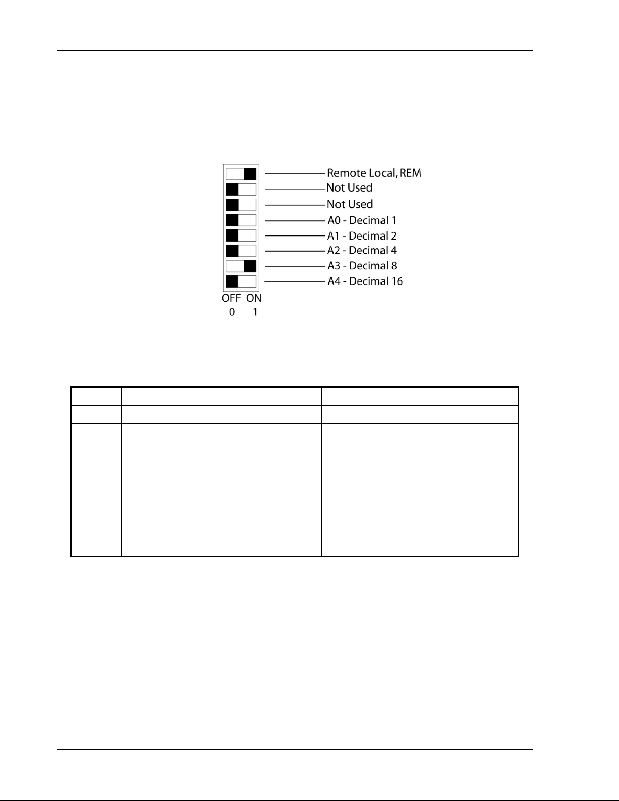
Operation with M131 Option Sorensen Ethernet Option
Switch
ON
OFF
S1-4–8
Set channel number for unit in binary:
Binary 16 OFF
Figure 5-2 shows an example of switch settings f or the DLM600 with the M6 option
and the DCS 1k and 1.2k power supplies with the M131 option, configured as an
auxiliary at channel 8, in remote mode.
Note: Only the Remote/Local switch is used f or Et her net .
Figure 5-2. Switch Configuration for M6 or M131 set to Channel 8
Table 5-1 Definitions of S1 Switch Settings
S1-1 Remote control Local control
S1-2 Not used. Not used.
S1-3 Not applicable. Must be OFF. Unit operates as an auxiliary unit.
(Channels 0 and 1 see note below.)
S1-4
S1-5
S1-6
S1-7
S1-8
Binary 1 ON
Binary 2 ON
Binary 4 ON
Binary 8 ON
Binary 16 ON
Binary 1 OFF
Binary 2 OFF
Binary 4 OFF
Binary 8 OFF
Note: Channel numbers 0 and 1 are invalid for any aux iliary device, becaus e t he M130
implementation of the SCPI language reserves channel 0 for t he “global” address to
address all channels, and it reserves channel number 1 as the default num ber for the
master channel.
5-2 M130/M131 Programming Manual
Page 95

Sorensen Ethernet Option SCPI Status Implementation
5.3 SYSTEM INSTALLATION
Follow the steps below, illustrated in Figure 5-3, to install the conf ig ured M131 into
your system:
1. Configure the M131 as described in the Configuration sect ion above.
2. Connect the master unit’s RS-485 output connector, J2, to the auxiliary unit’s
RS-485 input connector, J1, using the m odular cable.
3. If there are additional auxiliary units, connect the installed auxiliary unit’s RS-485
output connector, J2, to t he additional auxiliary unit’s RS-485 input connector,
J1, using the modular cable.
4. Connect the 120 ohm resistive termination assembly to the last auxiliary unit’s J2
connector.
5. Connect power to the system, power it up, and verify that the green REMOTE
LED on the front panel is ON.
6. Test the link by communicating with the auxiliary unit from the mas t er unit , using
the *IDN[n]? command. Note that [n] is t he channel num ber—for example,
*IDN2? calls channel 2. (In response t o t his s t r ing, t he s ys t em r eturns the power
supply model number and the firmware ver sion. )
NOTE: T he slave baud rat e is 9600.
Figure 5-3. RS-485 System Interconnect i on w ith Two Auxiliaries
M130/M131 Programming Manual 5-3
Page 96

Operation with M131 Option Sorensen Ethernet Option
5.4 RS-485 INTERFACE
The RS-485 interface is accessible throug h the two rear-panel, 6-pin, RJ-11
connectors, J1 and J2, depicted in Figure 5-4.
Figure 5-4. M131 Rear Panel RS-485 Connectors Pinout
5.5 PROGRAMMING THE M131 UNIT (EXAMPLE)
The following example programs the M131 unit to:
• Turn on
• Initialize to 2 VDC, at 1A
• Set overvoltage protection level at 3 VDC
• Verify proper power-on initialization
• Save and store changes.
// Use SYST:ERR? after each comm and t o verify no programming errors.
// turn on the unit.
*CLS // clear the unit to its power on default set tings.
*RST // reset the unit.
CAL[n]:INIT:CURR 1.0 // set power-on initial current to 1. 0A.
CAL[n]:INIT:CURR? // confirm power-on initial current set ting.
CAL[n]:INIT:VOLT 2.0 // set power-on initial voltage to 2. 0V.
CAL[n]:INIT:VOLT? // confirm power-on initial voltage setting .
CAL[n]:INIT:VOLT:PROT 3.0 // set power-on initial overvoltage protection to 3.0V.
CAL[n]:INIT:VOLT:PROT? // confirm power-on initial overvoltage protect ion setting.
CAL[n]:UNLOCK “6867” // unlock nonvolatile memory for calibration value storage.
CAL[n]:STORE // st ore the calibration values in nonvolatile memory.
CAL[n]:LOCK // lock nonvolatile memory for calibration value protect ion.
// cycle power to unit.
// note voltage is initialized to 2.0 VDC via front panel.
SOUR[n]:CURR? // confirm power-on initial current set ting.
SOUR[n]:VOLT? // confirm power-on initial voltage setting .
SOUR[n]:VOLT:PROT? // confirm power-on initial overvoltage protect ion set ting.
5-4 M130/M131 Programming Manual
Page 97

INDEX
A
Accuracy
programming, 4
readback, 4
C
CALibrate[n], 3-12
Calibration, 4-1
Current Measurement/Readback
Calibration, 4-9
Current Programming, 4-7
Current Programming Calibrat ion, 4-7
Overvoltage Protection Programming
Calibration, 4-6
Setup for Calibration, 4-2
Voltage Measurement/Readback
Calibration, 4-5
Voltage Programming, 4-3
Voltage Programming Calibration, 4-3
Warning , 4-1, 4-2
Calibration Dates,
Non-Volatile Update, 4-10
Calibration SCPI Command
Reference, 3-13
Summary, 3-12
Calibration SCPI Command Subsystem, 3-
12
Communication Methods, 2-13
Configuration
Ethernet/Lan, 3
Conventions, 3-9
[ ], 3-9
E
Error/Event Queue, 3-4
SCPI Error Codes, 3-4
Examples of Using SCPI Commands, 3-34
External User Control Signal Connector
FAULT output signal, 2-10
FOLDBACK output signal, 2-10
ISOLATION output signal, 2-10
POLARITY output signal, 2-10
SENSE output signal, 2-10
SHUTDOWN TTL input signal, 2-10
SYNC output signal, 2-10
External User Control Signal Connector, 2-
10
Illustration of Open Collector, TTL Input,
and Relay Output Circuits, 2-13
Warning , 2-13
F
Features, 1
Function
Ramp, 3-24
Functions
Programmable, 2
Readback, 2
I
IEEE-488.2 and SCPI Conformance
Information, 3-8
IEEE-488.2 Common Command
Subsystem, 3-10
*CLS, 3-10
*ESE, 3-10
*ESR?, 3-10
*IDN?, 3-10
M130/M131 Programming Manual Index-1
Page 98

Operation with M131 Option Sorensen Ethernet Option
*OPC, 3-10
*RST, 3-10
*SRE, 3-10
*STB?, 3-11
*TST?, 3-11
*WAI, 3-11
IEEE-488.2 Register Definitions, 3-1
L
Local Operation, 2-9
M
Measure SCPI Command
Reference, 3-16
Summary, 3-16
Measure SCPI Command Subsystem, 3-16
MEASure[n], 3-16
Multiple Source Control with the M131
Option, 2-32
RS-485 Rear Panel RJ-11 Connector
Pinout, 2-32
O
Operation Status and Questionable Status
Registers, 3 -4
Operation, M131, 5-1
Output SCPI Command
Reference, 3-18
Summary, 3-18
Output SCPI Command Subsystem, 3-18
OUTPut[n], 3-18
P
Parameter Definitions, 3-8
0+NR1, 3-8
0+NRf, 3-8
boolean, 3-8
NR1, 3-8
NRf, 3-8
string, 3-8
Power-On Conditions, 2-9
Default, 2-9
Programming
accuracy, 4
resolution, 4
Protection Event Status Registe r, 3-3
Q
Queries, 3-9
R
Ramp Function, 3-24
Ramping
Description, 3-24
Raw Socket Interface, 2-13
Readback
accuracy, 4
resolution, 4
Rear Panel Configuration Switch
Remote/Local Selection, 2-9
Rear Panel Configuration Switch S1, 2-8
Register Definitions
IEEE-488.2, 3-1
Remote Operation, 2-9
Remote Programming via RS-232, 2-31
Resolution
programming, 4
readback, 4
RS-485 Interface, 5-4
S
SCPI
Conformance Inform ation, 3-8
Error Codes, 3-4
Operation Status, 3-4
Parameter Definitions, 3-8
Protection Condition/Event Status
Registers, 3 -3
Questionable Status Registers, 3-4
Standard Event Status Register (ESR), 3-
2
Status Byte, 3-1
SCPI Command Operation, 3-1
CALibrate[n], 3-12
MEASure[n], 3-16
OUTPut[n], 3-18
Warning, 3-19
SOURce[n], 3-19
STATus[n], 3-25
TRIGgered[n] , 3-32
SCPI Commands
examples of using, 3-34
Serial Poll Operation, 3-6
Setup Procedure, 2-1
Source SCPI Command
Reference, 3-21
Summary, 3-19
Index-2 M130/M131 Programming Manual
Page 99

Sorensen Ethernet Option Index
Source SCPI Command Subsystem, 3-19
SOURce[n], 3-19
Specifications, 3
Standard Event Status Register (ESR), 3 -2
Status Byte, 3-1
Status Flags Register, 3-24
Status SCPI Command
Reference, 3-25
Summary, 3-25
Status SCPI Command Subsystem, 3-25
STATus[n], 3-25
Switch Settings, M131, 5-2
Synchronization Pulse, 2-10
System Installation, M131, 5-3
System SCPI Command
Reference, 3-29
Summary, 3-28
System SCPI Command Subsystem, 3-28
T
Trigger SCPI Command
Reference, 3-32
Summary, 3-32
Trigger SCPI Command Subsystem, 3-32
TRIGgered[n], 3-32
U
Units, 3-9
W
Web Server, 2-13
Configuration page, 2-17
Home page, 2-15
Login window, 2-15
Security page, 2-24
Settings page, 2-20
Slave Info page, 2-29
Status page, 2-22
Troubleshooting, 2-29
M130/M131 Programming Manual Index-3
 Loading...