

Page 1
Technical Note
ReFlex Power™ Mating Connectors for LPDC-16V Module
Document No. W380270-01 Rev E • 1/23/2009
PURPOSE
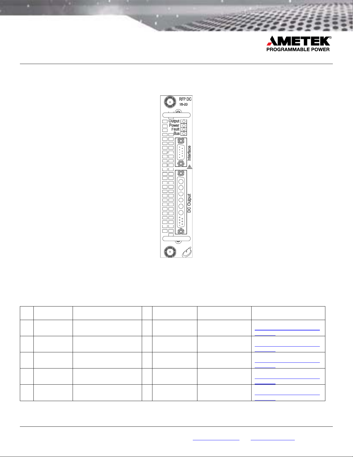
Provide mating connector information for the ReFlex Po wer™ Low Powe r DC, 16V (LPDC-16V) module.
Figure 1. LPDC-16 Front View
MATING CONNECTOR KIT
LPDC-16V Mating Connector Kit - AMETEK Part No. 5380270-01, mates with RFP-D1016-021-XXXX, and includes the following
for both Interface and DC output connectors:
Bill of Material
Item
AMETEK
Part No.
1 856-214-07
2 856-745-51
3 856-247-39 Conn, Backshell, 37P, Strt, 2 PC 1 D37000Z00 Positronic Industries
4 856-214-09
5 856-247-10 Conn, Backshell, 9P, DSUB, 2 PC 1 D9000Z00 Positronic Industries
Conn, 13P, DSUB, 8/20AWG,
Male
Contact, 10AWG, 30A, CL ETRY,
Male
Conn, 9P, DSUB, 20-24AWG,
Crimp, Male
Description Qty
Manufacturer
Part No.
1 CBD13W6M2000Z Positronic Industries
4 MC4010D Positronic Industries
1 SD9M1000Z Positronic Industries
Manufacturer Suggested Source(s)
Positronic Ind.
http://www.connectpositronic.com/
default.cfm
Positronic Ind.
http://www.connectpositronic.com/
default.cfm
Positronic Ind.
http://www.connectpositronic.com/
default.cfm
Positronic Ind.
http://www.connectpositronic.com/
default.cfm
Positronic Ind.
http://www.connectpositronic.com/
default.cfm
9250 Brown Deer Road, Sa n Diego CA 92121 • Tel: 858-4 50-008 5 • Fax: 858-458- 0267 • e mail: sal es@progra mmablep ower.com • Web: www.programm ablepow er.com
©2008 AMETEK Programmable Pow er, Inc. • All rights reserv ed. • AME TEK is a tr ademark o f AMETEK, Inc .
1 of 4
Page 2
Technical Note
ReFlex Power™ Mating Connectors for LPDC-16V Module
Document No. W380270-01 Rev E • 1/23/2009
RECOMMENDED TOOLS (NOT INCLUDED WITH MATING CONNECTOR KIT)
Hand crimp: Positronic Industries P/N 95 07-0-0-0
Pneumatic crimp: Positronic Industries P/N 9550-1-0
Insertion/extraction tool: Positronic Industries P/N M81969/1-02
Pins A1 through A6 insertion/extraction: Positronic Industries P/N 4311-0-0 -0
INTERFACE CONNECTOR
External isolated digital and analog cont rol interface.
Connector: Positronic Industries P/N SD9M1000Z, AMETEK P/N 856-214-09
Crimp contacts: Positronic Industries P/N MC75 20D (initially suppli ed with conne ctor)
Backshell: Positronic Industries P/N D9000Z00, AMETEK P/N 856-247-10
Wire size: Maximum gauge 20 AWG (recommended)
Maximum length 10 meters (can be extended subject to enviro nment, cable type, and interfa ce circuits).
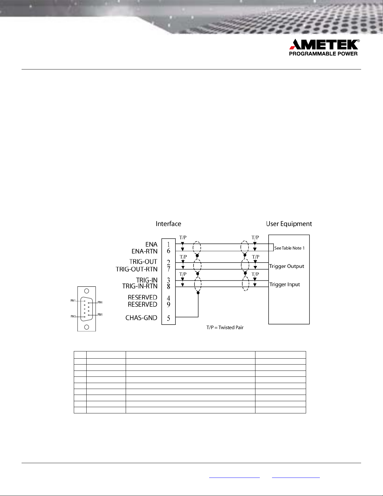
INTERFACE PINOUT
Figure 2. Interface Connector, Front Panel View, and Interface Connector Wiring Diagram
Pin
1 ENA1 Input: module output enable TTL logic level
6 ENA-RTN1 Input: return for ENA signal; connected to Pin-7/8 Signal common
2 TRIG-OUT Output: trigger output signal TTL logic level
7 TRIG-OUT-RTN Output: return for TRIG-OUT; connected to Pin-6/8 Signal common
3 TRIG-IN Input: trigger input signal TTL logic level
8 TRIG-IN-RTN Input: return for TRIG-IN; connected to Pin-6/7 Signal common
4 RESERVED
9 RESERVED
5 CHAS-GND Shield ground Chassis ground
1
Enable signal is internally pulled up to +5 V with a 10 K resistor. To enable the module, the signal is pulled low (<= 0.5 V) with respect to
the ENA RTN signal; this may also be accomplished by shorting Pin 1 to Pin 6.
9250 Brown Deer Road, Sa n Diego CA 92121 • Tel: 858-4 50-008 5 • Fax: 858-458- 0267 • e mail: sal es@progra mmablep ower.com • Web: www.programm ablepow er.com
Name Function Signal Level
©2008 AMETEK Programmable Pow er, Inc. • All rights reserv ed. • AME TEK is a tr ademark o f AMETEK, Inc .
2 of 4
Page 3
Technical Note
ReFlex Power™ Mating Connectors for LPDC-16V Module
Document No. W380270-01 Rev E • 1/23/2009
OPTIONAL INTERFACE CONNECTOR ACCESSORIES
• AMETEK P/N 5380508-01, 9-pin Loop-back Connector Assembly. Includes a jumper wire between Pins 1 and 6 to enable
the module outputs.
• AMETEK P/N 5380443-01, Power Module 9ft. Unterminated Interface Cable Assembly. Use when interfacing to an external
system.
• AMETEK P/N 5380443-03, Power Module, Right Angle, 9ft. Unterminated Interface Cable Assembly. Use when interfacing
to an external system.
DC OUTPUT CONNECTOR
Connector: Positronic Industries P/N CBD13W6M2000Z, AMETEK P/N 856-214-07
Pin: Positronic Industries P/N MC4010D, AMETEK P/N 856-745-51
Backshell: Positronic Industries P/N D37000Z00, AMETEK P/N 856-247-39
Wire size: Refer to table for recommen ded wire g auge/length
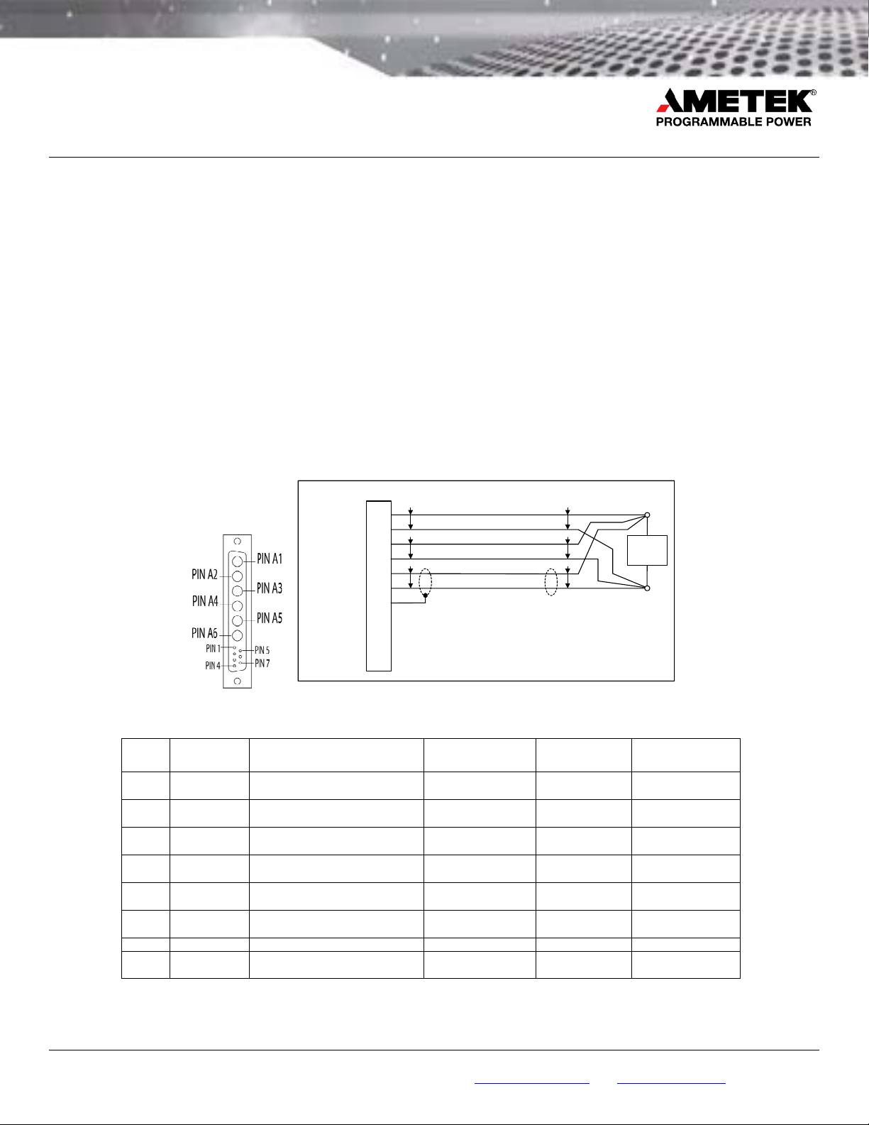
DC OUTPUT PINOUT
DC Output
Out
Out_Rtn
Out
Out_Rtn
Sense
Sense_Rtn
Chas Gnd
N/U
N/U
N/U
N/U
A1
A2
A3
A4
2-3
6-7
A5
A6
T/P
T/P
T/P
1
5
4
T/P = Twisted Pair; N/U = Not Used
T/P
T/P
Load
T/P
Figure 3. DC Output Connector, Front Panel View, and DC Output Connector Wiring Diagram
Pin Name Function Signal Level
A1 OUT
A2 OUT-RTN
A3 OUT
A4 OUT-RTN
1 SNS
5 SNS-RTN
4 CHAS-GND Shield ground Chassis ground 20 100
A5, A6,
2,3,6,7
- Reserved - - -
Output: module output source;
connected to A3
Output: return for output source,
OUT; connected to A4
Output: module output source;
connected to A1
Output: return for output source,
OUT; connected to A2
Input: remote sense connection for
OUT
Input: remote sense connection for
OUT-RTN
±16V; ±200V,
maximum to chassis
±16V; ±200V,
maximum to chassis
±16V; ±200V,
maximum to chassis
±16V; ±200V,
maximum to chassis
±16V; ±200V,
maximum to chassis
±16V; ±200V,
maximum to chassis
Max. Wire
Gauge, AWG
10
10
10
10
20 100
20 100
Max. Wire
Length, ft
100, for 1.5V line
drop at 10.3A
100, for 1.5V line
drop at 10.3A
100, for 1.5V line
drop at 10.3A
100, for 1.5V line
drop at 10.3A
9250 Brown Deer Road, Sa n Diego CA 92121 • Tel: 858-4 50-008 5 • Fax: 858-458- 0267 • e mail: sal es@progra mmablep ower.com • Web: www.programm ablepow er.com
©2008 AMETEK Programmable Pow er, Inc. • All rights reserv ed. • AME TEK is a tr ademark o f AMETEK, Inc .
3 of 4
Page 4

Technical Note
ReFlex Power™ Mating Connectors for LPDC-16V Module
Document No. W380270-01 Rev E • 1/23/2009
DC OUTPUT CONNECTOR ACCESSORIES
• AMETEK P/N 5380444-01, LPDC 16V Module, 9ft. Unterminated DC Output Cable Assembly.
• AMETEK P/N 5380444-03, LPDC 16V Module, Right Angle, 9ft. Unterminated DC Output Cable Assembly.
9250 Brown Deer Road, Sa n Diego CA 92121 • Tel: 858-4 50-008 5 • Fax: 858-458- 0267 • e mail: sal es@progra mmablep ower.com • Web: www.programm ablepow er.com
©2008 AMETEK Programmable Pow er, Inc. • All rights reserv ed. • AME TEK is a tr ademark o f AMETEK, Inc .
4 of 4
 Loading...