

Page 1
p r e s s u r e
Specification Sheet
SS-CP-2179-US
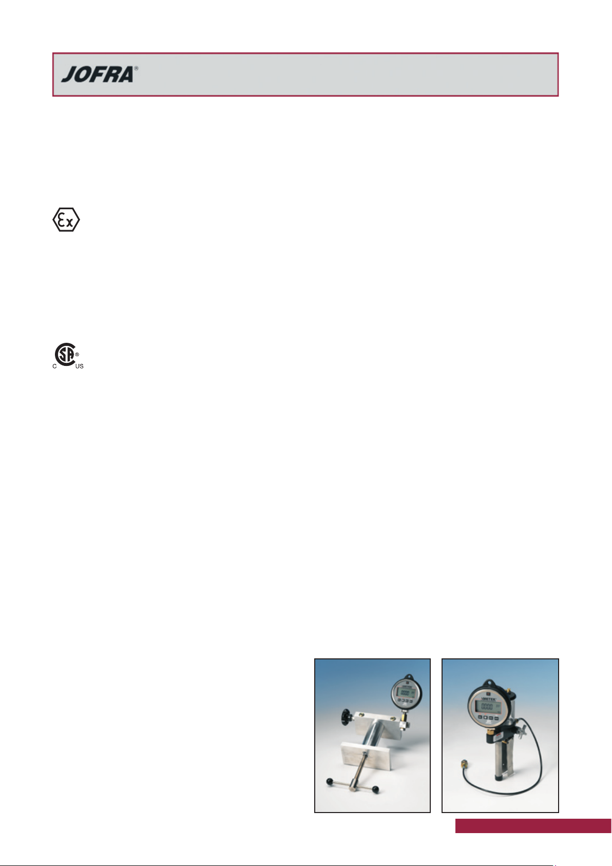
NEW SYSTEM A + B PUMPS
Certified for use in potentially
explosive environments
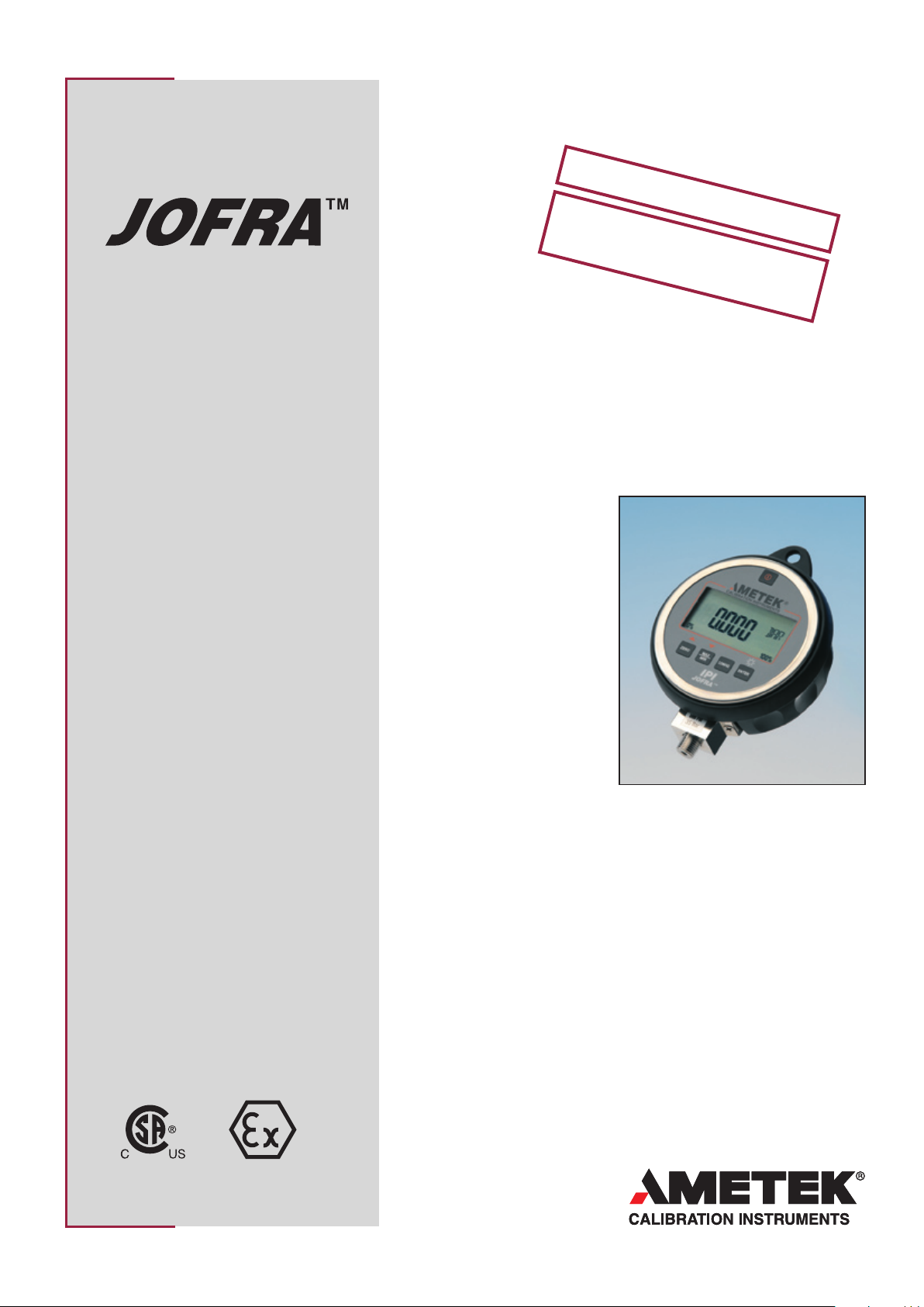
Model IPI
Industrial Pressure Calibrator
Pressure range
IPI030C Vacuum to 2 bar / 30 psi
IPI100C Vacuum to 7 bar / 100 psi
IPI300C Vacuum to 21 bar / 300 psi
IPI500C Vacuum to 35 bar / 500 psi
IPI015G 0 to 1 bar / 15 psi
IPI01KG 0 to 70 bar / 1,000 psi
IPI02KG 0 to 140 bar / 2,000 psi
IPI03KG 0 to 200 bar / 3,000 psi
IPI05KG 0 to 350 bar / 5,000 psi
IPI10KG 0 to 700 bar / 10,000 psi
High accuracy
±0.05% of F.S. for positive pressure
Vacuum ranges to 500 psi (35 bar)
High flexibility
Easily disassemble the test system and
use the indicator for other tasks
True field indicator
Lightweight and portable with full temperature-compensation, long battery life and
large display for easy visibility
Record min and max readings
Capture the min and max pressure
readings for safety valve applications
Complete marine program
Part of a complete program of marine
approved temperature, pressure and signal
calibrators; including temperature sensors
See more at www.jofra.com
ATEX and CSA certification
The IPI Indicator is ATEX and CSA
certified and designed for use in
potentially explosive environments
PRODUCT DESCRIPTION
JOFRA IPI indicators bring
together the ease of an analog
gauge with the accuracy and
easy-to-read display of a digital calibrator.
Use the JOFRA IPI in applications from safety valve checks
to system pressure verification.
Furthermore the IPI indicator
is ATEX and CSA certified for
use in potentially explosive
environments such as oil refineries, chemical plants and offshore platform, where there is
a risk of inflammable gases.
Features
This series is designed to meet your pressure measurement applications
and make the tasks easier. The IPI offers 18 different pressure units,
long battery life, high accuracy, and even serial communications. The
accuracy of the IPI rivals that of a pressure calibrator and is temperature
compensated for shop or in process applications. This versatile unit is
available as a stand alone indicator or in a complete test system.
You can perform a calibration locally without returning the IPI unit to the
manufacturer. All you need is an accurate pressure reference. If you do
require factory calibration, the pump and indicator are independent and
only the indicator needs to be returned.
The JOFRA IPI is available as an indicator or in one of 6 test ready systems that are complete and equipped to meet your pressure measuring
or testing needs.
CSA
ISO 9001 Manufacturer
ATEX
Page 2
Model IPI
Industrial Pressure Calibrator
Specification Sheet
SS-CP-2179-US
The JOFRA IPI digital pressure indicator takes the concept
of an analog test gauge, and brings it to a new level. The
IPI combines the accuracy of digital technology with the
simplicity of an analog gauge, and achieves performance,
ease-of-use, and a feature set unmatched in the pressure
measurement world. Setup of the IPI is fast and straightforward, through a menu-driven display, with minimal text,
and intuitive functions, that is simple enough to allow the
indicator to be used anywhere in the world, without the
need for multilingual displays.
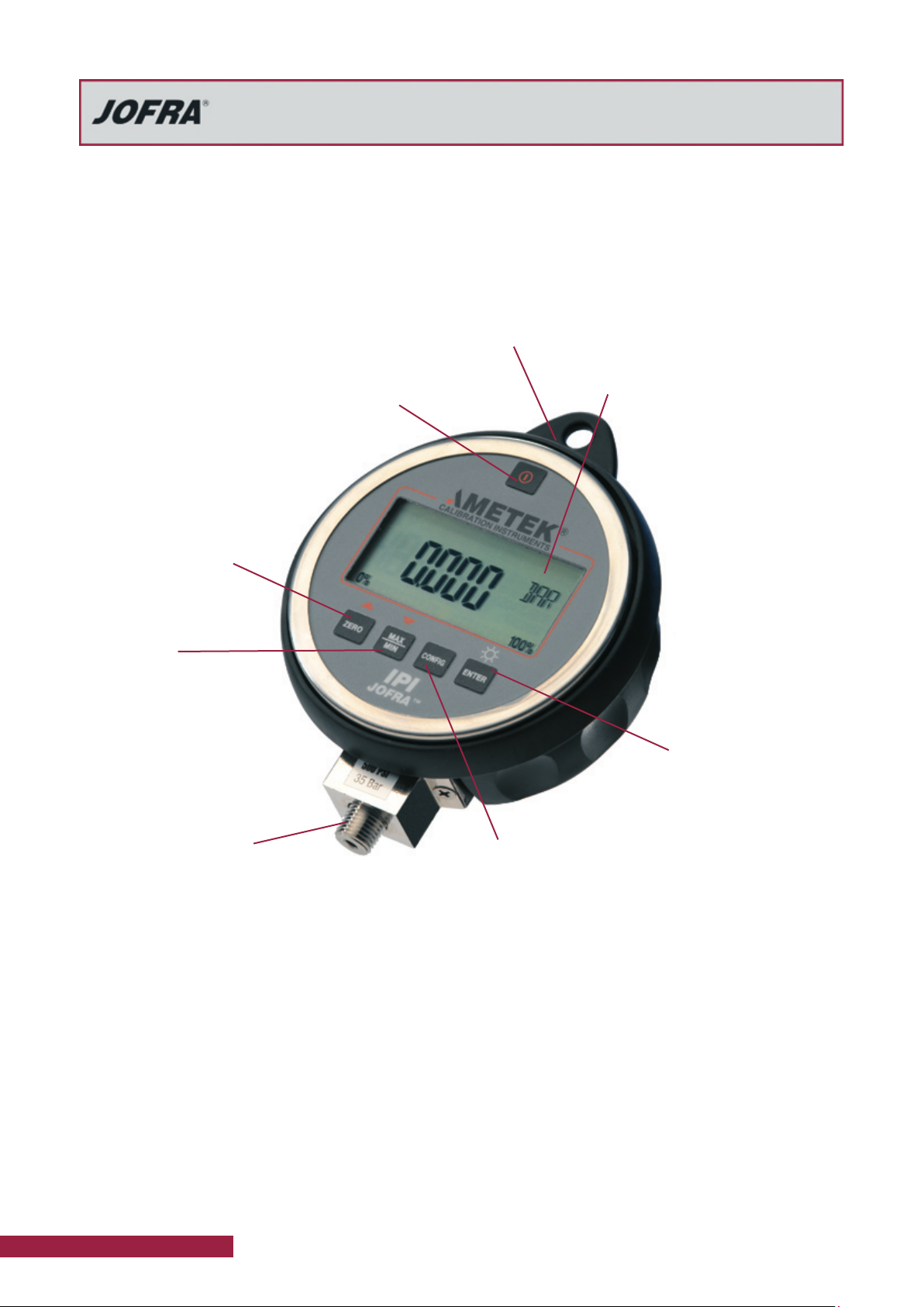
ON / OFF
The IPI is delivered with the auto-shutoff active and set
to 30 minutes: like many of our other instruments.
This feature can be reduced from 30 minutes
down to 1 minute in 1 minute increments. In
cases where a constant reading is necessary, this can also be turned completely
off to allow for continuous operation.
ZERO
Keep the high accuracy:
ZERO the instrument before
every test.
MAX / MIN
A MIN/MAX function reads
the maximum and minimum
pressure that have been automatically stored. Monitor a
safety valve or look for pressure
spikes in the process. The IPI
also have the ability to check the
minimum and maximum readings
during the ransient.
Protective boot
Standard configuration IPI units and
those supplied with systems are
delivered with a protective boot.
Units with back mounting and the
24 VDC power supply are not delivered with the protective boot due
to design limitations.
Clear dual line display
The IPI display does more than
just show a pressure reading. The
user can check temperature and
exact battery voltage through
the use of the keypad. The
large, 5 1/2 digit, 0.65 in
(1.65 cm) character display
is large and easy-to-read;
even from a distance.
Icons are also included
to indicate battery life,
engineering units, and
there is a bar graph that
shows the percentage of
scale reading. All of this
information can be read
in low light with the use of
the backlight.
ENTER
Save selections and turn
the backlight on and off.
Pressure connections
1/4” NPT male lower connection is standard. A 1/4” BSP male
adapter is included. The IPI may be
ordered with a back mounting configuration.
This design has the 1/4 in. NPT male connection on the back of the case vice the lower manifold
connection. This allows for use in panel mounted applications or in applications where flat mounting is necessary
such as in an overhead. This configuration is not delivered
with a protective boot.
External power
Sometimes it is more convenient to take advantage of an
existing power source rather than using batteries. The IPI
may be ordered with a 24 VDC power supply option. The unit
has terminals to accept the positive and negative leads to
allow for easy connection to the power supply. These units
will not be supplied with batteries and batteries should not
be installed when the unit is connected to 24 VDC power.
2 www.jofra.com
CONFIG
This is the key to access all user-settable functions. The
CONFIG key is used in conjunction with the ▼ and ▲
functions on the ZERO and MAX/MIN keys to select and
change different functions.
You can set one of 20 engineering units, change the autoshutoff function setting, display the actual battery voltage,
display the actual temperature (in °C or °F), turn the dampening on or off, change the sample rate, and set the Tare
value. In addition to the 20 available engineering units on the
IPI, you can create your own unit to meet your measurement
need. For example, if you need to take a level measurement,
simply determine the pressure that equates to one unit of
that measurement and set that as your engineering unit. The
application may require gallons, feet, inches, meters, liters, or
similar; with the IPI you can take the measurement.
Serial communications
The IPI has a serial port that is accessible though the back
of the case. This feature uses standard ASCII commands to
allow for extraction of data from the IPI while taking readings.
This requires the optional serial cable.
Page 3
Model IPI
Industrial Pressure Calibrator
Specification Sheet
SS-CP-2179-US
Hazard location information / approvals
An explosive atmosphere is defined as a ”mixture with air,
under atmospheric conditions, of flammable substances in
the form of gases, vapours, mists or dusts in which, after
ignition has occurred, combustion spreads to the entire
unburned mixture”.
The standard in the European Union has been set
with the 9/94/EC Directive, commonly called ATEX
(“Atmosphères Explosibles,” French for explosive
atmospheres).
The JOFRA IPI Industrial Pressure Indicator is ATEX
approved by KEMA as complying with the Essential Health
and Safety Requirements related to the design and construction of equipment and protective systems intended
for use in potentially explosive atmospheres given in
Annex II in the directive, and with the following rating: II 3
G EEx nA IIB T6 (Ta=–10°C... +55°C).
The JOFRA IPI Industrial Pressure Indicator is
also certified by CSA as conforming to relevant
Canadian and USA standards with the following
rating: Class 1, Div. 2, Groups A-D.
See the definitions regarding hazardous locations in NFPA
70, Article 500 or CSA C22.1 Section 18. NFPA 70, Article
500 and CSA C22.1 Section 18.
Field recalibration
The IPI does not need to be returned to the factory for
calibration. If you have a reliable and accurate pressure
reference or a local laboratory, you may re-calibrate the
IPI locally. This feature is password protected.
Sampling rate
The IPI sampling rate is user selectable. If you want to
capture fast system transients, the IPI can take a reading
10 times per second. Conversely, you may want to conserve battery life and only need periodic samples. Then,
you can select 1 sample per every 2 seconds. This works
well for in process and panel mounted applications. You
can also choose the accepted instrument sampling rate of
3 samples per second for normal use or to allow for filtering, you can select 1 sample per second.
Damping adjustment
The damping function can be turned on or off on the IPI.
This allows for readings to be integrated, which accounts for
momentary changes such as those from pulsing sources.
JOFRACAL CALIBRATION SOFTWARE
JOFRACAL calibration software ensures easy calibration
of RTD´s, thermocouples, transmitters, thermoswithes,
pressure gauges and pressure switches. JOFRACAL can
be used with JOFRA DPC-500, APC, CPC and IPI pressure calibrators, all JOFRA temperature calibrators, as well
as JOFRA AMC910, ASC300 multi signal calibrator and
ASM-800 signal multi scanner. When used with JOFRA
ASM-800 signal multi scanner, JOFRACAL can perform a
simultaneous semi automatic calibration on up to 24 pressure and/or temperature devices under test in any combination.
JOFRACAL software controls the complete calibration
procedure, stores the results and provides a calibration
audit trail through hard-copy certificates. All calibration
data are stored for each sensor to monitor drift and optimise recalibration intervals. A scheduler feature allows
planning of future calibrations.
Please find more information about JOFRACAL calibration
software in specification sheet SS-CP-2510, which may be
found at www.jofra.com
REQUIREMENTS JOFRACAL
Minimum hardware requirements:
Intel® Pentium® lI 1.4 GHz processor.
•
•
64MB RAM (128MB recommended)
•
80MB free disk space on hard disk (120MB
recommended) prior to installation
•
Standard VGA (800x600, 256 colours). 1024x768
recommended.
CD-ROM drive for installation of program
•
•
1 or 2 free RS-232 serial ports, depending on
configuration
Minimum software equirements:
Microsoft Windows® 98,Microsoft Windows® NT 4.0,
•
Microsoft Windows® 2000, Microsoft Windows® ME,
Microsoft Windows® XP, Vista.
System fonts: MS Sans Serif and Arial
•
Tare
Beyond zeroing the IPI, you may have to account for
residual pressure. The Tare feature allows you to take care
of that error and prevent the manual calculation of the difference. This can be used in combination with the custom
engineering units to make the level measurements easier.
Temperature display and compensation
Because the IPI is designed for in-process tasks, temperature
compensation is included to make the job easier. This allows
the IPI to maintain accuracy over the measurement range. The
measured temperature may be checked from the keypad.
www.jofra.com 3
Page 4
Model IPI
IPI
111 mm
36 mm
38 mm
25,4 mm
99,3 mm
125 mm
Industrial Pressure Calibrator
Specification Sheet
SS-CP-2179-US
FUNCTIONAL SPECIFICATIONS
Pressure range
psi ...........................................vacuum to 30, 100, 300, 500
bar ....................................................vacuum to 2, 7, 21, 35
psi .................... 0 to 15, 1,000, 2,000, 3,000, 5,000, 10,000
bar ........................................ 0 to 1, 70, 140, 200, 350, 700
Engineering units
User defined ................................... One user-definable unit
User selectable ........................................................ 20 units
(PSI, Bar, kg/cm2, inH2O (4 °C, 20 °C or 60 °F), ftH2O (4 °C, 20
°C or 60 °F), mmH2O (4 °C and 20 °C), cmH2O (4 °C and 20 °C),
mH2O (4 °C and 20 °C), KPa, mBAR, inHg, mmHg, Torr)
Not all units are availibale in all ranges.
Pressure accuracy
Pressure ...........................................................±0.05% F.S.
Full temperature compensation ......0 to 50°C / 32 to 122°F
Vacuum (30, 100, 300, 500 psi indicator) ........ ±0.25% F.S.
Vacuum (2, 7, 21, 35 bar indicator) ..................±0.25% F.S.
Including non-linearity, hysteresis, repeatability, and temperature
effect.
F.S. (full scale) = maximum gauge pressure in psi
Serial communication interface
Connector .......................................................... Stereo jack
Serial ......... 0-3 VDC, 9600 baud, 8 data, no parity, 1 stop
Protocol ..................................... ASCll command language
Media compatibility
Liquids and gasses compatible with 316 stainless steel.
Environmetal
Storage temperature ....................-20 to 70°C / -4 to 158°F
Operating temperature ...............-10 to 55°C / -14 to 131°F
Pressure connection
All ranges .....................................................1/4” NPT male
Adapters to 1/4” BSP male are included as standard
Pressure overload
1 to 35 bar / 15 to 500 psi…….. ............................3X range
70 to 350 bar / 1,000 to 5,000 psi ........................2X range
700 bar / 10,000 psi …………… .........................1.5X range
Overload alarm ………………………………… OL on display
Overload alarm range ……………………… …… 1.2X range
Display
Display .......................................................... Backlight, blue
Display resolution .......................... 5 digit floating decimal
Bar graph........................................ 20 segment, 0 to 100%
Display indicators ..............................Engineering units icon
...................................................Low battery indication icon
.............................. Battery life indication utilizing bar graph
............................................. Measured temperature display
Display update ......................................... twice per second
Power supply
Battery .......................................................... (3) AA Alkaline
Battery life ......... 1500 operational hours without backlight
Battery life ......... 2000 operational hours without backlight
..............................................................at low sampling rate
Battery life .................150 operational hours with backlight
Low battery indicator .............................................at 3 VDC
Optional input port .....................24 VDC connection
1) Units delivered with 24 VDC power supply connection are not
supplied with batteries
2) Batteries should not be installed when using 24 VDC power
supply as damage to the IPI may occur
3) Units with 24 VDC power supply connection cannot be ordered
with the protective boot option
1) 2) 3)
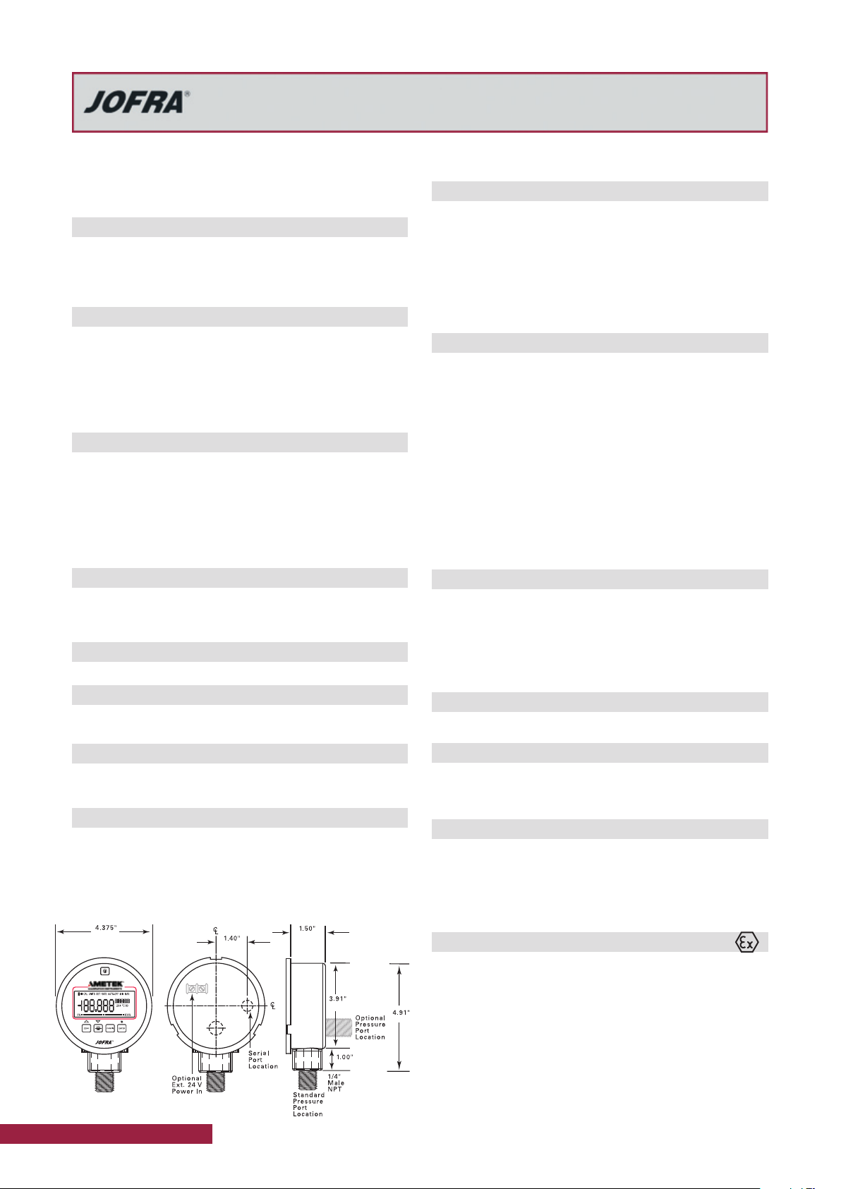
Instrument dimensions
Indicator LxWxH ..... 125 x 111 x 38 mm / 4.9 x 4.4 x 1.5 in
Indicator weight (including battery) ................1.6 lb / 0.7 kg
Input port ..........................1/4” NPT Male lower connection
Optional input port ........1/4” NPT Male back connection 1)
3) Units with back connection cannot be ordered with the protective boot option
Shipping dimensions
Indicator LxWxH ... 250 x 160 x 100 mm / 9.8 x 6.3 x 3.9 in
Indicator weight ..............................................1.8 lb / 0.8 kg
Instrument case
Rating ..........................................................NEMA 4/IP65
1) Does not apply if the serial connection is in use or if the
external 24 VDC power option is used.
1)
Approvals - IPI system
CE Conformity .............. EN61326: 1998, EN60079-0: 2006,
................................................................. EN60079-15:2005
The JOFRA IPI systems are type approved by Det Norske
Veritas. Find the certificate at www.jofra.com
Approval, Certificate no. .........................................A-10549
Ex approvals - IPI indicator only
CSA ......................................Class 1, Div. 2, Groups A-D
ATEX ................ II 3 G EEx nA IIB T6 (Ta=–10°C... +55°C)
1)
The 24 volt version is not CSA or ATEX approved
1)
1)
4 www.jofra.com
Page 5

Model IPI
Industrial Pressure Calibrator
Specification Sheet
SS-CP-2179-US
JOFRA IPI PRESSURE RANGES
This table shows the resolutions that can be obtained by the IPI indicators throughout all engineering units.
Resolution obtained
by the IPI indicator
Imperial ranges
psi -12.000 30.000 -12.000 100.00 -12.000 300.00 -12.00 500.00
inH2O@4°C -332.17 830.42 -332.2 2768.1 -332.2 8304.2 -332
inH2O@20°C -332.76
inH2O@60°F -332.50 831.24 -332.5 2770.8 -332.5 8312.4 -332
ftH2O@4°C -27.681 69.202 -27.68 230.67 -27.68 692.02 -27.7
ftH2O@20°C -27.730 69.324 -27.73 231.08 -27.73 693.24 -27.7
ftH2O@60°C -27.708 69.270 -27.71 230.90 -27.71 692.70 -27.7
inHg@0°C -24.432 61.081 -24.43 203.60 -24.43 610.81 -24.4 1018.0
Torr -620.6 1551.5 -620.6 5171.5 -620 15514 -621 25858
Metric ranges
bar -0.8300 2.0000 -0.8300 7.0000 -0.8300 21.000 -0.8300 35.000
mbar -830.0 2000.0 -830.0 7000.0 -830.00 21000 -830 35000
kPa -83.00 200.00 -83.00 700.00 -83.0 2100.0 -83.0 3500.0
kg/cm2
cmH2O@4°C
cmH2O@20°C
mH2O@4°C
mH2O@20°C
mmHg@0°C -622.6 1500.1 -622.6 5250.4 -622 15751 -623 26252
IPI30C
Vacuum to 30 psi
Vacuum to 2 bar
831.89 -332.7 2773.0 -332.7 8318.9 -333 13865
-0.8464 2.0394 -0.8464 7.1380 -0.846 21.414 -0.846 35.690
-846.4 2039.5 -846.4 7138.2 -846 21415 -846 35691
-847.9 2043.1 -847.9 7150.8 -847 21452 -848 35754
-8.464 20.395 -8.464 71.382 -8.46 214.15 -8.46 356.91
-8.479 20.431 -8.479 71.508 -8.48 214.52 -8.48 357.54
IPI100C
Vacuum to 100 psi
Vacuum to 7 bar
IPI300G
Vacuum to 300 psi
Vacuum to 21 bar
IPI500G
Vacuum to 500 psi
Vacuum to 35 bar
13840
13854
1153.4
1155.4
1154.5
Resolution obtained
by the IPI indicator
Imperial ranges
psi 15.000 1000.0 2000.0 3000.0 5000.0 10000
inH2O@4°C 415.21 27681
inH2O@20°C
inH2O@60°F 415.62 27708
ftH2O@4°C
ftH2O@20°C 34.662 2310.8 4621.6 6932.4
ftH2O@60°C
inHg@0°C 30.540 2036.0 4072.1 6108.1 10180 20360
Torr 775.73 51715 N/A N/A N/A N/A
Metric ranges
bar 1.0000 70.000 140.00 200.00 350.00 700.00
mbar 1000.0 70000 N/A N/A N/A N/A
kPa 100.00 7000.0 14000 20000 35000 70000
kg/cm2
cmH2O@4°C
cmH2O@20°C 1021.5
mH2O@4°C
mH2O@20°C 10.215
mmHg@0°C 750.06 52504 N/A N/A N/A N/A
IPI015G
0 to 15 psi
0 to 1 bar
415.95 27730 55459 83189 N/A N/A
34.601 2306.7 4613.5 6920.2 11534 23067
34.635 2309.0 4618.0 6927.0 11545 23090
1.0197 71.380 142.76 203.94 356.90 713.80
1019.7 71382 N/A N/A N/A N/A
10.197 713.82 1427.6 2039.5 3569.1 7138.2
IPI01KG
0 to 1,000 psi
0 to 70 bar
71508 N/A N/A N/A N/A
715.08 1430.2 2043.1 3575.4 7150.8
IPI02KG
0 to 2,000 psi
0 to 140 bar
55361 83042 N/A N/A
55416 83124 N/A N/A
IPI03KG
0 to 3,000 psi
0 to 200 bar
IPI05KG
0 to 5,000 psi
0 to 350 bar
11554 23108
IPI10KG
0 to 10,000 psi
0 to 700 bar
www.jofra.com 5
Page 6

Model IPI
Industrial Pressure Calibrator
Specification Sheet
SS-CP-2179-US
JOFRA IPI System A
•
0 to 1 bar (15 psi)
•
Vacuum to 2 bar (30 psi )
•
Vacuum to 7 bar (100 psi)
•
Vacuum to 21 bar (300 psi)
This system includes the
JOFRA IPI calibrator together
with one of the following pneumatic hand pumps: T-960 and
T-970, depending on the chosen pressure range. System A
is an easy-to-use single hand operated calibration system.
No need for a flat surface to operate the system - just hold
it in your hand.
The System A comes in an aluminium carrying case with
cutouts for fittings, hose, and the complete assembled
calibration unit - no time is required to assemble the unit
every time you need it. The calibrator (indicator) can at any
time be used separately for other pressure test tasks.
A special quick connector between the pump and the indicator makes it possible to seperate the system in seconds
and to swivel the indicator for easy viewing.
The JOFRA IPI delivery always includes a protective boot
for the indicator. All IPI indicators used in System A are
delivered calibrated in both pressure and vacuum.
Only the IPI indicator is approved for use in potentially explosive
atmospheres.
T-960 and T-970 pumps for system A
Model T-960 pneumatic pressure pump features an
extended range vernier adjustment for precisely controlling
pump pressure and comfortable pistol grip handle.
Model T-970 pneumatic pressure pump is similar to the T960, but generate pressure up to 40 bar (580 psi).
Pressure range, T-960 ..................... 0 to 2 bar / 0 to 30 psi
Pressure range, T-970 ..................0 to 40 bar / 0 to 580 psi
Type .....................................................................Pheumatic
Test medium..................................................................... Air
Operation .................................................................. Scissor
“O”-rings ..................................................................Buna-N
Wetted parts ............................ Aluminium, brass, stainless,
...................................................... steel, nylon, Nylatron GS
Connection to test object....................... Hose 0.6 m / 24 in
........................with 1/4” BSP and NPT female terminations
Size .........................21.6 x 12.1 x 6.2 cm / 8.5 x 4.8 x2.4 in
Weight ............................................................1.4 kg / 3.0 lb
Ordering
Part No. Description
T-960 Pump: 0 to 2 bar (30 psi)
T-970 Pump: 0 to 40 bar (580 psi)
Included with System A delivery
Standard delivery (see page 12)
•
Hand pump T-960 or T-970
•
3/8” BSP female adapter with 1/4” BSP and NPT
•
female terminations
0.6 m / 24 in hose with 1/4” BSP and NPT female
•
terminations
Quick connector between pump and indicator
•
1 roll of Teflon tape
•
Protective carrying case
•
Accessories
Part No. Description
75P014 Service kit for T-960 pump
75P016 Service kit for T-970 pump
T-733-2 Pressure hose for T-960/970, 0.6 meter std.
T-733-3 Pressure hose for T-960/970, 0.5 meter
T-733-4 Pressure hose for T-960/970, 1.0 meter
T-733-5 Pressure hose for T-960/970, 2.0 meter
T-733-6 Pressure hose for T-960/970, 5.0 meter
65R191 Set of BSP female fittings, teflon tape, packings
* Fitting size : 1x1/8”, 1x3/8”, 1x1/2”
65R192 Set of NPT female fittings, teflon tape, packings
* Fitting size : 1x1/8”, 1x1/4”, 1x3/8” 1x1/2”
60R191 1 set of packing and seals for 65R191 and 65R192
123958 RS232 cable with stereo Jack connector, 2m/6ft
124716 4x 1,5 Volt rechargeable batteries
124718 Charger for rechargeable batteries - 115/230 VAC
SPK-HPC-005 Quick connector set for IPI system A / B
Ordering information System A
Order no. Description
Pressure indicator
IPI Industrial Pressure Indicator
Indicator pressure range
015G 0 to 1 bar (15 psi)
030C Vacuum to 2 bar (30 psi)
100C Vacuum to 7 bar (100 psi)
300C Vacuum to 21 bar (300 psi)
NONE Pump system only (no calibrator)
Boot
B With boot (standard for indicator with
battery power and lower mounting –
and on all system kits)
Power supply
X Batteries (standard)
Mounting
X Lower mount (standard)
Base model number
AXX IPI System A (pump T-960)
AHX IPI System A (pump T-970)
Certification
G NIST traceable certificate (standard)
H Accredited certificate
(optional quotation basis)
IPI030CBXXAXXG Sample order number
JOFRA IPI 2 bar (30 psi) indicator with boot and in pres
sure System A with pneumatic pressure handpump and
NIST traceable calibration certificate.
-
6 www.jofra.com
Page 7

Model IPI
Industrial Pressure Calibrator
Specification Sheet
SS-CP-2179-US
JOFRA IPI System B
Vacuum to 2 bar (30 psi )
•
Vacuum to 7 bar (100 psi)
•
•
Vacuum to 21 bar (300 psi)
Vacuum to 35 bar (500 psi)
•
This system includes the dual
function pneumatic hand
pump. With this pump you
can calibrate both vacuum
and pressure applications. It
takes just a few seconds to
switch between vacuum and pressure, just push one button (valve) on the T-975 handpump.
The System B comes in an aluminium carrying case with cutouts for fittings, hose and the complete assembled calibration unit - no time required to assemble the unit every time.
The indicator and the pump are fitted with a special quick
connector that makes it possible to separate the system
in seconds without any tool. This quick connector also
makes it possible to use the assembled system with the
indicator twisted to any angle.
Only the IPI indicator is approved for use in potentially explosive
atmospheres.
Included with System B delivery
Standard delivery (see page 12)
•
Hand pump T-975 for all ranges
•
3/8” BSP female adapter with 1/4” BSP and NPT
•
female terminations
0.6 m / 24 in hose with 1/4” BSP and NPT female
•
terminations
Quick connector between pump and indicator
•
1 roll of Teflon tape
•
Protective carrying case
•
Accessories
Part No. Description
75P017 Service kit for T-975 pump
T-733-2 Pressure hose for T-975, 0.6 meter std.
T-733-3 Pressure hose for T-975, 0.5 meter
T-733-4 Pressure hose for T-975, 1.0 meter
T-733-5 Pressure hose for T-975, 2.0 meter
T-733-6 Pressure hose for T-975, 5.0 meter
65R191 Set of BSP female fittings, teflon tape, packings
* Fitting size : 1x1/8”, 1x3/8”, 1x1/2”
65R192 Set of NPT female fittings, teflon tape, packings
* Fitting size : 1x1/8”, 1x1/4”, 1x3/8” 1x1/2”
60R191 1 set of packing and seals for 65R191 and 65R192
123958 RS232 cable with stereo Jack connector, 2m/6ft
124716 4x 1,5 Volt rechargeable batteries
124718 Charger for rechargeable batteries - 115/230 VAC
SPK-HPC-005 Quick connector set for IPI system A / B
T-975 hand pump for system B
Model T-975 pneumatic pressure pump features both
vacuum and pressure generation. A button (valve) makes
it easy to switch from vacuum to pressure measurements.
Built-in release valve, vernier valve for fine adjustment and
dual pressure output enable safe and simple operation.
The unit offers both metric and imperial threads on the reference connection and the hose.
Pressure range ...........-0.91 to 40 bar / -27 inHg to 580 psi
Type .....................................................................Pheumatic
Test medium..................................................................... Air
Operation .................................................................. Scissor
“O”-rings ..................................................................Buna-N
Wetted parts .......Anodized aluminium, nickel-plated brass,
............................................................ stainless steel, Nylon
Connection to test object....................... Hose 0.6 m / 24 in
........................with 1/4” BSP and NPT female terminations
Size .........................21.6 x 12.1 x 6.2 cm / 8.5 x 4.8 x2.4 in
Weight ............................................................1.4 kg / 3.0 lb
Ordering
Part No. Description
T-975 Pump: -0.91 to 40 bar / -27 inHg to 580 psi
Ordering information System B
Order No. Description
Pressure indicator
IPI Industrial Pressure Indicator
Indicator pressure range
030C Vacuum to 2 bar (30 psi)
100C Vacuum to 7 bar (100 psi)
300C Vacuum to 21 bar (300 psi)
500C Vacuum to 35 bar (500 psi)
NONE Pump system only (no calibrator)
Boot
B With boot (standard for indicator with
battery power and lower mounting –
and on all system kits)
Power supply
X Batteries (standard)
Mounting
X Lower mount (standard)
Base model number
BXX IPI System B (pump T-975)
Certificate
G NIST traceable certificate (standard)
H Accredited certificate
(optional quotation basis)
IPI300CBXXBXXG Sample order number
JOFRA IPI 21 bar (300 psi) indication with boot and in
pressure System B kit with pneumatic combination handpump and NIST traceable calibration certificate.
www.jofra.com 7
Page 8

Model IPI
Industrial Pressure Calibrator
Specification Sheet
SS-CP-2179-US
JOFRA IPI System C
0 to 35 bar (500 psi)
•
0 to 70 bar (1,000 psi)
•
•
0 to 140 bar (2,000 psi)
•
0 to 200 bar (3,000 psi)
0 to 350 bar (5,000 psi)
•
This system consists of an
IPI indicator together with a
hydraulic, high pressure hand
pump T-620 or T-620H, which features an oil reservoir to
prime the system. System C is an easy-to-use single-hand
operated test system. No need for a flat surface (table)
to operate the system. The system includes release valve
and vernier valve for fine adjustment to enable safe and
simple operation of the pump.
The System C comes in a protective carrying case with
cutouts for fittings, hose, and the complete assembled
test unit - no time adder to assemble the unit every time.
Easy and fast connection between pump and indicator
makes it easy to use the pressure indicator separately for
other pressure test tasks.
Only the IPI indicator is approved for use in potentially explosive
atmospheres.
Included with System C delivery
Standard delivery (see page 12)
•
•
Hand pump T-620 or T-620H
•
0.6 m (24 in) hose with 1/4” NPT female and 1/4” BSP
terminations
1 roll of Teflon tape
•
Protective carrying case
•
Accessories
Part No. Description
T-656 Service kit for T-620 and T-620H pumps
T-649 Pressure hose for T-620/T-620H pumps
65P175 1 m hose with 1/4” BSP female termination
Max. pressure 350 bar (5,000 psi)
65P180 2 m hose with 1/4” BSP female termination
Max. pressure 350 bar (5,000 psi)
123958 RS232 cable with stereo Jack connector, 2m/6ft
124716 4x 1,5 Volt rechargeable batteries
124718 Charger for rechargeable batteries - 115/230 VAC
MGAAA/GL Oil for T-620 & T-1 pump AAA OIL in
1-GALLON CAN
MGAAA/QT Oil for T-620 & T-1 pump AAA OIL in 1-
QUART CAN
AMETEK hydraulic handpump
This easy-to-use hand pump is specially designed for high
pressure applications. The pump has a built-in reservoir,
vent valve, and vernier valve for fine adjustment. The
pump has a dual pressure output - one for the test object
and one for the IPI indicator.
Pressure range, T-620 .................... 0 to 200 bar / 3,000 psi
Pressure range, T-620H .................
Type .......................................................................Hydraulic
Test medium..................................................................... Oil
Reservoir capacity .......................................200 cl / 0.5 pint
Operation ..............................................................Pistol-grip
“O”-rings ..................................................................Buna-N
Wetted parts ..........Aluminum, brass, stainless steel, Lexan
Connection to test object....................... Hose 0.6 m / 24 in
........................with 1/4” BSP and NPT female terminations
Size ........................21.6 x 12.1 x 6.2 cm / 8.5 x 4.8 x 2.4 in
Weight ............................................................1.4 kg / 3.0 lb
0 to 350 bar / 5,000 psi
Ordering
Part No. Description
T-620 Pump: 0 to 200 bar (3,000 psi)
T-620H Pump: 0 to 350 bar (5,000 psi)
Ordering information IPI System C
Order No. Description
Pressure indicator
IPI Industrial Pressure Indicator
Indicator pressure range
500C Vacuum to 35 bar (500 psi)
01KG 0 to 70 bar (1,000 psi)
02KG 0 to 140 bar (2,000 psi)
03KG 0 to 200 bar 3,000 psi)
05KG 0 to 350 bar 5,000 psi)
NONE Pump system only (no calibrator)
Boot
B With boot (standard for indicator with
battery power and lower mounting –
and on all system kits)
Power supply
X Batteries (standard)
Mounting
X Lower mount (standard)
Base model number
CXX IPI System C (pump T-620 / T-620 H)
Certificate
G NIST traceable certificate (standard)
H Accredited certificate
(optional quotation basis)
IPI01KGBXXCXXG Sample order number
JOFRA IPI 70 bar (1,000 psi) indicator with boot and in
pressure System C with hydraulic pressure handpump and
NIST traceable calibration certificate.
8 www.jofra.com
Page 9

Model IPI
Industrial Pressure Calibrator
Specification Sheet
SS-CP-2179-US
JOFRA IPI System D
0 to 35 bar (500 psi)
•
0 to 70 bar (1,000 psi)
•
•
0 to 140 bar (2,000 psi)
•
0 to 200 bar (3,000 psi)
0 to 350 bar (5,000 psi)
•
This system consists of an IPI indicator together with a
rugged, hydraulic, high pressure screwpump. System D
is an easy-to-use test system. Place the pump on a flat
surface and turn the handle to generate pressure. You can
adjust the indicator to fit the best viewing angle. The system includes a manifold for connection of the test device,
a fine adjustment vernier valve (optional), and a reservoir
for extra oil or water (optional).
The System D comes in a protective carrying case with
cutouts for fittings and the complete assembled test unit
- no time adder to assemble the unit every time. Easy
and fast connection between pump and indicator makes
it easy to use the pressure calibrator separately for other
pressure test tasks.
Only the IPI indicator is approved for use in potentially explosive
atmospheres.
Accessories
Part No. Description
60P013 Vernier valve fine adjustment for 65-P016/017
60P016 Packing set for screw pump oil part no. 65-P016
60P017 Packing set for screw pump water part no. 65-P017
65-R975 Reservoir set with seals, valve and bonded seal
60R135 Valve for oil reservoir
65P175 1 m. Pressure hose, (Max. 350 bar / 5,000 psi)
* 1/4” BSP female to 1/4” BSP male
65P180 2 m. Pressure hose, (Max. 350 bar / 5,000 psi)
* 1/4” BSP female to 1/4” BSP male
60I156 1.5 m. Pressure hose, (Max. 700 bar/10,000 psi)
* 1/4” BSP female to 1/4” BSP male
60I157 5 meter, Pressure hose, (Max. 700 bar / 10,000 psi)
* 1/4” BSP female to 1/4” BSP male
65N000 Extension tube, 120 mm (Max. 350 bar / 5.000 psi)
* 1/4” BSP female to 1/4” BSP male
123958 RS232 cable with stereo Jack connector, 2m/6ft
124716 4x 1,5 Volt rechargeable batteries
124718 Charger for rechargeable batteries - 115/230 VAC
50-REP 615 Quick connector set, female 1/4”BSP
to 1/4” BSP
AMETEK screwpump
The 65-P016 and 65-P017 screwpumps are designed
for very easy generation of high pressure. The screwpumps has a 4 connection manifold. Fine adjustment,
vernier valve, liquid reservoir, and fittings are optional. The
AMETEK screwpump may be delivered for 2 different test
media: hydraulic oil or water.
Pressure range ............................... 350 bar / 0 to 5,000 psi
Type .......................................................................Hydraulic
Test media ............................................. Hydraulic oil, water
Operation ..........................................................Screw pump
“O”-rings ..................................................................Buna-N
Wetted parts ..................... Aluminum, brass, stainless steel
Connections to test objects ................ 4 x 1/4” BSP female
Size ....................36.6 x 19.5 x 10.5 cm / 14.4 x 7.7 x 4.1 in
Weight ............................................................3.7 kg / 8.2 lb
Ordering
Part No. Description
65-P016 Screw pump oil: 0 to 350 bar (5000 psi) 1)
65-P017 Screw pump water: 0 to 350 bar (5000 psi) 1)
1) 25 ml (0.85 oz) reservoir
Included with System D delivery
Standard delivery (see page 12)
•
Screwpump 65-P016 for hydraulic oil or 65-P017 for
•
water
1 roll of Teflon tape
•
10 bonded seals
•
6 mm Allen key
•
Protective carrying case
•
Ordering information IPI System D
Order No. Description
Pressure indicator
IPI Industrial Pressure Indicator
Indicator pressure range
500C Vacuum to 35 bar (500 psi)
01KG 0 to 70 bar (1,000 psi)
02KG 0 to 140 bar (2,000 psi)
03KG 0 to 200 bar (3,000 psi)
05KG 0 to 350 bar (5,000 psi)
NONE Pump system only (no calibrator)
Boot
B With boot (standard for indicator with
battery power and lower mounting –
and on all system kits)
Power supply
X Batteries (standard)
Mounting
X Lower mount (standard)
Base model number
DOX IPI System D (pump 65-P016)
DWX IPI System D (pump 65-P017)
Certificate
G NIST traceable certificate (standard)
H Accredited certificate
(optional quotation basis)
IPI01KGBXXDOXG Sample order number
JOFRA IPI 70 bar (1,000 psi) indicator with boot and in
pressure System D with hydraulic oil screwpump and NIST
traceable calibration certificate.
www.jofra.com 9
Page 10

Model IPI
Industrial Pressure Calibrator
Specification Sheet
SS-CP-2179-US
JOFRA IPI System E
0 to 70 bar (1,000 psi)
•
•
0 to 140 bar (2,000 psi)
•
0 to 200 bar (3,000 psi)
0 to 350 bar (5,000 psi)
•
0 to 700 bar (10,000 psi)
•
This system consists of an IPI
indicator together with a rugged, hydraulic, high pressure pump.
System E is an easy-to-use test system. The hydraulic
pump makes it very easy to prime the system. You can
adjust the indicator to fit the best viewing angle. The system includes a manifold for connection of two test devices
and the fine adjustment vernier valve is standard.
The System E comes in a protective carrying case with
cutouts for fittings and the complete assembled test unit
- no time adder to assemble the unit every time. Easy
and fast connection between pump and indicator makes
it easy to use the pressure calibrator separately for other
pressure test tasks.
Only the IPI indicator is approved for use in potentially explosive
atmospheres.
Included with System E delivery
Standard delivery (see page 12)
•
Hydraulic pump 65-P014 for hydraulic oil
•
Vernier valve
•
1 roll of Teflon tape
•
10 bonded seals
•
6 mm Allen key
•
Protective carrying case
•
Accessories
Part No. Description
60P013 Vernier valve for fine adjustment
60P014 Packing set for Jack pump part no. 65-P014
60I156 1.5 m. Pressure hose, (Max. 700 bar/10,000 psi)
* 1/4” BSP female to 1/4” BSP male
60I157 5 meter, Pressure hose, (Max. 700 bar / 10,000 psi)
* 1/4” BSP female to 1/4” BSP male
123958 RS232 cable with stereo Jack connector, 2m/6ft
124716 4x 1,5 Volt rechargeable batteries
124718 Charger for rechargeable batteries - 115/230 VAC
50-REP 615 Quick connector set, female 1/4”BSP
to 1/4” BSP
AMETEK high pressure hydraulic oil pump
The 65-P014 hydraulic pump is designed for high pressure applications. The pump has a 4 connection output
manifold. Fine adjustment vernier valve and fittings are
optional.
Pressure range ............................. 0 to 700 bar / 10,000 psi
Type .......................................................................Hydraulic
Test media ........................................................................Oil
Operation ............................................................ Jack pump
“O”-rings ..................................................................Buna-N
Wetted parts ..................... Aluminum, brass, stainless steel
Connections to test objects ................ 4 x 1/4” BSP female
Size ....................36.5 x 20.0 x 14.2 cm / 14.4 x 7.9 x 5,6 in
Weight ........................................................5.3 kg / 11.6 lbs
Ordering
Part No. Description
65-P014 Hydraulic pump for oil: 0 to 700 bar (10,000 psi) 1)
1) 450 ml (15.22 oz) reservoir
Ordering information IPI System E
Order No. Description
Pressure indicator
IPI Industrial Pressure Indicator
Indicator pressure range
01KG 0 to 70 bar (1,000 psi)
02KG 0 to 140 bar (2,000 psi)
03KG 0 to 200 bar (3,000 psi)
05KG 0 to 350 bar (5,000 psi)
10KG 0 to 700 bar (10,000 psi)
NONE Pump system only (no calibrator)
Boot
B With boot (standard for indicator with
battery power and lower mounting –
and on all system kits)
Power supply
X Batteries (standard)
Mounting
X Lower mount (standard)
Base model number
EXX IPI System E (pump 65-P014)
Certificate
G NIST traceable certificate (standard)
H Accredited certificate
(optional quotation basis)
IPI01KGBXXEXXG Sample order number
JOFRA IPI 70 bar (1,000 psi) indicator with boot an in
pressure system System E with high pressure pump for
hydraulic oil and NIST traceable calibration certificate.
10 www.jofra.com
Page 11

Model IPI
Industrial Pressure Calibrator
Specification Sheet
SS-CP-2179-US
JOFRA IPI System F
0 to 35 bar (500 psi)
•
0 to 70 bar (1,000 psi)
•
•
0 to 140 bar (2,000 psi)
•
0 to 200 bar (3,000 psi)
0 to 350 bar (5,000 psi)
•
0 to 700 bar (10,000 psi)
•
System F is an easy-to-use test system. The hydraulic pump
makes it very easy to prime the system. The pump contains
75 in3 / 1.23 l of liquid. The system includes a manifold for
connection of two test devices and the fine adjustment vernier valve is standard. The System F comes in a protective
carrying case with cutouts for fittings. Easy and fast connection between pump and calibrator makes it easy to use the
pressure calibrator separately for other pressure test tasks.
Only the IPI indicator is approved for use in potentially explosive
atmospheres.
AMETEK Type T hydraulic oil or water pump
The type T pump is designed for high pressure applications up to 15,000 psi (1,000 bar). The pump and system
may be ordered with either oil or a water/alcohol mixture
as the pressure medium. The pump is constructed of 300
series stainless steel and Monel allowing for the use of
other hydraulic media. There are three available seal packages for the system: Buna-N, Viton®, and EPT. 1)
The Type T pump features a dual pressure output manifold, fine adjustment vernier valve, relief valve, and dual
volume control for rapid pressure increase at lower pressures and easier pumping at higher pressures.
Pressure range .......................... 0 to 1,000 bar / 15,000 psi
Type .......................................................................Hydraulic
Test media ............................................. Hydraulic oil, water
Reservoir capacity ...........................................1.23 l / 75 in
Operation ............................................................ Jack pump
“O”-rings ......... Buna-N (standard) or EPT / Viton (optional)
Wetted part ....................................... Stainless steel, Monel
Connections to test objects ................... 1/4” and 1/2” BSP
............ terminations; 1/4” and 1/2” PT female terminations
Size ................................ 79.4x22.9x50.8 cm / 31.3x9x20 in
Weight ...........................................................9.1 kg / 20 lbs
Ordering
Part No. Description Seals
T-1 0 to 1,000 bar (15,000 psi) water - Buna N
T-1/VITON 0 to 1,000 bar (15,000 psi) water - Viton
T-1/EPT 0 to 1,000 bar (15,000 psi) water - EPT
T-1/OIL 0 to 1,000 bar (15,000 psi) oil - Buna N
T-1/OIL/VITON 0 to 1,000 bar (15,000 psi) oil - Viton
T-1/OIL/EPT 0 to 1,000 bar (15,000 psi) oil - EPT
1) Customer must verify compatibility of seals and pump materials with
pressure medium. Viton is a registered trademark.
2) Buna N are the standard ”O” ring material for the hydraulic testers. They
are used with water/alcohol or non corrosive oils.
3) Viton ”O” ring material is used for all corrosive oils other than Skydrol.
4) EPT ”O” ring material is specifically for Skydrol Oil used for hydraulic
systems in airplanes, it is very corrosive.
2)
3)
4)
2)
3)
4)
Included with System F delivery
Standard delivery (see page 12)
•
Type T Hydraulic pump
•
1 roll of Teflon tape
•
Protective carrying case
•
Accessories
Part No. Description
T-250 Service kit for T pump with Buna N O-rings
T-250 Service kit for T pump with VITON N O-rings
T-250 Service kit for T pump with EPT N O-rings
60I156 1.5 m. Pressure hose, (Max. 700 bar/10,000 psi)
* 1/4” BSP female to 1/4” BSP male
60I157 5 meter, Pressure hose, (Max. 700 bar / 10,000 psi)
* 1/4” BSP female to 1/4” BSP male
123958 RS232 cable with stereo Jack connector, 2m/6ft
124716 4x 1,5 Volt rechargeable batteries
124718 Charger for rechargeable batteries - 115/230 VAC
MGAAA/GL Oil for T-620 & T-1 pump AAA OIL in
1-GALLON CAN
MGAAA/QT Oil for T-620 & T-1 pump AAA OIL in 1-
QUART CAN
Ordering information IPI System F
Order No. Description
Pressure indicator
IPI Industrial Pressure Indicator
Indicator pressure range
500C Vacuum to 35 bar (500 psi)
01KG 0 to 70 bar (1,000 psi)
02KG 0 to 140 bar (2,000 psi)
03KG 0 to 200 bar (3,000 psi)
05KG 0 to 350 bar (5,000 psi)
10KG 0 to 700 bar (10,000 psi)
NONE Pump system only (no calibrator)
Boot
B With boot (standard for indicator with
battery power and lower mounting –
3
and on all system kits)
Power supply
X Batteries (standard)
Mounting
X Lower mount (standard)
Base model number
FWB IPI System F (pump T-1)
FWV IPI System F (pump T-1/VITON)
FWE IPI System F (pump T-1/EPT)
FOB IPI System F (pump T-1/OIL)
FOV IPI System F (pump T-1/OIL/VITON)
FOE IPI System F (pump T-1/OIL/EPT)
Certificate
G NIST traceable certificate (standard)
H Accredited certificate
(optional quotation basis)
IPI10KGBXXFOEG Sample order number
JOFRA IPI 700 bar (10,000 psi) indicator with boot and in
pressure System F with Type T pump for oil, EPT seals
and NIST traceable calibration certificate.
www.jofra.com 11
Page 12

ORDERING INFORMATION - JOFRA IPI INDICATOR
Order No. Description
Pressure indicator
IPI Industrial Pressure Indicator
Indicator pressure range
030C Vacuum to 2 bar (30 psi)
100C Vacuum to 7 bar (100 psi)
300C Vacuum to 21 bar (300 psi)
500C Vacuum to 35 bar (500 psi)
015G 0 to 1 bar (15 psi)
01KG 0 to 70 bar (1,000 psi)
02KG 0 to 140 bar (2,000 psi)
03KG 0 to 200 bar (3,000 psi)
05KG 0 to 350 bar (5,000 psi)
10KG 0 to 700 bar 10,000 psi ()
Boot
B With boot (standard for indicator with battery power
and lower mounting - and on all system kits)
X No boot (standard for indicators with back mounting
and/or 24 VDC powers supply connection)
Power supply
X Batteries (standard)
1)
E Connection for external 24 VDC power supply
Mounting
X Lower mount (standard)
B Back mount
Base model number
IND IPI indicator with standard accessories for configuration
Certification
G NIST traceable certificate (standard)
H Accredited certificate (optional – on quotation basis)
IPI030CBXXINDG Sample order number
JOFRA IPI 2 bar (30 psi) indicator with boot, standard accessories, and
NIST traceable calibration certificate.
1)
The 24 volt version is not CSA or ATEX approved
STANDARD DELIVERY
IPI indicator
•
Calibration certification
•
performance traceable to NIST
(3) AA batteries
•
Adapter to 1/4” BSP male
•
User manual
•
Protective boot
•
is one of the world’s leading manufacturers and
AMETEK Calibration Instruments
developers of calibration instruments for
temperature, pressure and process signals
as well as for temperature sensors both from
a commercial and a technological point of view.
JOFRA Temperature Instruments
Portable precision thermometers. Dr y-block and
liquid bath calibrators: 4 series, with more than
25 models and temperature ranges from
-90° to 1205°C / -130° to 2200°F. All featuring speed,
portabilit y, accuracy and advanced documenting
functions with JOFRACAL calibration software.
JOFRA Pressure Instruments
Convenient electronic systems ranging from
-1 to 1000 bar (25 inHg to 14,500 psi) -
multiple choices of pressure ranges, pumps and
accuracies, fully temperature-compensated
for problem-free and accurate field use.
JOFRA Signal Instruments
Process signal measurement and simulation for
easy control loop calibration and measurement
tasks - from handheld field instruments to
laboratory reference level bench top instruments.
JOFRA / JF Marine Instruments
A complete range of calibration equipment
for temperature, pressure and signal,
approved for marine use.
FP Temperature Sensors
A complete range of temperature sensors
for industrial and marine use.
M&G Pressure Testers
Pneumatic floating-ball or hydraulic piston dead
weight testers with accuracies to 0.015% of reading.
M&G Pumps
Pressure generators from small pneumatic
“bicycle” style pumps to hydraulic pumps
generating up to 1,000 bar (15,000 psi).
.. .becau s e cali bratio n is
a m a tter o f conf idence
Headquarters:
AMETEK Denmark A/S
Gydevang 32-34 • 3450 Allerød • Denmark
Tel: +45 4816 8000 • ametek@ametek.dk
Sales & Service:
Europe, Asia, Africa, Middle East and South America
Information in this document is subject to change without notice.
©2008, by AMETEK, Inc., www.ametek.com. All rights reserved.
Pub code SS- CP-21 79-US Issue 08 08
12 www.jofra.com
www.ametekcalibration.com
www.jofra.com
Sales & Service Offices:
AMETEK Mansfield & Green (North America)
Tel: +1 800 527 9999 • cal.info@ametek.com
AMETEK Singapore Pte. Ltd. (Singapore)
Tel: +65 6 484 2388 • aspl@ametek.com.sg
AMETEK Inc. Beijing Rep. Office (China)
Tel: +86 10 8526 2111 • jofra@ametek.com.cn
AMETEK GmbH (Germany)
Tel: +49 2159 91360 • info@ametek.de
AMETEK Lloyd Instruments (UK)
Tel: +44 (0) 1489 486 404 • jofra@ametek.co.uk
 Loading...