

Page 1
Reference Manual
Industrial Pressure Indicator
AMETEK JOFRA IPI
Copyright 2005 AMETEK Denmark A/S
Page 2

1
Introduction
The IPI combines the high accuracy of digital electronics with the
convenience and ease of use of an analog test gauge. Accurate to ±
0.05% FS, the IPI can be used as a calibration reference, or in any
application where high accuracy pressure measurement is required.
Many user configurable functions have been designed into the IPI
including sampling rate, TARE, damping, auto shut off, and min-max.
Once the gauge is configured, settings can be locked and password
protected to prevent unauthorized changes to configuration.
1.1 Contacting Ametek
US, Canada, Latin America AMETEK TCI at 1-800-527-9999
Europe, Africa, Middle East AMETEK Denmark A/S at
+ 45 4816 8000
Asia AMETEK Singapore Pte. Ltd. at
+ 65 (64) 842 388
1.2 Standard Equipment
Check to see that your IPI has arrived intact. Batteries are factory installed
unless you have purchased the optional 24V powered version, in which
case batteries are not supplied or installed. Save the packing materials at
least until you have verified that there is no concealed damage.
1.3 Safety information
A Warning identifies conditions and actions that pose hazard(s) to the user;
a Caution identifies conditions and actions that may damage the Calibrator
or the equipment under test.
Page 3
2
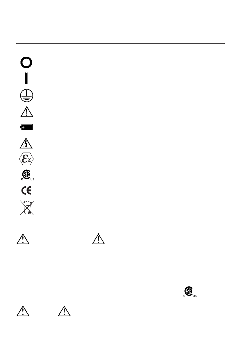
Symbols Used
The following table lists the International Electrical Symbols. Some or all of
these symbols may be used on the instrument or in this manual.
Symbol Description
Power OFF
Power ON
Earth ground
Risk of Danger. Important information. Refer to manual.
Battery
Hazardous Voltage
Conforms to ATEX requirements
Certified by CSA as conforming to relevant Canadian and USA standards
Conforms to relevant European Union directives.
Wheeled bin, conforms to EC directive 2002/96/EC
Hazard Location Information
Ex Hazardous Areas
An Ex-hazardous area as used in this manual refers to an area made
hazardous by the potential presence of flammable or explosive vapors.
These areas are also referred to as hazardous locations, see NFPA 70
Article 500 or CSA C22.1 Section 18.
Certification
This product is certified by CSA with the following rating:
Class I, Div. 2, Groups A-D
Misuse
Should the BetaGauge be exposed to overpressure or sudden physical
shock (i.e. being dropped) it should be examined for any damage that may
Page 4
cause a safety concern. If in doubt please return the unit for evaluation to
Ametek. Please refer to the Customer Service Section for contact
information.
Caution
To avoid possible damage to calibrator or to equipment under test:
• If the message changes to "OL" the range limit is exceeded and the
pressure source must immediately be removed from the IPI to prevent
damage to the pressure transducer inside.
• Maximum torque allowed is 13,5 Nm = 10 ftlbs. NEVER exceed the torque
allowed.
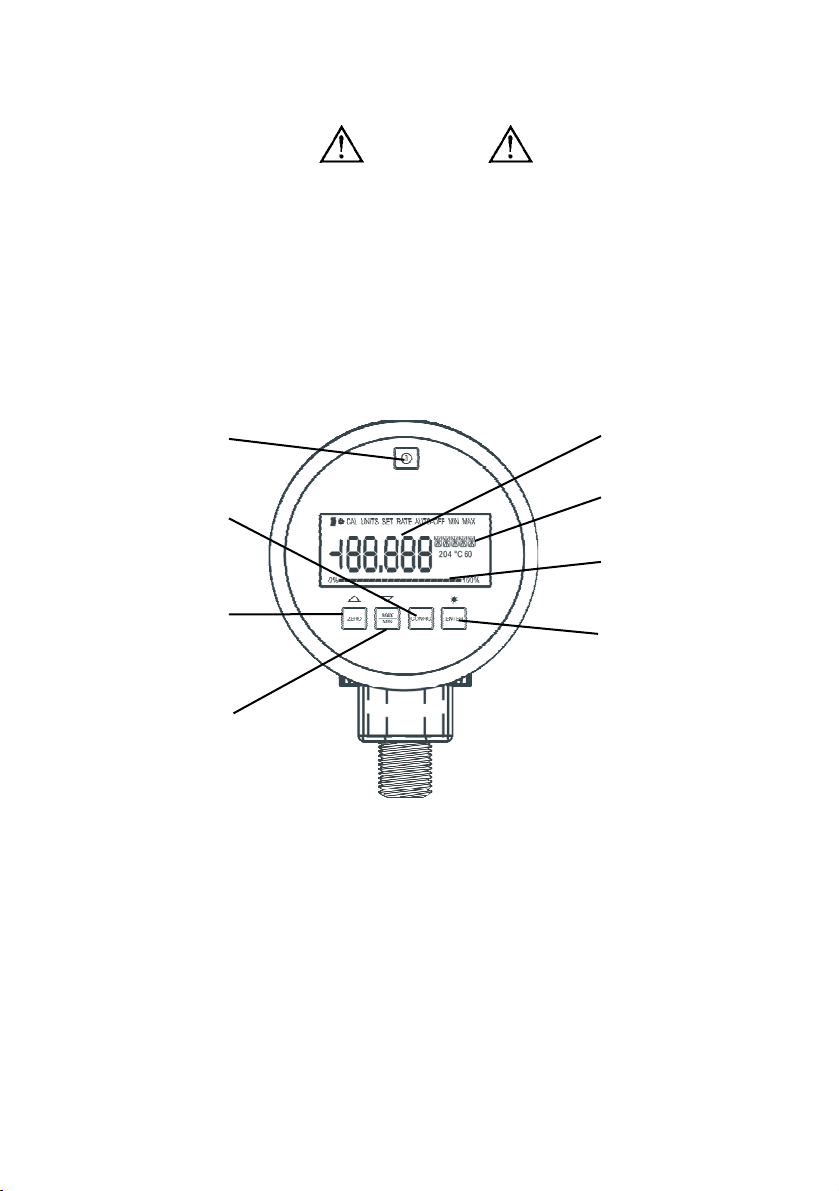
IPI Display and Controls
Operation
Power: The standard IPI is supplied with 3 AA batteries installed. If you
purchased the optional 24Volt powered version, batteries are not installed.
Connect a 24V power supply to the terminal block on the rear of the gauge,
noting proper polarity.
Do not install batteries when external power will be used.
Push the power button momentarily to turn the unit on. Push it again to turn
it off.
Set-up and configuration:
Push the CONFIG button to access the user-settable functions on the gauge.
Each time the CONFIG button is pressed; the display advances to the next
3
Pressure display
Engineering Units
0 - 100% bar graph
Selects an action in
configuration.
Also turns the
back-light on/off
Turns Power on/off
Enters set-up and
configuration menus
Zeros the display,
Scrolls forward through
menu displays
Recalls min and max
readings.
Scrolls backwards
through menu displays
Page 5

4
function. Once a function has been set, press ENTER to exit the
configuration menu, or CONFIG to continue with further configuration. In
order, the configuration menu and operation is as follows:
1. Engineering Units set. The unit is shipped configured to display
PSI. By pressing the ▲ and ▼ (ZERO and MAX/MIN) keys you can
scroll forward and backwards through the 18 standard engineering
units plus a one custom unit/scale. When the desired unit is displayed,
press ENTER or CONFIG. Pressure will now be displayed in the
chosen engineering units.
See the Specifications section of this manual for a list of available
engineering units. See the Supervisory Mode section for details on
setting up custom units.
2. Set Auto Off. The auto-shut off can be set in 1 minute increments
from 1 to 30 minutes or “off” (continuous operation). The unit is
shipped set for 30 minutes. Use the ▲ and ▼ keys to set the desired
interval. The “off” setting is at the low end of the choices, below 1
minute.
3. Display battery voltage. Actual voltage and a percent of life
bargraph indicate battery condition
4. Display actual temperature. The IPI is temperature compensated,
this displays the temperature measured by the internal sensor. The
value can be set to degrees F or degrees C using the arrow keys.
5. Set damping. Choices are “on” and “off” set with the ▲ and ▼ keys.
Turning damping on will smooth readings from pulsating pressure
sources.
6. Set sample rate: This determines how often pressure is sampled and
the display is updated. Choices are 0.5, 1, 3, and 10 samples/
second. Note that 10/sec provides the fastest response time.
7. Set TARE. This allows you to set a constant offset value, which is
then subtracted from the measured pressure. For example if a TARE is
set at 30 PSI, and the measured pressure is 37 PSI, the displayed
value will be 7 PSI.
A pressure of 27 PSI would be displayed as –3 PSI.
The tare value is set manually with the ▲ and ▼ keys, and is based on
the engineering units and resolution selected for display. TARE value
can be set to the maximum range of the gauge.
The bar graph will always display the actual pressure based on the full
range of the gauge regardless of the tare setting. This is done for
safety to insure that even with a “0” reading that pressure is being
applied to the gauge.
Page 6

8. Function Lock: Access to each of the settable parameters above can
be turned “off” once set, to prevent unauthorized changes to
configuration. This is accomplished through a password protected
“supervisory mode”. Press ENTER to access the supervisory mode, or
CONFIG to return to normal operation.
Supervisory Mode
Push the CONFIG button to access the user-settable functions on the
indicator. Each time the CONFIG button is pressed; the display advances
to the next function. Press CONFIG repeatedly until “FUnC LOCK” is
displayed.
Press ENTER when “FUnC LOCK” is displayed, 0
PWRD
will be displayed on
the gauge. The password to enter supervisory mode is 101, set using the
▲ and ▼ keys. Holding a key continuously will cause the display to
advance more quickly for faster setting. The password is factory set and
cannot be changed.
1. Your IPI is shipped from the factory with all setting access “unlocked”
or available to be changed.
2. In supervisory mode each of the parameters can be locked or
unlocked using the ▲ and ▼ keys. Select LOC (lock) for those
parameters you do not want to be accessible, and UnLOC (unlock) for
those can be accessed.
3.
In order, the functions that can be unlocked, locked or accessed are:
• Zero function (enable/disable)
• Set pressure units (enable/disable)
• Auto shutdown adjustment (enable/disable)
• Damping settings (enable/disable)
• Sample rate setting (enable/disable)
• Tare setting (enable/disable)
• Custom engineering units (set scale factor)
4. Use the CONFIG key to scroll through the above choices, and the ▲
and ▼ keys to lock and unlock features. Press CONFIG to continue
scrolling through the parameters, pressing ENTER at any point saves
your settings and returns the gauge to normal operation.
When a function is “locked”, it cannot be accessed or changed from
its current state. To change a locked function, enter the supervisory
mode, and unlock the function. Once it is changed, you may enter
supervisory mode to lock access again.
5. Setting a custom engineering unit or scale: The last menu choice in
supervisory mode is SET FACTR. This allows you to set a multiplier
5
Page 7

6
factor from 0.001 to 100, creating a custom scale. The set factor will
be multiplied by the PSI measured, the result will be displayed.
For example: 40 PSI is the equivalent of 1000 lbs of product in a tank.
You want to display the product weight , using a 100 PSI gauge. By
setting a factor of 25, a 40 PSI pressure would display as 1000 (40 x
25). The engineering unit displayed on the IPI will be “Cust”.
Normal Operation
Turning the backlight on and off: Press the ENTER button.
Zeroing the display: Press and hold the ZERO button.
MAX/MIN: The IPI stores minimum and maximum pressure values in
memory. Pressing the MAX/MIN button once will display the minimum
pressure from memory. Pressing the MAX/MIN button again will display
the maximum pressure from memory. After about 2 seconds, the gauge
returns to normal (live display) operation. To clear the MAX/MIN memory
registers, press and hold the MAX/MIN button for 2 or more seconds until
“CLr” is displayed.
The analog bar graph at the bottom of the display indicates the applied
pressure level relative to the full range of the gauge. Keep in mind that if a
TARE value has been programmed into the gauge, the displayed pressure
will not reflect the true pressure applied.
Changing the Batteries
WARNING
Explosion hazard
Batteries must only be changed in an area known
to be non-hazardous.
Grasp the face ring on the IPI, turn it approximately ¼ turn
counterclockwise and remove. The face of the gauge can now be lifted to
expose the battery holder. Take off the battery hold clip and remove the
batteries. Install three AA batteries noting proper polarity. Note: Use ONLY
AA size batteries and be sure to reinstall the battery holder retaining clip.
Reassemble the case making certain that the face is properly oriented.
If you purchased the optional 24 Volt powered version, the terminals for
power input are located on the rear of the gauge. To apply power simply
connect 24 volts to the rear terminal block taking care to observe proper
polarity.
Page 8

WARNING
Gauges ordered with the external power option will not come with
batteries installed. Batteries MUST NOT be installed when
operating on external power. External power option gauges are not
approved for hazardous location use.
Battery life
Battery life is about 1500 hours (60 days) of continuous use with the
backlight off. With intermittent use, batteries could last a year or more.
There is a low battery icon in the upper left of the display. It will appear
when battery level is low. Replace batteries per recommendations found in
the specifications section of this manual.
RS-232 Interface
An RS-232 interface is standard on the IPI. Serial communication can be
used for configuration, calibration, and to transfer measurement data from
the gauge. For detailed specifications on the interface and software
communication, contact the factory at 603-434-1433 and request a copy of
our interface manual.
WARNING
The RS-232 interface must not be used in hazardous areas.
CLEANING
To clean the BetaGauge use a cloth with a mild cleaning solution.
7
Page 9

8
Specifications
All specifications cover the temperature range from 0°C to +50°C, unless otherwise noted.
Available Input Ranges
See page 14 for a table of available ranges in PSI plus equivalent ranges
and resolution for all engineering units
Accuracy
Positive Pressure: ±0.05% FS
Vacuum: ±0.25% FS (500 PSI gauge ranges and below)
0.1% FS for 15/30 PSI compound/vacuum versions
For gauges with full scale ranges equal to, or less than 30 psi (2 BAR),
vacuum operation is limited to -5psi (-350 mBAR). The exception is the 30
PSI compound/vacuum model which will operate to –14.7 PSI.
Over Pressure Protection:
Ranges from 15 PSI to 500 PSI/1 to 35 bar: 3X input pressure range
1,000, 3,000, and 5,000 PSI/70 to 350 bar ranges: 2X input pressure range
10,000 PSI/700 bar: 1.5X input pressure range
Overload Alarm (indicate OL on display): 1.2X input pressure range
Temperature Compensation
0 °C to +50 °C (32 °F to +122 °F) to rated accuracy
Note: For temperatures from –10 °C to 0 °C and 50 °C to 55 °C add .005%
F.S./°C
Standard Engineering Units
PSI, Bar, kg/cm
2
, inH2O (4 °C, 20 °C or 60 °F),
ftH2O (4 °C, 20 °C or 60 °F), cmH2O (4 °C and 20 °C), mH2O (4 °C and 20 °C),
KPa, mBAR, inHg, mmHg, Torr
One custom unit (user programmable)
Media Compatibility
Liquids and gases compatible with 316 stainless steel
Environmental
Operating Temperature -10 °C to +55 °C
Storage -20 °C to +70 °C (-4 °F to +158 °F)
Humidity 10% to 95% RH Non-condensing
Pollution Degree II
Page 10

Mechanical
Dimensions 4.5” (diameter) x 2.2” (depth) x 5” (height)
Pressure Connection: ¼” NPT Male
Housing: Stainless steel, meets NEMA 4/IP65
Display
5-1/2 Digits, 0.65” (16.53 mm) high
20-Segment bar graph, 0 to 100%
Power
Battery three (3), size AA alkaline batteries, optional 24 VDC power.
Battery Life 1,500 hours without backlight, 2,000 hours at slow sample rate
Low Battery Indicator icon is displayed near the end of battery life
Approvals
Class I, Div. 2, Groups A-D CE approved
Appendix 1: IPI Calibration Procedure
Overview
Calibration adjustment of the IPI is performed electronically via internal
software with the case closed. There are no mechanical adjustments; all
calibration commands and adjustments are done via the keypad, using the
display to guide the user through the calibration process.
Eight calibration points are used in the adjustment program, working from
full scale to zero at pressures equaling 100%, 87.5%, 75%, 62.5%, 50%,
37.5%, 25%, 12.5%, and 0% of full scale plus vacuum.
Note: This is an ambient temperature calibration, and should be performed
at an ambient temperature of 23 °C ± 3 °C (72 °F ± 5 °F). Calibration
outside this temperature range will invalidate the temperature
compensation program in the IPI.
Calibration Interval
You should check performance of the PI at the interval required by your
calibration program. We recommend adjustment when measurement
deviates by more than 75% of the specified accuracy, or 0.04%
Test Equipment
Verification and calibration of the IPI requires pressure and/or vacuum
standards able to produce and indicate pressures from vacuum to the fullscale range of the unit under test. In order to maintain the specified
accuracy of the IPI, standards should have a TUR of 4:1 or better.
9
Page 11

10
Connections:
The PI uses a 1/4 NPT male connection in the pressure input port. Various
adapters may or may not be needed to connect to the pressure standard.
Always make sure the hose, tubing, and fittings etc have a rated working
pressure at or above the pressure of the unit. Also it is important that there
be no leaks when performing calibration; use Teflon tape where
appropriate.
Entering Calibration Mode:
After you have made your connections, turn the power on while holding the
CONFIG key. Use the arrow keys to enter the password. The password is
101. If you have entered calibration mode correctly the display should look
as shown below. The pressure value displayed will be the full-scale value
of the gauge.
Procedure:
Screens shown in this manual represent the displays shown with a 500 psi
Gauge. The IPI will prompt the technician for the appropriate pressure at
each calibration point.
Use the Pressure Standard to output 500.00 psi (100%). After the output
has stabilized, press the ENTER key to continue. As the unit takes
readings, the screen will show ———-. When the readings are complete
the screen should look as shown in the illustration that follows.
Use the Pressure Standard to output 437.50 psi (87.5%). After the output
has stabilized, press the ENTER key to continue. As the unit takes
readings, the screen will show ———-. When the readings are complete
the screen should look as shown below.
PSI
437.50
CAL MODE
PSI
375.00
CAL MODE
PSI
500.00
CAL MODE
Page 12

Use the Pressure Standard to output 375.00 psi (75%). After the output
has stabilized, press the ENTER key to continue. As the unit takes
readings, the screen will show ———-. When the readings are complete
the screen should look as shown below.
Use the Pressure Standard to output 312.50 psi (62.5%). After the output
has stabilized, press the ENTER key to continue. As the unit takes
readings, the screen will show ———-. When the readings are complete
the screen should look as shown below.
Use the Pressure Standard to output 250.00 psi (50%). After the output
has stabilized, press the ENTER key to continue. As the unit takes
readings, the screen will show ———-. When the readings are complete
the screen should look as shown below.
Use the Pressure Standard to output 187.50 psi (37.5%). After the output
has stabilized, press the ENTER key to continue. As the unit takes
readings, the screen will show ———-. When the readings are complete
the screen should look as shown below.
Use the Pressure Standard to output 125.00 psi (25%). After the output
has stabilized, press the ENTER key to continue. As the unit takes
11
PSI
250.00
CAL MODE
PSI
187.50
CAL MODE
PSI
125.00
CAL MODE
PSI
312.50
CAL MODE
Page 13

12
readings, the screen will show ———-. When the readings are complete the
screen should look as shown below.
Use the Pressure Standard to output 62.50 psi (12.5%). After the output has
stabilized, press the ENTER key to continue. As the unit takes readings, the
screen will show ———-. When the readings are complete the screen
should look as shown below.
Use the Pressure Standard to output 0.00 psi. After the output has
stabilized, press the ENTER key to continue. As the unit takes readings, the
screen will show ———-. When the readings are complete the screen
should look as shown below.
Note: Only some ranges use vacuum calibration. If your gauge is not one,
than this step will be automatically skipped and calibration will be complete.
Use the Pressure Standard to output -12.00 psi. After the output has
stabilized, press the ENTER key to continue. As the unit takes readings, the
screen will show ———-. When the readings are complete the unit will
reset and power up in normal mode.
Service Center Calibration or Repair
Only qualified service personnel should perform calibration, repairs, or
servicing not covered in this manual. If the calibrator fails, check the
batteries first, and replace them if needed.
Verify that the calibrator is being operated as explained in this manual. If the
calibrator is faulty, send a description of the failure with the calibrator. Be
sure to pack the calibrator securely, using the original shipping container if it
is available.
PSI
-12.00
CAL MODE
PSI
62.50
CAL MODE
PSI
0.00
CAL MODE
Page 14

13
PSI Ranges
Eng. Units 15 30 100 300 500 1000 2000 3000 5000 10000
psi 15.000 30.000 100.00 300.00 500.00 1000.0 2000.0 3000.0 5000.0 10000
bar 1.0342 2.0684 6.8947 20.684 34.474 68.947 137.89 206.84 344.74 689.47
mbar 1034.2 2068.4 6894.8 20684 34474 68948 NA NA NA NA
kPa 103.42 206.84 689.48 2068.4 3447.4 6894.8 13790 20684 34474 68948
kg/cm
2
1.0546 2.1092 7.0307 21.092 35.153 70.307 140.61 210.92 351.53 703.07
cmH
2
O@4°C 1054.6 2109.3 7030.9 21093 35154 70309 NA NA NA NA
cmH
2
O@20°C 1056.5 2113.0 7043.4 21130 35217 70434 NA NA NA NA
mH
2
O@4°C 10.546 21.093 70.309 210.93 351.54 703.09 1406.2 2109.3 3515.4 7030.9
mH
2
O@20°C 10.565 21.130 70.434 211.30 352.17 704.34 1408.7 2113.0 3521.7 7043.4
inH
2
O@4°C 415.21 830.42 2768.1 8304.2 13840 27681 55361 83042 NA NA
inH
2
O@20°C 415.95 831.89 2773.0 8318.9 13865 27730 55460 83189 NA NA
inH
2
O@60°F 415.61 831.23 2770.8 8312.3 13854 27708 55415 83123 NA NA
mmHg@0°C 775.73 1551.5 5171.5 15515 25858 51715 NA NA NA NA
inHg@0°C 30.540 61.081 203.60 610.81 1018.0 2036.0 4072.0 6108.1 10180 20360
ftH2O@4°C 34.601 69.202 230.67 692.02 1153.4 2306.7 4613.5 6920.2 11534 23067
ftH2O@20°C 34.662 69.324 231.08 693.24 1155.4 2310.8 4621.6 6932.4 11554 23108
ftH2O@60°F 34.634 69.269 230.90 692.69 1154.5 2309.0 4617.9 6926.9 11545 23090
Torr 775.73 1551.5 5171.5 15515 25858 51715 NA NA NA NA
Available Ranges and Resolution by Engineering Unit
Page 15

P/N 0219225 Rev. B 08/05
Page 16

AMETEK is a leading global manufacturer of electrical and electromechanical products for niche markets. Listed on the New York Stock Exchange (AME)
since 1930. AMETEK’s annual sales exceed $1 billion. Operations are in North America, Europe, and Asia, with about one third of sales to markets outside
the United States.
CALIBRATION INSTRUMENTS
AMETEK Test & Calibration Instruments • Florida, USA (Western Hemisphere)
Tel: +1 727-536-7831 • Tel: +1 800-527-9999 • calinfo.us@ametek.com
AMETEK Denmark A/S • Denmark (Europe and the Middle East)
Tel: +45 4816 8000 • ametek@ametek.dk
AMETEK Precision Instruments Europe GmbH • Germany (Germany only)
Tel: +49 2159 91360 • info@ametek.de
AMETEK Singapore Pte. Ltd. • Singapore (Asia)
Tel: +65 6 484 2388 • aspl@ametek.com.sg
w ww.ame tekca libra tion. com
w ww.jof ra.co m
Information within this document is
subject to change without notice.
All rights reserved.
...because calibration is
a matter of condence
AMETEK
Calibration Instruments
offers a complete range of calibration equipment for
pressure, temperature, and signal - including software.
JOFRA Temperature standards
Portable precision thermometer. Dry-block calibrators:
4 series, more than 20 models - featuring speed,
portability, accuracy, and advanced documenting functions.
M&G Primary pressure standards
Pneumatic floating-ball or hydraulic piston deadweight testers
- easy-to-use with accuracies up to 0.015% of reading.
JOFRA Pressure standards
Convenient electronic systems ranging from -1 to 700 bar
(25 inHg to 10,000 psi) - multiple choices of pressure ranges,
pumps, and accuracies, fully temperature-compensated
for problem-free and accurate field use.
JOFRA Signal calibration
Process signal measurement and simulation
for easy control loop calibration and measurement tasks -
from handheld field instruments for multi or single
signals to laboratory reference level bench top instruments.
 Loading...