

Page 1
iPac® Pachymeter
User’s Guide
Page 2

©2017 AMETEK, Inc.
iPac, Reichert and Reichert Technologies are registered trademarks of Reichert, Inc.
The Bluetooth word mark, figure mark, and combination mark are registered trademarks owned
by Bluetooth SIG.
AMETEK is a registered trademark of AMETEK, Inc.
The information contained in this document was accurate at time of publication.
Reichert, Inc. reserves the right to make changes in the product described in this manual without
notice and without incorporating those changes in any products already sold.
ISO 9001/13485 Certified – Reichert products are designed and manufactured under quality
processes meeting ISO 9001/13485 requirements.
No part of this publication may be reproduced, stored in a retrieval system, or transmitted in any
form or by any means, electronic, mechanical, recording, or otherwise, without the prior written
permission of Reichert, Inc.
Caution: Federal law restricts this device to sale by or on the order of a
licensed physician. Rx Only.
Page 3

16040-101 Rev. J 3
Table of Contents
Warnings and Cautions ........................................................... 4
Symbol Information.................................................................. 7
Introduction .............................................................................. 8
Instrument Setup .....................................................................10
Unpacking Instructions ........................................................10
Parts Identication ...............................................................11
Accessories .........................................................................11
Optional Accessories ...........................................................11
Icon Description ...................................................................12
Charging the iPac Pachymeter ............................................ 13
Power Up Mode ...................................................................14
Measurement Mode ............................................................14
Sleep Mode .........................................................................14
iPac Setup Menu .................................................................15
iPac Menu Options .............................................................17
Bluetooth ..........................................................................17
About ................................................................................18
Date/Time .........................................................................19
Display ..............................................................................20
Instrument Operation ...............................................................21
Measurement Screen ..........................................................21
Operation .............................................................................23
Operational Check ...............................................................23
Patient Preparation ..............................................................23
Measurement Process ........................................................24
Bluetooth Printing ................................................................26
iPac Bluetooth Printer ..........................................................27
Cleaning and Disinfection .......................................................28
iPac Cleaning Instructions ...................................................28
Measurement Tip Cleaning Instructions ..............................28
Measurement Tip High Level Disinfection Instructions ...... 29
Maintenance and Storage .......................................................30
General Maintenance ..........................................................30
Battery .................................................................................30
Storage ................................................................................30
Troubleshooting .......................................................................31
Specications ..........................................................................32
Disposal ...............................................................................32
Software Revision ...............................................................32
Guidance & Manufacturer’s Declaration .................................. 33
Regulatory Compliance - Bluetooth ......................................... 37
Acoustic Output .......................................................................38
Warranty ..................................................................................40
Appendix A...............................................................................41
Page 4

4 16040-101 Rev. J
Warnings and Cautions
WARNING: AN INSTRUCTION THAT DRAWS ATTENTION TO RISK OF INJURY OR DEATH.
WARNING: UNITED STATES FEDERAL LAW AND EUROPEAN REGULATIONS REQUIRE THAT
THIS DEVICE BE PURCHASED ONLY BY A PHYSICIAN OR A PERSON ACTING ON BEHALF OF
A PHYSICIAN. ONLY USERS TRAINED IN THE USE OF OPHTHALMIC INSTRUMENTS THAT
CONTACT THE EYE SHOULD USE THIS DEVICE. REICHERT TECHNOLOGIES CANNOT BE HELD
RESPONSIBLE FOR ANY DAMAGE OR INJURY THAT RESULTS FROM A FAILURE TO FOLLOW
DIRECTIONS IN THE USER’S MANUAL. PLEASE ENSURE THAT YOU ARE ENTIRELY FAMILIAR
WITH THE CORRECT PROCEDURES FOR OPERATING THE INSTRUMENT BEFORE USE.
WARNING: THIS INSTRUMENT SHOULD BE USED IN STRICT ACCORDANCE WITH THE
INSTRUCTIONS OUTLINED IN THIS USER’S GUIDE. THE SAFETY OF THE OPERATOR AND THE
PERFORMANCE OF THE INSTRUMENT CANNOT BE GUARANTEED IF USED IN A MANNER NOT
SPECIFIED BY REICHERT TECHNOLOGIES.
WARNING: DO NOT REPAIR OR SERVICE THIS INSTRUMENT WITHOUT AUTHORIZATION FROM
THE MANUFACTURER. ANY REPAIR OR SERVICE TO THIS INSTRUMENT MUST BE PERFORMED
BY EXPERIENCED PERSONNEL OR DEALERS WHO ARE TRAINED BY REICHERT OR SERIOUS
INJURY TO THE OPERATOR OR PATIENT MAY OCCUR.
WARNING: MODIFICATIONS TO THIS INSTRUMENT ARE NOT ALLOWED. ANY MODIFICATION TO
THIS UNIT MUST BE AUTHORIZED BY REICHERT OR SERIOUS INJURY TO THE OPERATOR OR
PATIENT MAY OCCUR.
WARNING: ENSURE THAT THE VOLTAGE APPLIED TO THE UNIT IS THE SAME AS THE
VOLTAGE THAT IS INDICATED ON THE DATA PLATE OR DAMAGE TO THE UNIT MAY OCCUR.
WARNING: THIS INSTRUMENT IS NOT SUITABLE FOR USE IN THE PRESENCE OF FLAMMABLE
ANESTHETIC MIXTURES, SUCH AS OXYGEN OR NITROUS OXIDE.
WARNING: THE BATTERY SHOULD ONLY BE REPLACED WITH THE BATTERY SPECIFIED IN
THIS MANUAL. USE OF ANOTHER BATTERY MAY CAUSE FIRE OR AN EXPLOSION.
WARNING: AFTER EACH PATIENT, PERFORM THE CLEANING INSTRUCTIONS AS INDICATED IN
THE CLEANING SECTION OF THIS MANUAL.
WARNING: THE BATTERY SHOULD ONLY BE REPLACED WITH THE BATTERY SPECIFIED IN THIS
MANUAL. USE OF ANOTHER BATTERY MAY CAUSE FIRE OR AN EXPLOSION.
WARNING: DO NOT USE THE IPAC PACHYMETER IF THE MEASUREMENT TIP IS CRACKED,
CHIPPED OR SHOWS ANY IRREGULARITY OF THE SURFACE, TO PREVENT PATIENT INJURY
AND OR INACCURATE READINGS.
WARNING: IF THIS INSTRUMENT IS MODIFIED, APPROPRIATE INSPECTION AND TESTING
MUST BE CONDUCTED TO ENSURE CONTINUED SAFE USE OF THIS INSTRUMENT.
WARNING: DO NOT EXPOSE THE BATTERIES TO TEMPERATURES ABOVE 140ºF, DISASSEMBLE
THE BATTERIES, OR DAMAGE TO THIS UNIT AND/OR SERIOUS PERSONAL INJURY MAY RESULT.
Page 5

16040-101 Rev. J 5
Warnings and Cautions (continued)
WARNING: DO NOT PLACE A SHORTING DEVICE BETWEEN THE BATTERY TERMINALS, OR
ALLOW THE BATTERY TO BECOME WET. MISUSE OR IMPROPER DISPOSAL OF THIS BATTERY
MAY CAUSE IT TO BECOME VERY HOT, IGNITE OR EXPLODE. DAMAGE TO THIS UNIT AND/OR
SERIOUS PERSONAL INJURY MAY RESULT.
WARNING: ALWAYS KEEP BATTERIES OUT OF THE REACH OF INFANTS AND YOUNG CHILDREN
TO PREVENT THEM FROM BEING SWALLOWED. IF SWALLOWED, CONSULT A PHYSICIAN
IMMEDIATELY.
WARNING: NEVER ALLOW LIQUID LEAKING FROM THE BATTERY TO GET IN YOUR EYES OR
MOUTH AS THIS LIQUID COULD CAUSE SERIOUS PERSONAL INJURY. IF IT COMES IN CONTACT
WITH YOUR EYES OR MOUTH, FLUSH THEM IMMEDIATELY WITH PLENTY OF WATER AND
CONSULT A PHYSICIAN.
WARNING: IN ORDER TO PREVENT PATIENT-TO-PATIENT TRANSFER OF INFECTION, AFTER
EACH USE DISINFECT THE MEASUREMENT TIP FOLLOWING ACCEPTED LOCAL CLINICAL PRO
CEDURES REGARDING THE USE OF DISINFECTANTS. ANY CLINICALLY APPROVED CHEMICAL
DISINFECTANT CAN BE USED.
WARNING: MEASUREMENTS SHOULD NOT BE ATTEMPTED WHEN OCULAR INTEGRITY IS
QUESTIONABLE. THE HANDHELD TRANSDUCER MUST TOUCH THE EYE DURING OPERATION.
CONSEQUENTLY, THE USER NEEDS TO EXHIBIT CARE IN MANIPULATING THE TRANSDUCER.
FORCE SHOULD NOT BE EXERTED AGAINST THE EYE – THE TRANSDUCER TIP ONLY NEEDS
TO LIGHTLY TOUCH THE CORNEA.
WARNING: TO ENSURE PATIENT ISOLATION FROM HIGH ELECTRICAL POTENTIAL, DO NOT USE
THE IPAC ON A PATIENT WHEN THE INSTRUMENT IS CHARGING. IPAC CHARGING MUST ONLY
TAKE PLACE AT A DISTANCE OF AT LEAST 1.5 M FROM THE PATIENT.
WARNING: IT IS PRUDENT TO MINIMIZE THE PATIENT’S EXPOSURE TO ULTRASOUND ENERGY
TO A LEVEL AS LOW AS REASONABLY ACHIEVABLE (ALARA) BY REDUCING THE NUMBER OF
SCANS NEEDED TO BE PERFORMED. ADVISE THE PATIENT OF WHAT TO EXPECT DURING A
SCAN TO REDUCE REPETITIVE SCANS. THE AMERICAN INSTITUTE OF ULTRASOUND IN MEDI
CINE (AIUM) HAS A PUBLICATION “MEDICAL ULTRASOUND SAFETY” (1994) WHICH HAS MORE
INFORMATION ON THIS TOPIC.
CAUTION: AN INSTRUCTION THAT DRAWS ATTENTION TO THE RISK OF DAMAGE TO
THE PRODUCT.
CAUTION: DO NOT IMMERSE THE IPAC PACHYMETER IN FLUIDS OR DAMAGE TO THE ELEC
-
TRONICS MAY OCCUR.
CAUTION: DO NOT ATTEMPT TO MODIFY THE IPAC PACHYMETER OR PATIENT INJURY, AND/OR
INACCURATE READINGS MAY OCCUR.
CAUTION: THIS DEVICE HAS NOT BEEN TESTED IN CONJUNCTION WITH HF SURGICAL (E.G.
ELECTROCAUTERY) EQUIPMENT AND SHOULD NOT BE USED WITH SUCH EQUIPMENT.
Page 6

6 16040-101 Rev. J
Warnings and Cautions (continued)
CAUTION: THE INTERNAL CIRCUITRY OF THE INSTRUMENT CONTAINS ELECTROSTATIC
DISCHARGE SENSITIVE DEVICES (ESDS) THAT MAY BE SENSITIVE TO STATIC CHARGES
PRODUCED BY THE HUMAN BODY. DO NOT REMOVE THE COVERS WITHOUT TAKING PROPER
ESDS PRECAUTIONS.
CAUTION: THIS INSTRUMENT IS NOT INTENDED TO BE CONNECTED TO EQUIPMENT OUTSIDE
THE CONTROL OF REICHERT INC. OR MUST BE TESTED TO AN APPLICABLE IEC OR ISO
STANDARDS.
CAUTION: DO NOT USE SOLVENTS OR STRONG CLEANING SOLUTIONS ON ANY PART OF
THIS INSTRUMENT AS DAMAGE TO THE UNIT MAY OCCUR. SEE MAINTENANCE SECTION FOR
DETAILED CLEANING INSTRUCTION.
CAUTION: DO NOT AUTOCLAVE OR DISINFECT USING HIGH TEMPERATURES EXCEEDING
THE RECOMMENDED TEMPERATURES INDICATED IN THE SPECIFICATIONS SECTION OF THIS
MANUAL OR DAMAGE TO THE UNIT MAY OCCUR.
CAUTION: DO NOT ATTEMPT INTERNAL STERILIZATION OF IPAC OR DAMAGE TO THE ELEC
-
TRONICS MAY OCCUR.
CAUTION: USE OF AMMONIA BASED CLEANERS ON THE DISPLAY (OLED) MAY CAUSE DAMAGE
TO THE DISPLAY. SEE MAINTENANCE SECTION FOR DETAILED CLEANING INSTRUCTION.
CAUTION: MEDICAL ELECTRICAL EQUIPMENT NEEDS SPECIAL PRECAUTIONS REGARDING
EMC AND NEEDS TO BE INSTALLED AND PUT INTO SERVICE ACCORDING TO THE EMC INFORMATION PROVIDED IN THIS GUIDE. PORTABLE AND MOBILE RF COMMUNICATIONS EQUIPMENT
CAN AFFECT MEDICAL ELECTRICAL EQUIPMENT.
CAUTION: ELECTROMAGNETIC INTERFERENCE FROM OTHER DEVICES MAY AFFECT THIS
INSTRUMENT. IF INTERFERENCE IS PRESENT, TURN OFF OTHER ELECTRONIC DEVICES, OR
REMOVE THEM FROM THE IMMEDIATE AREA WHILE OPERATING THIS INSTRUMENT.
CAUTION: ALWAYS ENSURE THE IPAC IS CHARGED SUFFICIENTLY OR ERRATIC READINGS
MAY OCCUR. USE ONLY THE SUPPLIED CHARGER PROVIDED WITH THE UNIT. IT IS RECOMMENDED THAT THE IPAC BE ATTACHED TO ITS CHARGER (OR CHARGING BASE) WHEN NOT IN
USE TO ENSURE PROPER OPERATION.
CAUTION: DO NOT ATTEMPT TO CHARGE THE IPAC OR POWER THE CHARGING CRADLE USING THE USB PORT OF A COMPUTER OR DAMAGE TO THE IPAC OR COMPUTER MAY OCCUR.
Page 7
16040-101 Rev. J 7
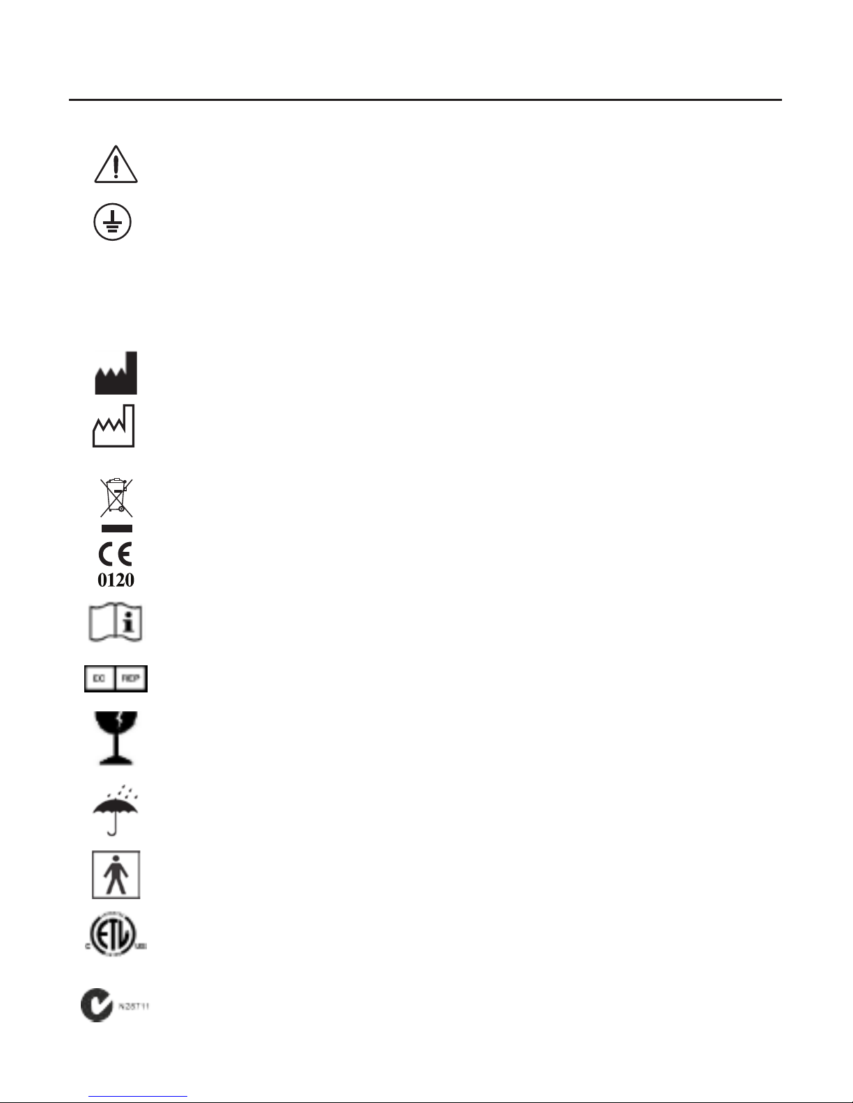
Symbol Information
Caution
Protective Earth - Indicates that a protective earth ground is connected
where the symbol is located.
REF
Catalog Number
SN
Serial Number
Manufacturer
2017
Date of Manufacture
Waste of Electrical and Electronic Equipment
Compliance to Medical Device Directive 93/42/EEC
Consult Instructions for Use - Indicates that important operating and
maintenance instructions are included in this User’s Guide.
Authorized Representative in European Community
Fragile Contents in Shipping Container - handle with care
Keep Dry - Package shall be kept away from rain.
Type BF Product Classification.
Authorized to mark given by Intertek ETL Semko for conformance with
electrical standards.
C-Tick mark for ACMA in Australia Trade Marks Act 1995 and RSM in
New Zealand under section 47 of the New Zealand Trademarks Acts.
Page 8

8 16040-101 Rev. J
Introduction
Congratulations on your purchase of the Reichert® iPac® Pachymeter.
This User’s Guide is designed as a training and reference manual for operation,
maintenance, and troubleshooting. We recommend that you read it carefully prior
to use and follow the instructions in the guide to ensure optimum performance of
your new instrument. If used properly, the iPac Pachymeter will provide you with
fast, accurate and reliable measurements for many years. Properly trained eyecare
professionals such as ophthalmologists, optometrists, opticians and eye care
technicians should operate this instrument.
Please retain this manual for future reference and to share with other users. Additional
copies can be obtained from the Reichert Customer Service Department. Contact
information is provided at the end of this guide.
Intended Use
The iPac Pachymeter is intended to measure thickness of the cornea in the human
eye using ultrasound energy.
Indications for Use
The indications for use is to measure the thickness of the cornea.
Contraindications
None.
Device Description
The iPac Pachymeter is an ergonomic, hand-held Pachymeter that measures central
corneal thickness. The body of the instrument is designed to fit comfortably in the
user’s hand, facilitating fast and accurate measurements. The tip of the Pachymeter
contains a sensor which measures central corneal thickness. The electronics
housed in the ergonomic iPac Pachymeter body process and analyze the waveforms
produced by each measurement of the corneal thickness of the eye. These are used
to produce an averaged pachymetry measurement. The measurement is displayed on
the Organic Light Emitting Diode (OLED) display.
A rechargeable battery is used in the iPac Pachymeter and consists of a lithium ion
battery.
-continued-
Page 9

16040-101 Rev. J 9
Introduction (continued)
Features
The iPac Pachymeter has the following features:
• Easy to Use - corneal thickness can be measured accurately by medical eye care
professionals.
• Portable - The iPac Pachymeter weighs just 3.53 oz. (100 g) and is rechargeable.
• Versatile - The iPac Pachymeter may be used easily with the patient in any
position, making the instrument suitable for the ofce, in clinics, at the hospital
bedside, and in remote locations.
• Bluetooth
®
Technology - wireless connectivity enabling communication to associ-
ated remote devices.
• OLED Color Display - Intuitive graphical display for ease of use.
Device Regulatory Classification
• Insulation Protection Class II
• Ingress Protection IPX1
• Applied Part Type BF
• Operation Mode Continuous
Page 10
10 16040-101 Rev. J
Instrument Setup
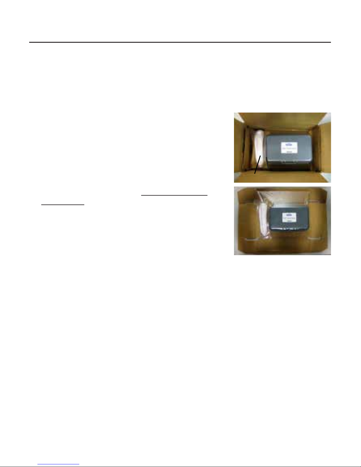
Unpacking Instructions
Great care has been taken to deliver your iPac Pachymeter to you. The packaging
was specifically designed to transport this instrument. Please retain the packaging for
future use in case transportation is required.
Removing the iPac Pachymeter
1. Lift the insert that contains the Carrying Case and
iPac Charging Cradle out of the box.
2. Unfold the insert and slide the Carrying Case and
iPac Charging Cradle out of the insert.
3. Open the carrying case, remove the User’s Guide
and read the instructions carefully.
4. Remove the iPac from the case, and charge the
instrument according to the Charging the iPac
Pachymeter section.
5. Store the box and insert in a safe place so that if it
is needed for future shipping, it will be available.
The items listed below should be included in the iPac
Pachymeter packaging:
• Carrying Case
• iPac Pachymeter
• Lanyard
• Tip Cover
• User’s Guide
• Battery (in the iPac)
• A/C Adapter w/ Mini USB
• iPac Pachymeter Charging Cradle
Note: If any of these items are missing, please contact the Reichert Customer
Service Department. Contact information can be found on the back cover of
this User’s Guide.
Carrying
Case
Shipping Box
iPac Charging Cradle
Shipping Box & Insert
Insert
Page 11
16040-101 Rev. J 11
Instrument Setup (continued)
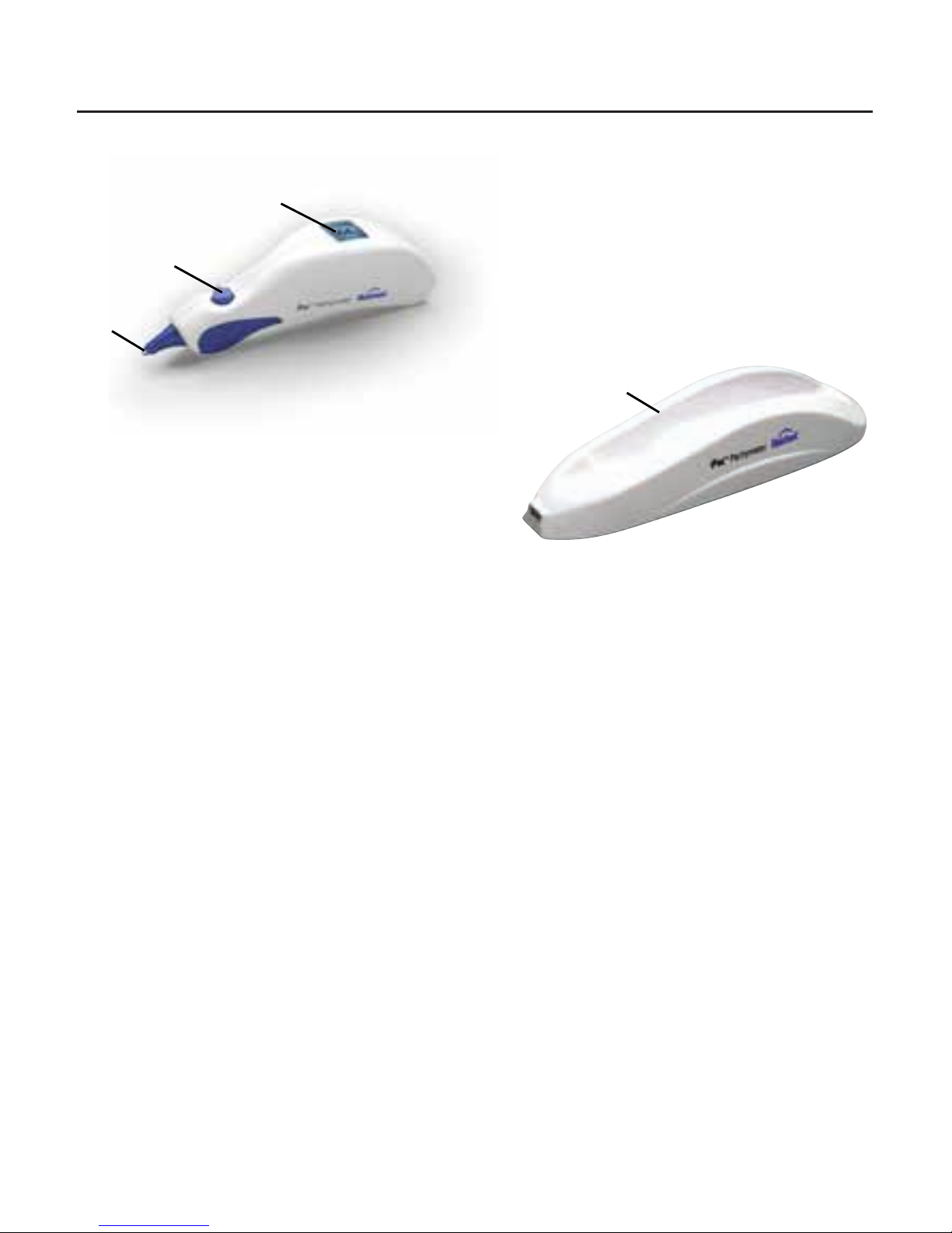
Parts Identification
1. Pachymeter
2. Measurement Tip
3. Control button
4. OLED Display
5. iPac Pachymeter Charging Cradle
Accessories & Spare Parts
User Guide (P/N 16040-101)
Carrying Case (P/N 16040-380)
Lanyard (P/N 13851-096)
Measurement Tip Cover (P/N 16040-027)
iPac Rechargeable Lithium Ion Battery (P/N 16042)
iPac Pachymeter Charging Cradle (P/N 16041)
A/C Adapter w/ Mini USB (P/N 16040-430) Including Country Specic Pin Connector*:
• North America (P/N 16040-410-001)
• Australia (P/N 16040-410-002)
• United Kingdom, Hong Kong, Singapore (P/N 16040-410-003)
• European Union, South America (P/N 16040-410-004)
• Korea (P/N 16040-410-005)
• Argentina (P/N 16040-410-006)
• China (P/N 16040-410-007)
• India (P/N 16040-410-008)
Optional Accessories
iPac Bluetooth Printer (P/N 16043)
Spare Printer Paper (5 pack) (P/N 12441)
* When ordering a replacement A/C Adapter, the corresponding Country Specic
Pin must be orders as well.
1
4
3
2
iPac Pachymeter
iPac Pachymeter
Charging Cradle
5
Page 12

12 16040-101 Rev. J
Instrument Setup (continued)
Icon Description
Move the Control button forward to go UP
Move the Control button back to go DOWN
Move the Control button left to go LEFT
Move the Control button right to go RIGHT
Press and hold the Control button for the indicated time
Press the Control button once and then release it
Bluetooth ON, but not connected
Bluetooth ON, Bluetooth Connected
Printer Connected
Printer Not Connected
Clear
Battery Requires Charging
Battery Low Power
Battery Fully Charged
Battery Charging
Page 13
16040-101 Rev. J 13
Instrument Setup (continued)
Charging the iPac Pachymeter
WARNING: CARE MUST BE TAKEN TO ARRANGE THE CABLES FOR THE
ACCESSORIES SUCH THAT THEY DO NOT PRESENT A TRIPPING HAZARD TO THE
EXAMINER OR A DANGER TO THE PATIENT.
WARNING: POSITION THIS INSTRUMENT SO THAT IT IS NOT DIFFICULT TO OPERATE
THE DISCONNECTION DEVICE (PLUG).
CAUTION: USE ONLY THE SUPPLIED CHARGER PROVIDED WITH THE UNIT. IT IS
RECOMMENDED THAT THE IPAC BE ATTACHED TO ITS CHARGER (OR CHARGING
BASE) WHEN NOT IN USE TO ENSURE PROPER OPERATION.
CAUTION: DO NOT ATTEMPT TO CHARGE THE IPAC OR POWER THE CHARGING
CRADLE USING THE USB PORT OF A COMPUTER OR DAMAGE TO THE IPAC OR
COMPUTER MAY OCCUR.
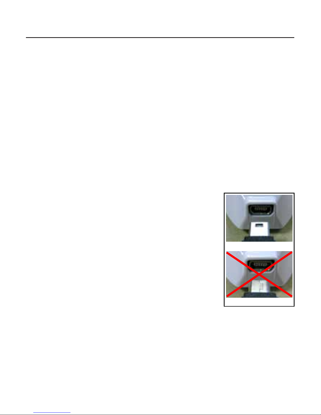
The iPac can be charged directly with the Charging Cradle or the A/C adaptor. In
either case, it is important to be sure that the Mini USB Plug is correctly oriented to the
Mini USB Port, either on the iPac or the Charging Cradle.
With a Charging Cradle
Note: Initially charge the unit for 10 hours.
Note: The Mini USB Port and the Mini USB Plug have a at
side and a curved side. The at side of the Plug has a
small rectangular cutout visible from the at side. When
connecting the Plug to the Port, be sure that the at side
of the Plug is lined up with the at side of the Port.
CAUTION: IF THE MINI USB PLUG IS NOT ALIGNED
PROPERLY WITH THE MINI USB PORT, THE PORT MAY BREAK
OFF AND THE PLUG MAY BECOME DAMAGED.
Note: It is important to initially charge the iPac Pachymeter
for the recommended period of time to ensure correct
operation.
Note: The iPac comes with a mini USB port cap installed in the mini USB port hole.
This should remain in the iPac to help ensure the iPac properly sits on the cradle.
1. Plug the A/C Adaptor with Mini USB into an appropriately volted outlet.
2. Connect the Mini USB charging cord to the Charging Cradle.
3. Place the iPac on the Charging Cradle.
-continued-
Correct
Incorrect
Plug
Port
Plug
Port
With Charging
Cradle
Page 14
14 16040-101 Rev. J
Instrument Setup (continued)
Charging the iPac Pachymeter (continued)
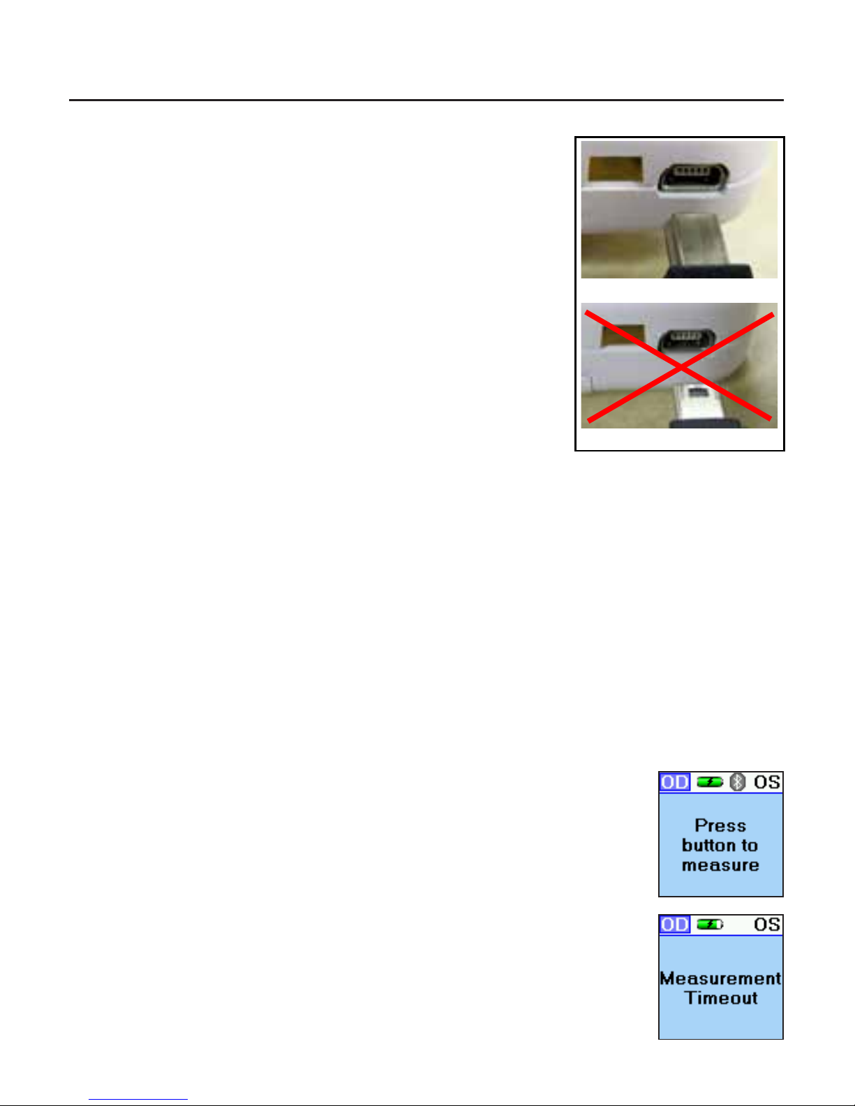
Without a Charging Cradle
Note: Initially charge the unit for 10 hours.
Note: The Mini USB Port and the Mini USB Plug have
a at side and a curved side. The at side of the
Plug has a small rectangular cutout visible from the
at side. When connecting the Plug to the Port, be
sure that the at side of the Plug is lined up with the
at side of the Port.
CAUTION: IF THE MINI USB PLUG IS NOT ALIGNED
PROPERLY WITH THE MINI USB PORT, THE PORT MAY
BREAK OFF AND THE PLUG MAY BECOME DAMAGED.
Note: It is important to initially charge the iPac
Pachymeter for the recommended period of time to
ensure correct operation.
Note: The iPac comes with a mini USB port cap installed in the mini USB port hole.
This needs to be removed before charging directly.
1. Plug the A/C Adaptor with Mini USB into an appropriately volted outlet.
2. Connect the Mini USB charging cord to the iPac Pachymeter.
Power Up Mode
Pressing the Control button initiates the iPac, the display will show “Press button to
measure,” after about one minute of inactivity, the iPac will go into sleep mode, the
display will turn off. To wake up the iPac press the control button and the display will
light up.
Measurement Mode
In this mode the iPac has about 15 seconds to start the measurement
process, if no measurements are taken then the display will show
“Measurement Timeout” and then revert back to the “Press button to
measure” display.
Sleep Mode
The iPac will automatically go into a power saving sleep mode after
a period of inactivity, the display will turn off. Press the control button
to exit the sleep mode and resume operation. There is no ON/OFF
switch on this instrument.
Correct
Incorrect
Plug
Port
Plug
Port
Without Charging
Cradle
Page 15

16040-101 Rev. J 15
iPac Setup Menu
The iPac setup menu enables the user to select the options that are preferred when
using the pachymeter. Press and hold (
)the Control button for three seconds to
display the Setup menu.
At the top of the Display is a menu title (e.g., SETUP). If there is a small arrow on
the left or right, moving the Control button LEFT or RIGHT will navigate through the
menu screens in accordance with the arrows. Selecting the LEFT arrow displays the
previous menu screen. Selecting the RIGHT arrow displays the highlighted selection.
Selecting options in the menu screens is performed by moving the Control button UP,
DOWN, LEFT, or RIGHT until the desired option is selected (highlighted). Press (
)
the Control button to activate the desired option.
The iPac SETUP screens are the following:
• Bluetooth
• Date/Time
• Display
• About
• Exit
In the Setup menus there are options that will have specific colored indicator icons.
The colors are:
Green Icon - Indicates this option is turned On.
Gray Icon - Indicates this option is turned Off.
Yellow Icon - Indicates this option is in the process of turning On.
Instrument Setup (continued)
Page 16

16 16040-101 Rev. J
iPac Setup Menu (continued)
Bluetooth
The Bluetooth screen has three options:
• Bluetooth - Press the control button to turn the Bluetooth
option ON or OFF.
• Search - Highlight the search option and press the control
button to nd any Bluetooth printer in the immediate area such
as the iPac Bluetooth printer. The display will show the devices
that have been discovered. (See printing section in this guide
for connection instructions for the iPac Bluetooth printer.)
• Detectable - This option allows the user to connect with a
computer for electronic medical record data transfer.
Date/Time
The Date/Time menu is used to change the date and time format
and also to set the current date and time, this will be printed with
the measurement data.
Display
The display menu options are:
• The eye can be set to either OD/OS or Right/Left (R/L).
• IOP Correction can be set ON or OFF.
• Standard Deviation can be set ON or OFF.
• Locks the screen viewing orientation.
• Sets the contrast on the display.
• Sets the operating language.
Note: Move the control button down to access the language op-
tion.
About
Displays the serial number and the software revision of the iPac.
Exit
Exits the Setup menu and returns to the Measure screen.
Instrument Setup (continued)
Page 17

16040-101 Rev. J 17
iPac Menu Options
Bluetooth
Enable the following options by pressing ( ) the
Control button. The status indicators on the iPac
indicate the following:
• Green - The Bluetooth function is ON.
• Gray - The Bluetooth function is OFF.
• Yellow - The iPac is enabling the Bluetooth function.
Note: If you are not using the Bluetooth feature, turn this option OFF. This will extend
the battery life of the iPac.
Search
To perform a search for Bluetooth printing devices, perform the
following:
1. Press (
) the Control button and the iPac searches the
local area for Bluetooth devices.
2. When the iPac is searching for a Bluetooth device the
Bluetooth icon will blink. After the icon stops blinking, the iPac
has completed its search and displays the available devices.
3. Highlight the Bluetooth device using the UP or DOWN icon
and press (
) the Control button. The Bluetooth icon will
start blinking. After it stops blinking the iPac will display if the
Bluetooth device is connected.
Note: When the Bluetooth is connected a message is displayed
“Bluetooth Connected.” If the connection was unsuccessful
then a message is displayed indicating
“Bluetooth Connection Failed.”
4. If the connection was unsuccessful, ensure that the printer has power to it and
then repeat the Bluetooth connection process.
Note: When a connection is made to a Bluetooth printer, the connection information
is stored in the iPac. Whenever Bluetooth is turned on and no other
connection has been made, the iPac will attempt to reconnect to the same
printer.
Instrument Setup (continued)
Green
Gray
Page 18

18 16040-101 Rev. J
Instrument Setup (continued)
iPac Menu Options (continued)
Bluetooth (continued)
Detectable
The Detectable mode sets the iPac in a mode that allows
communication with a Bluetooth compatible computer. When this
mode is selected, the green color is set ON and the iPac is available
to connect to a computer, however, the connection must be
established by the computer to enable the transfer of data.
The iPac’s Bluetooth passkey is shown at the bottom of the display when the
Detectable mode is active The computer may request this passkey code when
attempting to connect to the iPac.
Note: The iPac can only have one active Bluetooth connection at a time. If a
SEARCH is performed while DETECTABLE mode is active, the DETECTABLE mode will be turned OFF and any Bluetooth connection with the computer will be lost. If DETECTABLE is activated while the iPac has a Bluetooth
connection to a printer, the printer connection will be lost.
After the computer connection is established, the iPac can send data to the computer
using the PRINT command. Please contact your EMR/EHR
software provider, so that they can help configure your system to
allow Bluetooth connectivity.
About
The About screen displays the following information:
• Serial - displays the serial number of the unit.
• Revision - Provides the revision of the operating software of the iPac.
Page 19

16040-101 Rev. J 19
iPac Menu Options (continued)
Date/Time
The Date and Time format can be changed in
Setup.
• Date Format
Sets the month, day and year format.
• 12 or 24
Sets the option to display the hours in
12 hour or 24 hour format.
• Set
Allows the user to set the current date and time.
To make changes to the Date/Time:
1. Highlight the option you want to change with the control button, move up (
)
and down (
) the menu screen.
2. Press (
) the control button and the display will change to show the available
options.
3. Highlight the new option, moving up (
) and down ( ) the menu.
4. To select the new option press (
) the control button in and the option is
selected and the display will return to the main Date/Time screen.
5. To make changes to the date and time value use the control button up (
) and
down (
) function and then move to the next value by
using the right (
) or left ( ) function. Once all changes are made, press
(
) the control button in and the display will return to the main Date/Time
menu.
Instrument Setup (continued)
Page 20

20 16040-101 Rev. J
iPac Menu Options (continued)
Display
The Display screen allows changes to the following options:
• Eye:
Displays the selected eye as OD/OS or R/L.
OD = Right Eye.
OS = Left Eye.
• IOP Corr:
IOP Correction value is displayed if the Option is set
ON. The option is indicated by a green or gray icon
next to the option (Gray is OFF, Green is ON). An IOP
adjustment table is shown in Appendix A.
• Std Dev:
Displays the standard deviation for the CCT
measurement. If this option is set OFF, then no
standard deviation is displayed
(Gray is OFF, Green is ON).
• Lock:
The display will change orientation as the instrument
is rotated if this option is OFF. If the option is ON, the
orientation of the display remains the same even if the
instrument is rotated (Gray is OFF, Green is ON).
• Contrast:
Sets the contrast level of the display. Use the UP and
DOWN Control button function to change the contrast
of the screen.
• Language:
Sets the language of the instrument. Languages
available are: English, German, French, Spanish,
Portuguese, Italian.
Instrument Setup (continued)
Page 21

16040-101 Rev. J 21
Instrument Operation
Battery
Bluetooth
OD/OS
Clear
Print
IOP Offset
Reading
Standard
Deviation
Measurement Screen
In the measurement mode the display will have the following information displayed.
OD/OS: This represents the patient’s eye. The highlighted option is the eye selected
to be measured. The iPac always defaults to the right eye at the beginning of the
measurement process. Move the control button right or left to select the eye you wish
to measure.
Bluetooth: The Bluetooth symbol will be displayed if this
option has been turned on in the setup menu. If the icon is
Gray then there is no connection to a printer or other device.
The Bluetooth icon will be blue in color when a connection is
made.
Battery: The battery symbol indicates how much battery life
is available. The battery symbol changes from green (full) to
yellow to red (empty). When the battery symbol is red, it is
time to re-charge the battery.
Clear: Move the control button UP and hold it until the
display shows “Measurement cleared” All data will be cleared
and a new measurement can be started.
Readings: This number represents the CCT measurement
for the selected eye. To review the measurement of the
opposite eye, move the control button right or left.
Print: Measurements can be sent to the iPac Bluetooth printer or
an EMR computer system. Move the control button down to send
the measurement data. To clear the data after printing move the
button up and all the measurement data will be cleared.
IOP Offset: The number on the lower right is the IOP Offset
number that is associated with the pachymetry reading.
Refer to Appendix A for the IOP adjustment chart.
Std. Dev: The number in the lower left of the screen is the standard
deviation of the CCT measurement. The standard deviation is how
much variation or “dispersion” there is from the average measured value.
Note: If the CCT measurement is displayed in orange then the standard deviation
is greater than 10 (σ > 10). This is an indication that another set of
measurements should be taken.
Page 22

22 16040-101 Rev. J
Instrument Operation (continued)
Asterisks
Measurement Screen (continued)
Asterisks
When the instrument is ready to take measurements, three asterisks
(***) are displayed on the screen. After five or more measurements
are acquired the asterisks will change and display the average value.
The number of measurements are displayed below the asterisks
(e.g., 6/25). If it is difficult to get measurements from a patient, fewer
than 25 measurements can be taken, the average will be based on
the fewer measurements.
Clearing Data
To clear data on the display, move the Control button up ( ) for
about 2 seconds, until the display indicates that the measurements
have been cleared.
Page 23

16040-101 Rev. J 23
Instrument Operation (continued)
Operation
CAUTION: IT IS PRUDENT TO MINIMIZE THE PATIENT’S EXPOSURE TO ULTRASOUND
ENERGY TO A LEVEL AS LOW AS REASONABLY ACHIEVABLE (ALARA) BY REDUCING THE
NUMBER OF SCANS NEEDED TO BE PERFORMED. ADVISE THE PATIENT OF WHAT TO
EXPECT DURING A SCAN TO REDUCE REPETITIVE SCANS. THE AMERICAN INSTITUTE
OF ULTRASOUND IN MEDICINE (AIUM) HAS A PUBLICATION “MEDICAL ULTRASOUND
SAFETY” (1994) WHICH HAS MORE INFORMATION ON THIS TOPIC.
Operational Check
Measure the patient according to the following procedure and precautions.
WARNING: DO NOT USE THE IPAC PACHYMETER IF THE MEASUREMENT TIP IS
CRACKED, CHIPPED OR SHOWS ANY IRREGULARITY OF THE SURFACE, TO PREVENT
PATIENT INJURY, AND/OR INACCURATE READINGS.
1. Before using, visually inspect the Pachymeter’s sensor for cracks, chips or other
irregularities. Do not use the pachymeter if the tip is cracked, chipped, or shows
any kind of irregularity of its surface.
2. Press and release the control button (
) to activate the iPac.
Note: The instrument will automatically enter the power OFF sequence after inactiv-
ity of approximately one minute.
3. Check the battery icon to ensure that the battery is fully charged. If the iPac
needs charging, plug in the charger until the icon indicates that it is fully charged,
or place it in the iPac Charging Cradle.
CAUTION: ALWAYS ENSURE THE IPAC IS CHARGED SUFFICIENTLY OR ERRATIC
READINGS MAY OCCUR.
Patient Preparation
1. Advise the patient of the measuring process and what to expect before taking
measurements.
2. Have the patient sit comfortably and install a drop of topical anesthetic into the
eye to be examined.
CAUTION: DO NOT PUT ANESTHETIC DROPS ON THE MEASUREMENT TIP. THIS MAY RESULT IN INACCURATE READINGS. TIP SHOULD BE DRY BEFORE TAKING MEASUREMENTS.
3. Give the patient the appropriate time for the anesthetic to start working.
Page 24

24 16040-101 Rev. J
Instrument Operation (continued)
Measurement Process
4. Instruct the patient to look straight ahead at a
xation target (e.g., ear, nose, distant object) to
minimize eye movement, with eyes fully open to
prepare for a measurement.
5. Hold the iPac Pachymeter as you would a pencil
and to enable viewing of the sensor and the
patient’s cornea where contact will be made. For
normal corneas, central corneal contact is highly
recommended.
Note: The corneal surface needs only to be contacted
for a short time. Indentation or additional pressure
is not required and may lead to injury to the eye.
Note: Do not ‘tap’ the iPac on the cornea. Hold it
steadily against the cornea.
6. Support the iPac with your hand, and if necessary,
stabilize the movement of the iPac by resting your
hand against the patient.
7. Press and release the Control button, one time (
). The iPac will initiate the measurement
process and beep once. After the beep, three
asterisks are displayed.
8. Minimizing the time the Pachymeter is touching
the eye, lightly touch the center of the cornea until
the iPac completes a series of beeps followed by
a single beep.
9. After the series of beeps and the nal beep,
remove the iPac from the eye. The iPac will
display the average reading.
CORRECT INCORRECT
Page 25

16040-101 Rev. J 25
Instrument Operation (continued)
Measurement Process (continued)
10. Move the Control button to the right (
) or left ( ) as
needed to acquire measurements on the other eye and
repeat the above process.
11. To review the measurement data, you can “toggle” between
the right and left eye by moving the control button right (
)
or left (
).
12. To send the measurement data to a Bluetooth printer or
computer EMR system, move the Control button down (
).
The data will be sent to the connected device, if the data is not
transferred refer to the Bluetooth setup section of this user’s
guide.
Note: If a Bluetooth device was found and the connection estab-
lished in Setup, then move the Control button down (
)
to send the data to the Bluetooth device.
13. To clear the measurement data, move the control button
up (
) and hold it until the display shows “measurement
cleared.”
14. Perform the cleaning instructions in the Cleaning and
Disinfection section of this manual.
Note: If you are unable to take 25 measurements, the average
will be displayed for the number of measurements that
were taken. Either press the control button down once
or wait for about 15 seconds and the display will change
to show the print and clear icon.
Page 26

26 16040-101 Rev. J
Instrument Operation (continued)
Bluetooth Printing
Bluetooth is a wireless communication protocol for exchanging data over short
distances. The iPac uses Bluetooth for printing and communicating with a computer
EMR system. To setup these options please refer to the iPac Menu Options, Bluetooth
section of this User’s guide.
There are 3 Bluetooth modes which are visible from the measurement screen of the
iPac.
Bluetooth OFF The Bluetooth icon is not shown.
Bluetooth ON The basic Bluetooth icon is shown.
Bluetooth
Connected
The Bluetooth icon is blue with a highlight around
the icon and indicates that it is connected to a
device and ready to send data to the device.
iPac Bluetooth Printer
To connect to the iPac Bluetooth printer follow the instructions
below:
1. Ensure the iPac Bluetooth option is turned on, see iPac Menu
Options, Bluetooth.
2. Press the ON/OFF button on the iPac printer so that the
printer is ON. A green LED will indicate the printer is working.
3. In the iPac Bluetooth setup mode select the search option,
and press (
) the control button, the Bluetooth icon will
blink on and off while the iPac searches for the printer.
4. Once the search is complete the iPac display will usually show
the iPac printer as MARTEL MCP7880. Highlight this option
and press the control button in, the iPac will then connect to the
printer. The display will show “Bluetooth connected.”
Note: If the display shows “Bluetooth connection failed” ensure
that the printer is turned on and then repeat the process
described above.
-continued-
Page 27

16040-101 Rev. J 27
Instrument Operation (continued)
iPac Bluetooth Printer (continued)
5. Exit the iPac setup mode.
6. The iPac is now connected to the iPac printer, to send measurement data to the
printer after measuring a patient, move the Control button down (
), the data
will be sent to the iPac printer and printed. A sample printout is shown below.
Note: If the printer fails to print, check that the printer is turned on, green LED
illuminated and ensure that the Bluetooth icon on the iPac display shows it is
connected.
Note: When a connection is made to a Bluetooth printer, the connection information
is stored in the iPac. Whenever Bluetooth is turned on and no other connections have been made, the iPac will attempt to reconnect to the same printer.
Page 28

28 16040-101 Rev. J
iPac Cleaning Instructions
Perform the following procedure when cleaning the outside of the iPac Pachymeter.
CAUTION: DO NOT IMMERSE THE INSTRUMENT IN LIQUIDS OR AUTOCLAVE OR DAMAGE TO THE ELECTRONICS OF THE PACHYMETER WILL OCCUR.
1. After using the iPac Pachymeter, we recommend wiping the outside of the
instrument with a soft, cotton cloth lightly moistened with 70% isopropyl alcohol.
2. After cleaning, wipe the outside of the instrument with a soft, cotton cloth lightly
moistened with sterile distilled water.
3. Dry the unit with a lint free cloth or tissue.
Note: Always store the pachymeter in its case when not being used for an extended
period of time.
Measurement Tip Cleaning Instructions
Perform the following procedure when cleaning and disinfecting the iPac measurement tip.
WARNING: DO NOT ATTEMPT TO USE THE IPAC IF THERE IS ANY INDICATION THE
MEASUREMENT TIP HAS BEEN DAMAGED AND/OR THEIR PHYSICAL INTEGRITY
HAS BEEN COMPROMISED. IF THE MEASUREMENT TIP HAS MADE CONTACT WITH
ANYTHING BETWEEN APPLANATIONS, CLEAN THE TIP ACCORDING TO THE MEASUREMENT TIP CLEANING INSTRUCTIONS OR SERIOUS INJURY MAY OCCUR.
1. After each patient, we recommend wiping the measurement tip with a cotton
swab soaked in 70% isopropyl alcohol.
CAUTION: DO NOT IMMERSE THE INSTRUMENT IN LIQUIDS EXCEPT FOR ONLY THE
MEASUREMENT TIP OF THE PACHYMETER OR DAMAGE TO THE ELECTRONICS OF
THE PACHYMETER WILL OCCUR.
2. Immerse only the measurement tip for 10 minutes in 70% isopropyl alcohol or an
equivalent locally approved disinfectant.
3. After cleaning, rinse the end of the measurement tip thoroughly with sterile
distilled water.
4. Dry the measurement tip with a lint free cloth or tissue.
Note: Always store the pachymeter in its case when not being used for an extended
period of time.
Cleaning and Disinfection
Page 29

16040-101 Rev. J 29
Measurement Tip High Level Disinfection Instructions
Perform the following procedure when cleaning and high-level disinfecting the iPac
measurement tip.
This procedure may be indicated if 70% isopropyl alcohol is deemed insufficient.
WARNING: DO NOT ATTEMPT TO USE THE IPAC IF THERE IS ANY INDICATION THE
MEASUREMENT TIP HAS BEEN DAMAGED AND/OR THEIR PHYSICAL INTEGRITY
HAS BEEN COMPROMISED. IF THE MEASUREMENT TIP HAS MADE CONTACT WITH
ANYTHING BETWEEN APPLANATIONS, CLEAN THE TIP ACCORDING TO THE MEA-
SUREMENT TIP CLEANING INSTRUCTIONS OR SERIOUS INJURY MAY OCCUR.
1. After each patient, thoroughly wipe the measurement tip with a cotton swab
soaked in 70% isopropyl alcohol.
2. Rinse residual alcohol and soil from the device using clean tap water.
CAUTION: DO NOT IMMERSE THE INSTRUMENT IN LIQUIDS EXCEPT FOR
ONLY THE MEASUREMENT TIP OF THE PACHYMETER OR DAMAGE TO THE
ELECTRONICS OF THE PACHYMETER WILL OCCUR.
3. Immerse only the measurement tip for 10 minutes in freshly (daily) constituted
solution (or minimum effective concentration monitored solution) of one of
the following high level disinfectants used in accordance with the solution
manufacturer’s instructions:
a) 7.5% hydrogen peroxide solution
b) sodium hypochlorite (bleach) solution at least 5000 parts per million
(diluted at ¼ unit volume 5.25% bleach to 2 ¼ unit by volume distilled water)
4. After cleaning, rinse the end of the measurement tip thoroughly with sterile
distilled water.
5. Dry the measurement tip with a lint free cloth or tissue.
6. Visually inspect the iPac for cleanliness and integrity.
7. The iPac can be stored in the iPac case with a new lint free cloth or tissue over
the tip if not to be used for an extended period of time.
Note: Always store the Pachymeter in its case when not being used for an extended
period of time.
Cleaning and Disinfection (continued)
Page 30

30 16040-101 Rev. J
Maintenance and Storage
General Maintenance
This instrument performs an internal check of the unit just before the unit indicates that
it is ready to measure. If the unit displays that it is ready to measure, then the system
check was successfully completed and the unit is ready for use.
Battery
Replace the iPac Battery when it stops holding a charge.
Battery Replacement:
1. On the back of the iPac is the battery door. Open
it by pushing the latch towards the door and lifting
the door.
2. Disconnect the battery harness from the iPac.
3. Replace the battery and connect the battery
harness to the iPac.
Note: Be sure that the battery is oriented correctly so
that the door can close properly. If the battery is oriented incorrectly, the harness may
become damaged and the door may not close.
If the battery harness becomes damaged, the
battery will need to be replaced. The battery should connect at the harness, the wires
should lay at along the side of the battery
compartment, and then attach to the battery at
the bottom. If the wires are bunched up at the
top, near the point of connection to the iPac,
then the battery is oriented incorrectly.
4. Attach the door and ensure that it latches closed.
5. Charge the battery for approximately 10 hours
before using.
Note: Refer to Disposal section of this manual for
your local laws and ordinances regarding the
proper disposal of the battery.
Storage
If the instrument is to be stored for an extended period or prepared for transportation,
remove the iPac battery to avoid possible damage to the instrument due to battery
leakage.
Battery Harness
Correct
Incorrect
Battery Orientation
Page 31

16040-101 Rev. J 31
Troubleshooting
The table below provides a guide for troubleshooting some basic iPac Pachymeter
operational problems. If a problem persists after using this guide contact Reichert for
further assistance.
SYMPTOM PROBABLE CAUSE CORRECTION
Will not
turn on.
Unsuccessful boot.
Remove the battery, wait 10 seconds, reinstall the battery.
Battery is drained.
Attach the charger to the iPac and fully
charge the battery.
Battery is defective. Replace Battery.
Battery
symbol low.
Low iPac battery
capacity.
Attach the charger to the iPac and charge it
until the icon indicates full.
Multiple
inaccurate
readings.
Improper technique. Review “Measurement” Section of this manual.
Debris on tip. Clean sensor tip.
Mechanical or
electronic damage.
Arrange for service through Reichert
Technical Service Group.
No beeps
when
measuring.
Control button not
properly pressed.
Press Control button.
Battery is drained.
Attach the charger to the iPac and charge it
until the icon indicates full.
Mechanical or
electronic damage.
Arrange for service through Reichert
Technical Service Group.
Battery will
not charge.
Defective battery. Replace iPac battery pack
Battery is too low to
charge on the cradle.
Charge the iPac directly with the power cord
until the unit is responsive (screen turns on).
Then charge with the cradle until battery is full.
Error Code
Displayed.
Software anomaly.
Remove and install the battery pack to reset
hardware.
Malfunction of the iPac.
Contact the Reichert Technical Service
Group for technical support and provide
error message.
Page 32

32 16040-101 Rev. J
Specifications
PHYSICAL DIMENSIONS
Size
Length: 7.05 in. (179 mm)
Width: 1.46 in. (37.0 mm)
Height: 2.20 in. (56.0 mm)
Weight: 3.53 oz.(100 g)
Measurement Tip Diameter:
.08 in. (2.0 mm)
ENVIRONMENTAL REQUIREMENTS
Operational Environment
Ambient Temperature range:
50°F to 95°F (10 °C to 35°C)
Relative Humidity range:
20 to 80% RH
Atmospheric Pressure range:
70 to 106 kPa (20.7 to 31.6 in.Hg)
Transport and Storage Environment
Ambient Temperature range:
41°F to 113°F (5 °C to 45°C)
Relative Humidity range:
10 to 90% RH (non-condensing)
Atmospheric Pressure range:
50 to 106 kPa (14.8 to 31.6 in.Hg)
5°C
45°C
10%
90%
106 kPa
50 kPa
RANGE OF MEASUREMENTS
200 to 1000 µm, ±5 µm
ELECTRICAL
Measurement tip Ultrasound Frequency: 10.5 MHz Straight Probe
Battery Pack Voltage:
3.7V LI-ION Battery Pack
A/C Adaptor Input Voltage: 100-240 Vac, 50-60 Hz, 0.16 A max
A/C Adaptor Output: 5Vdc, 1.2A max
Disposal
This product does not generate any environmentally hazardous residues. At the end of
its product life, follow your local laws and ordinances regarding the proper disposal of
this equipment.
Software Revision
The software revision can be obtained by contacting Reichert, Inc. The serial number
identifies the manufacture date and will provide access to the software version.
Page 33

16040-101 Rev. J 33
Guidance & Manufacturer’s Declaration
Table 201 – Guidance and Manufacturer’s Declaration
Electromagnetic Emissions
All Equipment and Systems
Guidance and Manufacturer’s Declaration – Electromagnetic Emissions
The iPac is intended for use in the electromagnetic environment specied below. The customer
or user of the iPac should ensure that it is used in such an environment.
Emissions Test Compliance
Electromagnetic Environment
- Guidance -
RF Emissions
CISPR 11
Group 1
Class B
The iPac uses RF energy only for its internal function.
Therefore, its RF emissions are very low and are not
likely to cause any interference in nearby electronic
equipment.
Harmonics
IEC 61000-3-2
Class A
The iPac is suitable for use in all establishments,
other than domestic establishments and those directly
connected to the public low-voltage power supply
network that supplies building used for domestic power.
Flicker
IEC 61000-3-3
Complies
Page 34

34 16040-101 Rev. J
Guidance & Manufacturer’s Declaration (continued)
Table 206 – Recommended Separation Distances between
Portable and Mobile RF Communications Equipment and the iPac for ME
Equipment and ME Systems that are NOT Life-supporting.
Guidance and Manufacturer’s Declaration - Electromagnetic Immunity
Recommended Separation Distances for between
Portable and Mobile RF Communications Equipment and the iPac
The iPac is intended for use in the electromagnetic environment in which radiated RF
disturbances are controlled. The customer or user of the iPac can help prevent electromagnetic
interference by maintaining a minimum distance between portable and mobile RF
Communications Equipment and the iPac as recommended below, according to the maximum
output power of the communications equipment.
Max Output Power
of Transmitter
(W)
Separation (m)
150kHz to 80 MHz
d=(3.5/V1)(Sqrt P)
Separation (m)
80 to 800 MHz
d=(3.5/E1)(Sqrt P)
Separation (m)
800MHz to 2.5GHz
d=(7/E1)(Sqrt P)
0.01 0.1166 0.1166 0.2333
0.1 0.3689 0.3689 0.7378
1 1.1666 1.1666 2.3333
10 3.6893 3.6893 7.3786
100 11.6666 11.6666 23.3333
For transmitters rated at a maximum output power not listed above, the recommended separation distance (d)
in meters (m) can be estimated using the equation applicable to the frequency of the transmitter, where P is the
maximum output power rating of the transmitter in watts (w) according to the transmitter manufacturer.
Note 1: At 80 MHz and 800 MHz, the separation distance for the higher frequency range applies.
Note 2: These guidelines may not apply in all situations. Electromagnetic propagation is affected by
absorption and reection from structures, objects, and people.
Page 35

16040-101 Rev. J 35
Guidance & Manufacturer’s Declaration (continued)
Table 202 – Guidance and Manufacturer’s Declaration
Electromagnetic Immunity
All Equipment and Systems
Guidance and Manufacturer’s Declaration – Electromagnetic Immunity
The iPac is suitable for use in electromagnetic environment specied below. The customer or
user of the iPac should ensure that it is used in such an environment.
Immunity
Test
IEC 60601
Test Level
Compliance
Level
Electromagnetic
Environment - Guidance
ESD
IEC 61000-4-2
±6kV Contact
±8kV Air
±6kV Contact
±8kV Air
Floors should be wood, concrete or ceramic
tile. If oors are synthetic, the R/H should be
at least 30%.
EFT
IEC 61000-4-4
±2kV Mains
±1kV I/Os
±2kV Mains
±1kV I/Os
Mains power quality should be that of a
typical residential, commercial or hospital
environment.
Surge
IEC 61000-4-5
±1kV Differential
±2kV Common
±1kV Differential
±2kV Common
Mains power quality should be that of a
typical residential, commercial or hospital
environment.
Voltage
Dips/Dropout
IEC 61000-4-11
>95% Dip
for 0.5 Cycle
60% Dip
for 5 Cycles
30% Dip
for 25 Cycles
>95% Dip
for 5 Seconds
>95% Dip
for 0.5 Cycle
60% Dip
for 5 Cycles
30% Dip
for 25 Cycles
>95% Dip
for 5 Seconds
Mains power quality should be that of a
typical residential, commercial or hospital
environment. If the user of the iPac requires
continued operation during power mains
interruptions, it is recommended that the iPac
be powered from an uninterruptible power
supply or battery.
Power Frequency
50/60Hz
Magnetic Field
IEC 61000-4-8
3A/m 3A/m
Power frequency magnetic elds should be that
of a typical residential, commercial or hospital
environment.
Page 36

36 16040-101 Rev. J
Guidance & Manufacturer’s Declaration (continued)
Table 204 – Guidance and Manufacturer’s Declaration
Electromagnetic Immunity
Equipment and Systems that are NOT Life-supporting
Guidance and Manufacturer’s Declaration – Electromagnetic Immunity
The iPac is intended for use in the electromagnetic environment specied below. The
customer or user of the iPac should ensure that it is used in such an environment.
Immunity
Test
IEC 60601
Test Level
Compliance
Level
Electromagnetic
Environment
- Guidance
Conducted RF
IEC 61000-4-6
3 Vrms
150 kHz to 80
MHz
(V1) = 3 Vrms Portable and mobile RF communications
equipment should be no closer to any
part of the
iPac, including cables, than
the recommended separation distance
calculated from the equation applicable to
the frequency of the transmitter.
Recommended Separation Distance:
d=(3.5/V1)(Sqrt P)
d=(3.5/E1)(Sqrt P)
80 to 800 MHz
d=(7/E1)(Sqrt P)
800 MHz to 2.5 GHz
Where P is the max output power rating
of the transmitter in watts (W) according
to the transmitter manufacturer and d is
the recommended separation distance in
meters (m).
Field strengths from xed transmitters,
as determined by an electromagnetic site
survey, should be less than the compliance
levels in each frequency range.
Interference may occur in the vicinity
of equipment marked with the following
symbol.
Radiated RF
IEC 61000-4-3
80 MHz to 2.5
GHz @ 3V/m
(E1) = 3 V/m
Note 1: At 80 MHz and 800 MHz, the higher frequency range applies.
Note 2: These guidelines may not apply in all situations. Electromagnetic propagation is affected by absorption
and reection from structures, objects and people.
* Field strengths from xed transmitters, such as base stations for radio (cellular/cordless) telephones and land
mobile radios, amateur radio, AM and FM radio broadcast and TV broadcast cannot be predicted theoretically
with accuracy. To assess the electromagnetic environment due to xed RF transmitters, an electromagnetic
site survey should be considered. The measured eld strength in the location in which the ME Equipment or
ME System should be observed to verify normal operation. If abnormal performance is observed, additional
measures many be necessary, such as re-orienting or relocating the ME Equipment or ME System.
* Over the frequency range 150 kHz to 80 MHz, eld strengths should be less then [V1] V/m.
Page 37

16040-101 Rev. J 37
The LMX9838 has been tested and approved to be compliant to the following regulatory standards:
CE Compliance:
• EN 300 328 v1.7.1
• EN 301 489-17 v1.2.1
IC Compliance:
• RSS-GEN Issue 1
• RSS-210 Issue 7 Annex 8 and RSS-GEN issue 2
FCC Compliance:
• FCC Part 15 Subpart C
20.1 FCC INSTRUCTIONS
20.1.1 Safety Information For Rf Exposure
20.1.1.1 FCC Radiation Exposure Statement:
This module may only be installed by the OEM or an
OEM integrator. The antenna used for this transmitter
must not be co-located or operating in conjunction with
any other antenna or transmitter. OEM integrators and
End-users and installers must be provided with antenna
installation instructions and transmitter operating conditions for satisfying RF exposure compliance.
Only the antenna led under FCC ID: ED9LMX9838 can
be used with this device.
20.1.1.2 End Product Labeling
FCC ID label on the nal system must be labeled with
“Contains TX FCC ID: ED9LMX9838 “or “Contains transmitter module FCC ID: ED9LMX9838”.
IC label on the nal system must be labeled with “Contains TX IC: 1520A-LMX9838” or “Contains transmitter
module IC: 1520A-LMX9838”.
20.1.1.3 End Product Manual Information
In the user manual, nal system integrator must ensure
that there is no instruction provided in the user manual to
install or remove the transmitter module.
LMX9838SB must be installed and used in strict accordance with the manufacturer’s instructions as described
in the user documentation that comes with the product.
The following information is required to be incorporated
in the user manual of nal system.
USA-Federal Communications Commission (FCC)
This equipment has been tested and found to comply
with the limits for a Class B digital device, pursuant to
Part 15 of FCC Rules. These limits are designed to provide reasonable protection against harmful interference
in a residential installation. This equipment generates,
uses, and can radiate radio frequency energy. If not
installed and used in accordance with the instructions,
it may cause harmful interference to radio communications. However, there is no guarantee that interference
will not occur in a particular installation. If this equipment does cause harmful interference to radio or television reception, which can be determined by tuning the
equipment off and on, the user is encouraged to try and
correct the interference by one or more of the following
measures:
• Reorient or relocate the receiving antenna.
• Increase the distance between the equipment and the
receiver.
• Connect the equipment to outlet on a circuit different
from that to which the receiver is connected.
• Consult the dealer or an experienced radio/TV techni-
cian for help. Any changes or modications not expressly
approved by the party responsible for compliance could
void the user’s authority to operate the equipment.
Caution: Exposure to Radio Frequency Radiation.
This device must not be co-located or operating in conjunction with any other antenna or transmitter.
Canada – Industry Canada (IC)
This device complies with RSS 210 of Industry Canada.
Operation is subject to the following two conditions:
(1) this device may not cause interference, and
(2) this device must accept any interference, including
interference that may cause undesired operation of this
device.”
L ‘ utilisation de ce dispositif est autorisée seulement aux
conditions suivantes :
(1) il ne doit pas produire d’interference et
(2) l’ utilisateur du dispositif doit étre pr?t ? accepter
toute interference radioélectrique reçu,m?me si celle-ci
est susceptible de compromettre le fonctionnement du
dispositif.
Caution: Exposure to Radio Frequency Radiation.
The installer of this radio equipment must ensure that
the antenna is located or pointed such that it does not
emit RF eld in excess of Health Canada limits for the
general population; consult Safety Code 6, obtainable
from Health Canada’s website www.hc-sc.gc.ca/rpb.
Regulatory Compliance - Bluetooth
Page 38

38 16040-101 Rev. J
Acoustic Output MI I
SPTA.3
(mW/cm2)
I
SPPA.3
(W/cm2)
Global Maximum Value 0.155±0.014 3.72±0.98 12.2±2.0
P
r.3
(MPa) 0.70±0.07
Wc (mW ) 0.040±0.010
0.040±0.010
fc (MHz) 20.2±1.4 20.2±1.4
20.2±1.4
zsp (cm) 0.3 0.3 0.3
x
-6
0.11
0.11
Beam Dimensions
(cm)
y
-6
0.11
0.11
PD (ms) 0.07 0.07
PRF (Hz) 4600
4600
Az 0.2
Associated
Acoustic
Parameters
EBD (cm)
El 0.2
Operator Controls There are no operator controls that alter the acoustic output power
Uncertainties in the above values are reported as ±1 standard deviation. The derated intensities were derived from those measured in water based on the measured center frequency of
the acoustic signal (fc, MHz) and the distance from the transducer to the point at which the
intensity was measured (d, cm) using the formula: Derated Intensity = Measured Intensity
*e-0.069*fc*d.
In compliance with IEC61157 the peak rarefaction acoustic pressure (pr) is less than 1 MPa;
the output beam intensity (Iob) is less than 20 mW/cm2; and the spatial-peak temporal average
derived intensity (Ispta) is less than 100 mW/cm2.
Denitions
ISPTA.3 - derated spatial-peak temporal-average intensity (milliwatts per square centimeter).
ISPPA.3 - derated spatial-peak pulse-average intensity (watts per square centimeter).
MI - Mechanical Index.
pr.3 - derated peak rarefactional pressure (megapascals) associated with the transmit pattern
giving rise to the value reported under MI.
Wo - ultrasonic power (milliwatts). For the operating condition giving rise to ISPTA.3, Wo is
the total time-average power. For the operating condition giving rise to ISPPA.3, Wo is the
ultrasonic power associated with the transmit pattern giving rise to the ISPPA.3 value.
fc - center frequency (MHz). For MI and ISPPA.3, fc is the center frequency associated with
the transmit pattern giving rise to the global maximum value of the respective parameter.
zsp - axial distance at which the reported parameter is measured (centimeters).
x-6, y-6 - are respectively the in-plane (azimuthal) and out-of-plane (elevational) -6 dB dimensions in the x-y plane where zsp is found (centimeters).
Acoustic Output
Page 39

16040-101 Rev. J 39
Denitions (Continued)
PD - pulse duration (microseconds)
PRF - pulse repetition frequency (Hz)
EBD - entrance beam dimensions for the azimuthal and elevational planes (centimeters).
Tissue Exposure To Ultrasound Energy
The ultrasound energy emitted by the iPac is of low intensity and will have no adverse effects
on the patient and/or user. However, the user is still cautioned to perform examinations using
the principle of ALARA (As Low As Reasonably Achievable). All examinations should be done
so that the patient receives as little ultrasound radiation as possible. Do not hold the measurement tip against the eye or other tissue with the system activated except when making a
measurement. Do not make unnecessary measurements.
Ultrasonic Intensities
The iPac has only one mode, and ultrasonic intensity settings are not under the control of the
user. Thus, the values below are the values to be expected for a typical transducer.
In Water In the Eye
I SPTA, mw/cm2 5.14 5.13
I SPPA, W/cm2 10.23 10.22
MI(unitless) 0.171 0.170
Since the iPac is a contact instrument, the energy will always be attenuated by the tissue when
used as recommended. However, since the focal length (point of maximum intensity) is very
short (1 mm), and thus penetration into the eye is limited, the water values are effectively the
same as the tissue values, for all practical purposes. If more accuracy is desired, the intensity
in the eye at the transducer focus (corresponding to maximum intensity) may be calculated
according to the formula recommended by the FDA:
It=Iw x e(-0.069 x f x z)
where It is the estimated in situ intensity, Iw is the measured intensity in water at the focus of
the transducer, f is the ultrasonic frequency, and z is the distance from the face of the measurement tip to the transducer focus, which is the point of measurement (1mm). The nominal frequency of these transducers is 20 MHz. The actual frequency of a particular transducer may
vary from this value. The tissue calculations above were done with the measured frequency
of the transducer used for the tests.
Acoustic Output (continued)
Page 40

40 16040-101 Rev. J
Warranty
This product is warranted by Reichert, Inc. against defective material and workmanship under normal use for a period of three years from the date of invoice to
the original purchaser. (An authorized dealer shall not be considered an original
purchaser). Under this warranty, Reichert’s sole obligation is to repair or replace the
defective part or product at Reichert’s discretion.
This warranty applies to new products and does not apply to a product that has
been tampered with, altered in any way, misused, damaged by accident or negligence, or which has had the serial number removed, altered or effaced. Nor shall
this warranty be extended to a product installed or operated in a manner not in
accordance with the applicable Reichert instruction manual, nor to a product which
has been sold, serviced, installed or repaired other than by a Reichert factory, Technical Service Center, or authorized Reichert Dealer.
Lamps, bulbs, charts, cards and other expendable items are not covered by this
warranty.
All claims under this warranty must be in writing and directed to the Reichert factory,
Technical Service Center, or authorized instrument dealer making the original sale
and must be accompanied by a copy of the purchaser’s invoice.
This warranty is in lieu of all other warranties implied or expressed. All implied war-
ranties of merchantability or tness for a particular use are hereby disclaimed. No
representative or other person is authorized to make any other obligations for Reichert. Reichert shall not be liable for any special, incidental, or consequent damages
for any negligence, breach of warranty, strict liability or any other damages resulting
from or relating to design, manufacture, sale, use or handling of the product.
PATENT WARRANTY
If notied promptly in writing of any action brought against the purchaser based on a
claim that the instrument infringes a U.S. Patent, Reichert will defend such action at
its expense and will pay costs and damages awarded in any such action, provided
that Reichert shall have sole control of the defense of any such action with information and assistance (at Reichert’s expense) for such defense, and of all negotiation
for the settlement and compromise thereof.
PRODUCT CHANGES
Reichert reserves the right to make changes in design or to make additions to or
improvements in its products without obligation to add such to products previously
manufactured.
Page 41

16040-101 Rev. J 41
Appendix A
The IOP correction value is based on data of Ehlers et al (1975), modied from Stodmeis-
ter (1998). Mean of corneal thickness in healthy subjects; 545µm (Doughty and Zaman
2000) See adjustment chart indicated below for more information.
Page 42

42 16040-101 Rev. J
Notes
Page 43

16040-101 Rev. J 43
Notes
Page 44

Manufacturer
Reichert, Inc.
3362 Walden Ave
Depew, NY 14043
USA
Toll Free: 888-849-8955
Phone: 716-686-4500
Email: reichert.information@ametek.com
www.reichert.com
Authorized European Representative
AMETEK GmbH
Business Unit Reichert
Carl-von-Linde-Strasse 42
85716 Unterschleissheim / Munich
GERMANY
Tel: +49 (89) 315 8911 0
Fax: +49 (89) 315 891 99
Email: info.reichert-de@ametek.com
ISO-9001/13485 Registered
2017-1-31
16040-101 Rev J
 Loading...