

Page 1

ProgrammableDC
HPDSeries
PowerSupply
OperationManual
TM-30OP-01XN Rev E www.programmablepower.com
Page 2

Page 3

Page 4

Page 5

About AMETEK
AMETEK Programmable Po wer, I nc ., a Division of A M ETEK, Inc., is a global leader i n the design
and manufacture of precision, programmable power supplies for R&D, test and measurement,
process control, power bus simulation and power conditioning applications across diverse
industrial segments. From bench top supplies to rack-mounted industrial power subsystems,
AMETEK Programmable Power is the proud manufacturer of Elgar, Sorensen, California
Instruments and Power Ten brand power supplies.
AMETEK, Inc. is a leading global manufacturer of electronic instruments and electromechanical
devices with annualized sales of $2.5 billion. The Company has over 11,000 colleagues working
at more than 80 manufacturing facilities and more than 80 sales and service centers in the United
States and around the world.
Trademarks
AMETEK is a registered trademark of AMETEK, Inc. Sorensen is a trademark owned by AMETEK,
Inc. Other trademarks, registered trademarks, and product names are the property of their
respective owners and are used herein for identification purposes only.
Notice of Copyright
HPD Series Programmable DC Power S upply Operation Manual
Power, Inc. All rights reserved.
© 2007 AMETEK Programmable
Exclusion for Documentation
UNLESS SPECIFICALLY AGREED TO IN WRITING, AMETEK PROGRAMMABLE POWER, INC.
(“AMETEK”):
(a) MAKES NO WARRANTY AS TO THE ACCURACY, SUFFICIENCY OR SUITABILITY OF ANY
TECHNICAL OR OTHER INFORMATION PROVIDED IN ITS MANUALS OR OTHER
DOCUMENTATION.
(b) ASSUMES NO RESPONSIBILITY OR LIABILITY FOR LOSSES, DAMAGES, COSTS OR
EXPENSES, WHETHER SPECIAL, DIRECT, INDIRECT, CONSEQUENTIAL OR INCIDENTAL,
WHICH MIGHT ARISE OUT OF THE USE OF SUCH INFORMATION. THE USE OF ANY SUCH
INFORMATION WILL BE ENTIRELY AT THE USER’S RISK, AND
(c) REMINDS YOU THAT IF THIS MANUAL IS IN ANY LANGUAGE OTHER THAN ENGLISH ,
ALTHOUGH STEPS HAVE BEEN TAKEN TO MAINTAIN THE ACCURACY OF THE
TRANSLATION, THE ACCURACY CANNOT BE GUARANTEED. APPROVED AMETEK CONTENT
IS CONTAINED WITH THE ENGLISH LANGUAGE VERSION, WHICH IS POSTED AT
WWW.PROGRAMMABLEPOWER.COM.
Date and Revision
July 2014 Revision E
Part Number
TM-30OP-01XN
Contact Information
Telephone: 800 733 5427 (toll free in North America)
858 450 0085 (direct)
Fax:
Email: sales@programmablepower.com
Web: www.programmablepower.com
858 458 0267
service@programmablepower.com
i
Page 6

This page intentionally left blank.
ii
Page 7
ImportantSafetyInstructions
Before applying power to the system, verify that your product is configured properly for your
particular application.
WARNING
WARNING
Only qualified personnel who deal with attendant hazards in power supplies, are allowed to perform
installation and servicing.
Ensure that the AC power line ground is connected properly to the Power Rack input connector or
chassis. Similarly, other power ground lines including those to application and maintenance
equipment must be grounded properly for both personnel and equipment safety.
Always ensure that facility AC input power is de-energized prior to connecting or disconnecting any
cable.
In normal operation, the operator does not have access to hazardous voltages within the chassis.
However, depending on the user’s application configuration, HIGH VOLTAGES HAZARDOUS TO
HUMAN SAFETY may be normally generated on the output terminals. The customer/user must
ensure that the output power lines are labeled properly as to the safety hazards and that any
inadvertent contact with hazardous voltages is eliminated.
Guard against risks of electrical shock during open cover checks by not touching any portion of the
electrical circuits. Even when power is off, capacitors may retain an electrical charge. Use safety
glasses during open cover checks to avoid personal injury by any sudden component failure.
Neither AMETEK Programmable Power Inc., San Diego, California, USA, nor any of the subsidiary
sales organizations can accept any responsibility for personnel, material or inconsequential injury,
loss or damage that results from improper use of the equipment and accessories.
Hazardous voltages may be present when covers are removed. Qualified
personnel must use extreme caution when servicing this equipment.
Circuit boards, test points, and output voltages also may be floating above
(below) chassis ground.
The equipment used contains ESD sensitive parts. When installin g
equipment, follow ESD Safety Procedures. Electrostatic discharges might
cause damage to the equipment.
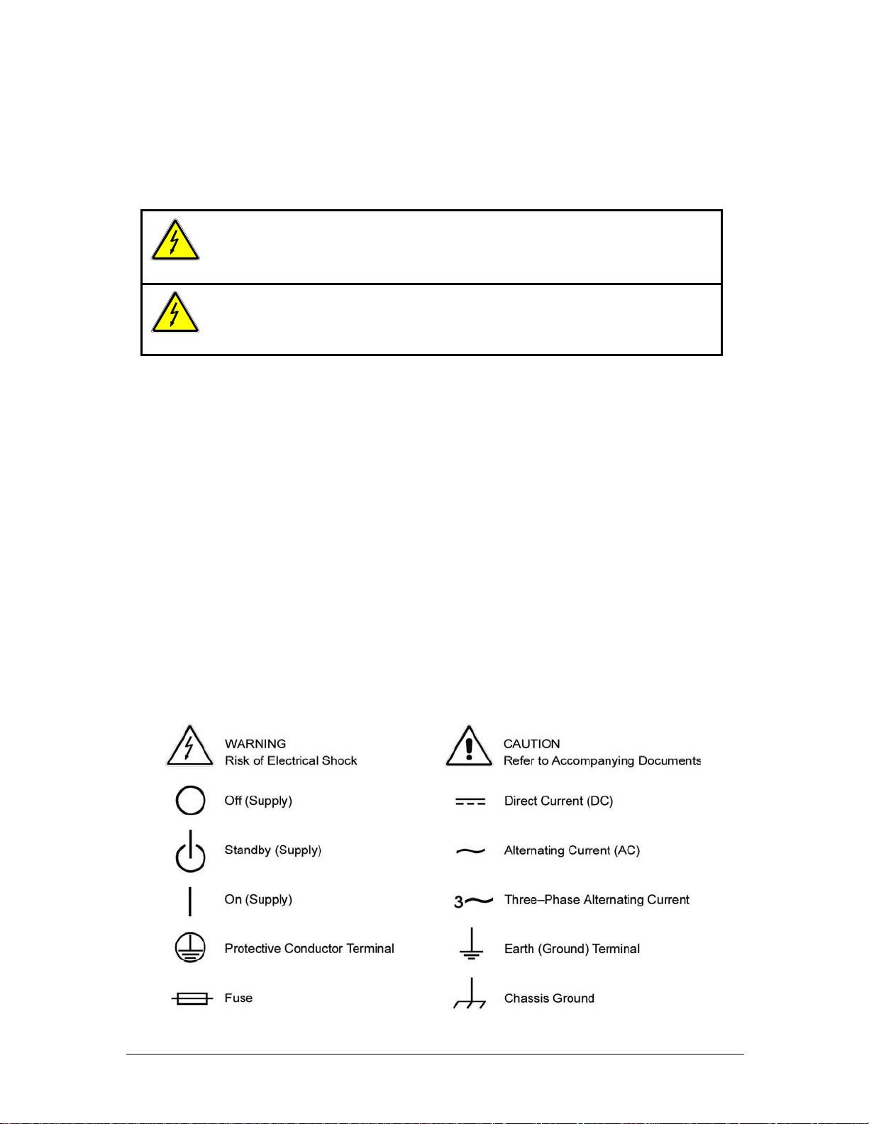
SAFETY SYMBOLS
iii
Page 8

This page intentionally left blank.
iv
Page 9

Product Family: HPD Series Programmable DC Power Supply
Warranty Period: Five Years
WARRANTY TERMS
AMETEK Programmable Power, Inc. (“AMETEK”), provides this written warranty covering the
Product stated above, and if the Buyer discovers and notifies AMETEK in writing of any defect in
material or workmanship within the applicable warranty period stated above, then AMETEK may,
at its option: repair or replace the Product; or issue a credit note for the defective Product; or
provide the Buyer with replacement parts for the Product.
The Buyer will, at its expense, return the defective Product or parts thereof to AMETEK in
accordance with the return procedure specified below. AMETEK will, at its expense, deliver the
repaired or replaced Product or parts to the Buyer. Any warranty of AMETEK will not apply if the
Buyer is in default under the Purchase Order Agreement or where the Product or any part
thereof:
is damaged by misuse, accident, negligence or failure to maintain the same as
specified or required by AMETEK;
is damaged by modifications, alterations or attachments thereto which are not
authorized by AMETEK;
is installed or operated contrary to the instructions of AMETEK;
is opened, modified or disassembled in any way without AMETEK’s consent; or
is used in combination with items, articles or materials not authorized by AMETEK.
The Buyer may not assert any claim that the Pr od ucts are not in conformity with any warranty
until the Buyer has made all payments to AMETEK provided for in the Purchase Order Agreement.
PRODUCT RETURN PROCEDURE
1. Request a Return Material Authorization (RMA) number from the repair facility (must be
done in the country in which it was purchased):
In the USA, contact the AMETEK Repair Department prior to the return of the
product to AMETEK for repair:
Telephone: 800-733-5427, ext. 2295 or ext. 2463 (toll free North America)
858-450-0085, ext. 2295 or ext. 2463 (direct)
Outside the United States, contact the nearest Authorized Service Center
(ASC). A full listing can be found either through y our local distribu tor or our
website, www.programmablepower.com, by clicking Support and going to the
Service Centers tab.
2. When requesting an RMA, have the following information ready:
Model number
Serial number
Description of the problem
NOTE: Unauthorized returns will not be accepted and will be returned at the shipper’s expense.
NOTE: A returned product found upon inspection by AMETEK, to be in specification is subject to
an evaluation fee and applicable freight charges.
v
Page 10

This page intentionally left blank.
vi
Page 11

Contents
Section 1.
Features and
Specifications
Section 2.
Installation
Section 3.
Connection
and Sensing
Section 4.
Operation
Load
Introduction ..................................................................................................................... 1
Features .......................................................................................................................... 1
Options and Accessories .............................................................................................. 2
Front Panel Controls ....................................................................................................... 2
Rear Panel Connectors and Outputs.............................................................................. 3
Electrical Specifications .................................................................................................. 4
Additional Electri cal Specifications ............................................................................... 5
Input Conditions ........................................................................................................... 5
Electrical Characteristics ................................................................................................. 6
Environmental Specifications .......................................................................................... 6
Mechanical Specifications .............................................................................................. 7
Chassis Dimensions and Weight .................................................................................... 8
Introduction ..................................................................................................................... 9
Basic Setup Procedure ................................................................................................ 9
Initial Inspection .............................................................................................................. 9
Periodic Cleaning ................................................................................................ 9
Rack Mounting .............................................................................................................. 10
Location and Ventilation ................................................................................................ 10
AC Input Power Connection ......................................................................................... 11
AC Input Cord .................................................................................................... 11
Functional Tests ......................................................................................................... 12
Power-on Check. ............................................................................................... 12
Voltage Mode Operation Check ......................................................................... 12
Current Mode Operation Check ......................................................................... 12
Introduction ................................................................................................................... 13
Load Connection ........................................................................................................... 13
Load Wiring .......................................................................................................... 14
Making Load Connections .................................................................................... 16
Connecting Multiple Loads ................................................................................ 16
Grounding ..................................................................................................................... 17
Local Sensing ............................................................................................................. 17
Output Jumpers for Local Sensing ..................................................................... 17
Remote Sensing ......................................................................................................... 19
Introduction ................................................................................................................... 21
Operating Modes ........................................................................................................ 21
Constant Voltage Mode Operation ....................................................................... 22
vii
Page 12

Contents
Constant Current Mode Operation ...................................................................... 22
Setting the Current Limit .................................................................................... 22
Setting the Supply to Operate in CI Mode ........................................................... 22
Automatic Mode Crossover ................................................................................. 23
Constant Power Loads ....................................................................................... 23
Using Multiple Supplies .................................................................................................24
Connecting Multiple Supplies in Series (Voltage Mode Only) ............................. 24
Connecting Multiple Supplies in Parallel ............................................................. 25
Split Supply Operation. ......................................................................................... 26
APPENDIX Rack Mount Installation Instructions……………………………………………………….A-1
viii Operating Manual for HPD Series Power Supply
Page 13

Section 1. Features and Specifications
Introduction
Section 1. Features and Specifications
Introduction
The HPD Series of DC power supplies provides highly stable, variable output
voltage and current for a broad range of development and syst em requirements.
These units employ high frequency switchi ng regulator technology to achieve high
power density and small package size, as well as a linear post-regulator circuit for
low output noise and fast response. A wide variety of options is available, including
both analog and IEEE-488 controlled progr amming, to make this series the first
Features
choice in flexible power system design.
Table 1.1
Model Output Voltage Output Current
15–20 0–15 V 0–20 A
30–10 0–30 V 0–10 A
60–5 0–60 V 0–5 A
300 Watt Series Models
• High frequency switching technology allows high power densit y, providing
increased power output in a small, light, package.
• The power supply delivers simultaneous digital displays for both voltage and
current, and bar graph displays for monitoring transient changes, which gives the
user the benefit of continuous, up-to-date information.
• Ten-tu rn vo ltage control permits high resolution setting of the output voltag e.
• Current limit is fully adjustable from zero to the rat ed output with a s ingle tu rn
control.
• The automatic crossover system allows the power supply to automat icall y
switch operating modes into current or voltage mode.
• Impedance-switched remote sensing lets operators display the voltage at the load
with no switch ambiguity.
• Multiple units can be connected in parallel or series to produce greater divers ity.
• Short-circuit-proof power outlets give greater op erating sa fe ty.
• These power supplies (available in single and dual outputs) can be co mbined
with one or more 60 watt series power supplies to create mixed units th at are
ideal for high precision applications.
1
Page 14

P
(For
A
(For
V
(
)
(For
(
(For
A
y
(
(
(
Section 1. Features and Specifications
Options and Accessories
Options and Accessories
• Internal Analog Programming (APG) interface for analog signal control of
voltage and current, overvoltage protecti on (OVP), master/slave output tracking,
and remote ON/O FF.
• Internal RS-232 interface for serial instrument programming using RS-232
protocol.
• Internal GPIB interface for complete remote digital programming. IEEE-488
standard.
• Optional 200–250 Va c input (Option AC200). Standard is 115 V ac . Optional AC
input cords for use in different countries.
• Ten-turn current potentiometer (Option M11). Rack mount kit (Option RM).
• Locking voltage and/or current adjust knobs (Option M13A).
Front Panel Controls
units with APG installed.
units with APG installed.)
units with APG installed.)
OVP Adjust Potentiometer (OVP ADJ)
units with APG installed.)
Figure 1.1 shows the control s, LEDs, and meters located on t he uni t ’s front panel.
OVP Shutdown (OVP)
P
M
S
D
O
V
OV
DJ
VOLTAGE CURRENT
MODE
Volts, Amperes)
nalog Bar Graph Displa
Current Limit Mode
Indicator (Red LED)
Current Limit Adjust Knob
1-turn standard)
Indicator (Green LED)
Voltage Mode
oltage Control Knob
10-turn standard)
Positive () Sense
Connection
Banana Jack)
POWER
SENSE
Return () Sense
Connection
Banana Jack)
AC Power Switch
Safety Ground
Binding Post (green or gray)
Positive () Output Binding Post (Red)
Return (
) Output Binding
Post(Black
Figure 1.1 Front Panel Controls
2 Operating Manual for HPD Series Power Supply
Page 15

)
j
)
)
Section 1. Features and Specifications
Rear Panel Connectors and Outputs
Figure 1.2 shows the programming interface indicators for units that have a digital
programming interface installed.
Remote ProgrammingLED(REM
OVP Shutdown(OVP
Figure 1.2 Remote Programming Interface Indicators
Rear Panel Connectors and Outputs
Figure 1.3 shows the connectors and outputs available at the rear panel. (Figure 1.3
shows the 15 V or 30 V low voltage model.)
Shutdown LED (SRQ)
OVPAd
ustPotentiometer (OVP ADJ
Figure 1.3 Rear Panel
Note
The power supply is shipped with jumpers for local sensing of the output voltage. See
“Local Sensing” on page 17.
3
Page 16

Section 1. Features and Specifications
Electrical Specifications
Electrical Specifications
Specifications are warranted over a temperature range of 0 to 30 °C with default
local sensing. Above 30 °C, the output voltage needs to be derated linearly to zero at
70 °C. Specif icat ions a re s ubjec t to cha nge without noti ce.
Tabl e 1.2 Electrical Specifications for 15 V to 60 V Models
Models 15–20
Output Ratings:
Output Voltage
Output Current
Output Power
Line Regulation:
Volta g e (0.01% of Vmax + 2 mV)
1
Current (0.01% of Imax + 2 mA)
2
Load Regulation:
Volta g e (0.01% of Vmax + 2 mV)
Current (0.01% of Imax + 2 mA)
Meter Accuracy:
Volta g e (1% of Vmax + 1 count)
Current (1% of Imax + 1 count)
Output Noise and Ripple :
3
Volt age (p-p)
Volt age (rms)
Current (rms)
Drift (60 minutes):
Voltage (0.02% of Vmax)
4
5
Current (0.03% of Imax)
6
Drift (8 hours):
Voltage (0.02% of Vmax)
Current (0.08% of Imax)
Temperature Coefficient
Voltage (0.015% of Vmax/°C)
Current (0.02% of Imax/°C)
1.
For input voltage variation over the AC input voltage range, with constant rated load.
2.
For 0 to 100% load variation, with constant nominal line voltage.
3.
Points of measurement are at the positive (+) and return (-) output terminal screws of the
output terminal block; RMS values are measured at bandwidth of 20fHz to 300kHz; PK-PK
values are measured at bandwidth of 20Hz to 20MHz.
4.
Current mode noise is measured from 10% to 100% of rated output voltage, full current.
5.
Maximum drift over 60 minutes with constant line, load, and temperat ure, after 60- minute
warm-up.
6.
Maximum drift over 8 hours with constant line, load, and temperat ure, after 60-m inute
warm-up.
7.
Change in output per °C change in ambient temperature, with constant line and load.
7
0–15 V
0–20 A
300 W
3.5 mV
4 mA
3.5 mV
4 mA
250 mV
300 mA
100 mV
5 mV
20 mA
3 mV
6 mA
3 mV
16 mA
2.25 mV
4 mA
4 Operating Manual for HPD Series Power Supply
30–10 60–5
0–30 V
0–10 A
300 W
5 mV
3 mA
5 mV
3 mA
400 mV
200 mA
100 mV
5 mV
10 mA
6 mV
3 mA
6 mV
8 mA
4.5 mV
2 mA
0–60 V
0–5 A
300 W
8 mV
2.5 mA
8 mV
2.5 mA
700 mV
60 mA
100 mV
5 mV
5 mA
12 mV
1.5 mA
12 mV
4 mA
9 mV
1 mA
Page 17

Additional Electrical Specifications
Voltage Mode Transient Response
(Time for the output voltage to
recover to ±50 mV band for 50%
load change in the range of 25% to
100% of the rated load.)
Time delay from power on until
output stable
Input Conditions
Rated AC Input Voltage 120 Vac standard; 230/240 Vac AC200 option
Maximum AC Input Power 625 VA
<500 s
1.5 s maximum
Section 1. Features and Specifications
Additional Electrical Specifications
Operational AC Input Voltage Range Single Unit: 104
Dual Unit: 104
AC 200 Option Single Unit: 200–250 V ac at 3 Arms
Dual Unit: 200–250 Va c at 6 Arms
Maximum Input Current (per unit) at 6 A maximum at 104 V ac
nominal power line impedances
Input Frequency Range 47–63 Hz
–127 Vac at 6 Arms
–127 Vac at 12 Arms
5
Page 18

Section 1. Features and Specifications
Electrical Characteristics
Electrical Characteristics
Switching Frequency 100 kHz (nominal)
Output Hold-up Time 25 ms at nominal line
Maximum Voltage Differential from
output to safety ground
Insulation Resistance
Isolation Voltage
(Output not to exceed ±400 Vdc from
chassis potential.)
Maximum Remote Sense Line Drop
Compensation. (Line drop must be
deducted from the supply’s maximum
output voltage.)
±400 Vdc
Input to chassis: >120
M
Output to chassis:
>120
M
Input to output: 1350 V ac
1.5 V/line
Environmental Specifications
Operating Ambient Temperature 0 to 30 °C with default local sensing. Above
Storage Tempe rature Range –55° to 85 °C
Humidity Range 0 to 80% RH non-condensing
Operating Altitude Up to 6,500 feet (2000 m)
Storage Altitude Up to 50,000 feet (15 000 m)
Installation Category Intended for use in installation category
Pollution Degree Category 2 (IEC 1010-1 standard )
6 Operating Manual for HPD Series Power Supply
30 °C, derate output linearly to 0 at 70 °C.
(overvoltage c ategory) II (IEC 1010-1 standard)
Page 19

Mechanical Specifications
Front Panel Voltage and Current
Control
Section 1. Features and Specifications
10-turn voltage and 1-turn current
potentiometers (10-turn current control
optional)
Mechanical Specifications
Front Panel Voltage Control
Resolution
0.02% of maximum voltage
Front Panel AC Input Power Switch Push ON/push OFF switch
Independent 3-digit green numeric LED
Front Panel Voltage and Current
Meters
display and analog bar graph displays for
current and voltage. F or meter accuracy, see
Table 1.2.
AC Input Connector Type IEC 320 Connector, appropriate power cord for
destination country.
Front Panel Output Connector Three binding posts: positive (+),
negative (–), and ground.
Rear Panel Output and Sense
Connector
Chassis Ground Front panel binding post and power cord safety
Cooling Convection cooled. Air enters the unit from the
Mounting Optional rack for mounting several units in a
Approvals
Four terminal barrier strips. The 60 V unit is
shipped with a 4-terminal output block.
ground.
bottom and lower sides and exits from the
upper sides and top.
standard rack. Can be combined with 60 watt
series units. See “Rack Mounting” on page 10.
CSA certified to UL 1012, and CSA C22.2 No.
107.1
FCC Part 15B and Industry Canada Class A
CE Marked for Low Voltage Directive and
EMC Directive (Class A emissions)
7
Page 20

Section 1. Features and Specifications
Chassis Dimensions and We igh t
Chassis Dimensions and Weight
8 Operating Manual for HPD Series Power Supply
Height
Width
Depth
Weight
5.25 in.
132 mm
4.25 in.
109 mm
11.7 in.
297 mm
7.7 lb.
3.5 kg
Page 21

Section 2. Installation
Introduction
This section provides recommendations and procedures for inspecting, installing,
and testing the power su pp ly.
Basic Setup Procedure
Initial Inspection
Tabl e 2.1 Basic Setup Procedure
Step# Description Action Reference
1
2
3
Inspection
Installation
Te st Perform functional tests for
Perform an initial physical
inspection of the suppl y.
Install the supply and
ensure adequate ventilation.
voltage mode operation,
current mode operation, and
front panel controls.
“Initial Inspection” on page 9
“Location and Ventilation” on
page 10
“Functional Tests” on page 12
Verify that the power supply was shipped with an IEC power cord set appropriate to
the destination country, two 2-position terminal block jumpers, and an operating
manual. When you first receive your unit, perform a quick physic al chec k.
1. Inspect the unit for scratches and cracks, broken switches, connectors, te rminals,
and missing accessories.
2. Have a service technician check the unit if you suspect internal damage.
If the unit is damaged, save all packing materials and not ify the carrier immedia tely.
Periodic
Cleaning
No routine servicing of the power supply is required except for periodic cleaning.
Whenever a unit is removed from operation, clean the outside surfaces with a weak
solution of soap and water. If required, use l ow-pressure compress ed air to blow dust
from in and around components on the printed circuit boards.
9
Page 22

Section 2. Installation
Rack Mounting
Rack Mounting
Use the power supply in benchtop or in rack-mounted applications.
WARNING
Ensure that any mounting screws do not protrude more than 1/8 in. (3.0 mm) into the
bottom of the unit.
The power is supply is designed to fill one quarter of a standard 19 in. (483 mm)
equipment rack.
Dual and quad configurations can be co mbin ed with 60 watt s eri es models for
custom applications. Con tact the manufacturer about the rack mount kit (Option
RM). For Rack Mount Installation Instructions, see Appendix A.
Location and Ventilatio n
Whether you place the power supply in a rack or on a bench, allow cooling air to
reach the ventilation inlets on the bottom and sides of the unit. Ensure that
rack-mounted supplies have 1 U (1.75 in./44.5 mm) above and below units. Any
ventilation space around the supply will further lower internal operating
temperatures.
See “Environmental Specifications” on page 6, for the operating altitude
specification and the operating ambient temperature range measured at the unit case.
10
Operating Manual for HPD Series Power Supply
Page 23

AC Input Power Connection
WARNING
There is a potential shock hazard if the power supply chassis and cover are not
connected to an electrical ground via the safety ground in the AC input connector.
Ensure that the power supply is connected to a grounded AC outlet with the
recommended AC input connector configured for the available line voltage as
described in this section.
CAUTION
!
When the power switch is turned on, the output voltage or current previously set is
The AC input connector is a standard IE C 320 male connector located on the power
supply’s rear panel.
applied to loads.
Section 2. Installation
AC Input Power Connection
Tabl e 2.2 Operational AC Input Voltage Ranges and Frequency
AC Voltag e Range Frequency
104–127 Vac 1(standard) 47–63 Hz
200–250 Vac 1(AC200 option) 47–63 Hz
AC Input
Cord
WARNING
The AC input cord is the disconnect device for the power supply. The plug must
be readily identifiable by and accessible to the operator. The input cord must b e
no longer than 9.85 feet (3 m).
The AC input cord that we provide is appropriate to the destination country. If you
require a special cord, call us.
11
Page 24

Section 2. Installation
Functional Tests
Functional Te sts
Power-on
Check
Voltage Mode
Operation
Check
These functional test procedures include power-on and front panel function checks
as well as voltage and current mode operation checks.
1. Ensure that the front panel power switc h is in the extended (OFF) position and
the voltage and current controls are in their fully counter-clockwise positions.
2. Ensure that the AC line voltage is within operating range.
3. Plug the line cord into a grounded AC outlet.
4. Push the power switch to turn on the power supply .
After a short power-on delay, the display and the red current mode LED lights. The
meter reading remains at zero.
For more about standard operations, see Section 4, “Operation”.
1. Ensure that the front panel voltage and current control are turned fully
counter-clockwise.
2. Set the power switch to ON.
3. Rotate the current control one half-turn clockwise. Slowly rotate the voltage
control clockwise and observe the digital met er. Minimum control range should
be from zero to maximum rated output. Observe the bar graph meter to see that
it tracks as the voltage rises. Verify that the voltage mode indicator light is ON.
4. Set the power switch to OFF.
Current Mode
Operation
Check
1. Ensure that the front panel power swit ch is s et to OFF.
2. Rotate the voltage and current controls fully counter-clockwise.
3. Rotate the voltage control one half-turn clockwise.
4. Connect a short circuit across the output terminals. Use leads of sufficient
current carrying capacity.
5. Set the power switch to ON.
6. Rotate the current control slowly clockwise. The control range should be fro m
zero to the maximum rated output. Also check that the current bar graph meter
follows the rise in current and that the current mode indicator light is ON.
7. Set the power switch to OFF.
12 Operating Manual for HPD Series Power Supply
Page 25

Section 3. Load Connection and Sensing
Introduction
Load Connection
This section covers single and multiple load connection, constant voltage and
constant current operating modes, and alternate power supply configurations such as
series and parall el connections.
WARNING
There is a potential shock hazard at the load when using a power supply with an
output greater than 40 V. Take appropriate precautions to protect personnel against
accidental contact with hazardous voltages. Also ensure that the insulation rating of
the load wiring and circuitry is greater than or equal to the maximum voltages to
ground being applied.
CAUTION
!
When making load connections, be sure to observe correct polarity or the power
supply may be damaged.
Yo u can obtain reliable performance from your power supply if you take certai n
basic precautions when making load con nectio ns.
To obtain a stable, low noise output, pay attenti on to the following:
1. consider the conductor ratings, the system grounding techniques and the way
that you make AC input, DC output, and remote sensing connections
2. use a conductor size that satisfies the current rating requirements
3. to overcome impedance and coupling effects, we recommend larger gauge wire
and shorter leads.
4. where positive load transient s suc h as back EMF (electromotive force) from a
motor may occur, connect a transorb or a varistor across the output to protect the
power supply.
13
Page 26

Section 3. Load Connection and Sensing
Load Connection
Load Wiring To select wiring for connecting the load to the power supply, consider the following
factors:
• Insulation rating of the wire
• Current carrying capacity of the wire
• Maximum load wiring length for operation with sense lines
• Noise and impedance effects of the load lines
Insulation Rating Use load wiring with a minimum insulation rating at least
equivalent to the maximum output voltage of the power supply. If the output is offset
from ground, the insulation must be rated at least for the sum of the supply’s
maximum output and the offset.
Current Carrying Capacity As a minimum, load wiring must have a current
capacity greater than the output current rating of the power supply. This ensures that
the wiring will not be damaged even if the load is shorte d. See T a b l e 3.1 for the
2
maximum current rating, based on 450 A/cm
, for various gauges of wire rated for
105 °C operation. Operating at the maximum current rating results in a temperatu re
rise of approximately 30 °C for a wire operating in free air. Where load wiring must
operate in areas with elevated ambient temperatures or is bundled with other wiring,
use larger gauges or wiring rated for higher temperatures.
Tabl e 3.1 Current Carrying Capacity for Load Wiring
Wire Size
(AWG)
20 2.5 6 61
18 4 4 97
16 6 2 155
14 10 1 192
12 16 1/0 247
10 21 2/0 303
8 36
Maximum Current
(A)
Wire Size
(AWG)
Maximum Current
(A)
14 Operating Manual for HPD Series Power Supply
Page 27

Section 3. Load Connection and Sensing
Load Connection
Load Wiring Length for Operation W ith Se nse Lines
remote sensing, you must limit the voltage drop across each load line. See Figure 3.1
for some maximum allowable lengths for a given load current and wire size. We
For applications using
recommend that you use the larger load wiring to ensure a smaller voltage drop
(0.1 V typical maximum), although units can compensate for up to 0.5 V dr op in
each line1.)
Figure 3.1 Maximum Wire Length for 100 mV Line Drop
Noise and Impedance Effects To minimize noise pickup or radiation, use
shielded pair w iring of the shortes t possible length for load wires. Connect the s hield
to the chassis via the front panel b inding post or a rear panel mounting sc rew. Where
shielding is impossible or impractical, simply twisting the wires together will offer
some noise immunity.
1. Any losses in the load cables must be deducted from the maximum output
voltage of the supply. For exa mple, a 15 V supply with a 1 V loss in the load
cables can supply a maximum of 14 V regulated at the load.
15
Page 28

Section 3. Load Connection and Sensing
Load Connection
Making Load
Connections
Connections at the Front Panel Binding Pos ts
To make connections at the front panel, connect load wires using s tri pped wire
(0.6 in./15 mm), spade lugs, or banana plugs to the output binding posts.
For binding posts locations, see Figure 1.1, “Front Panel Controls”.
Connections at the Rear Panel Terminals
Low Vol ta ge Models
appropriate gauge wire1 following the steps below:
To make load connections to low voltage m odels, attach an
1. Strip load wire s 0.75 i n. (19 mm ). An alte rn ati ve is to attach tongue lugs (#6
stud) to the load wires, following the manuf acturer ’s instru ctions.
2. Using a flat-bladed or #2 Phillips screwdriver, loosen the positive () and
negative () output terminal screws on the output barrier strip. See Figure 3.2,
“Output Barrier Strip With Jumpers Installe d”.
3. Wrap stri pped wi re around the appro priate term inal s cr ew . Tig hte n the sc r ew .
High Vol t ag e Models T o make load connections to high voltage models, attach
an appropriate gauge wire1 (maximum #12 wire) following the steps below :
1. Strip load wires 0.6 in. (15 mm).
2. Using a 1/8 in. (4 mm) flat-bladed screwdriver, loosen the terminal screws on the
output terminal block. Insert wires into the output terminals (, ) from the
bottom of the block. See Figure 3.3, “Output Termi nal Block Wit h Jumpers
Installed”.
3. Tighten the terminal screws.
Connecting
Multiple
Loads
Proper connection of distributed loads is an important aspect of power supply use. A
common mistake is to connect leads from the power supply to one load and then from
that load to other loads. In this parallel power dis tribution method, the vol tage at each
load depends on the current drawn by the other loads, and DC ground loops develop.
Except for low current applications, we recommend that you do not use this method.
1. See Table 3.1, “Current Carrying Capacity for Load Wiring,” on page 14 for the
16 Operating Manual for HPD Series Power Supply
correct wire gauge.
Page 29

Grounding
Local Sensing
Section 3. Load Connection and Sensing
Grounding
Make proper ground connections to avoid developing paths between separate ground
points. To avoid ground loops, there must be only one ground return point in a power
system. If the load itself is not grounded, ground the positive or negative output to
the supply’s chassis using a rear panel screw or the front panel ground binding post.
Output voltage can be sensed from both the rear panel and the front panel output
connectors. Default local sensing regulates the voltage at the power supply output
terminal. Use remote sensing (see “Remote Sensing” on page 19) when the voltage
needs to be regulated at the load rather than at the power supply output terminals.
Output
Jumpers for
Sensing
Local
Without sense line connections, the supply regulates the voltage at the output
terminals of the power suppl y. For improved local sensing, connect jumpers between
the sense terminals and the output terminals. See Figure 3.2 and Figure 3.3.
See Figure 1.1, “Front Panel Controls”, and Figure 1.3, “Rear Panel”, for sense
terminal locations on the front and rear pa nels.
WARNING
Disconnect the AC input before installing or removing jumpers.
Low Voltage Models T wo barrier strip jumpers are shipped unattached with 15 V
and 30 V models. If your application requires precisely regulated output voltage at
the rear output terminals, ins tall the jumpers as noted be l ow .
1. Use a flat-bladed or #2 Phillips screwdriver to loosen the four terminal screws at
the output barrier strip.
2. Slide the jumpers under the screws.
3. Tighten the screws to the barrier strip. See Figure 3.2.
17
Page 30

Section 3. Load Connection and Sensing
Local Sensing
Figure 3.2 Output Barrier Strip With Jumpers Installed
High Vol t ag e Models Two wire jumpers are shipped unattached with 60 V
models. If your application requires precisely regulated output volt age at the rear
output terminals, install the jumpers by inserting the jumper wires into the jumper
terminals as shown. See Figure 3.3.
Wire
Jumper
Figure 3.3 Output Termin al Block With Jumpers Instal led
18 Operating Manual for HPD Series Power Supply
Page 31

Remote Sensing
Section 3. Load Connection and Sensing
Remote Sensi ng
WARNING
There is a potential shock hazard at the sense points when using a power supply
with a rated output greater than 40 V. Ensure that connections at the load end are
shielded to prevent contact with hazardous voltages.
CAUTION
!
Operation of the supply in remote sense mode without the assured connection of
the load wires and remote sense wires to the load may damage the power
supply.
CAUTION
!
Ground the sense line shield in one place only. Locations include the power
supply’s return output connection at the load, the power supply’s return output at
the negative output terminal, or the power supply’s ground binding post on the
front panel.
Remote sensing permits you to relocate the regul ation point of the power supply
from the output terminals to the load or other distribution point ter min als.
The power supply provides sense connections beside the output terminals at the front
and rear panels. Use 22-24 AW G twisted, shielded pair wiring to make s ense
connections.
With the remote sense leads in place, the supply regulates for the displayed voltage
at the point where the sense lines are connected to the output leads (provided the sum
of these lead losses does not exceed 0.5 V). With the sense lines disconnected, the
supply regulates the voltage at the output termi nals. Rem ote sensing is not required
for constant current mode of operation, where the supply is regulating the output
current.
Note
Do not operate the supply with sense lines connected to the load without also connecting
the normal load power leads to the output terminals.
Always use shielded pair wiring for sense lines to minimize noise effects. (See
“Grounding” on page 17.)
CAUTION
!
Do not reverse positive (+) and negative () lead connections.
19
Page 32

Section 3. Load Connection and Sensing
Remote Sensing
20
Operating Manual for HPD Series Power Supply
Page 33

Section 4. Operation
Introduction
Operating Modes
Once you have installed the power supply and have connected both the AC input
power and the load as covered in Section 2, “Installation” , the power supply is ready
to operate.
• “Operating Modes”, below, offers a brief explanation of Constant V oltage and
Constant Current Mode operation.
• “Connecting Multiple Supplies in Series (Voltage Mode Only)” on page 36,
covers using multiple supplies.
Your power supply has two basic opera ting mode s: Const ant Voltage Mode and
Constant Current Mode. The mode in which the power supply operates at any given
time depends on the combination of:
• Output voltage setting V
• Output current limit setting I
• Resistance or impedance of the attached load R
SET
SET
L
Figure 4.1 represents the relationships between these variables.
Output
Voltage
V SET
Figure 4.1 Relationship Between Operating Mode Variables
O
O
Note
The control circuits have been designed to allow you to set output voltage and current
up to 5% over the model-rated maximum values. The power supply will operate within
these extended ranges, but we cannot guarantee full performance to specification.
Constant Voltage
Mode Region
Constant Current
Mode Region
I SET
R
V
L
>
Crossover Point
Output
Current
SET
I
SET
R
R
L
=
L
<
V
SET
I
SET
I
SET
SET
Where:
= Load Resistance
R
L
V
= Output Voltage Setting
SET
I
= Output Current Setting
SET
V
21
33
Page 34

Section 4. Operation
Operating Modes
Constant
Voltage Mode
Operation
The power supply will operate in constant voltage (CV) mode whenever the load
current IL is less than the current limit setting I
In CV, the power supply maintains the output vol tage at the selec ted v alue (V
or: IL < I
SET
(Note: IL = V
SET
SET
/ RL).
SET
while the load current IL varies with the load requirements.
)
Constant
Current Mode
Operation
Setting the
Current Limit
Setting the
Supply to
Operate in CI
Mode
To use the power supply in CV mode, either set the current limit to maximum by
turning the current control to its extreme clockwise position, or take the precaution
of setting a desired maximum current, and then set the voltage control to the desired
voltage.
The power supply will operate in constant current (CI) mode whenever the load
resistance is low enough that at V
current limit setting I
SET
.
the load current would be greater than the
SET
V
SET
-------------
I
R
SET
L
In CI mode, the power supply maintains the output current at the selected value (I
while the output voltage vari es with the load requirements.
Set the Current Limit by following the steps below:
1. Connect a shorting lead across the output terminals.
2. Turn the voltage control a half-turn clockwise.
3. Set the desired maximum current limit by turning the current control slow ly
clockwise to the desired level.
4. Disconnect the sh ortin g lead from the outpu t terminals. The power supply will
now automatically switch into current limiting mode (curr ent regulation) as
soon as the preset current level is reached.
To operate th e supply i n CI mode:
1. Set the current limit as described above.
2. Set the voltage control fully clockwise or to the c ompli ance volta ge of the
circuit.
SET
)
As soon as the supply starts operating in current mode, the red current mode
LED will turn on.
22
34
Operating Manual for HPD Series Power Supply
Page 35

Automatic
Mode
Crossover
Constant
Power Loads
Section 4. Operation
Operating Modes
The automatic cross over syst em allows the power supply to a utomati cally sw itch
operating modes in response to changing load requirements. For example, if the load
current attempts to increase above the setting of the current adjust control, the unit
switches automatically from CV to CI mode. If you lower the load requirements, the
supply automatically returns to CV mode.
When powering constant pow er loads such as switch mode regulators, it is preferable
to run in constant voltage mode, with the current limit set to supply ample current.
Operating near the CV/CI transition point can cause operation to become unstable.
23
35
Page 36

Section 4. Operation
Using Multiple Supplies
Using Multiple Supplies
Connecting
Supplies in
Mode Only)
Multiple
Series
(Voltage
Yo u can operate two or more power su pplie s with out puts connected in ser ies or in
parallel to obtain increased load voltage or current. A split supply configuration
allows you to obtain two positive outputs or a positive and a negative output.
!
As described be l o w , you can connect pow er supplie s in series to obtain a single
output supply with higher output voltage. Connect the negative (–) terminal of one
supply to the positive (+) terminal of the next s upply.
CAUTION
The maximum allowable voltage in series operation is 400 Vdc.
The total voltage available is the sum of the maximum voltages of each supply (add
voltmeter readings). The maximum current availa ble to the load is equal to the
current of the lowest rated supply in the series. See Figure 4.2 for a representation of
series operation.
Figure 4.2 Series Operation With and Without OVP
Note
Yo u do not need to use remote sensing for series operation. If you choose to use it,
refer to “Remote Sensing” on page 19 and connect as shown in Figure 4.2.
Diodes CR1 and CR2 protect sense circuits during transient ev ents such as
momentary current limit events which may cause supply outputs to collapse . Use
general purpose 1A rectifiers, such as IN1004 or equivalent.
24
36
Operating Manual for HPD Series Power Supply
Page 37

Connecting
Multiple
Supplies in
Parallel
Section 4. Operation
Using Multiple Supplies
CAUTION
!
For parallel operation with OVP-equipped supplies, set all OVP trip points higher
than the maximum output voltage. T o prevent the internal OVP fuse from blowing
during OVP trip events, add external blocking diodes as illustrated in Figure 4.3.
Use diodes rated to handle the maximum current for the su pp ly .
CAUTION
!
The configuration shown in Figure 4.3 is for use with local sense onl y . Do not
attempt to use remote sens ing with the di odes as shown. Damage to the sense
circuits may occur.
As described belo w , you can connect power supplies in parallel to obtain a single
output supply with a higher output current limit. Set all the outputs to the same
voltage before connecting the positive (+) and negative () term inals in parallel.
The total current available is the sum of the maximum currents of each su pp ly. The
maximum voltage available at the load is equal to the voltage of the lowest rated
suppl y. When you connect two supplies in parallel, the supply with the higher
voltage setting is in the current limiting mode , while the other supply controls t he
output voltage.
Figure 4.3 Parallel Operation With OVP-Equipped Units (local sensing only)
37
25
Page 38

g
y
Section 4. Operation
Using Multiple Supplies
Split Supply
Operation
Split supply operation uses two power supplies to obtain two positive voltages with
a common ground, or to obtain a positive-negative sup pl y.
Two Positive Vo l ta ge s To obtain two positive voltages, join the negat ive output
terminals of both supplies in a common connection as show n in Figure 4.4. The
positive output terminals provi de the required volta ges with respect to the common
connection.
Postive Sense
Positive Output
Terminal
Negative Output
Terminal
Return Sense
Power Supply 1
Postive Sense
Positive Output
Terminal
Negative Output
Terminal
Return Sense
Power Suppl
2
Load Lines
Use the largest gauge and
shortest len
th possible
Positive Load
Terminal #1
Postive Load
Terminal #2
Negative Load
Terminal
Load
Figure 4.4 Split Supply Operation of Multiple Supplies (two positive voltages)
Positive-Negative Supply T o obtain a positive-negative supply, connect the
negative output terminal of one supply to the positive terminal of the second supply
as shown in Figure 4.5. The positive output terminal of the first supply now provides
a positive voltage relative to the common connection. The negative output terminal
of the second supply provides the negative voltage. The current limits can be set
independently of each other. The maximum current available in split operation is
equal to the rated output of the supplies.
26
38
Operating Manual for HPD Series Power Supply
Page 39

y
Section 4. Operation
Using Multiple Supplies
PostiveSense
Positive Output
Terminal
Negative Output
Terminal
Return Sense
Power Supply 1
Postive Sense
Positive Output
Terminal
Negative Output
Terminal
Return Sense
Power Suppl
Figure 4.5 Split Supply Operation of Multiple Supplies (positive-negative supply)
2
Load Lines
Use the largest gauge and
shortest length possible
Positive Load
Terminal
Common Load
Terminal
Negative Load
Terminal
Load
Note
The optional Analog Programming (APG) Interface has a Master/Slave Tracking
feature which will allow one-knob control of both supplies in a split supply configuration.
27
39
Page 40

APPENDIX
28
RACKMOUNTINSTALLATIONINSTRUCTIONS
Page 41

4X 9
ITEMS 10 AND 13 NOT
USED FOR HPD
29
40
 Loading...