

Page 1

INSTALLATION MANUAL
L
INEAR
D
ISPLACEMENT
T
RANSDUCERS
955D BRIK
GEN III WITH DIGITAL OUTPUT
955 Series
Series 956
ABSOLUTE PROCESS CONTROL
KNOW WHERE YOU ARE... REGARDLESS
Includes 955D
Programming & Maintenance
Instructions Plus Accessory Guide
Page 2

Preface
This manual is divided into three chapters. Chapter 1
provides the hardware overview for the 955D Linear
Displacement Transducers (LDT). Chapter 2 provides
instructions for installing the LDT to a mounting bracket.
Chapter 3 provides an overview and wiring instructions.
To further assist you, a glossary is provided at the back of
the manual.
!
CAUTION
Disconnect Power Before Servicing. The
Gemco 955D LDT Contains No Serviceable
Components. Consult Factory for Repair or
Replacement.
AMETEK Automation & Process Technologies has
checked the accuracy of this manual at the time it was
approved for printing. However, this manual may not
provide all possible ways of installing and maintaining
the LDT. Any errors found in this manual or additional
possibilities to the installation and maintenance of
the LDT will be added in subsequent editions. Any
comments you may have for the improvement of this
manual are welcomed.
U
Table of Contents
Chapter 1 Hardware Overview .........................3
Chapter 2 Installing the LDT ............................ 3
2.1 Mounting Instructions .............................3
2.2 Mounting the Magnet Assembly ............. 3
Chapter 3 955D Outputs ...................................5
3.1 CP (Control Pulse) .................................5
3.2 VP (Variable Pulse) ................................5
3.3 RS (Start/Stop) ....................................... 6
3.4 955D Wiring Connections ......................6
3.5 Features ........................ ........................7
3.6 Troubleshooting for 955D .......................8
3.7 Catalog Numbering System ...................9
3.8 Specifi cations for 955D .......................... 10
3.9 Accessories ............................................ 10
955D Glossary ...................................................11
AMETEK reserves the right to revise and redistribute
the entire contents or selected pages of this manual.
All rights to the contents of this manual are reserved
by AMETEK. The BRIK is a registered trademark of
AMETEK.
2
1080 N. Crooks Road • Clawson, MI 48017 • 800.635.0289 • 248.435.0700 • Fax 248.435.8120 • www.AMETEKAPT.com
Page 3
Chapter 1 Hardware Overview
Chapter 2 Installing the LDT
Overview
The Series 955D BRIK with Digital Output is an
accurate, auto-tuning, non-contact, Linear Displacement
Transducer in an economical, low profi le package. The
transducer utilizes our fi eld proven magnetostrictive
technology to give absolute position, repeatable to .006%
of the sensing distance. The streamlined anodized
aluminum extrusion houses the sensing element and
electronics. The magnet moves over the sensing
element that determines the position and converts it to a
digital output.
Features
The 955D has a truly unique feature. This LDT has autotuning capability, the ability to sense a magnet other than
the standard slide magnet and adjust its signal strength
accordingly.
There is an indicator LED that is located at the connector
end of the probe and provides visual status information
regarding the operation of the probe. Green indicates
proper or normal operation. Red indicates the loss of the
magnetic signal or a probe failure. The LED turns Yellow
if no interrogation signal detected. When the probe is
in the normal mode of operation, the LED with remain
illuminated continuously.
LED Colors
Green Magnet is present and within the active range.
Red Fault, the LDT has lost its signal from the magnet or the
magnet has moved into the Null Zone or Dead Band.
Yellow No external interrogation pulse detected.
Note: The series number on your LDT is a record of all
the specifi c characteristics that make up your unit. This
includes what interface type it is, its output signal and
range, the type of connector the unit uses, and stroke
length. For a translation of the model number, see
Section 3.7 Catalog Numbering System.
The 955D BRIK with Digital Output is a Linear
Displacement Transducer. It provides a Control Pulse,
Start/Stop or Variable Pulse output signal that is
proportional to the position of the slide magnet assembly
along the length of the probe.
2.1 Mounting Instructions
The Series 955D can be mounted vertically or
horizontally using SD0522000 mounting brackets. The
mounting brackets slide in the grooves on the lower part
of the extrusion and clamp down when tightened. It is
recommended to use one mounting bracket on each end
and every three feet in between.
Ferro-magnetic material, (material readily magnetized)
should be placed no closer than .25” from the sensing
surface of the LDT.
2.2 Mounting the Magnet Assembly
Before mounting the magnet assembly, you should
consider the following
• Ferromagnetic material should not be placed closer
than 0.25” from the LDT’s sensing surface. Failure
to do so could cause erratic operation. Non-ferrous
materials, such as brass, copper, aluminum,
nonmagnetic stainless steel or plastics, can be
in direct contact with the magnet assembly and
sensing surface without producing any adverse
results.
• Make sure that the magnet is located within
the LDT’s active stroke area. Captive magnet
assemblies should be positioned so that they can
move freely over the entire area of the active stroke
without binding or pushing on the extrusion. Noncaptive magnet assemblies should be situated so
that the magnet is no further than 3/8” from the
sensing surface at any point in the fl oating magnet
assembly’s movement.
• When using the Floating Magnet assembly
(SD0522100), the magnet should be installed within
3/8” of the sensing surface. The magnet assembly
should also be installed in such a manner that
it remains an even distance from the aluminum
extrusion throughout the entire stroke. Improperly
installed magnets can result in output signal non-
linearity.
1080 N. Crooks Road • Clawson, MI 48017 • 800.635.0289 • 248.435.0700 • Fax 248.435.8120 • www.AMETEKAPT.com
3
Page 4
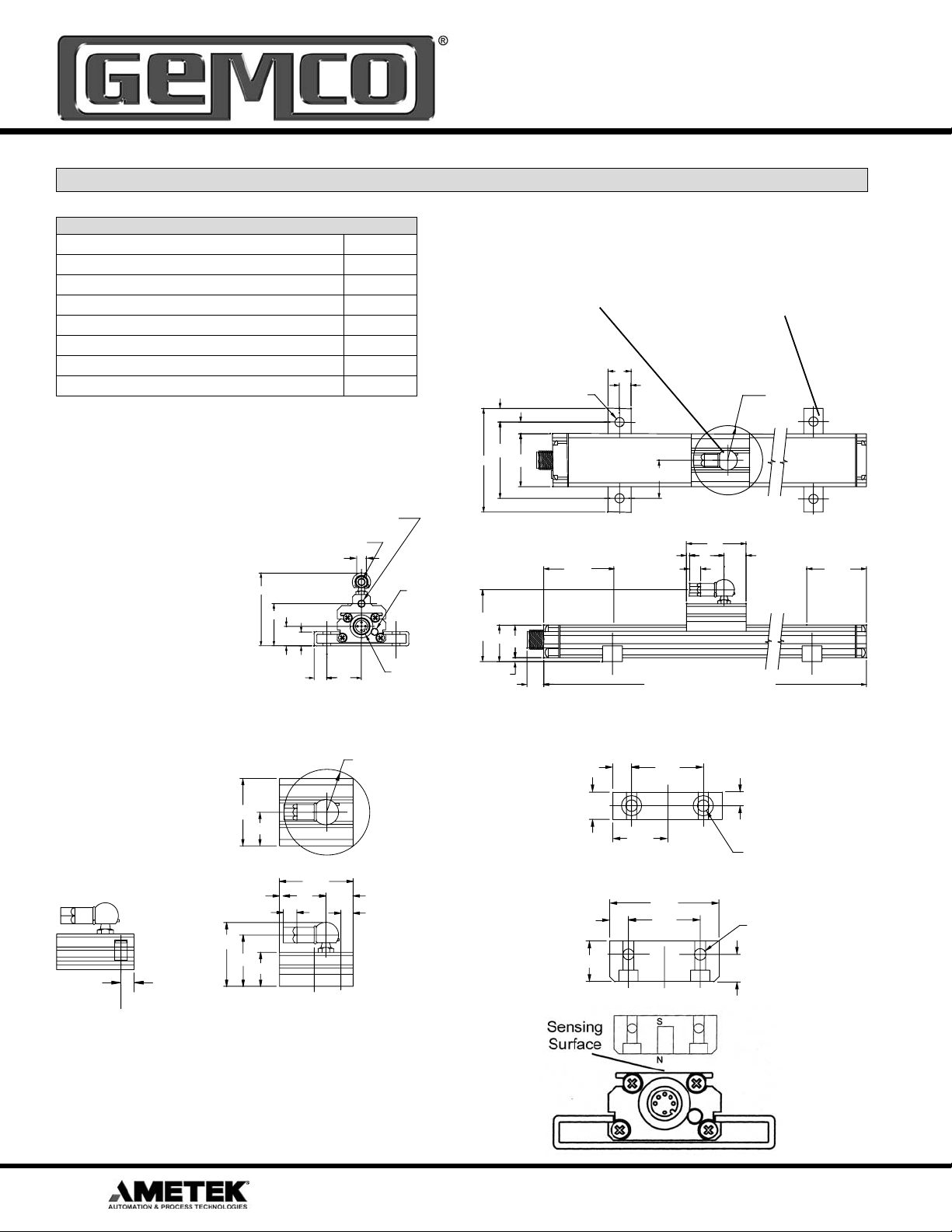
Dimension Drawing
Accessories
Item Part Number
Slide Magnet SD0521800
Float Magnet SD0522100
Mounting Foot SD0522000
6 Ft. Cable (6 Pin, Straight Micro Connector, Option E) 949021L6
12 Ft. Cable (6 Pin, Straight Micro Connector, Option E) 949021L12
6 Ft. Cable (6 Pin, Right Angle Micro Connector, Option E) 949022L6
12 Ft. Cable (6 Pin, Right Angle Straight Micro Connector, Option E) 949022L12
M5 X .56 DEEP
ALTERNATE MTG.
HOLE FOR LINKAGE
M5 X .40 DEEP
LINKAGE MTG. HOLE
.28
2.06
1.19
.55
.40
Mounting Brackets (SD0522000)
A standard female swivel
mounting arm is provided
with the slide magnet
assembly. For extensions
and other options contact
AMETEK at 800-635-0289.
slide in the grooves on the side
of the extruded housing. When
tightened down with fastening
hardware the mounting bracket
clamps the unit into place. It is
recommended to use one mounting
bracket on each end and every
three feet between.
.60
.22 MTG. HOLES
2 PER MTG. FOOT
.36
.30
1.97
2.68
1.37
NULL
LED
1.80
.92
.82
.30
1.00
1.50
.08
.87
.28
.56
R.89
360 ROTATION
DEAD
DEAD
BAND
ZONE
SLIDE MAGNET ASSEMBLY
P/N SD0521800
.25
OF MAGNET SLUG
1.30
1.37
1.04
.36 .98
.68
.08
.28
.69
1.50
.87
.56
6 Pin,12 mm EURO
MALE CONNECTOR
R.87
360 ROTATION
.25 TO CENTERLINE
OF MAGNET SENSOR
.10
.42
FLOATING MAGNET ASSEMBLY
P/N SD0522100
.50
TO CENTERLINE
.75
.34
1.00
OF MAGNET
.34
L = NULL +
1.31
2.00
1.31
STROKE + DEAD ZONE
DEAD BAND
.25
.20 THRU
.359 C’BORE
.21 DEEP
OTHER END
2 PLACES
.20 THRU
2 PLACES
.50
Note: The North Pole of the magnet
should be pointed towards the probe.
4
1080 N. Crooks Road • Clawson, MI 48017 • 800.635.0289 • 248.435.0700 • Fax 248.435.8120 • www.AMETEKAPT.com
Page 5
Chapter 3 955D Outputs
3.1 CP (Control Pulse)
The Control Pulse signal interface of the BRIK digital
output series is a differential RS-422 output. The maximum cable length for the differential digital LDT’s is 1,500
feet. To initiate a start pulse, an external device is used.
This start pulse should be 1.0 microsecond in duration.
After the start pulse is received, the LDT will generate
a stop pulse of 1.0 microsecond in duration. The time
between the leading edge of the start pulse to the leading edge of the stop pulse is proportional to the distance
from the Null Zone to the Magnet. The order of these two
pulses is illustrated in the Figure 3-1. To wire the 955DCP, see Figure 3-6. For proper grounding information,
see Section 3.4.
3.2 VP (Variable Pulse)
The Variable Pulse signal interface of the BRIK digital
output series is a pulse width modulated signal (RS-422).
The maximum cable length for the differential LDT’s is
1,500 feet. This LDT can also be confi gured for external
or internal interrogation. External interrogation is when
an external device connected to the LDT generates a
start pulse. This start pulse should be a minimum of 1.0
microsecond in duration. Within 50 nanoseconds after
the leading edge of the start pulse has been received,
the LDT will generate an output pulse. The duration of
the output pulse is proportional to the distance from
the Null Zone to the Magnet . The order of these two
pulses is illustrated in Figure 3-2. The 955D-VP can also
generate internal interrogations. This LDT will continually
output pulse width modulated signals. As with a 955DVP using an external interrogation, the duration of this
output pulse is proportional to the distance from the Null
Zone to the Magnet. This is illustrated in Figure 3-3. To
wire the 955D-VP, see Figure 3-6. For proper grounding
information, see Section 3.4.
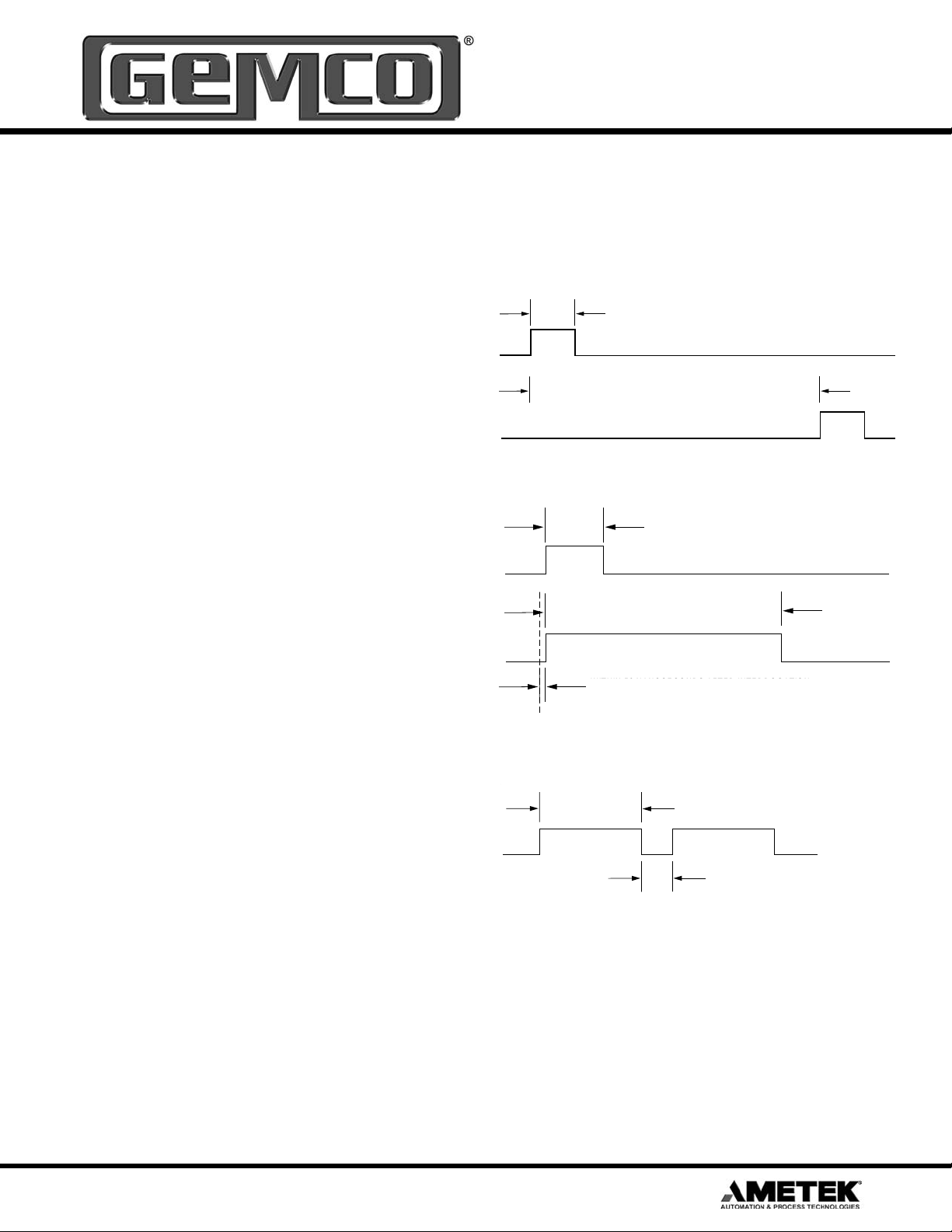
Figure 3-1 955D-CP
1 MICROSECOND (RECOMMENDED)
0.2 MICROSECONDS (MINIMUM)
+ INPUT (START PULSE)
TIME BETWEEN PULSES IS PROPORTIONAL TO
TIME BETWEEN PULSES IS PROPORTIONAL TO
DISTANCE BETWEEN MAGNET AND NULL ZONE
DISTANCE BETWEEN MAGNET AND HEX HEAD
+ OUTPUT (STOP PULSE)
Figure 3-2 955D-VP with External Interrogation
1 MICROSECOND (RECOMMENDED)
0.2 MICROSECONDS (MINIMUM)
INPUT (INTERROGATION)
WIDTH OF PULSE IS PROPORTIONAL TO
WIDTH OF PULSE IS PROPORTIONAL TO
DISTANCE BETWEEN MAGNET AND NULL ZONE
DISTANCE BETWEEN MAGNET AND HEX HEAD
OUTPUT PULSE
WITHIN 50 NANOSECONDS AFTER INTERROGATION
WITHIN 50 NANOSECONDS AFTER INTERROGATION
PULSE WIDTH MODULATED OUTPUT SIGNAL BEGINS
TO DISTANCE BETWEEN MAGNET AND HEX HEAD
Figure 3-3 955D-VP with Internal Interrogation
WIDTH OF PULSE IS PROPORTIONAL TO
WIDTH OF PULSE IS PROPORTIONAL
DISTANCE BETWEEN MAGNET AND NULL ZONE
TO DISTANCE BETWEEN MAGNET AND HEX HEAD
OUTPUT PULSE
LOW OUTPUT VARIES DEPENDING ON THE
LOW OUTPUT VARIES DEPENDING ON LENGTH
INTERROGATION TIME AND THE POSITION
PROGRAMMED VIA DIP SW2 SWITCHES 1-6
OF THE MAGNET
Recirculations
The method used to improve the resolution of a system
using a digital LDT. The “on” Time of a pulse width
output is multiplied by a specifi c factor (from 1-127).
This multiplication provides more counting time for the
counter in the customer’s electronics, thus improving
the resolution. The only disadvantage to the higher
recirculation numbers is the time needed to process the
signal.
1080 N. Crooks Road • Clawson, MI 48017 • 800.635.0289 • 248.435.0700 • Fax 248.435.8120 • www.AMETEKAPT.com
5
Page 6
3.3 RS (Start/Stop)
The Start/Stop signal interface of the BRIK digital output
series is differential RS-422 output. The maximum cable
length for differential LDT's is 1,500 feet. To initiate a start
pulse, an external device is used. This start pulse should
be a minimum of 1.0 microsecond in duration. Within 50
nanoseconds after the leading edge of the start pulse,
the LDT will generate a start pulse of 1.0 microsecond in
duration. A stop pulse of 1.0 microsecond in duration will
follow. The time it takes from the leading edge of the start
pulse to the leading edge of the stop pulse is proportional
to the distance from the Null Zone to the Magnet . The
order of these two pulses is illustrated in Figure 3-4. To
wire the 955D-RS, see Figure 3-6. For proper grounding
information, see Section 3.4.
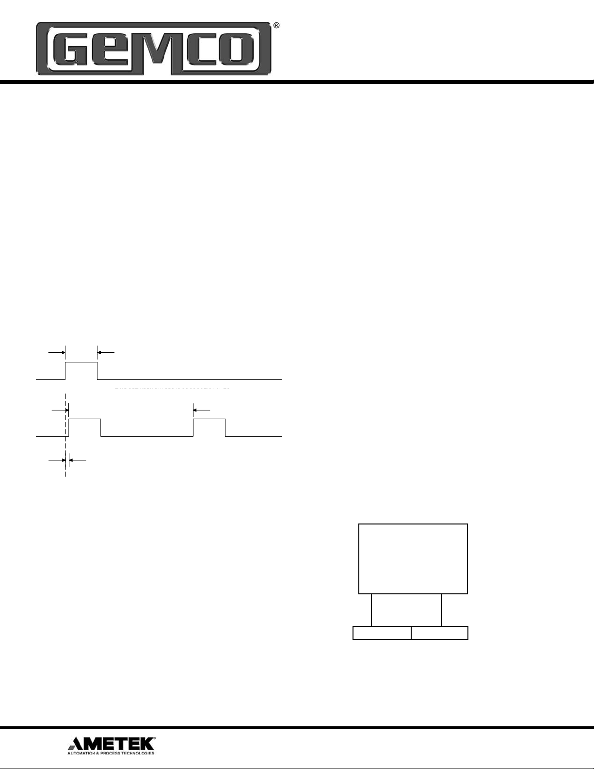
Figure 3-4 955D-RS
1 MICROSECOND (RECOMMENDED)
0.2 MICROSECONDS (MINIMUM)
INPUT (INTERROGATION PULSE)
OUTPUT (START PULSE) OUTPUT (STOP PULSE)
TIME BETWEEN PULSES IS PROPORTIONAL TO
TIME BETWEEN PULSES IS PROPORTIONAL TO
DISTANCE BETWEEN MAGNET AND NULL ZONE
DISTANCE BETWEEN MAGNET AND HEX HEAD
WITHIN 50 NANOSECONDS AFTER INTERROGATION
PULSE, START PULSE BEGINS
braid of tinned copper shield. Cable O.D. is .270. To
reduce electrical noise, the shield must be properly used.
Connect the cable’s shield to the controller system GND.
The connector shell on the probe is electrically connected
to the probe housing.
Always observe proper grounding techniques such as
single point grounding and isolating high voltage (i.e.
120/240 VAC) from low voltage (13.5-30 VDC cables).
Whenever possible, this cable should be run in conduit
by itself. The power supply common, the cable shield and
a good earth ground should be connected together at the
location of the power supply common.
!
WARNING
U
Do not route the BRIK output cable near high voltage
sources.
In order for the 955D to operate properly, the LDT’s
external power supply must provide a voltage between
+13.5 to +30 VDC. The power supply must be rated at
150mA minimum. The power supply should provide less
than 1% rippel and 10% regulations. (The power supply
should be dedicated to the LDT to prevent noise from
external loads from affecting the BRIK.)
3.4 955D Wiring Connections
Once the LDT has been installed, wiring connections can
be made. There are two groups of connections you will
need to make. They are as follows:
• Power Supply Connections (including ground and
shield)
• LDT Input/Output Connections
Power Supply/Ground Connections
The 955D standard cable is a 6 Pin, 12mm, Euro Style
cordset. It has 6 conductors of 24ga, with an aluminum/
polyester/aluminum foil with drain wire plus an overall
6
1080 N. Crooks Road • Clawson, MI 48017 • 800.635.0289 • 248.435.0700 • Fax 248.435.8120 • www.AMETEKAPT.com
Figure 3.5 Power Supply Wiring
UNIPOLAR
Single ended
power supply
+13.5 to +30 VDC
+ COM
Pin 1 (brown) Pin 3 (blue)
Page 7

Figure 3.6 Wiring Diagram
Cable Assembly
Part Number 949-021LX
(X = Length in Feet)
PIN - 1 BROWN
PIN - 2 WHITE
PIN - 3 BLUE
PIN - 4 BLACK
PIN - 5 GRAY
PIN - 6 PINK
POWER +
OUT +
COMMON
OUT-
INT-
INT+
949-021LX (X = Length in Feet)
Part Number
Shield
3.5 Features
Automatic Gain Control
The Automatic Gain Control feature will automatically
search and fi nd the magnet on power up, if power is
applied without a magnet on the LDT, the LED will turn
RED indicating no magnet signal is detected. Turn power
off and place magnet within the active stroke area. Reapply power.
When using the Floating Magnet assembly (SD0522100),
the magnet should be installed within 3/8” of the sensing
surface. The magnet assembly should also be installed
so that it remains an even distance from the aluminum
extrusion throughout the entire stroke. Improperly
installed magnets can result in output signal non-linearity.
LED Colors
Green Magnet is present and within the active programmed
Red Fault, the LDT has lost its signal from the magnet or the
Yellow No external interrogation signal detected.
range.
magnet has moved into the Null Zone or Dead Band.
1080 N. Crooks Road • Clawson, MI 48017 • 800.635.0289 • 248.435.0700 • Fax 248.435.8120 • www.AMETEKAPT.com
7
Page 8

3.6 Troubleshooting for 955D
Troubleshooting describes common problems that
may occur when installing the LDT and offers possible
solutions to these problems. If, after reading this
appendix, you are unable to resolve a problem, contact
our technical support department at 1-800-635-0289.
General Checks
Make sure that the magnet is located within the LDT’s
active stroke area. Captive magnet assemblies should
be positioned so that they can move freely over the entire
area of the active stroke without binding or pushing on
the extrusion. Non-captive magnet assemblies should be
situated so that the magnet is no further than 3/8” from
the sensing surface at any point in the fl oating magnet
assembly’s movement.
Note: Ferromagnetic material (material readily
magnetized) should be located no closer than 0.25” from
the sensing surface of the LDT. This includes mounting
brackets, magnet spacers, magnet brackets, and
mounting screws. Ferromagnetic material can distort the
magnetic fi eld, causing adverse operation or failure of the
LDT.
Check all LDT wires for continuity and/or shorts. It
is preferable that the cable between the LDT and the
interface device be one continuous run. If you are using
a junction box, it is highly recommended that the splice
junction box be free of AC and/or DC transient-producing
lines. The shield should be carried through the splice
and terminated at the interface device end.
Power Supply Check
the LDT wattage by the input voltage. For example, 2.5
watts divided by 24 VDC equals 105mA.
If your LDT is not operating properly, the LDT’s cable
may have an open or short, or the power supply is not
supplying suffi cient power. To verify this, perform the
following steps:
1. Turn the power supply off.
2. Remove the mating connector from the LDT.
3. Turn the power supply on.
4. Using a digital voltmeter, check pins 3 (GND) and
1 (+) from the mating end of the cable for a level
between +13.5 and +30 VDC.
If reading is between 13.5 and 30 VDC, turn power
supply off and go to step 7. If reading is below 13.5 VDC,
either your power supply is not providing enough power
or the LDT’s cable possibly has a short/open. Readings
of no voltage or minimal voltage (less than 5 volts) may
be due to short/open in the cable. If reading is NOT
between 13.5 and 30 VDC, go to step 5. If reading is
above 30 VDC, adjust power supply or replace.
5. Turn the power supply off.
6. Check the continuity of the individual wires of the
cable between the power supply and the LDT. Check
for continuity from one end of the cable to the other.
Also verify that no shorts exist between pins.
7. Reconnect the mating connector to the LDT.
8. Turn power supply on.
9. Using a digital voltmeter, check the power supply’s “+”
and “-” terminals for a voltage between
13.5 and 30 VDC.
This section will help you to determine if your power
supply is adequate for the LDT to operate properly, or if
the LDT’s cable has a short or open.
In order for the 955D to operate properly, the external
power supply must provide a level between 13.5 to
30 VDC. A power supply providing voltage above this
specifi ed range may damage the LDT. A power supply
providing power below this specifi ed range will not be
suffi cient to power the LDT. When powering more than
one BRIK on a single power supply, remember that each
BRIK requires 2.5 watts of power maximum. The amount
of current draw will vary based on the input voltage used.
To calculate the current draw for a particular LDT, divide
8
1080 N. Crooks Road • Clawson, MI 48017 • 800.635.0289 • 248.435.0700 • Fax 248.435.8120 • www.AMETEKAPT.com
Low voltage readings may indicate a power supply with
a wattage (current) rating that is too low. (Each LDT
requires 2.5 watts). If the cabling checks out in step 6
and your voltage is below 13.5 VDC, check your power
supply current rating. If voltage is between 13.5 to 30
VDC and the LDT is still inoperative, contact factory.
Page 9

3.7 Catalog Numbering System
Variable Pulse
955D 0120 EVP 001 X
955D BRIK with
Variable Pulse Output
Output Mode
VP = Variable Pulse
Stroke Length
Insert stroke length to 0.1 inch. Enter as
a four-place number. Example A 12.0”
stroke enters as 0120. To convert a metric
stroke in millimeters, multiply millimeter
Options
X = None
E = Wet environment.
Electronics sealed to IP68 Rating.
value by 0.03937 to arrive at inch value.
Interrogation Mode
I = Internal Interrogation
E = External Interrogation
Number of Recirculations
001 (Standard) to 127
Control Pulse or Stop/Start Pulse
955D 0120XX X
955D BRIK with
Control Pulse or
Stop/Start Output
Stroke Length
Insert stroke length to 0.1 inch. Enter as
a four-place number. Example A 12.0”
stroke enters as 0120. To convert a metric
Options
X = None
E = Wet environment.
Electronics sealed to IP68 Rating.
stroke in millimeters, multiply millimeter
Output Mode
value by 0.03937 to arrive at inch value.
CP = Control Pulse
RS = RS-422 Start/Stop Pulse
Note: Contact our Technical Support at 1-800-635-0289 for custom confi gurations.
3.8 Specifi cations for 955D
General Specifi cations
Null Zone
Dead Band
Extrusion Assembly
Connector
Sensor Length
Agency Approval
Shock & Vibration
Random Vibration
Shock
1080 N. Crooks Road • Clawson, MI 48017 • 800.635.0289 • 248.435.0700 • Fax 248.435.8120 • www.AMETEKAPT.com
3.00”
2.00”
Anodized Aluminum with gasket seals,
IP 67, IP 68 Optional
6 Pin, 12mm Euro Style Connector
5” to 180”
CE
MIL-STD 810E, 10Grms random,
20Hz - 2K Hz
Tested to 40G
Input Voltage
Current Draw
Nonlinearity
Repeatability
Hysteresis
Operating Temperature
Storage Temperature
Update Time
Electrical Specifi cations
Specifi cations are subject to change
and are based on a typical 36” LDT.
Unipolar 13.5 to 30 VDC
2.5 watts maximum
+/- 0.05% of full stroke
+/- 0.006% of full stroke
+/- 0.02% of full stroke
-20° to 70° C
-40° to 85° C
Controller Dependent
9
Page 10

3.9 Accessories
Slide Magnet Assembly
Part Number SD0521800
1.37
.68
.25
OF MAGNET SLUG
.08
.28
1.30
1.04
.69
Mounting Foot
Part Number SD0522000
0.2
(4 Holes)
Floating Magnet Assembly
Part Number SD0522100
R.87
360 ROTATION
1.50
.87
.56
.25 TO
CENTERLINE
OF MAGNET
SENSOR
.34
.50
1.00
TO CENTERLINE
OF MAGNET
.34
.75
1.31
2.00
1.31
.25
.20 THRU
.359 C’BORE
.21 DEEP
OTHER END
2 PLACES
.20 THRU
2 PLACES
.50
6 Pin Micro 12mm Euro Straight Cable
Part Number 949-021LXX
X = Length in Feet
.6
.3
1.9
.4
2.6
6 Pin Micro 12mm Euro Right Angle Cable
Part Number 949-022LXX
X = Length in Feet
10
1080 N. Crooks Road • Clawson, MI 48017 • 800.635.0289 • 248.435.0700 • Fax 248.435.8120 • www.AMETEKAPT.com
Page 11

955D Glossary
Active Stroke Area The area on the extrusion between the Null Zone and Dead Band on which the magnet assembly
Dead Band
Floating Magnet
External Device
External Interrogations
Null Zone
LDT
RS-422 Differential
Slide Magnet Assembly
Unipolar
Wire Speed
Recirculations
Return (Stop) Pulse
Start Pulse
moves.
An area usually 2.0” from the end of the extrusion where sensing of the magnet is not possible.
A non-ferrous assembly that contains the magnet that moves across the LDT’s sensing surface in a
non-contact manner.
A device wired to the LDT which generates external interrogations.
Pulses sent from an external device to the LDT, usually to initiate a pulse sequence.
An area usually covering 3.00” on the extrusion beginning at the connector end.
Linear Displacement Transducer.
Differential line driver.
A non-ferrous assembly that moves across the LDT’s sensing surface.
A power supply that provides a single voltage.
The average time it takes a pulse to travel one inch on the LDT’s wire.
The method used to improve the resolution of a system using a digital LDT. The “on” Time of a
pulse width output is multiplied by a specifi c factor (from 1-127). This multiplication provides more
counting time for the counter in the customer’s electronics, thus improving the resolution. The only
disadvantage to the higher recirculation numbers is the time needed to process the signal.
A pulse generated by the BRIK to determine the location of the magnet assembly on the extrusion.
A pulse generated by either an external device or the LDT to start a pulse sequence.
Stop Pulse
(See Return Pulse)
1080 N. Crooks Road • Clawson, MI 48017 • 800.635.0289 • 248.435.0700 • Fax 248.435.8120 • www.AMETEKAPT.com
11
Page 12

Other Products
Copyright 2004 by AMETEK AUT OMATION & PROCESS TECHNOLOGIES.
All Rights Reserved. Made in the USA.
1080 N. Crooks Road, Clawson, MI 48017-1097
Phone 248-435-0700 Toll Free 800-635-0289
Fax 248-435-8120 www.AMETEKAPT.com
955D.M1RO
10/04.Z167
 Loading...