

Page 1

INSTALLATION MANUAL
L
INEAR
D
ISPLACEMENT
T
RANSDUCERS
™
953A VMAX
Linear Displacement Transducer
Series 953
Series 956
ABSOLUTE PROCESS CONTROL
KNOW WHERE YOU ARE... REGARDLESS
Page 2

AUTOMATION & PROCESS TECHNOLOGIES
Contents
Chapter 1: 953A Overview
Chapter 1: 953A Overview ....................................2
Chapter 2: Installing ..............................................4
2.1 Installing to a Mounting Bracket ........................4
2.2 Installing in a Hydraulic Cylinder .......................5
Chapter 3: Wiring ..................................................8
3.1 V0/V1 (Voltage) .................................................8
3.2 C4/C2 (Current) .................................................8
3.3 Setting Zero & Span Position ..........................12
Appendix A: Troubleshooting ............................13
Appendix B: Part Numbering .............................14
Appendix C: Specications ................................15
NOTE: Ametek has checked the accuracy of this
manual at the time it was approved for printing. This
manual may not provide all possible ways of installing
and maintaining the LDT. Any errors or additional
possibilities to the installation and maintenance of the
LDT will be added in subsequent editions. Comments
for the improvement of this manual are welcome.
Ametek reserves the right to revise and redistribute
the entire contents or selected pages of this manual.
All rights to the contents of this manual are reserved
by Ametek. VMAX is a registered trademark of Gemco.
Unpacking
Carefully remove the contents of the shipping carton
and check each item on the packing slip before
destroying the packing materials. Any damage must be
reported to the shipping company. If you do not receive
all of the parts, contact Ametek at 800-635-0289 (US
and Canada) or 248-435-0700 (International).
Most probes are shipped
in a Tube. To remove the
metal end cap, use a large,
at blade screw driver or
a metal rod and tap on the
inner edge of the cap until
it pivots. Grab the cap and
pull it out. Use caution as
the edge of the metal cap may be sharp.
The 953A VMAX is a magnetostrictive Linear
Displacement Transducer (LDT) for highly accurate
continuous machine positioning in a variety of
industrial applications.
This sensor is built to withstand the most severe
environmental conditions and is completely absolute.
This means that power loss will not cause the unit to
lose position information or require re-zeroing. The
non-contact design allows this device to be used in
highly repetitive applications without mechanical wear.
The 953A VMAX has a few truly unique features. One
feature is the LDT’s auto-tuning capability, the ability to
sense a magnet other than the standard magnet and
adjust its signal strength accordingly. Another feature
is that the analog output is programmable over the
entire active stroke length. The active stroke area lies
between the Null Zone and Dead Band.
There is a diagnostic LED located at the connector
end of the probe that remains green while a good
magnet signal is present and when the magnet is in
the programmed stroke area. The LED turns yellow
when the magnet is out of the programmed active
range, but still within the active stroke area. The LED
turns RED if there is a loss of magnet and the output
will go to 0 volts on a voltage unit and 3.8mA on
current model units.
The 953A VMax LDT with a 4 to 20mA output offers a
unique diagnostic capability. The normal 4 to 20mA
output indicates the position of the magnet within the
programmed span. If the position of the magnet is
outside the set span, the output is either 3.9mA or
20.1mA. If the magnet moves into the Null or Dead
Zones or there is a loss of magnet the output will be
3.8mA. This feature is only available on units with a
current output. On voltage units the voltage output
will be 0 volts below the programmed zero point and
10volts above the programmed Span.
All units can easily be changed in the eld from a
0-10VDC to a 10-0VDC or a 4-20mA to a 20-4mA.
NOTE: The part number on the LDT is a record of the
characteristics that make up your specic unit. For a
translation of the part number, see Appendix B.
If you have an RMA warranty claim, pack the probe in
a shipping tube or with stiff reinforcement to prevent
the probe from being bent in transit.
2
®
1080 N. Crooks Road • Clawson, MI 48017 • 800.635.0289 • Phone 248.435.0700 • Fax 248.435.8120 • www.ametekapt.com
Page 3

AUTOMATION & PROCESS TECHNOLOGIES
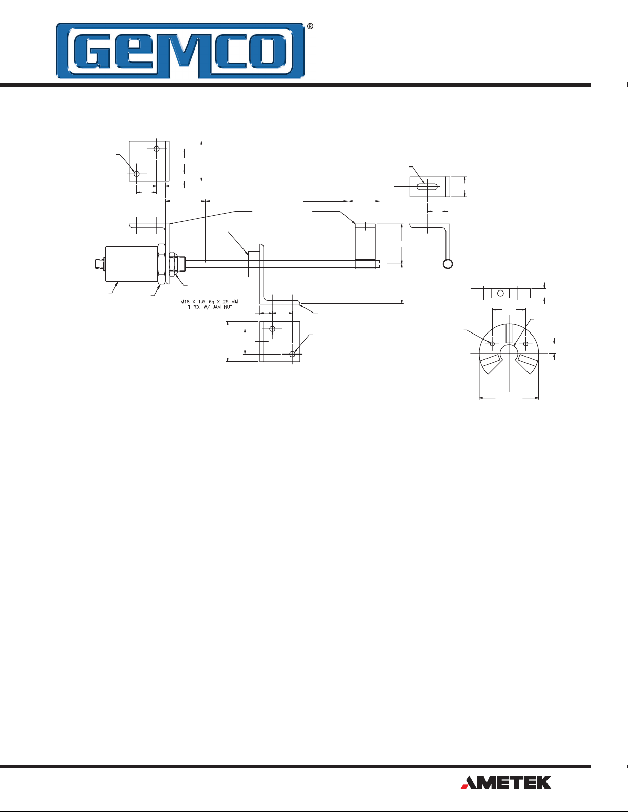
Figure 1-1 953A Dimension Drawing
1080 N. Crooks Road • Clawson, MI 48017 • 800.635.0289 • Phone 248.435.0700 • Fax 248.435.8120 • www.ametekapt.com
®
3
Page 4

AUTOMATION & PROCESS TECHNOLOGIES
Chapter 2: Installing the LDT
!
If a mounting bracket or other part is used that is
made of ferromagnetic material (a material readily
magnetized), it should be placed no closer than 0.25"
from the LDT's rod end to minimize the effects of
magnetic ux distortion. This can cause an inaccurate
measurement of the magnet position.
Non-ferrous materials, such as brass, copper,
aluminum, non-magnetic stainless steel, or plastics,
can be in direct contact with the magnet assembly and
rod end without producing any adverse results.
2.1: Installing the LDT to a
Mounting Bracket
Parts discussed in this section can be found in Figures
1-1 and 2-1.
1. Unscrew the LDT’s jam nut from the threads
protruding from the hex mounting base.
2. Insert the LDT’s rod end into the mounting
bracket’s hole. The mounting bracket may contain
a 3/4-16 UNF-2B or metric M18 x 1.5 threaded
hole. In this case, screw the LDT into this hole
using the threads protruding from the hex
mounting base.
3. Once the LDT is in place, screw the jam nut
back onto the threads of the hex mounting base.
Use the 1.75" hex mounting base on the head
assembly to tighten the LDT to the bracket.
WARNING: Do not use the blue
aluminum cover of the head assembly
to tighten the LDT within the bracket
(see Figure 2-1). This may damage the LDT
and will void your warranty. To tighten the
LDT within the bracket, use the 1.75" hex
mounting base on the head assembly.
If the length of the LDT’s rod end is less than 30”, skip
to the sub-section: Mounting the Magnet Assembly.
Installing Support Brackets
It is recommended that a support bracket be used
with LDTs having a rod 30”-71” in length. Supporting
the end of the rod will minimize operational errors and
protect against damage due to shock and vibration.
If the length of the LDT’s rod is 72” or longer, it is
recommended that additional support brackets be
used. These additional support brackets must be made
of a non-ferrous material. Because these additional
support brackets will interfere with the magnet’s
movement, a special split-type magnet assembly must
be used. To order a split magnet (P/N SD0411200)
and support brackets (P/N SD0411100), contact the
factory at 800-635-0289.
To install a support bracket for a LDT having a rod 30”71” in length, perform step 4a. If the rod is longer than
71”, perform step 4b.
4a. If the support bracket is made of a ferromagnetic
material (material readily magnetized), install the
support bracket no closer than 0.25” from where
the LDT’s dead band ends and the area of stroke
begins. Continue to the sub-section: Mounting
the Magnet Assembly.
To install two or more support brackets for a LDT
having a rod 72" or longer in length, perform the
following steps:
4b. Install support brackets at increments of 48”
throughout the LDT’s rod. Support brackets
placed within the Null Zone and area of stroke or
closer than 0.25” to the beginning of these areas
must be made of a non-ferrous material.
Mounting the Magnet Assembly
Before mounting the magnet assembly, the following
should be considered:
• Ferromagnetic material should not be placed
closer than 0.25” from the LDT’s magnet assembly
or rod end. Failure to do so could cause erratic
operations.
• Minimal clearance between the LDT’s rod and
the magnet assembly through the full stroke is
4
®
1080 N. Crooks Road • Clawson, MI 48017 • 800.635.0289 • Phone 248.435.0700 • Fax 248.435.8120 • www.ametekapt.com
Page 5
AUTOMATION & PROCESS TECHNOLOGIES
2 PLACES
.406
SUPPORT BRACKET SD0411100
.2 8
.4 4
1.00
1.25
.3 7
NUL L
2.00
PROBE MOUNTING KI T
OPTIONA ORL
MAGNE T
STROK E
(P/N 949003)
.28 X 1.03 SLOT
DEAD
BAN D
2.00
C
L
1.00
1.03
3/4-16 JAM NUT
PROB E
NOTES: UNLESS OTHERWISE SPECIFIE D
1.75 HE X
1. MOUNTING KITS FURNISHED WITH
MOUNTING BOLTS.
2. MOUNTING BRACKETS ARE MADE FROM
3/16" X 2" X3" STAINLESS STEEL .
SUPPLIED W/PROB E
OPTIONAL
2.00
1.25
1.00
.6 2
Figure 2-1: Mounting the LDT
required. Stress between the magnet and the rod
can cause exing of the mounting brackets. This
may result in non-linearity.
• LDTs using a split magnet assembly must keep
the diameter of the magnet assembly around the
rod throughout the complete stroke. The diameter
of this magnet assembly should not be more than
0.2” away from the rod. Split magnet assemblies
outside of this range will cause signal loss.
To install the magnet assembly, perform the following
steps:
1. Slide the magnet assembly over the LDT rod.
2. Mount the magnet to the non-ferrous, movable
portion of the device being controlled using nonferrous screws.
MAGNET MOUNTIN G
KIT (P/N 949005)
.2 8
2 PLACES
2.00
.187 THRU
(2 PLACES)
NOTE: USE THIS MAGNET WITH ROD
S
1.407
S
N
N N
2.50 REF .
2.2: Installing the LDT in a
Hydraulic Cylinder
Before installing an LDT in a hydraulic cylinder, note
the following considerations. Items discussed in this
section are found in Figures 1-1 and 2-1.
• A non-ferrous spacer must be used to separate the
magnet assembly from the head of the piston rod.
See Figure 2-2.
• The magnet should not be closer than 2.0” from the
base of the LDT’s hex head when the piston rod is
fully retracted. In instances where space restraints
exist, it may be required to countersink the magnet
into the piston rod. Two magnets are available
for mounting to the piston: the standard 1.29"
in diameter (P/N SD0400800) four-hole magnet
and the 1.0" magnet (P/N SD0410300) designed
exclusively for countersunk mounting applications.
The 1.0" magnet must be secured with a snap ring.
.38
.75 THRU
S S
1080 N. Crooks Road • Clawson, MI 48017 • 800.635.0289 • Phone 248.435.0700 • Fax 248.435.8120 • www.ametekapt.com
®
5
Page 6
AUTOMATION & PROCESS TECHNOLOGIES
• An O-ring is provided at the base of the LDT’s
!
mounting hex for pressure sealing. The O-ring seal
was designed to meet Mil-Std-MS33656. Refer to
SAE J514 or SAE J1926/1 for machining of mating
surfaces.
• A chamfered rod bushing in front of the magnet
may be required. It is recommended that a
chamfered rod bushing be used with LDTs having
a rod 60.0” or longer. This bushing will prevent
wear on the magnet assembly (wear occurs as the
piston retracts from extended lengths). This rod
bushing should be manufactured from a high wear
polymer, such as Teon®.
• It is recommended the bore for the cylinder
piston rod have an inside diameter of at least
0.50”. The LDT rod has an outside diameter of
0.405”. Use standard practices for machining and
mounting these components. Consult the cylinder
manufacturer for details on applicable SAE or
military specications.
It may be necessary to perform machining and
mounting operations on the hydraulic cylinder before
installing the LDT. Consult the information and
specications provided by the cylinder manufacturer
before beginning the following steps:
1. Unscrew the LDT’s jam nut from the threads
protruding from the hex mounting base.
2. Position the non-ferrous spacer against the
piston face, followed by the magnet, and then the
chamfered rod bushing if the LDT’s rod is 60.0” or
longer in length.
If the leading edge of the magnet will come closer
than 2.0” from the base of the LDT’s hex head
when the piston rod is fully retracted, it will be
necessary to counterbore the magnet assembly
into the piston rod. Both the standard 1.29” fourhole magnet assembly (P/N SD0400800) and
the 1.0” magnet assembly (P/N SD0410300) are
designed for counterbored mounting applications.
If it has a 1.0” magnet assembly, a snap ring will
be needed to hold it in place.
4. Insert the LDT’s rod into the hole of the hydraulic
cylinder’s mounting bracket.
The protective Plug may need to be removed from
the hydraulic cylinder before inserting the LDT. The
end cap should contain a 3/4-16 UNF-2B threaded
hole. Screw the LDT into this hole using the
threads protruding from the LDT’s hex mounting
base.
WARNING: Do not use the blue
aluminum cover of the head assembly
to tighten the LDT within the bracket
(see Figure 2-1). This may damage
the LDT and will void your warranty. To tighten
the LDT within the bracket, use the 1.75" hex
mounting base on the head assembly.
With the LDT properly installed inside the hydraulic
cylinder, it may be necessary to assemble parts of the
hydraulic cylinder. For assistance in this task, refer to
the information provided by the cylinder manufacturer.
3. Insert non-ferrous screws through the chamfered
rod bushing (if used), magnet, and non-ferrous
spacer. Secure items by tightening screws.
6
®
1080 N. Crooks Road • Clawson, MI 48017 • 800.635.0289 • Phone 248.435.0700 • Fax 248.435.8120 • www.ametekapt.com
Page 7
AUTOMATION & PROCESS TECHNOLOGIES
S EE N O TE 4
.094 MAX.
1.18
3
4
S TANDARD 4-H O LE MA G NET
0.5” BORE MINIMUM
O-RING SEAL
MAGNET SPACER
O PTI O NAL R O D B US HIN G
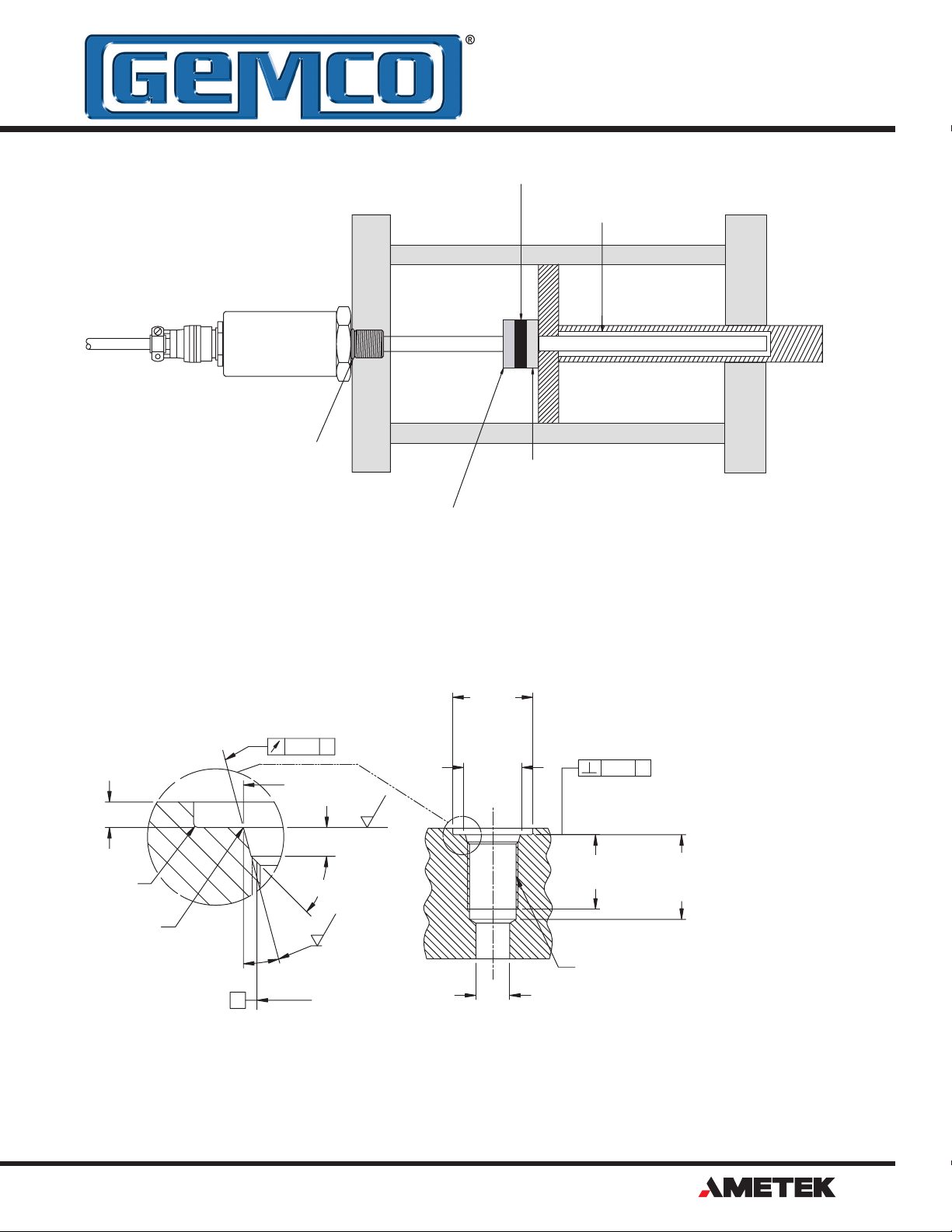
Figure 2-2: Mounting LDT in a Hydraulic Cylinder
R.015
MAX.
R
.008
.004
15°
RECOMMENDE D
MIN. SPOTFAC E
DIAMETER
.004
.813
+/-.002
A
SEE NOTE 1
.866
MINIMU M
SEE NOTE 2
.008
A
125
.106
+/-.008
1.250
SEE NOTE
SEE NOTE
45°
1.100
SEE NOTE 4
125
3/4-16 UNF-2B THREAD
A
PITC H
DIA.
Figure 2-3: Port Detail (SAE J1926/1)
.500
REF.
NOTES:
1. IF FACE OF PORT IS ON A
MACHINED SURFACE,
DIMENSIONS 1.180 AND .094
NEED NOT APPLY AS LONG
AS R.008/.0004 IS
MAINTAINED TO AVOID
DAMAGE TO THE O-RING
DURING ASSEMBLY.
2. MEASURE PERPENDICULARITY TO A AT THIS
DIAMETER.
3. THIS DIMENSION APPLIES
WHEN TAP DRILL CANNOT
PASS THROUGH ENTIRE
BOSS.
4. THIS DIMENSION DOES
NOT CONFORM TO SAE
J1926-1.
1080 N. Crooks Road • Clawson, MI 48017 • 800.635.0289 • Phone 248.435.0700 • Fax 248.435.8120 • www.ametekapt.com
®
7
Page 8

AUTOMATION & PROCESS TECHNOLOGIES
Chapter 3: Wiring
!
!
Once the LDT has been installed, wiring connections
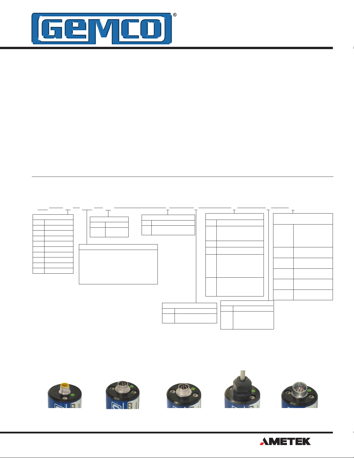
can be made. The VMAX has four different connector
options. Please refer to the part number label to help
identify which wiring diagram is correct. There are two
groups of connections that will need to be made. They
are as follows:
• Power Supply Connections
(including grounding and shielding)
• LDT Input/Output Connections
Power Supply/Ground Connections
The 953A VMAX is available with many different connector/wiring options. Refer to part numbering on unit
in question for proper wiring. See Appendex B for part
numbering grid and qures 3.3 - 3.9 for wiring details.
Connector option S is an industry standard 5 pin
12mm Euro style cordset with a shield. Option B is an
8 pin DIN with a shield, and option M is a 6 pin DIN
with a shield. To reduce electrical noise, the shield
must be properly used. Connect the cable’s shield to
the controller system GND. The cable shield is NOT
connected at the transducer rod. Always observe
proper grounding techniques such as single point
grounding and isolating high voltage (i.e. 120/240
VAC) from low voltage (7-30 VDC cables).
Diagnostic LED
LED Color Description
None No power to LDT
Green Magnet signal detected and within programmed
range.
Yellow Magnet signal detected, but magnet is outside of
programmed range.
NOTE: Magnet can be programmed in this range
if desired.
Red No magnet signal detected. Make sure magnet
is on the rod and within the active area. Move
magnet back into the range and cycle power.
WARNING: Do not use molded cordsets
with LEDs!
It is preferable that the cable between the LDT and
the interface device be one continuous run. If you are
using a junction box, it is highly recommended that the
splice junction box be free of AC and/or DC transientproducing lines. The shield should be carried through
the splice and terminated at the interface device end.
NOTE: When grounding the LDT, a single earth
ground should be connected to the Power Supply
Common (circuit ground). The LDT Power Supply
Common should be connected to the Power Supply
Common (-) terminal. The LDT power supply (+VDC)
should be connected to the power supply positive
terminal (+). The LDT cable shield should be tied to
earth ground at the power supply. The LDT analog
common should not be connected to earth ground and
should be used for connection to interface devices
only. For assistance, refer to your LDT’s wiring drawing
in this chapter.
In order for the VMAX to operate properly, the external
power supply must provide a voltage between 7-30
VDC. The power supply must be rated at one watt
minimum. The power supply should provide less than
1% ripple with 10% regulation.
Single ended
power supply
WARNING: Do not
route the VMAX
cable near high
voltage sources.
Pin 1 (brown) Pin 3 (blue)
7-30 VDC
+ COM
Figure 3-1: Power Supply Wiring
The power supply should be dedicated to the
VMAX to prevent noise and external loads from
affecting it. When powering up more than one
VMAX on a single power supply, each unit will draw
approximately one watt.
3.1: V0/V1 (Voltage)
The LDT generates a voltage output based on position.
The 953 VMAX offers 16 Bits of resolution, and is
fully programmable over the entire active stroke
length. Keep in mind that there is a 2” Null Zone at the
connector end of the LDT and a 2.5” Dead Band at the
other end of the LDT that the magnet must stay out
of at all times. The units come fully programmed from
the factory and do not require re-programming unless
desired.
The analog output is referenced to the analog common
terminal and should not be referenced to any of the
other common terminals. For wiring, see Figure 3-2.
For programming Zero and Span, See Section 3.3.
3.2: C4/C2 (Current)
The LDT generates a current output based on position.
The 953 VMAX offers 16 Bits of resolution, and is fully
programmable over the entire active stroke length of
the LDT. Keep in mind that there is a 2” Null Zone at
the connector end of the LDT and a 2.5” Dead Band at
the other end of the LDT that the magnet must stay out
of at all times. The units come fully programmed from
the factory and do not require re-programming unless
desired.
8
®
1080 N. Crooks Road • Clawson, MI 48017 • 800.635.0289 • Phone 248.435.0700 • Fax 248.435.8120 • www.ametekapt.com
Page 9
AUTOMATION & PROCESS TECHNOLOGIES
Typical Wiring
Figure 3-2 shows two common methods for wiring the
953A to a customer supplied interface device, such
as a PLC or panel meter. The two different methods
are commonly referred to as Single Ended Input or
Differential Input. Differential Input is the preferred
wiring method.
With the Differential Input, the Analog Common wire is
connected to the customer supplied input device and
the Power Supply Common is wired separately to the
customers supplied power source. When wired using
the Differential method, the electrical noise and
voltage offset errors produced by the currents running
through the Power Supply Common are eliminated.
The Power Supply Common and Analog Common are
internally connected inside of the 953A VMAX LDT.
Cable # 949011LXX
NOTE: XX= Length in feet
AUTOMATION & PROCESS TECHNOLOGIES
TM
Power
Supply
7-30 VDC
Customer
Supplied Power
+
Power
Supply Common
_
Program Input
953A
LDT
Position
Output
Position
Common
+ Input
- Input
Differential Input
Power
Supply
7-30 VDC
Customer
Supplied Power
+
Power
Supply Common
_
Program Input
953A
LDT
Position
Output
+ Input
Common
Single Ended Input
Figure 3-2: Current Sourcing
The 953A-C is current sourcing which allows
the current to ow from the LDT into the users
equipment.
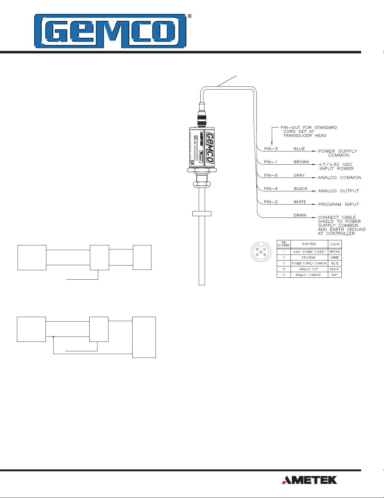
1
2
5
4
3
LDT
Connector
View
Figure 3-3: Wiring for Connector
Option "S", 5 Pin Micro
1080 N. Crooks Road • Clawson, MI 48017 • 800.635.0289 • Phone 248.435.0700 • Fax 248.435.8120 • www.ametekapt.com
®
9
Page 10

AUTOMATION & PROCESS TECHNOLOGIES
AUTOMATION & PROCESS TECHNOLOGIES
TM
10
Figure 3-4:
Wiring for Connector
Option "C", Integral Cable Assembly
®
1080 N. Crooks Road • Clawson, MI 48017 • 800.635.0289 • Phone 248.435.0700 • Fax 248.435.8120 • www.ametekapt.com
Figure 3-5:
Wiring for Connector
Option "H", High Temp Integral Assembly
Page 11
AUTOMATION & PROCESS TECHNOLOGIES
!
Cable # SD0553400LXX
NOTE: XX= Length in feet
Cable # SD0553300LXX
NOTE: XX= Length in feet
AUTOMATION & PROCESS TECHNOLOGIES
TM
AUTOMATION & PROCESS TECHNOLOGIES
TM
1080 N. Crooks Road • Clawson, MI 48017 • 800.635.0289 • Phone 248.435.0700 • Fax 248.435.8120 • www.ametekapt.com
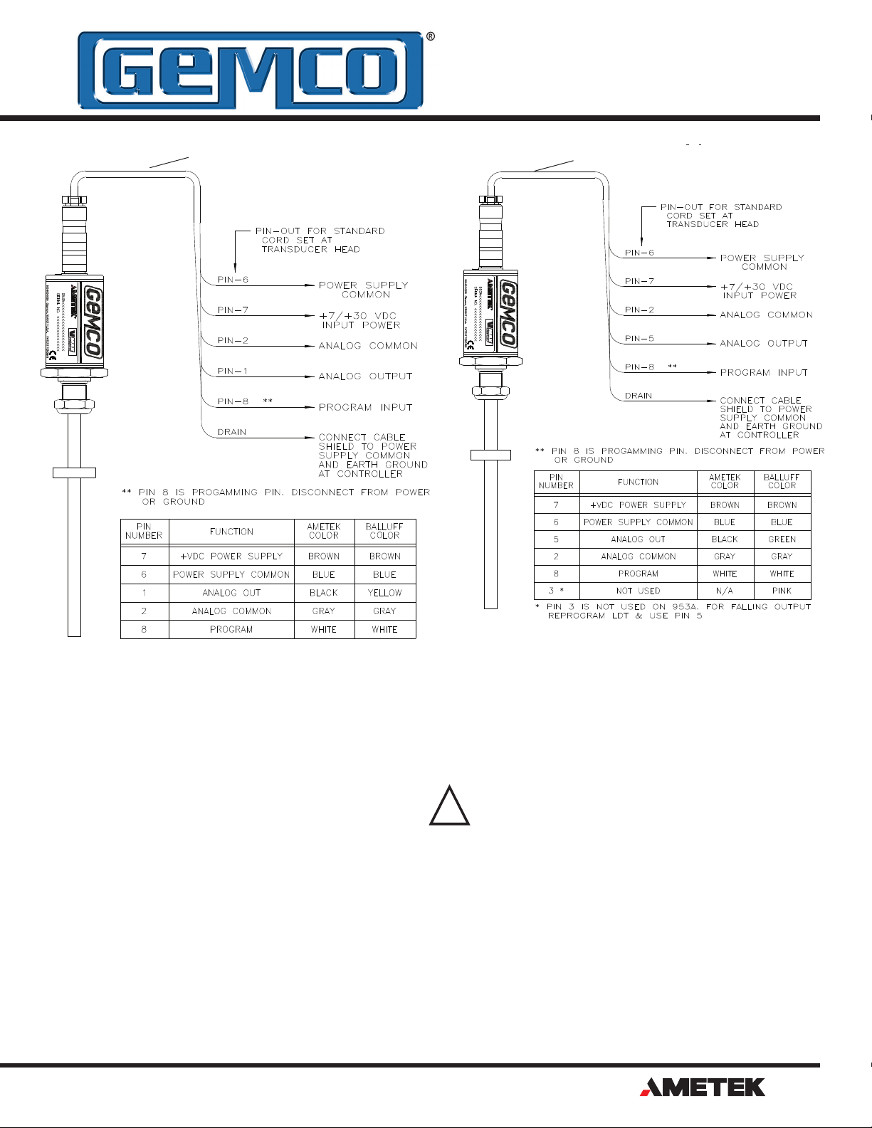
Figure 3-6:
Wiring for Connector
Option "B", 8 Pin DIN,
Current Output
CAUTION: Pinout is different for
voltage vs. current models with
connector option "B"
Figure 3-7:
Wiring for Connector
Option "B", 8 Pin DIN,
Voltage Output
®
11
Page 12

AUTOMATION & PROCESS TECHNOLOGIES
Cable # SD0439700LXX
NOTE: XX= Length in feet
AUTOMATION & PROCESS TECHNOLOGIES
AUTOMATION & PROCESS TECHNOLOGIES
TM
TM
Cable # SD0553200LXX
NOTE: XX= Length in feet
12
Figure 3-8:
Wiring for Connector
Option "E", 10 Pin MS Connector
®
1080 N. Crooks Road • Clawson, MI 48017 • 800.635.0289 • Phone 248.435.0700 • Fax 248.435.8120 • www.ametekapt.com
Figure 3-9:
Wiring for Connector
Option "M", 6 Pin DIN
Page 13

AUTOMATION & PROCESS TECHNOLOGIES
!
3.3: Features
Automatic Gain Control
The Automatic Gain Control feature will automatically
search and nd the magnet on power up, if power is
applied without a magnet on the LDT, the LED will turn
RED indicating no magnet signal is detected. Turn
power off and place magnet within the active stroke
area. Re-apply power.
Diagnostic LED
LED Color Description
None No power to LDT
Green Magnet signal detected and within programmed
range.
Yellow Magnet signal detected, but magnet is outside of
programmed range.
NOTE: Magnet can be programmed in this range
if desired.
Red No magnet signal detected. Make sure magnet
is on the rod and within the active area. Move
magnet back into the range and cycle power.
Accessories
P/N Description
949011L6 6 Foot, 5 Pin, Straight, 12mm, Euro Connector
949012L6 6 Foot, 5 Pin, Right Angle, 12mm, Euro Connector
SD0439700LXX 10 Pin, Straight Connector, 6 Foot Standard
SD0439700LXX 10 Pin, Right Angle Connector, 6 Foot Standard
SD0553200LXX
SD0553300LXX
SD0553400LXX
SD0400800 Standard 4 Hole Magnet
Consult factory for complete accessory offerings.
MTS-6 Pin, "M" Option, (Voltage or Current Outputs)
Balluff-8 Pin, "B" Option, (Voltage Outputs Only)
Balluff-8 Pin, "B" Option, (Current Outputs Only)
3.4: Setting Zero & Span Position
The units come fully programmed from the factory and
do not require re-programming unless desired. The
units are 100% absolute and will not lose programmed
parameters on power loss. The Zero and Span points
can be programmed in any order and anywhere within
the LDT's active sensor area.
NOTE 1: Zero or Span can be adjusted individually
without setting the other.
NOTE 2: Zero = 0V on 0-10 VDC units and 4mA
on 4-20mA units.
There is a timing sequence that is used to unlock the
probe for programming. This is to insure that the Span
cannot be accidentally re-programmed by someone in
the eld.
Before programming the Zero or Span, the program
input must be connected to the Power Supply
Common for a minimum of 2 seconds and no more
than 6 seconds, then released for 1 second. The
LTD programming sequence is now unlocked and
will remain an unlocked unit until either the Zero or
Span is programmed or the 10 second programming
sequence times out. During the unlock mode either
the Zero or Span can be programmed by momentarily
connecting the Program Input to either the Power
Supply Common or Power Supply +.
NOTE: The LDT must be unlocked to program the
Zero and unlocked again to program the Span. Once
either the Zero or Span is programmed the LDT will go
back into the locked mode.
To program the Zero or Span, the program input must
be connected to the Power Supply Common for 4
seconds, then released for 1 second. Within the next 5
seconds, you can program either the Zero or the Span
by momentarily connecting the Program Input to either
the Power Supply Common or Power Supply +VDC.
WARNING: During normal operation,
electrically insulate the White
Program wire to prevent accidental
setting of Span.
Manual Setting of Zero & Span
To set the Zero and Span position, follow these steps:
1. Apply power to the LDT.
2. Place magnet assembly where Zero is to be
located, but within the active region of the probe.
3. Short the Program Input pin to the Power Supply
Common for 4 seconds. Remove the short for 1
second. Within 5 seconds, short the Programming
Input pin to the Power Supply Common. This
completes the Zero programming process.
4. Place magnet assembly where Span is to be
located, but within the active region of the probe.
5. Short the Program Input pin to the Power Supply
Common for 4 seconds. Remove the short for 1
second. Within 5 seconds, short the Programming
Input pin to the Power Supply +VDC.
This completes the programming process.
1080 N. Crooks Road • Clawson, MI 48017 • 800.635.0289 • Phone 248.435.0700 • Fax 248.435.8120 • www.ametekapt.com
®
13
Page 14

AUTOMATION & PROCESS TECHNOLOGIES
Optional Remote Tester & Programmer
Optional In-Line Programmer
The battery operated remote tester / programmer is
available in either a voltage or current model. P/N
SD0528810 is designed for voltage
units while SD0528811 is for current
units. Both units are designed to
work with connector option S only.
These units are typically used to
demonstrate the functionality of the
LDT in the eld, however, they can
be used as a handy troubleshooting
/ programming device.
1. Attach the 5 pin Euro connector
to the VMAX.
2. Push the toggle switch to the ON position to power
the LDT.
3. Place magnet assembly where Zero is to be
located, but within the active region of the probe.
4. Push the black Zero button for 4 seconds,
release for 1 second. Within 5 seconds, push
the Zero button again. This completes the Zero
programming process.
5. Place magnet assembly where Span is to be
located, but within the active region of the probe.
6. Push the black Zero button for 4 seconds, release
for 1 second. Within 5 seconds, push the Span
button.
NOTE: This time the Span button is pushed for the
nal programming step.
This completes the programming process.
The 955-1409 is a remote
programmer that can help
simplify the programming
process. The programmer
is a portable device
that can be temporarily or permanently
installed in series with the VMAX with
connector option S.
1. Remove the 5 pin cordset to the LDT.
2. Attach the existing cordset to the 955-1409
programmer.
3. Attach the other end to the LDT.
4. Apply power to the LDT.
5. Place magnet assembly where Zero is to be
located, but within the active region of the probe.
6. Push the Zero button for 4 seconds. Release the
button for 1 second. Within 5 seconds, push the
Zero button again.
7. Place magnet assembly where Span is to be
located, but within the active region of the probe.
8. Push the Zero button for 4 seconds. Release the
Zero button for 1 second. Within 5 seconds, push
the Span button.
Appendix A: Troubleshooting
A Tri-color LED is conveniently located next to the
connector to help with set-up and diagnostics.
Diagnostic LED
LED Color Description
None No power to LDT
Green Magnet signal detected and within programmed
range.
Yellow Magnet signal detected, but magnet is outside of
programmed range.
NOTE: Magnet can be programmed in this range
if desired.
Red No magnet signal detected. Make sure magnet
is on the rod and within the active area. Move
magnet back into the range and cycle power.
If a problem exists after reading this section, please
contact our technical support department.
General Checks
Make sure that the magnet is located within the
LDT’s active stroke area. Keep in mind that the LDT
is programmable over the entire active stroke area.
Captive magnet assemblies should be positioned
so that they can move freely over the entire area of
the active stroke without binding or pushing on the
rod end. Non-captive magnet assemblies should be
situated so that the magnet is no farther than 0.2”
from the rod at any point in the magnet assembly’s
movement.
14
®
1080 N. Crooks Road • Clawson, MI 48017 • 800.635.0289 • Phone 248.435.0700 • Fax 248.435.8120 • www.ametekapt.com
NOTE: Ferromagnetic material (material readily
magnetized) should be located no closer than 0.25”
from the magnet or LDT rod end. This includes
mounting brackets, magnet spacers, magnet brackets,
and mounting screws. Ferromagnetic material can
distort the magnetic eld, causing adverse operation or
even failure of the LDT.
Check all LDT wires for continuity and/or shorts. It
is preferred that the cable between the LDT and the
interface device be one continuous run. If you are
using a junction box, it is highly recommended that the
splice junction box be free of AC and/or DC transientproducing lines. The shield should be carried through
the splice and terminated at the interface device end.
Power Supply Checks
This section will help you to determine if your power
supply is adequate for the LDT to operate properly, or
if the LDT’s cable has a short or open.
In order for the VMAX to operate properly, the external
power supply must provide a level between 7-30 VDC.
A power supply providing voltage above this specied
range may damage the LDT. A power supply providing
power below this specied range will not be sufcient
Page 15
AUTOMATION & PROCESS TECHNOLOGIES
Appendix B: Part Numbering
to power the LDT. When powering more than one
VMAX on a single power supply, remember that each
unit requires approximately one watt of
power. The amount of current draw will vary based on
the input voltage used. To calculate the current draw
for a particular LDT, divide the LDT wattage by the
input voltage. For example, 1 watt divided by 24 VDC
equals 41.6mA.
NOTE: LDT’s with integral cable assemblies
should be checked for proper voltage at the power
supply terminals. This cable assembly cannot be
removed from the LDTIf the reading is between 7
and 30 VDC, turn power supply off and go to step
7. If the reading is below 7 VDC, either the power
supply is not providing enough power or the LDT’s
cable possibly has a short or open. A reading of
no voltage or minimal voltage (less than 5 volts)
may be due to a short or open in the cable. If the
If the LDT is not operating properly, the LDT’s cable
may have an open or short, or the power supply is not
supplying sufcient power. To verify this:
1. Turn the power supply off.
2. Remove the mating connector from the LDT.
3. Turn the power supply on.
4. Using a digital voltmeter, check across Power Supply
Common and customer supplied power (+VDC) on
the mating end of the cable for a level between 7 and
30 VDC.
reading is not between 7 and 30 VDC, go to step
5. If the reading is above 30 VDC, adjust power
supply or replace.
5. Turn the power supply off.
6. Check the continuity of the individual wires of
the cable between the power supply and the
LDT. Check for continuity from one end of the
cable to the other. Also, verify that no shorts
exist between pins.
7. Reconnect the mating connector to the LDT.
Appendix B: Part Numbering
953A 0120V0 X
Output
V0
0 to 10 VDC
V1
10 to 0 VDC
V2
-10 to 10 VDC
V3
10 to -10 VDC
V4
0 to 5 VDC
V5
5 to 0 VDC
V6
-5 to 5 VDC
V7
5 to -5 VDC
C4
4 to 20mA
C2
20 to 4mA
NOTE 1: On unsupported stroke
lengths greater
than 4 feet, rod support bracket(s)
and a special magnet
should be used.
NOTE 2: Specify magnet as separate line item.
Standard magnet is SD0400800.
Insert stroke length to 0.1 inch. Enter as a fourplace number. Example: A 12.0” stroke enters as
0120.
OR
Insert stroke in millimeters to 1mm. Enter as a
four-place number. Example: 305mm stroke entered
as 0305M. Metric length includes metric mounting,
M18x1.5. Unless specified otherwise.
Units
Blank
M
VP
Inches
Metric Base
and Threads
Stroke Length
Null Zone
X
Standard 2 inches.
Insert non-standard Null
N_
Zone (1.5" Minimum).
D_
Dead Band
X
Standard 2.5 inches.
Insert non-standard Dead
Band (2.25" Minimum).
S
C_
M
B
E
H_
SXX
Connector Option
Standard 5 Pin, 12mm Euro
Integral Cable Assembly.
Insert length in feet. Example:
C6 = 6 foot cable.
6 Pin DIN, MTS Style D60
8 Pin DIN, Balluff S32
Environmental 10 Pin MS
Connector compatible w/951 &
952 LDTs
w/connector option “E”.
o
High Temp., Integral cable
assembly 200 C Teflon Cable.
Insert length in feet. Example: H6=
6 foot High Temp Teflon Cable.
Options
X
None
Stainless Steel cover and
connector. Only available
S
with connector options S,
C and H.
Optional Housing Style
Mounting Threads
Raised face hex base
Blank
(Standard) - Threads will
be the same as "Units
of Measure" unless
specified otherwise.
US Threads with raised
R
face hex base
US Threads with flat
F
face hex base
Metric Threads with
M
raised face hex base
Metric Threads with flat
N
face hex base
Sensor cartridge only
C
No hex base
5 Pin Micro, 12mm Euro
1080 N. Crooks Road • Clawson, MI 48017 • 800.635.0289 • Phone 248.435.0700 • Fax 248.435.8120 • www.ametekapt.com
S Connector Style
M Connector Style
6 Pin DIN, Fits MTS D60
B Connector Style
8 Pin DIN, Fits Balluff S32
C Connector Style
Integral Cable Assembly
E Connector Style
10 Pin MS Connector,
Fits Gemco 951 & 952 Wiring
®
15
Page 16
AUTOMATION & PROCESS TECHNOLOGIES
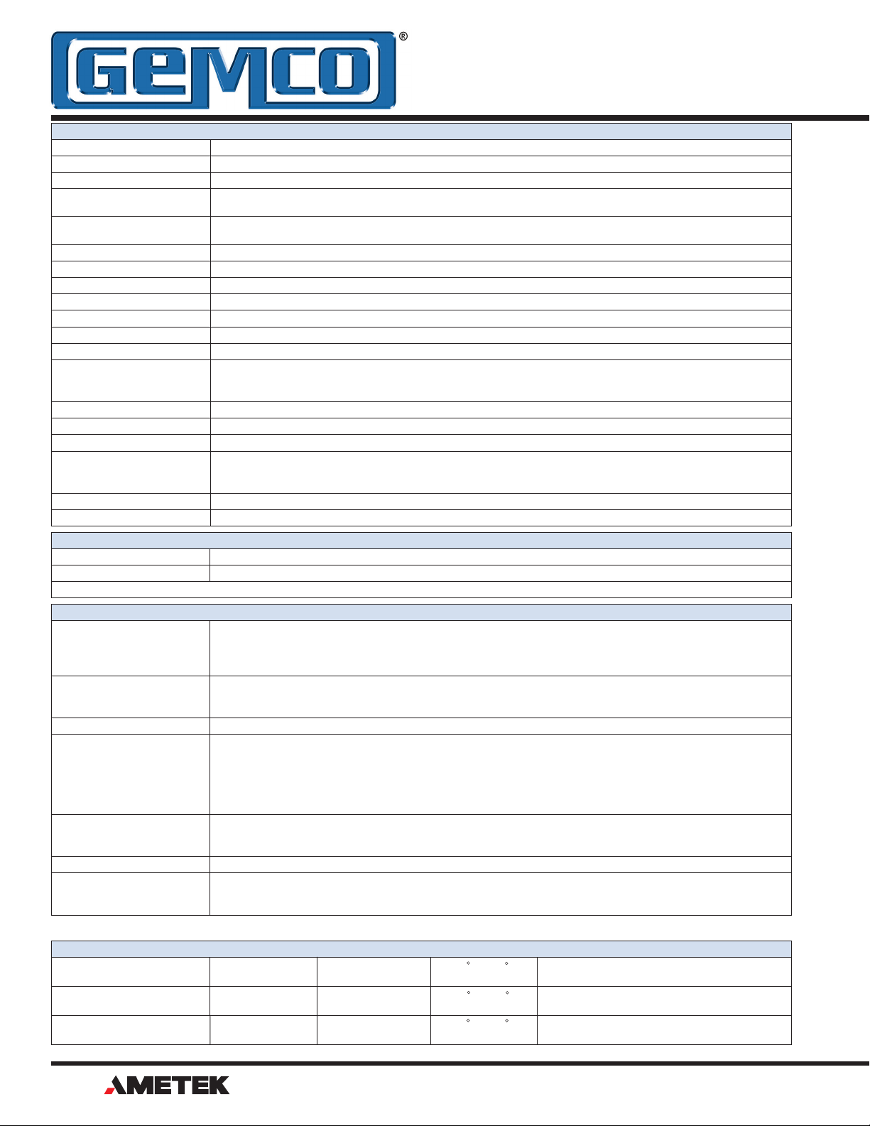
Appendix C: Specications
General Specications
Rod End 316 Stainless Steel, 0.405" (10.29 mm) outer diameter
Mounting Hex 316 Stainless Steel, 1.75" (44.45 mm) across ats, IP68
Mounting Threads 3/4" (19.05 mm) x 16 x 1.00" (25.4 mm) with ESNA jam nut and O-ring seal. Optional M 18x 1.5 Metric threads
Head Assembly Thick wall aluminum cover with Viton O-ring standard, gasket seal at the base and connector exit, IP68 IEC
Head Enclosure 3.2" (81.3 mm) long with 1.75" (44.45 mm) diameter- Note: See pg. 3 for connector option "E" Head enclosure
Connector 5 pin 12mm Euro/Micro standard. Intergrated cable assembly, 6 pin or 8 pin DIN & 10 pin MS optional.
Displacement 1" to 300"
Dead Band 2.50" (63.5 mm) standard (cannot be less than 2.25")
Null Zone 2.00" (50.8 mm) standard (cannot be less than 1.5")
Linearity Less than +/- 0.01% or +/- 0.005", whichever is greater. (+/- 0.002" typical)
Repeatability Equal to Resolution
Hysteresis 0.001"
Operating Temperature
Head (Electronics)
Guide Tube
Storage Temperature -40° to 221° F (-40° to 105° C)
Operating Pressure 3,000 psi constant, 8,000 psi spike
Guide Tube Pressure 5,000 psi constant, 10,000 psi spike
Shock & Vibration
Shock
Vibration
Zero & Span Adjustability Factory set at Null Zone & Dead Band locations. Field re-settable at any location within active stroke.
Approvals CE, 89/336/EEC (EMC)
Input Voltage 7-30 VDC
Current Draw One watt, 40mA at 24 VDC typical
Temperature Drift
Position
Output
Analog Output Loading Voltage output minimum load resistance: 2K ohms
Analog Ripple <1 mV maximum (position output)
Update Time Stroke Length
Resolution
Internal
Output
Position Output 0-10 VDC, 16 Bits (65,535) resolution 4-20mA, 16 Bits (65,535) resolution
Output Type
Voltage
Current
Cable Type Gauge Jacket Temp Bend Radius
Connector Options
"S", "M", "B", "C"
High Temp Integral Cable
"H" option
Connector Option "E" 22 Polyurethane -50 to 105 C Moving Applications - 2.3"
Fixed applications - 1.2"
600529, stainless steel cover optional
dimensions.
-40° to 185° F ( -40° to 85° C)
-40° to 221° F (-40° to 105° C)
1,000Gs (lab tested) IEC 60068-2-27
30Gs (lab tested) IEC 60068-2-6
Electrical Specications
Specications are subject to change and based on a typical 48" stroke length.
Analog Specications
3.1 ppm/° F/in. of stroke2
3.1 ppm/° F for Voltage output
9.2 ppm/° F for Current output
Current output: Guaranteed 5mA minimum for voltage units
Maximum load resistance: 500 ohms
L ≤ 2”
2” < L ≤ 12”
12” < L ≤ 30”
30” < L ≤ 50”
50” < L ≤ 100”
0.00006" (1.524 microns)
16-Bit
V0- 0 to 10 VDC, V1- 10 to 0 VDC, V2- -10 to 10 VDC, V3- 10 to -10 VDC, V4- 0 to 5 VDC, V5- 5 to 0 VDC,
V6- -5 to 5 VDC, V7- 5 to -5 VDC, C4- 4 to 20mA, C2- 20 to 4mA
22 PVC -50 to 105 C Moving Applications - 2.36"
Fixed applications - 1.18"
22 Teon -70 to 200 C Moving Applications - 4.6"
Fixed applications - 2.3"
Update Time
0.5 ms
1 ms
2 ms
3 ms
4 ms
Stroke Length
100” < L ≤ 150”
150” < L ≤ 180”
180” < L ≤ 250”
250” < L ≤ 300”
Cable Specications
Update Time
5 ms
6 ms
7 ms
8 ms
16
®
1080 N. Crooks Road • Clawson, MI 48017 • 800.635.0289 • Phone 248.435.0700 • Fax 248.435.8120 • www.ametekapt.com
Page 17

Part Number
Serial Number
Purchase Order Number
Sales Order Number
Comments
NOTES:
Page 18

AUTOMATION & PROCESS TECHNOLOGIES
®
Other Products
Copyright 2012 by AMETEK Automation & Process Technologies. All Rights Reserved. Made in the USA.
®
1080 N. Crooks Road, Clawson, MI 48017-1097
Phone: 248.435.0700 Toll Free: 800.635.0289
953A.M3R
4/12.Z191
Fax: 248.435.8120 www.ametekapt.com
 Loading...