

Page 1
Page 2

Principles of Operation
The Series 925 Linear Cable Reel can be used in any linear application up to 1200 inches.
The system consists of a heavy duty spring motor assembly attached to a precision
machined cable drum. As the cable is pulled off of the precision drum, the drum rotates
a shaft connected to it. This shaft is precisely geared such that the full number of
revolutions of the drum is equal to the appropriate number of revolutions required by
the chosen sensor.
Applications
The Series 925 can be used in any industrial application to monitor a linear or reciprocating machine motion.
The sensor package, along with the associated electronics (i.e. programmable logic control
ler, programmable limit switch, counter card, etc.) can sense the position of any linear
motion and can, therefore, be used to control machines.
Advantages
-
This approach to machine positioning has several advantages over traditional limit
switches. In hostile environments, such as many steel mill applications, the cable reel
sensor can be mounted remotely. This protects the sensor from excessive heat, steam,
water, chemicals and physical damage. In addition, mounting alignment is not critical
in that the cable can be mis-aligned somewhat without harm, thus saving installation
time. The variety of sensors available allows the system to be easily integrated to existing
machine controls.
Page 3
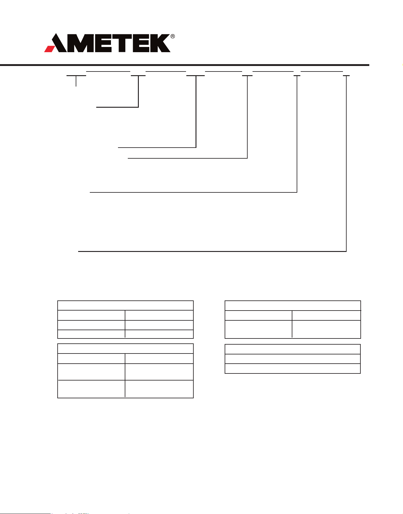
Part Numbering
925 A1
Cable Reel
Sensor
Hardware Type
A1 = 0 - 96 inch Stroke
A2 = 97 - 192 inch Stroke
B1 = 193 - 480 inch Stroke Single Spring
B2 = 193 - 480 inch Stroke Double Spring
C = 481 - 1200 inch Stroke
Active Stroke in Inches
Initial Cable Lead in Inches
First 72 inches of intial lead is no charge. Cable lead
above 72 inches an additional charge per inch.
Leave blank if no initial cable lead required.
Sensor Type
S = Single-turn Resolver
M = Multi-turn Resolver
P1 = Single-turn Potentiomenter
P2 = Multi-turn Potentiometer
E1 = Provision for an Incremental Encoder*
E2 = Provision for an Absolute Sensor*
DN = Single-turn Resolver with DeviceNet Interface
CO = 4 - 20mA Output (Resolution is 1,000 points of total stroke)
100
12
S
X
Options
X = None
* In instances where provisions for a customer supplied sensor are required, the following points must be covered:
A. A detailed dimension drawing of the sensor to be coupled must be supplied
B. A custom dimension/approval drawing will be made prior to manufacturing.
C. Special gearing of sensor may require an additional charge.
Sheave Assemblies
Description Part Number
Horizontal
Vertical
PSD0102600
PSD0102500
Description
Resolver & Mating
Connector
Replacement Spring Assembly
Description
Spring motor for A1&
A2 Style Units
Spring motor for B &
C Style Units
Points to note when ordering a linear cable reel sensor:
1. Hardware types determine the maximum capable stroke of each style. The actual stroke is customer specified. Three
initial wraps minimum remain on cable drum after the stroke length is reached. Pulling the cable out to its physical
maximum length may damage the unit.
Part Number
M0352900
SD039220
Resolver
Part Number
SD0308900
Cable Assembly
Part Number
SD0414600L__
2. Standard gearing of single-turn sensors is such that the active stroke of the cable reel will rotate the sensor 350 degrees.
Multi-turn sensors will rotate the maximum number of turns over the active stroke. Requests for gearing other than the
above must be called out clearly on order.
3. Mounting of customer supplied sensors is done in the most expedient way possible. Special mounting requirements
must be specified clearly on order.
Page 4

1.86
.42
THROAT
CLEAR
VIEW "A"
.19
Dimensions
“A” Version (stroke 96” or less)
2.50
.20
2.11
SEE VIEW "A"
1.50
.26
5.94
6.46
.50
.38 SLOT
4 PLACES
ACTIVE
STROKE
AS SPECIFIED
6.13
5.08
1.86
.42
THROA
CLEAR
VIEW "A"
.19
T
SPECIFY INITIAL
CABLE LEAD
.20
2.11
CABLE
REPLACEMENT
ACCESS
1.48
5.06
8.04
“A” Version (stroke 97” to 192”)
2.50
1.50
SEE VIEW "A"
.26
6.48
5.94
.50
.38 SLOT
4 PLACES
GEAR REDUCER ACCESS
CONNECTOR
(MS-3102E-16S-1P)
ACTIVE
STROKE
AS SPECIFIED
6.13
5.08
GEAR REDUCER ACCESS
SPECIFY INITIAL
CABLE LEAD
E
CABL
REPLACEMENT
ACCESS
9.25
5.06
CONNECTOR
(MS-3102E-16S-1P)
Page 5

3.12
Dimensions
“B” Version
16.00
15.00
INITIAL CABLE LEAD
2.00
STANDARD
7 PIN
CONNECTOR
3.12
1.89
5.18
12.82
.41
4 PLACES
SEE VIEW "A"
3.19
* *
“C” Version
ADD 1.75 (FOR
"B2" STYLE UNITS
11.47
1.86
8.50
VIEW "A"
2.11
.19
.42
THROAT
CLEARANCE
.20
18.60
19.60
N
7 PI
CONNECTOR
2.00
1.89
6.34
15.22
.41
4 PLACES
SEE VIEW "A"
4.94
1.86
.42
THROAT
CLEAR
10.69
VIEW "A"
2.11
.19
.20
Page 6

Sensor Type
Single Turn Resolver
Cable reel sensor with single turn resolvers are
setup so that the full stroke of the cable reel is
equal to approximately 350 degrees rotation of
the resolver. The resolver signal is fed to a converting device, like the Gemco Series 2500 PLS.
The Series 2500 can be scaled to display the
linear motion of the cable reel sensor. Example:
A 20 ft.. stroke cable reel sensor is specified
to be used with our Series 2500 PLS. Desired
accuracy is .01 ft. By calculating a scale factor
based on 360 degrees rotation of the resolver
such that 2000 counts or (20.00 ft.) is obtained
at 350 degrees, full linear display is achieved.
Stroke Range
Mechanical Accuracy
Speed Range
Cable Tension
Cable Material
Housing Material
Seal
Temperature Range
Specifications
Up to 1200 inches (100 ft.) standard
0.05% of active stroke
Variable
Type A unit 2.5 lbs. to 4.2 lbs. (stroke to 96”)
Type A unit 1.25 lbs. to 4.2 lbs. (stroke to 192”)
Type B unit 1.6 lbs. to 14.27 lbs.
Type C unit .75 lbs. to 16.30 lbs.
.056” (actual) stainless steel aircraft grade
10 gauge cold rolled sheet steel with baked enamel
paint finish
Splash Proof
Sensor dependent (most encoders and potentiometers
are around 0° to 180° F standard, resolvers are
typically -50° to 250° F). Check manufacturers specs
Multi-Turn Resolvers
In instances where a high degree of accuracy
or a long stroke is required, it may be advantageous to use a multi-turn resolver. The multiturn resolver can generate many counts per
revolution of the cable drum (up to 16,384 with
our Series 2500 electronics) and will accumulate these counts per revolution to track the
total linear travel. By using the linear travel per
revolution of the drum we can formulate a scale
factor for the electronic package that will display
linear cable travel throughout the full stroke.
Encoder and Potentiometer Sensors
When encoders or potentiometers are used we
can formulate the outputs to most any customer
specification. As standard packages potentiometers would be geared so that the full stroke of
the cable reel sensor was equal to approximately
90% of the active rotation on a single turn pot
and approximately 90% of the last turn on a 10
turn pot.
Incremental encoders can be directly driven
off the cable drum to give a known number of
pulses per revolution.
Absolute encoders can be geared so that the
maximum number of counts would equal the
specified linear stroke. If maximum stroke is
exceeded, the encoder will roll through to zero.
Page 7

MOVING
MEMBER
SHEAVE
ASSEMBLIES
CABLE REEL
SENSOR
CABLE REEL
SENSOR
Mounting & Sheave Assemblies
SHEAVE ASSEMBLY
CABLE REEL
SENSOR
G
MOVIN
MEMBER
SHEAVE
ASSEMBLIES
CABLE REEL
SENSOR
MOVIN
DEVICE
G
MOVING
DEVICE
2.00
3.00
1.03
SHEAVE ASSEMBLIES
HORIZONTAL MOUNT
P/N PSD-0102600
.38 DIA. MTG.
HOLES (4 PLACES)
5.47
6.22
VERTICAL MOUNT
P/N PSD-0102500
3.38 DIA.
2.00
0.25
0.70
3.15
2.37
.38 DIA. MTG.
HOLES (4 PLACES)
2.06
2.95
4.05
2.36
0.19
Page 8

AUTOMATION & PROCESS TECHNOLOGIES
®
1080 N. Crooks Road, Clawson, MI 48017-1097
Phone: 248-435-0700 Toll Free: 800-635-0289
Fax: 248-435-8120 www.AMETEKAPT.com
925.B2R
10/05.Z12
 Loading...