

Page 1
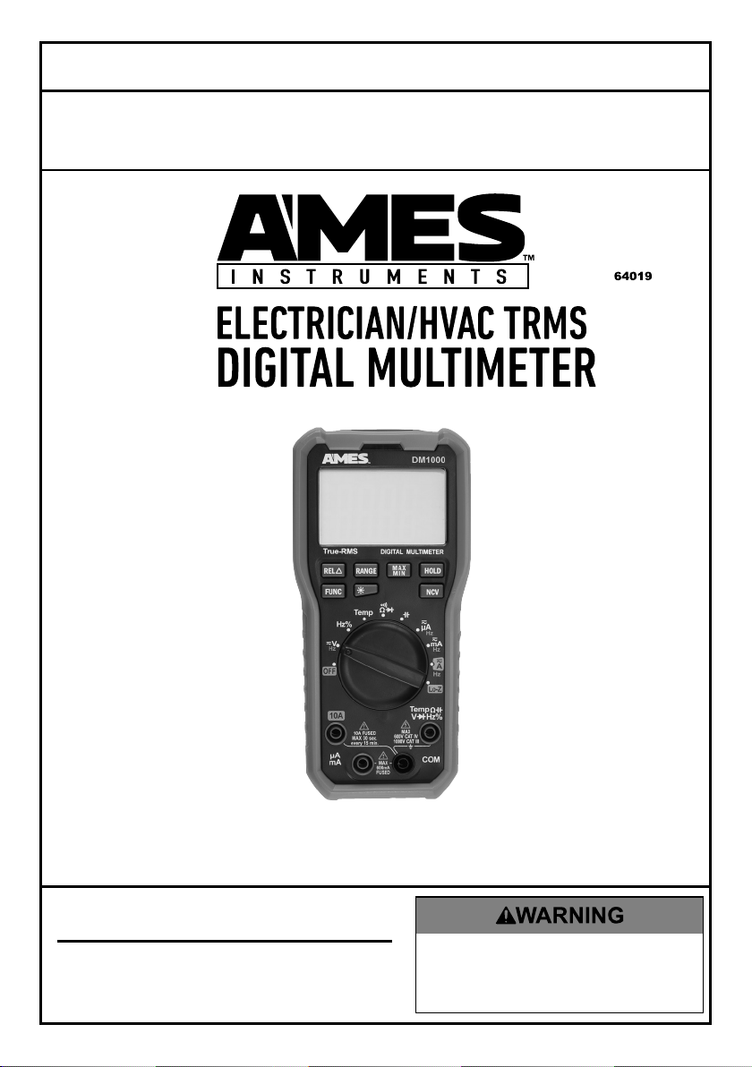
Owner’s Manual & Safety Instructions
Save This Manual%Keep this manual for the safety warnings and precautions, assembly,
operating, inspection, maintenance and cleaning procedures. Write the product’s serial number in the
back of the manual near the assembly diagram (or month and year of purchase if product has no number).
Keep this manual and the receipt in a safe and dry place for future reference. 17i
!"#"$%&'(%)*+#"$*%,$-%.$$/-00)))1.,(+&(2(*"3.$14&5
65,"7%&'(%$*4.8"4,7%#'//&($%,$-%/(&9'4$#'//&($:.,(+&(2(*"3.$14&5
When unpacking, make sure that the product is intact
and undamaged. If any parts are missing or broken,
please call 1-888-866-5797 as soon as possible.
Copyright© 2017 by Harbor Freight Tools®. All rights reserved.
No portion of this manual or any artwork contained herein may be reproduced in
any shape or form without the express written consent of Harbor Freight Tools.
Diagrams within this manual may not be drawn proportionally. Due to continuing
improvements, actual product may differ slightly from the product described herein.
Too l s r e q ui r e d f o r a s s em b l y a n d s e rv i c e m a y n o t b e i n c lu d e d.
;*,9%$."#%5,$*(",7%+*2&(*%'#"83%$."#%/(&9'4$1%
<,"7'(*%$&%9&%#&%4,8%(*#'7$%"8%#*("&'#%"8='(>1%
?@!6%ABC?%D@EF@G1
Page 2
A,+7*%&2%Q&8$*8$#
Safety ..........................................2
Specifications ..............................5
Setup ...........................................6
R@;ECES%?TDUVG?%@EW%W6<CECACVE?
This is the safety alert symbol. It is used to alert you to
potential personal injury hazards. Obey all safety messages
that follow this symbol to avoid possible injury or death.
Indicates a hazardous situation which, if not avoided,
Indicates a hazardous situation which, if not avoided,
Indicates a hazardous situation which, if not avoided,
Addresses practices not related to personal injury.
Operation ..................................... 8
Maintenance ............................... 15
Warranty ..................................... 16
will result in death or serious injury.
could result in death or serious injury.
could result in minor or moderate injury.
Page 2 <&(%$*4.8"4,7%H'*#$"&8#I%/7*,#*%4,77%JKLLLKLMMKNOPO1 Item 64019
Page 3

CDXV;A@EA%?@<6AT%CE<V;D@ACVE
?,2*$>%R,(8"83#%,89%X(*4,'$"&8#
;*,9%,77%#,2*$>%),(8"83#%,89%,77%"8#$('4$"&8#1%%
Failure to follow the warnings and instructions may result
in electric shock, fire and/or serious injury.
?,Y*%,77%),(8"83#%,89%"8#$('4$"&8#%2&(%2'$'(*%(*2*(*84*1
1. Electrical shock can cause death
or injury! NEVER TOUCH exposed
conductors of electricity.
2. A*#$%4,+7*%Y&7$,3*#%)"$.%4,(*1
3. Inspect the Multimeter before
use. In addition to a general
inspection, look specifically for:
a. Pay special attention to the
insulation protecting the connectors.
b. Check the leads for exposed metal,
damaged insulation, and continuity.
c. Replace damaged test lead
immediately, before use.
4. Do not use the Multimeter if:
a. Either of the test leads are
damaged in any way.
b. Test leads are dirty or
have residue on them.
c. The battery is low.
d. Near any explosive
gasses or fumes.
e. Any abnormal operation is
detected.
(If in doubt about the
condition of the Meter, have
it serviced before use.)
f. The battery cover is open.
5. Power this Meter using only
the battery(ies) referenced in
the Specifications Chart.
6. Use caution when working near
voltages above 30 VAC rms, 42 VAC
peak, or 60 VDC. Voltages this high
present a risk of electric shock.
7. Disconnect the circuit’s power
before connecting the Meter in
series, when measuring current.
8. Connect the common (COM) test
lead first and disconnect it last.
9. Hold the probes with fingers
behind guards.
10. Avoid electrical shock. Use extreme
caution when working near uninsulated
conductors or bus bars. Prevent body
contact with grounded surfaces such
as pipes, radiators, ranges, and cabinet
enclosures when testing voltages.
11. Observe work area conditions. Do
not test voltages in damp or wet
locations. Don’t expose to rain.
Keep work area clean and well lit.
12. Keep children away. Children must
never be allowed in the work area.
13. Stay alert. Watch what you are doing,
use common sense. Do not operate
any meter when you are tired.
14. Do not operate meter if under the
influence of alcohol or drugs. Read
warning labels on prescriptions to
determine if your judgment or reflexes
are impaired while taking drugs. If there
is any doubt, do not operate the meter.
?@<6ATVX6;@ACVED@CEA6E@EQ6 ?6AFX
Page 3<&(%$*4.8"4,7%H'*#$"&8#I%/7*,#*%4,77%JKLLLKLMMKNOPO1Item 64019
Page 4

15. People with pacemakers should
consult their physician(s) before
use. Electromagnetic fields in close
?@<6AT VX6;@ACVE D@CEA6E@EQ6?6AFX
proximity to heart pacemaker could
cause pacemaker interference
or pacemaker failure.
16. Do not test voltage on circuits
higher than 1000 volts.
17. Do not test current on circuits
higher than 10 amps.
18. Dress properly. Protective,
electrically nonconductive
clothes and nonskid footwear are
recommended when working.
19. Wear ANSI-approved safety
goggles during use.
20. Only use accessories intended
for use with this meter.
21. Avoid damaging meter. Use only
as specified in this manual.
22. Prior to testing resistance, diodes,
or continuity; disconnect all power
to the circuit and discharge all
high-voltage capacitors.
23. Performance of this meter may vary
depending on battery condition.
24. Use the proper settings, terminals,
techniques, and range for the
tests performed. Start with the
range stated in the instructions.
25. Do not apply voltage to the Test
Leads when the Multimeter is in
the Ohms testing setting. Damage
can occur to the Meter.
26. Do not switch between testing
modes with the multimeter
connected to a circuit.
27. Do not use the meter at a setting
marked as blank on the scale.
28. Have the Multimeter calibrated by
a qualified technician every year
to maintain accurate results.
29. Do not disassemble charger;
take it to a qualified technician
when service or repair is required.
Incorrect reassembly may result
in a risk of electric shock or fire.
30. The warnings, cautions, and
instructions discussed in this
instruction manual cannot cover all
possible conditions and situations
that may occur. It must be understood
by the operator that common sense
and caution are factors which cannot
be built into this product, but must
be supplied by the operator.
%?@!6%AB6?6%CE?A;FQACVE?1
Page 4 <&(%$*4.8"4,7%H'*#$"&8#I%/7*,#*%4,77%JKLLLKLMMKNOPO1 Item 64019
Page 5
?/*4"2"4,$"&8#
DC Voltage Ranges: 660mV / 6.6V / 66V / 660V / 1000V
DC Voltage Accuracy (@660mV) ± 0.8% of rdg + 3D
(@6.6V - 660V) ± 0.5% of rdg + 5D
(@1000V) ± 0.8% of rdg + 3D
DC Current Ranges: 660μA / 6600μA / 66mA / 660mA / 10A
DC Current Accuracy (@660μA - 660mA) ± 1.0% of rdg + 5D
(@10A) ± 2.0% of rdg + 5D
AC Voltage Ranges: 660mV / 6.6V / 66V / 660V / 1000V
Frequency Range:
(@660mV) 40-60Hz;
(@6.6V - 1000V) 40-400Hz
AC Voltage Accuracy (@660mV) ± 1.5% of rdg + 5D
(@6.6V - 66V) ± 1.2% of rdg + 5D
(@660V - 1000V) ± 1.0% of rdg + 3D
AC Current Ranges: 660μA / 6600μA / 66mA / 660mA / 10A
Frequency Range: 40-400Hz
AC Current Accuracy (@660μA - 660mA) ± 1.5% of rdg + 5D
(@10A) ± 3.0% of rdg + 5D
Resistance Ranges: 660Ω / 6.6kΩ / 66kΩ / 660kΩ / 6.6MΩ / 66MΩ
Resistance Accuracy (@660Ω - 6.6MΩ) ± 0.8% of rdg + 5D
(@66MΩ) ± 1.5% of rdg + 5D
Capacitance Ranges: 6.6nF / 66nF / 660nF / 6.6μF / 66μF / 660μF / 6.6mF / 66mF
Capacitance Accuracy (@6.6nF) ± 4.0% of rdg + 5D
(@66nF - 660μF) ± 3.0% of rdg + 3D
(@6.6mF - 66mF) ± 4.0% of rdg + 5D
Diode Forward DC Current: ~1mA
Reverse DC Voltage: ~3.2V
Continuity Meter beeps at < 50Ω
Frequency Hz% Mode: 66Hz - 10kHz
Voltage Mode: 66Hz - 66MHz
Frequency Accuracy Voltage Mode: ± 1.5% of rdg + 5D
Hz% Mode: ± 1.5% of rdg + 5D
Temperature Range: 32°F - 1832°F (0°C - 1000°C)
Temperature Accuracy (@32°F - 1832°F) ± 1.0% of rdg + 3D
Low Impedance (Lo-Z) Ranges: 660mV / 6.6V / 66V / 660V / 1000V
Lo-Z Accuracy (@660mV) ± 1.5% of rdg + 5D
(@6.6V - 66V) ± 1.2% of rdg + 5D
(@660V - 1000V) ± 1.0% of rdg + 3D
Duty Cycle 1%-99%
Duty Cycle Accuracy ± 2.0%
Operating Temperature Range: 32°F - 104°F (0°C - 40°C)
Display LCD
Battery 9V (Included)
?@<6ATVX6;@ACVED@CEA6E@EQ6 ?6AFX
Page 5<&(%$*4.8"4,7%H'*#$"&8#I%/7*,#*%4,77%JKLLLKLMMKNOPO1Item 64019
Page 6
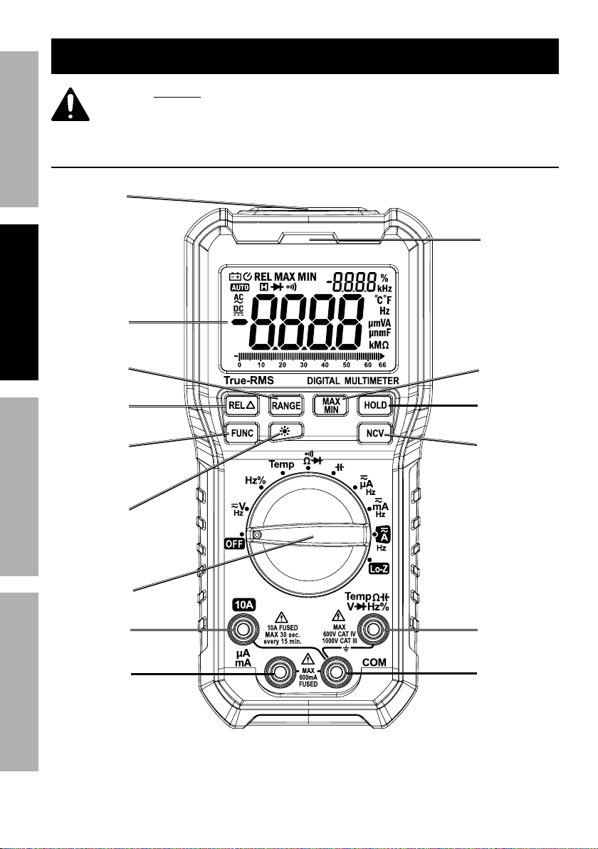
?*$'/%K%U*2&(*%F#*-
?@<6AT VX6;@ACVE D@CEA6E@EQ6?6AFX
<'84$"&8#
E&8KQ&8$,4$%
;,83*%U'$$&8
!,7'*%U'$$&8
% ;*,9%$.*%6EAC;6%CDXV;A@EA%?@<6AT%CE<V;D@ACVE%#*4$"&8%
,$%$.*%+*3"88"83%&2%$."#%5,8',7%"847'9"83%,77%$*Z$%'89*(%
#'+.*,9"83#%$.*(*"8%+*2&(*%#*$%'/%&(%'#*%&2%$."#%/(&9'4$1
!&7$,3*%
?*8#&(
W"#/7,>
;*7,$"Y*%
<'84$"&8%
U'$$&8
U,4[7"3.$%
U'$$&8
E&8KQ&8$,4$%
!&7$,3*%
C89"4,$&(
D@]%DCE%
U'$$&8
B&79%U'$$&8
E&8KQ&8$,4$%
!&7$,3*%U'$$&8
;&$,(>%?)"$4.
J^@%\,4[
M^^5@%\,4[
C8/'$%\,4[
QVD%\,4[
Page 6 <&(%$*4.8"4,7%H'*#$"&8#I%/7*,#*%4,77%JKLLLKLMMKNOPO1 Item 64019
Page 7
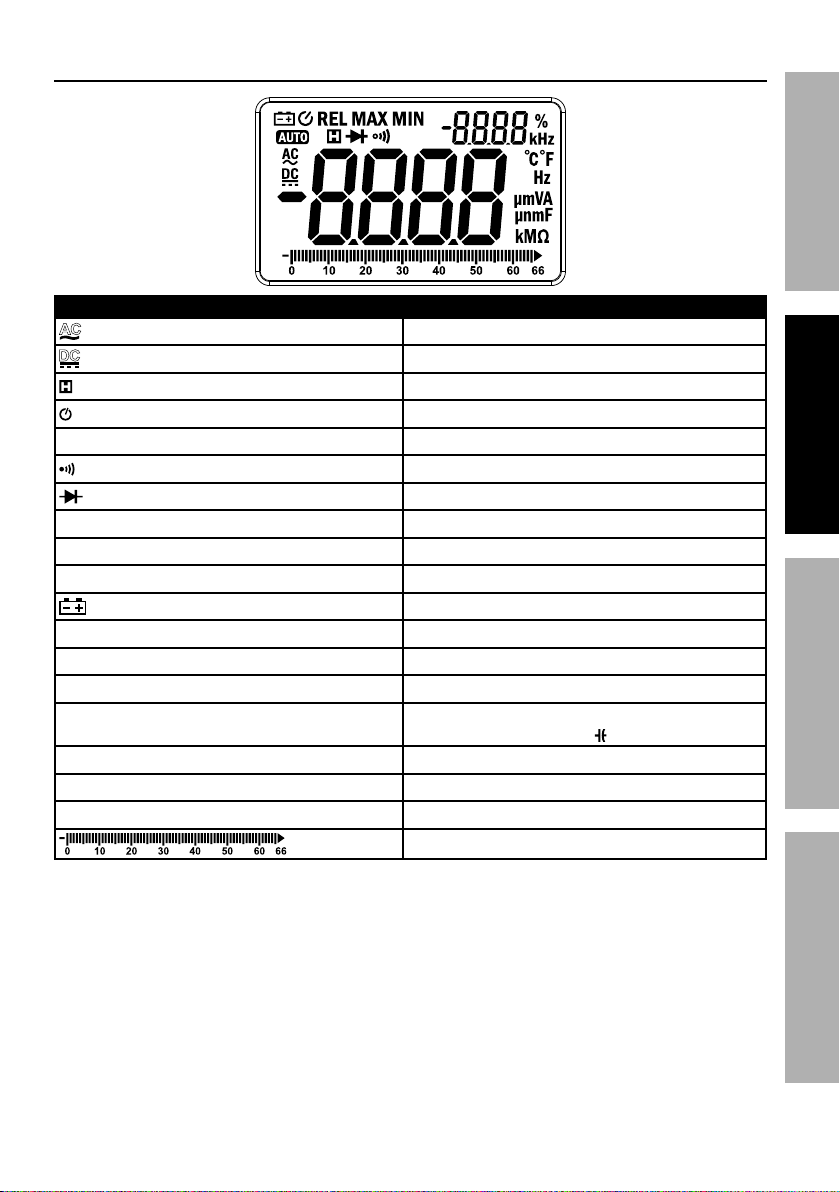
W"#/7,>
?>5+&7 W*#4("/$"&8
@Q
WQ
@FAV Auto range mode
;6G Relative measurement mode
D@] The maximum value is being measured
DCE The minimum value is being measured
_ Percent (Duty cycle)
`Q0`< Celsius/Fahrenheit
Ω, kΩ, MΩ Ohms, Kiloohms, Megaohms (Resistance)
nF, μF, mF
5!I%! Millivolts, Volts (Voltage)
@ Amperes (Current)
BaI%[Ba Hertz, Kilohertz (Frequency)
Alternating current
Direct current
Indicates that display data is being held
Auto Power-Off
Continuity
Diode test
Battery low
Nanofarad, Microfarad,
Millifarad (Capacitance )
Bar graph
?@<6ATVX6;@ACVED@CEA6E@EQ6 ?6AFX
Page 7<&(%$*4.8"4,7%H'*#$"&8#I%/7*,#*%4,77%JKLLLKLMMKNOPO1Item 64019
Page 8
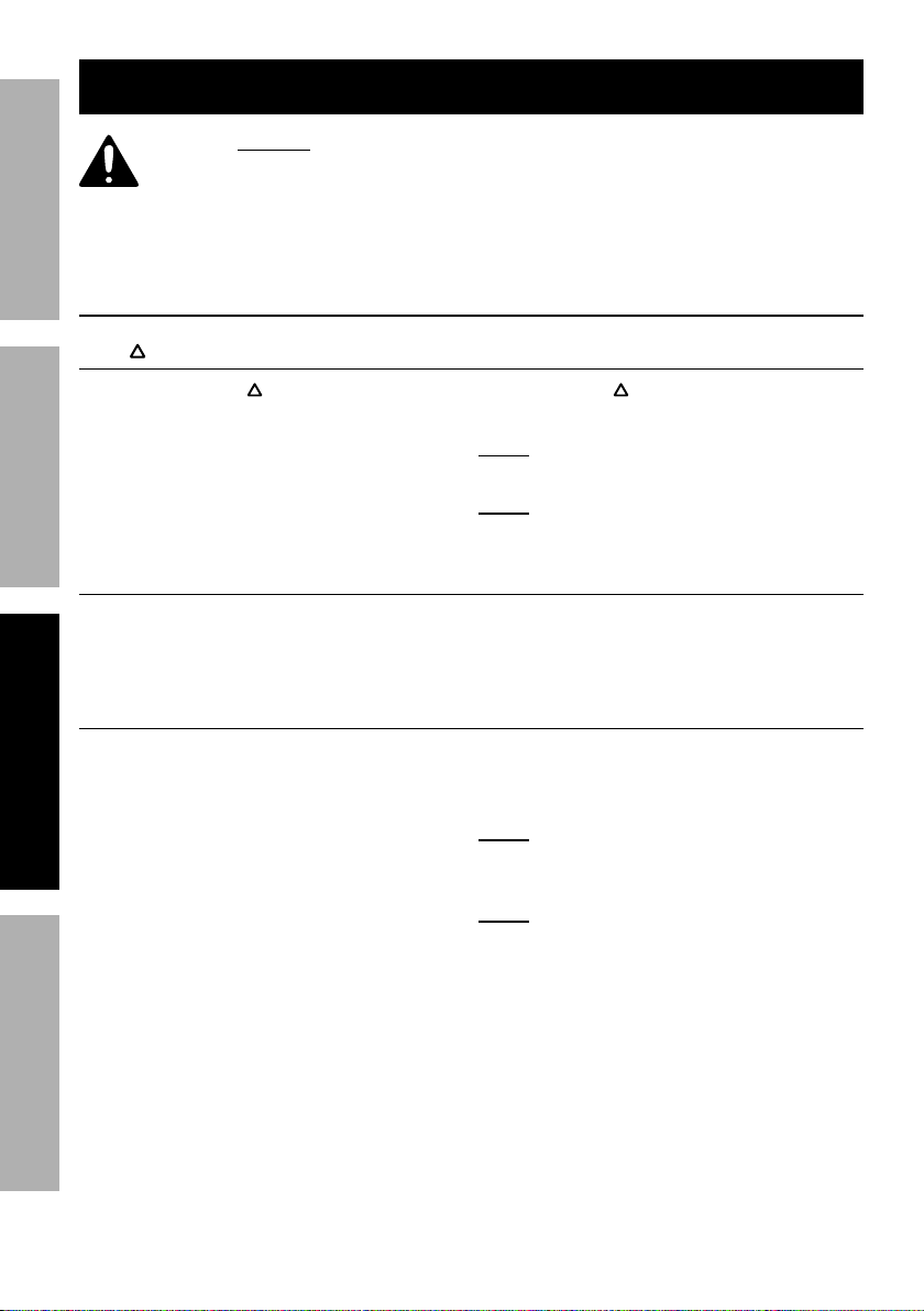
V/*(,$"83%C8#$('4$"&8#
?@<6AT VX6;@ACVE D@CEA6E@EQ6?6AFX
% ;*,9%$.*%6EAC;6%CDXV;A@EA%?@<6AT%CE<V;D@ACVE%#*4$"&8%
,$%$.*%+*3"88"83%&2%$."#%5,8',7%"847'9"83%,77%$*Z$%'89*(%
#'+.*,9"83#%$.*(*"8%+*2&(*%#*$%'/%&(%'#*%&2%$."#%/(&9'4$1
67*4$("4,7%#.&4[%4,8%4,'#*%9*,$.%&(%"8='(>b%E6!6;%AVFQB%
*Z/&#*9%4&89'4$&(#%&2%*7*4$("4"$>1
S*8*(,7%V/*(,$"83%C8#$('4$"&8#
REL
1. Press the ;6G button once to
enter relative measurement mode
and store a reference value.
2. Take additional measurements to
display difference between measured
value and reference value.
D,8',7%;,83*
The Meter’s default range is @FAV%in voltage, current, resistance, and
capacitance modes. To select manual range, press ;@ES6. Each press of the
button increases the range. Hold the ;@ES6 button to return to auto-range.
D,Z"5'5%,89%D"8"5'5%!,7'*%D*,#'(*5*8$#
1. Press the D@]%DCE button one
time to measure the maximum
value at any range.
2. Press the D@]%DCE button
two times to measure the
minimum value at any range.
3. Read measured minimum or maximum
value at the top right of the Display.
3. Press ;6G button a second time to
return to normal measuring mode.
E&$*- Relative measurement mode can
only be used in manual range mode.
E&$*- Relative measurement mode
cannot be used in Ba_ mode.
4. Hold the D@]%DCE button
for one or more seconds to
return to normal mode.
E&$*- The Meter is automatically set to
manual range mode when measuring
minimum or maximum value.
E&$*- Minimum and maximum value mode
cannot be used while in Ba_ mode.
Page 8 <&(%$*4.8"4,7%H'*#$"&8#I%/7*,#*%4,77%JKLLLKLMMKNOPO1 Item 64019
Page 9

W,$,%B&79
The data hold function keeps the current reading on the Display. To activate data hold:
1. Press the BVGW button and
the reading will be held on the
Display. The %symbol appears.
2. Press BVGW again to release the hold.
U,4[7"3.$
1. Press the button to turn on the
Display backlight for 60 seconds.
2. Press the button a second time
to turn the Display backlight off.
E&$*- Frequent use of the backlight
shortens the life of the batteries. Only
use the backlight when necessary.
EQ!%cE&8KQ&8$,4$%!&7$,3*d
1. Turn Rotary Switch to any position.
2. Hold the EQ! button and move the
Non-Contact Voltage Sensor close to
the unshielded conductor. If detected
voltage is >110V AC, Meter will beep
and the Non-Contact Voltage Indicator
will flash.
R@;ECESb 6Y*8%"2%8&%"89"4,$"&8%"#%
3"Y*8I%Y&7$,3*%5,>%#$"77%+*%/(*#*8$1
Do not rely solely on NCV detection to
determine the presence of voltage.
@'$&%X&)*(KV22
If the Meter is not used for approximately 15 minutes, it automatically turns itself off
to conserve battery power. To turn the Meter back on after auto-off, press any button.
To disable Auto Power-Off, hold the <FEQ button while powering the Meter on.
U,(%S(,/.
The bar graph updates 10 times faster than the digital display. This can
be used for monitoring changes in measurements at a higher sampling
rate. The bar graph indicates polarity (K) and overload ( ).
?@<6ATVX6;@ACVED@CEA6E@EQ6 ?6AFX
Page 9<&(%$*4.8"4,7%H'*#$"&8#I%/7*,#*%4,77%JKLLLKLMMKNOPO1Item 64019
Page 10

D*,#'(*5*8$%V/*(,$"&8
E&$*- Remove plugs from
ends of Test Leads (included)
before connecting to Meter.
?@<6AT VX6;@ACVE D@CEA6E@EQ6?6AFX
@Q0WQ%!&7$,3*%D*,#'(*5*8$
Measure AC conductors carrying
up to 1000 VAC, 40-400 Hz.
Measure DC conductors
carrying up to 1000 VDC.
R@;ECESb Use caution when working
near voltages above 30 VAC rms,
42 VAC peak, or 60 VDC. Voltages this
high present a risk of electric shock.
1. Plug black test lead into QVD Jack.
Plug red test lead into C8/'$ Jack.
2. Turn Rotary Switch to the %position.
3. Press <FEQ button to choose
between AC and DC voltage.
<(*H'*84>0W'$>%Q>47*%D*,#'(*5*8$
Measure frequency up to 66MHz.
1. Plug black test lead into QVD Jack.
Plug red test lead into C8/'$ Jack.
2. Turn the Rotary Switch to
the Ba_%position.
3. Connect the Test Leads across
the circuit to be measured.
E&$*- Test Lead probes have removable
covers for overvoltage protection. With
covers in place, Test Leads are rated for
use with CAT IV circuits. Exposed probes
are rated for use with CAT II circuits.
4. Carefully touch exposed
conductors with tips of probes.
5. Read measured voltage on the
Display. For AC voltage, frequency
is shown at the top right.
• Use the G&Ke switch position on
Meter when readings are suspect
(ghost or stray voltages may
be present), or when testing for
the presence of voltage. Follow
instructions for fG&)%C5/*9,84*%
D*,#'(*5*8$g%&8%/,3*%Jh1
6. When testing is complete, turn
Rotary Switch to V<<, remove
Test Leads and store with Meter.
4. Read measured frequency in
the center of the Display. Duty
cycle is shown at the top right.
5. When testing is complete, turn
Rotary Switch to V<<I remove
Test Leads%and store with Meter.
Page 10 <&(%$*4.8"4,7%H'*#$"&8#I%/7*,#*%4,77%JKLLLKLMMKNOPO1 Item 64019
Page 11
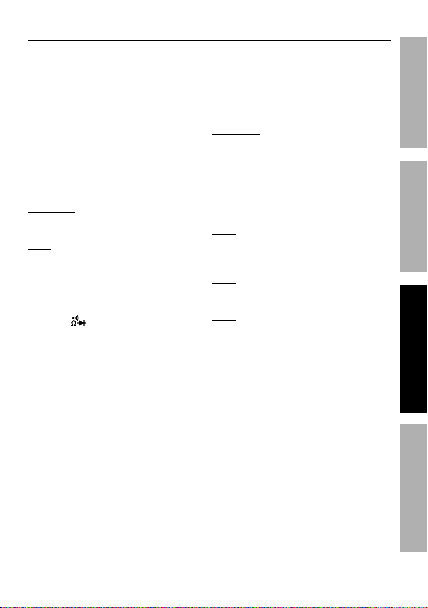
A*5/*(,$'(*%D*,#'(*5*8$
Measure temperature from 32°F
to 1832°F (0°C to 1000°C).
1. Connect red end of Thermocouple
(included) to the C8/'$ Jack and
the black end to the QVD Jack.
2. Turn Rotary Switch to the A*5/
position. The Display will show the
current ambient temperature.
;*#"#$,84*%D*,#'(*5*8$
Measure circuit resistance up to 66M Ohms.
R@;ECESb To prevent electric shock, turn
off all power and fully discharge capacitors
on the circuit under test before measuring.
E&$*- When measuring Ohms,
start with the lowest range if the
resistance is unknown.
1. Plug black test lead into QVD Jack.
Plug red test lead into C8/'$ Jack.
2. Turn the Rotary Switch
to the position.
3. Carefully touch exposed
conductors with tips of probes.
4. Read measured resistance
on the Display.
3. Press <FEQ to switch between
Celsius and Fahrenheit.
4. Touch the tip of the Thermocouple
to the object to be tested.
5. Read measured temperature
on the Display.
R@;ECESb A&%/(*Y*8$%*7*4$("4%
#.&4[I%(*5&Y*%A.*(5&4&'/7*%+*2&(*%
#)"$4."83%+*$)**8%$*#$"83%5&9*#1
5. When testing is complete, turn
Rotary Switch to V<<, remove
Test Leads and store with Meter.
E&$*- Sometimes the resistor value and
measured resistance differ. This is due
to the Meter’s output test current going
through all possible paths between leads.
E&$*- For resistance measurements
above 1MΩ, allow a few seconds
to get a steady reading.
E&$*- When leads are disconnected
or measurement is out of
range, VG is displayed.
?@<6ATVX6;@ACVED@CEA6E@EQ6 ?6AFX
Page 11<&(%$*4.8"4,7%H'*#$"&8#I%/7*,#*%4,77%JKLLLKLMMKNOPO1Item 64019
Page 12
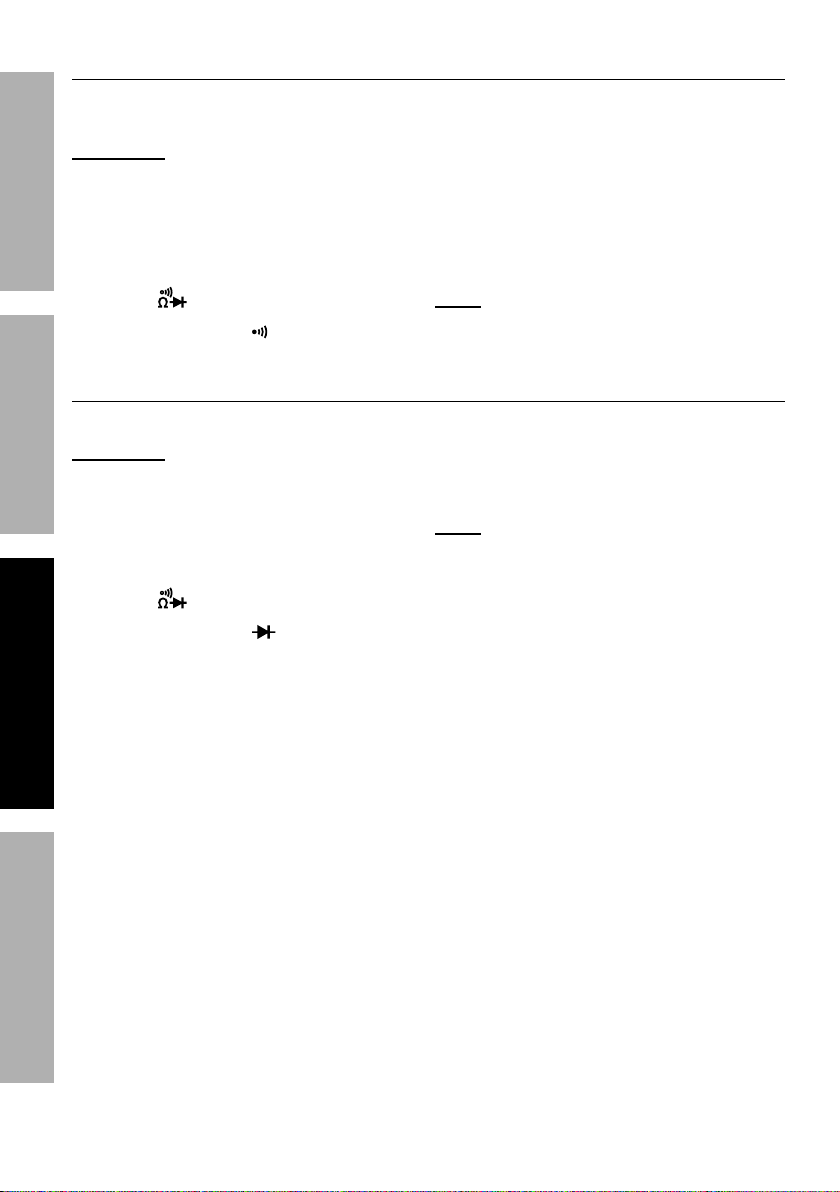
Q&8$"8'"$>%D*,#'(*5*8$
Test continuity between two
points of a circuit.
?@<6AT VX6;@ACVE D@CEA6E@EQ6?6AFX
R@;ECESb To prevent electric shock, turn
off all power and fully discharge capacitors
on the circuit under test before measuring.
1. Plug black test lead into QVD Jack.
Plug red test lead into C8/'$ Jack.
2. Turn the Rotary Switch
to the position.
3. Press <FEQ until is displayed.
W"&9*%D*,#'(*5*8$
Test voltage drop in diodes.
R@;ECESb To prevent electric shock, turn
off all power and fully discharge capacitors
on the circuit under test before measuring.
1. Plug black test lead into QVD Jack.
Plug red test lead into C8/'$ Jack.
2. Turn the Rotary Switch
to the %position.
3. Press <FEQ%until is displayed.
4. Connect the test leads across
the circuit to be measured.
5. Read measured resistance on the
Display. If the measured resistance
is less than 50Ω, Meter will beep.
6. When testing is complete, turn
Rotary Switch to V<<, remove
Test Leads and store with Meter.
E&$*- If Test Leads are open or
the resistance of the circuit is out
of range, VG is displayed.
4. Connect red probe to diode’s anode
and black probe to its cathode.
5. Read measured forward-biased
voltage drop on the Display.
E&$*- If the test leads are reversed
or open, VG is displayed.
6. When testing is complete, turn
Rotary Switch to V<<, remove
Test Leads and store with Meter.
Page 12 <&(%$*4.8"4,7%H'*#$"&8#I%/7*,#*%4,77%JKLLLKLMMKNOPO1 Item 64019
Page 13

Q,/,4"$,84*%D*,#'(*5*8$#
Measure capacitance up to 66mF.
R@;ECESb Turn off all power and fully
discharge capacitors on the circuit
under test before measuring.
1. Plug black test lead into QVD Jack.
Plug red test lead into C8/'$ Jack.
2. Turn the Rotary Switch
to the position.
Q'((*8$%D*,#'(*5*8$
Measure AC and DC conductors
carrying up to 10 amperes.
E&$*- Amperage is always tested
in series with circuit under test.
E&$*- When using manual range
mode, always start with the highest
range if the amperage is unknown.
1. Turn the Rotary Switch to the
, or position, depending on the
amperage of the conductor under test.
2. Always start with the highest range
if the amperage is unknown.
3. Plug black test lead into QVD
Jack. If amperage is < 600mA,
plug red test lead into μAmA Jack.
If amperage is > 600mA, plug
red test lead into J^@ Jack.
3. Carefully touch capacitor
leads with tips of probes.
4. Read measured capacitance
on the Display.
5. When testing is complete, turn
Rotary Switch to V<<, remove
and store capacitor and Meter.
4. Connect the Test Leads across
the circuit to be measured.
5. Read measurement. For AC current,
frequency is shown at the top right.
Switch to lower ranges, as necessary,
to get the most accurate reading.
6. When testing is complete, turn
Rotary Switch to V<<, remove
Test Leads and store with Meter.
E&$*- If the Display shows VG while in
manual range mode, the measurement
has exceeded the selected range. A
higher range should be selected.
?@<6ATVX6;@ACVED@CEA6E@EQ6 ?6AFX
Page 13<&(%$*4.8"4,7%H'*#$"&8#I%/7*,#*%4,77%JKLLLKLMMKNOPO1Item 64019
Page 14

G&)%C5/*9,84*%D*,#'(*5*8$
Eliminate ghost voltages.
1. Plug black Test Lead into
?@<6AT VX6;@ACVE D@CEA6E@EQ6?6AFX
black QVD Jack. Plug red
Test Lead into C8/'$ Jack.
2. Turn Rotary Switch to G&Ke position.
3. Carefully touch exposed
conductors with tips of probes.
4. Read measurement.
5. When testing is complete, turn
Rotary Switch to V<<I remove
Test Leads and store with Meter.
Page 14 <&(%$*4.8"4,7%H'*#$"&8#I%/7*,#*%4,77%JKLLLKLMMKNOPO1 Item 64019
Page 15
D,"8$*8,84*%,89%?*(Y"4"83
%X(&4*9'(*#%8&$%#/*4"2"4,77>%*Z/7,"8*9%"8%$."#%5,8',7%
5'#$%+*%/*(2&(5*9%&87>%+>%,%H',7"2"*9%$*4.8"4",81
Q7*,8"83I%D,"8$*8,84*I%,89%G'+("4,$"&8
1. Wipe unit with a dry, lint-free cloth.
Do not use solvents or abrasives.
2. Remove battery if not in
use for long periods.
3. Store unit in a dry location.
4. Other than the battery and fuses,
there are no replaceable parts on
this unit. ;*/,"(#%#.&'79%+*%9&8*%
+>%,%H',7"2"*9%$*4.8"4",81
U,$$*(>0<'#*%;*/7,4*5*8$
If the sign appears on the Display,
the battery should be replaced.
1. Remove Test Leads from the Meter.
2. Turn the unit over.
3. Replace battery.
a. Remove screw on battery cover.
b. Remove battery cover carefully.
c. Pull batteries out of unit and
replace with the same.
E&$*- Do not reverse the
polarity of the battey.
4. Replace fuse.
a. Remove screw on battery cover.
b. Remove battery cover carefully.
c. Remove screw on fuse cover.
d. Remove fuse cover carefully.
e. Pull fuse(s) out and replace
with new fuse(s) of the
same type and rating.
5. Replace cover(s) and
retighten screw(s).
Q,7"+(,$"&8
Have the Meter calibrated by a qualified technician every year.
?@<6ATVX6;@ACVED@CEA6E@EQ6 ?6AFX
Page 15<&(%$*4.8"4,7%H'*#$"&8#I%/7*,#*%4,77%JKLLLKLMMKNOPO1Item 64019
Page 16

G"5"$*9%P^%W,>%R,((,8$>
Harbor Freight Tools Co. makes every effort to assure that its products meet high quality
and durability standards, and warrants to the original purchaser that this product is free from
defects in materials and workmanship for the period of 90 days from the date of purchase.
This warranty does not apply to damage due directly or indirectly, to misuse, abuse, negligence
or accidents, repairs or alterations outside our facilities, criminal activity, improper installation,
normal wear and tear, or to lack of maintenance. We shall in no event be liable for death,
injuries to persons or property, or for incidental, contingent, special or consequential damages
arising from the use of our product. Some states do not allow the exclusion or limitation of
incidental or consequential damages, so the above limitation of exclusion may not apply to you.
THIS WARRANTY IS EXPRESSLY IN LIEU OF ALL OTHER WARRANTIES, EXPRESS OR
IMPLIED, INCLUDING THE WARRANTIES OF MERCHANTABILITY AND FITNESS.
To take advantage of this warranty, the product or part must be returned to us with transportation
charges prepaid. Proof of purchase date and an explanation of the complaint must accompany
the merchandise. If our inspection verifies the defect, we will either repair or replace
the product at our election or we may elect to refund the purchase price if we cannot readily
and quickly provide you with a replacement. We will return repaired products at our expense,
but if we determine there is no defect, or that the defect resulted from causes not within
the scope of our warranty, then you must bear the cost of returning the product.
This warranty gives you specific legal rights and you may also
have other rights which vary from state to state.
;*4&(9%?*(",7%E'5+*(%B*(*-%
%
E&$*- If product has no serial number,
record month and year of purchase instead.
ihPJ%D"##"&8%V,[#%U7Y91%%j%%XV%U&Z%M^^P%%j%%Q,5,("77&I%Q@%Pi^JJ%%j%%JKLLLKLMMKNOPO
 Loading...