

Page 1

10/100BASE-TX to 100BASE-FX
Fast Ethernet
Media Converter
Quick Installation Guide
Page 2
FCC Class B Certification
This equipment has been tested and found to comply with
the regulations for a Class B digital device, pursuant to Part
15 of the FCC Rules. These limits are designed to provide
reasonable protection against harmful interference when the
equipment is operated in a commercial environment. This
equipment generates, uses, and can radiate radio frequency
energy and, if not installed and used in accordance with this
user’s guide, may cause harmful interference to radio
communications. Operation of this equipment in a
residential area is likely to cause harmful interference, in
which case the user will be required to correct the
interference at his own expense.
CE Mark Warning
This is a Class B product. In a domestic environment, this
product may cause radio interference, in which case the user
may be required to take adequate measures.
VCCI Class B Compliance (Japan)
This is a product of VCCI Class B Compliance
2
Page 3

Introduction
Thank you for choosing the 10/100BASE Fast Ethernet
Media Converter, The Converter introduced here
provides one channel media conversion between
10/100BASE-TX and 100BASE-FX.
About Media Converter
The Media Converter is a network technology specified
by IEEE 802.3 10BASE-T, IEEE802.3u 100BASE-TX,
100BASE-FX standards.
3
Page 4

Product Features
9 One-channel media conversion between
10/100BASE-TX and 100BASE-FX
9 Fiber media allows: multi-mode fiber using SC,
LC or MT-RJ connector; single-mode fiber using
SC connector
9 Auto negotiation of speed and duplex mode on TX
port
9 Auto MDI-X on TX port
9 One slide switch for configuring fixed half/full
duplex modes
9 Store-and-forward mechanism
9 Back-pressure & IEEE802.3x compliant flow
control
9 Full wire-speed forwarding rate
9 Front panel status LEDs
9 Used as a stand-alone device or with a chassis
9 Hot-swappable when used with a chassis
4
Page 5

Installation
This chapter gives step-by-step installation instructions
for the Converter.
Selecting a Site for the Equipment
As with any electric device, you should place the
equipment where it will not be subjected to extreme
temperatures, humidity, or electromagnetic interference.
Specifically, the site you select should meet the
following requirements:
1. The ambient temperature should be between 32
and 104 degrees Fahrenheit (0 to 40 degrees
Celsius).
2. The relative humidity should be less than 90
percent, non-condensing.
3. Surrounding electrical devices should not exceed
the electromagnetic field (RFC) standards for
IEC 801-3, Level 2 (3V/M) field strength.
4. Make sure that the equipment receives adequate
ventilation. Do not block the ventilation holes on
each side of the switch or the fan exhaust port on
the side or rear of the equipment.
5. The power outlet should be within 1.8 meters of
the switch.
5
Page 6
Connecting to Power
1. This Converter is a plug-and-play device.
2. Connect the supplied AC to DC power adaptor
with a power voltage of 7.5Vdc/1.5Amp to the
receptacle on the rear panel of the converter, and
then attach the plug into a standard AC outlet
with a voltage range from 100 to 260 Vac.
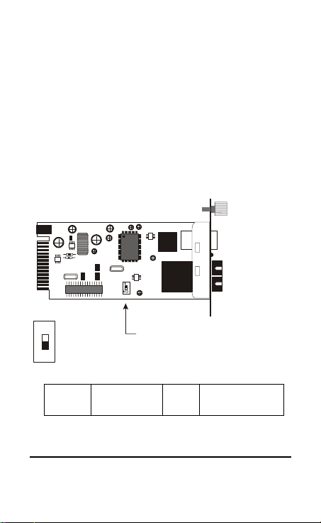
Sliding Switch
There is a sliding switch for duplex mode setting for
fiber port. Refer to the table below for more details.
ON
Switch 1 : On -> Fiber Half Duplex
Off -> Fiber Full Duplex
1
On Half Duplex Off
Full Duplex
(default)
6
Page 7
Installing in a Chassis
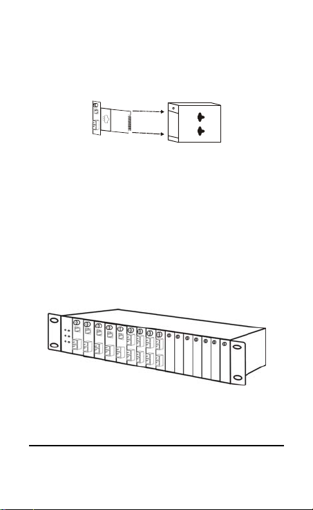
The Converter can be fit into any of the expansion slots
on a special designed chassis.
Unscrew and pull out the
media converter board
y First, install the converter onto a carrier supplied with
the chassis:
Step 1- Unscrew the carrier from the desired
Step 2- Remove the screw on the converter as shown
Step 3- Fit the converter onto the carrier and use the
expansion slot on the chassis.
below.
screw to secure it.
7
Page 8
LED Indicator
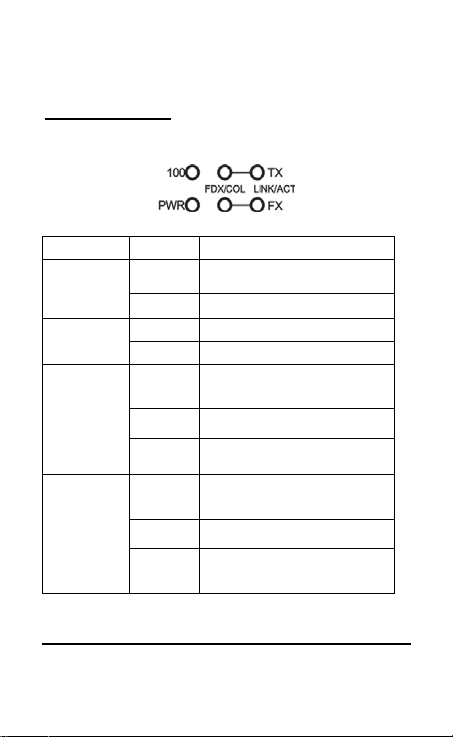
The LED indicators give you instant feedback on status
of the converter:
LEDs State Indication
(PWR)
(100)
TX Port (TX)
FX Port (FX)
FDX/COL
TX Port (TX)
FX Port (FX)
LINK/ACT
Steady Power on Power
Off Power off
Steady Runs at 100Mbps on TX port 100 Mbps
Off Runs at 10Mbps on TX port
Steady
(FDX)
Lights off Connection in half duplex mode
Blinking
(COL)
Steady
(LINK)
Lights off Not Linking
Blinking
(ACT)
Connection in full duplex mode
FDX stands for FULL-DUPLEX
Data collision
A valid network connection established
Transmitting or receiving data
ACT stands for Activity
8
Page 9
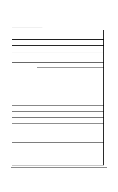
Specifications
Applicable
Standards
Fixed Ports
Speed
Forwarding
rate
LED Indicators
Cable
Dimensions
Weight
Power
Power
Consumption
Operating
Temperature
Storage
Temperature
Humidity
Emissions
IEEE 802.3 10BASE-T
IEEE802.3u 100BASE-TX & 100BASE-FX
1 TX port, 1 FX port
10/20Mbps for half/full-duplex
100/200Mbps for half/full-duplex
148,800pps
Per Unit- (2 LEDs): Power; Speed( 100 )
Per Port- (2 LEDs): FDX/COL, LINK/ACT
10BASE-T –
2-pair UTP Cat. 3,4,5, up to 100 m (328 ft)
100BASE-TX --
2-pair UTP Cat. 5, up to 100 m (328 ft)
100BASE-FX --
62.5/125μm multi-mode fiber optic cable, up to
2 km
10/125μm single-mode fiber optic cable, up to
75 km
L120 × W88 × H25 mm
305 g
External power adaptor 7.5V 1.5A
7.2W Max.
0°C ~ 40°C (32°F ~ 104°F)
-25°C ~ 70°C (-13°F ~ 158°F)
10 ~ 90%, non-condensing
FCC part 15 Class B, CISPR ClassB, VCCI
Class B, CE Mark
9
Page 10
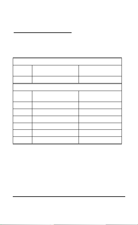
Ordering Information
Please include the following information when ordering:
Fiber type: multi-mode or single-mode
Fiber connector type: SC, LC or MT-RJ
Segment distance range for the fiber port
TX port
Connector
Type
RJ-45 Copper Wire Max. 100 m
FX port
Connector
Type
SC Multi-Mode Fiber Max. 2 km
MT-RJ Multi-Mode Fiber Max. 2 km
LC Multi-Mode Fiber Max. 2 km
SC Single-Mode Fiber Max. 15 km
SC Single-Mode Fiber Max. 40 km
SC Single-Mode Fiber Max. 60 km
P/N:2907M110SC25000
Rev:B1-03
Cabling Segment Distance
Cabling Segment Distance
10
 Loading...