

Page 1

Clavister cOS Core
Administration Guide
Version: 10.20.02
Clavister AB
SE-89160 Örnsköldsvik
Phone: +46-660-299200
Published 2014-03-31
Copyright © 2014 Clavister AB
Sjögatan 6J
SWEDEN
www.clavister.com
Page 2

Clavister cOS Core
Administration Guide
Version: 10.20.02
Published 2014-03-31
Copyright © 2014 Clavister AB
Copyright Notice
This publication, including all photographs, illustrations and software, is protected under
international copyright laws, with all rights reserved. Neither this manual, nor any of the material
contained herein, may be reproduced without the written consent of Clavister.
Disclaimer
The information in this document is subject to change without notice. Clavister makes no
representations or warranties with respect to the contents hereof and specifically disclaims any
implied warranties of merchantability or fitness for a particular purpose. Clavister reserves the
right to revise this publication and to make changes from time to time in the content hereof
without any obligation to notify any person or parties of such revision or changes.
Limitations of Liability
UNDER NO CIRCUMSTANCES SHALL CLAVISTER OR ITS SUPPLIERS BE LIABLE FOR DAMAGES OF
ANY CHARACTER (E.G. DAMAGES FOR LOSS OF PROFIT, SOFTWARE RESTORATION, WORK
STOPPAGE, LOSS OF SAVED DATA OR ANY OTHER COMMERCIAL DAMAGES OR LOSSES)
RESULTING FROM THE APPLICATION OR IMPROPER USE OF THE CLAVISTER PRODUCT OR
FAILURE OF THE PRODUCT, EVEN IF CLAVISTER IS INFORMED OF THE POSSIBILITY OF SUCH
DAMAGES. FURTHERMORE, CLAVISTER WILL NOT BE LIABLE FOR THIRD-PARTY CLAIMS AGAINST
CUSTOMER FOR LOSSES OR DAMAGES. CLAVISTER WILL IN NO EVENT BE LIABLE FOR ANY
DAMAGES IN EXCESS OF THE AMOUNT CLAVISTER RECEIVED FROM THE END-USER FOR THE
PRODUCT.
2
Page 3

Table of Contents
Preface ... ... .... .. .. . .. . ... ... ... ... ... ... ... .... .. .. . ... ... ... ... ... ... ... .... .. .. . ... ... ... ... ... ... ... .... .. .. . ... 14
1. cOS Core Overview . . .. . .. . ... ... ... ... ... ... ... .... .. .. . ... ... ... ... ... ... ... .... .. .. . ... ... ... ... ... ... ... .. 17
1.1. Features ... .. .. . .. . ... ... ... ... ... ... ... .... .. .. . ... ... ... ... ... ... ... .... .. .. . ... ... ... ... ... ... ... ... 17
1.2. cOS Core Architecture . ... ... ... ... ... ... ... .... .. .. . ... ... ... ... ... ... ... .... .. .. . ... ... ... ... ... .22
1.2.1. State-based Architecture . .. .. . .. . ... ... ... ... ... ... ... .... .. .. . ... ... ... ... ... ... ... .. 22
1.2.2. cOS Core Building Blocks .. .. ... ... ... ... ... ... ... .... .. .. . .. . ... ... ... ... ... ... .... .. .22
1.2.3. Basic Packet Flow ... . .. . .. . ... ... ... ... ... ... ... .... .. .. . ... ... ... ... ... ... ... .... .. .. . .. . 23
1.3. cOS Core State Engine Packet Flow .. ... ... ... ... ... .... .. .. . ... ... ... ... ... ... ... .... .. .. . ... 26
2. Management and Maintenance ... ... ... ... ... ... ... .... .. .. . ... ... ... ... ... ... ... .... .. .. . ... ... ... ... .. 31
2.1. Managing cOS Core .. .. .. . ... ... ... ... ... ... ... .... .. .. . ... ... ... ... ... ... ... .... .. .. . ... ... ... ... .31
2.1.1. Overview .. .. ... ... ... ... ... .... .. .. . ... ... ... ... ... ... ... .... .. .. . ... ... ... ... ... ... ... .... . 31
2.1.2. Default Administrator Accounts .. ... ... .... .. .. . ... ... ... ... ... ... ... .... .. .. . ... ... 33
2.1.3. The Web Interface ... ... .... .. .. . .. . ... ... ... ... ... ... .... .. .. . .. . ... ... ... ... ... ... ... ... 33
2.1.4. The CLI . ... ... ... ... ... .... .. .. . .. . ... ... ... ... ... ... .... .. .. . .. . ... ... ... ... ... ... ... .... .. .. 39
2.1.5. CLI Scripts .. .. .. . .. . ... ... ... ... ... ... ... .... .. .. . ... ... ... ... ... ... ... .... .. .. . ... ... ... ... .50
2.1.6. Secure Copy .. . ... ... ... ... ... ... ... .... .. .. . ... ... ... ... ... ... ... .... .. .. . ... ... ... ... ... .. 55
2.1.7. The Console Boot Menu ... ... ... ... .... .. .. . ... ... ... ... ... ... ... .... .. .. . ... ... ... ... .57
2.1.8. Changing Management Access .. . .. . .. . .. . ... ... ... ... ... ... .... .. .. . .. . ... ... ... ... 60
2.1.9. Management Advanced Settings .. .... .. .. . ... ... ... ... ... ... ... .... .. .. . .. . ... ... .65
2.1.10. Working with Configurations .. .. ... ... ... ... ... .... .. .. . ... ... ... ... ... ... ... .... .. 66
2.2. Events and Logging . ... ... .... .. .. . ... ... ... ... ... ... ... .... .. .. . .. . ... ... ... ... ... ... .... .. .. . .. . .73
2.2.1. Overview .. .. ... ... ... ... ... .... .. .. . ... ... ... ... ... ... ... .... .. .. . ... ... ... ... ... ... ... .... . 73
2.2.2. Log Messages .. ... ... ... ... .... .. .. . ... ... ... ... ... ... ... .... .. .. . ... ... ... ... ... ... ... ... 73
2.2.3. Creating Log Receivers .. ... ... ... ... .... .. .. . ... ... ... ... ... ... ... .... .. .. . ... ... ... ... 74
2.2.4. Logging to MemoryLogReceiver . .. ... ... ... ... ... .... .. .. . ... ... ... ... ... ... ... .... 75
2.2.5. Logging to Syslog Hosts .. .. .. . ... ... ... ... ... ... ... .... .. .. . ... ... ... ... ... ... ... .... . 75
2.2.6. Logging to the Clavister Logger .... ... ... ... ... ... .... .. .. . ... ... ... ... ... ... ... .... 77
2.2.7. Severity Filter and Message Exceptions .. .. ... ... ... ... ... .... .. .. . ... ... ... ... ... 78
2.2.8. SNMP Traps . ... ... ... ... ... ... ... .... .. .. . ... ... ... ... ... ... ... .... .. .. . ... ... ... ... ... ... .79
2.2.9. Advanced Log Settings .. ... .... .. .. . ... ... ... ... ... ... ... .... .. .. . ... ... ... ... ... ... ... 80
2.3. RADIUS Accounting ... .... .. .. . ... ... ... ... ... ... ... .... .. .. . ... ... ... ... ... ... ... .... .. .. . ... ... .. 82
2.3.1. Overview .. .. ... ... ... ... ... .... .. .. . ... ... ... ... ... ... ... .... .. .. . ... ... ... ... ... ... ... .... . 82
2.3.2. RADIUS Accounting Messages .. ... .... .. .. . ... ... ... ... ... ... ... .... .. .. . ... ... ... .. 82
2.3.3. Interim Accounting Messages ... ... ... ... .... .. .. . ... ... ... ... ... ... ... .... .. .. . .. . .. 84
2.3.4. Configuring RADIUS Accounting .. .. . .. . ... ... ... ... ... ... .... .. .. . .. . ... ... ... ... .. 84
2.3.5. RADIUS Accounting Security .. ... ... ... ... ... .... .. .. . ... ... ... ... ... ... ... .... .. .. . .86
2.3.6. RADIUS Accounting and High Availability .. .... .. .. . .. . ... ... ... ... ... ... ... .... . 86
2.3.7. Handling Unresponsive RADIUS Servers . ... ... ... ... ... ... ... .... .. .. . ... ... ... .. 86
2.3.8. Accounting and System Shutdowns ... ... ... ... .... .. .. . ... ... ... ... ... ... ... .... . 87
2.3.9. Limitations with NAT . ... ... ... .... .. .. . ... ... ... ... ... ... ... .... .. .. . ... ... ... ... ... ... .87
2.3.10. Advanced RADIUS Settings ... ... ... .... .. .. . ... ... ... ... ... ... ... .... .. .. . ... ... ... .87
2.4. Monitoring . .. ... ... ... ... ... .... .. .. . ... ... ... ... ... ... ... .... .. .. . ... ... ... ... ... ... ... .... .. .. . ... .. 89
2.4.1. Real-time Monitoring Counters .. ... ... ... ... ... .... .. .. . ... ... ... ... ... ... ... .... .. .89
2.4.2. Real-time Monitor Alerts .. .. ... ... ... ... ... ... .... .. .. . .. . ... ... ... ... ... ... ... .... .. .. 94
2.4.3. The Link Monitor ... ... .... .. .. . ... ... ... ... ... ... ... .... .. .. . ... ... ... ... ... ... ... .... .. .94
2.4.4. SNMP Monitoring . .. ... ... ... ... ... ... .... .. .. . ... ... ... ... ... ... ... .... .. .. . .. . ... ... ... 98
2.4.5. Hardware Monitoring .. ... ... .... .. .. . ... ... ... ... ... ... ... .... .. .. . ... ... ... ... ... ... 101
2.4.6. Memory Monitoring Settings . . .. . .. . ... ... ... ... ... ... ... .... .. .. . ... ... ... ... ... .. 105
2.5. Diagnostic Tools . .. . ... ... ... ... ... ... ... .... .. .. . ... ... ... ... ... ... ... .... .. .. . ... ... ... ... ... ... 106
2.5.1. Overview .. .. ... ... ... ... ... .... .. .. . ... ... ... ... ... ... ... .... .. .. . ... ... ... ... ... ... ... ... 106
2.5.2. Diagnostic CLI Commands ... .. ... ... ... ... ... ... ... .... .. .. . ... ... ... ... ... ... ... .. 106
2.5.3. The pcapdump CLI Command ... ... ... ... ... ... .... .. .. . ... ... ... ... ... ... ... .... .. 107
2.5.4. Hardware Fault Troubleshooting .. ... ... .... .. .. . .. . ... ... ... ... ... ... ... .... .. .. . 109
2.6. Maintenance .. . .. . ... ... ... ... ... ... ... .... .. .. . ... ... ... ... ... ... ... .... .. .. . ... ... ... ... ... ... ... 112
2.6.1. Software Upgrades ... .. .. . ... ... ... ... ... ... ... .... .. .. . ... ... ... ... ... ... ... .... .. .. . 112
2.6.2. Auto-Update Mechanism . ... ... ... ... ... ... ... .... .. .. . ... ... ... ... ... ... ... .... .. .. 114
3
Page 4

Clavister cOS Core
2.6.3. Backing Up Configurations .. ... .... .. .. . ... ... ... ... ... ... ... .... .. .. . ... ... ... ... .. 115
2.6.4. Restore to Factory Defaults .... .. .. . ... ... ... ... ... ... ... .... .. .. . ... ... ... ... ... ... . 117
2.6.5. Listing and Adding Ethernet Interfaces . ... ... ... ... ... .... .. .. . .. . ... ... ... ... .. 119
2.7. Licensing ... .... .. .. . ... ... ... ... ... ... ... .... .. .. . .. . ... ... ... ... ... ... .... .. .. . .. . ... ... ... ... ... .. 121
3. Fundamentals . .. .. . ... ... ... ... ... ... .... .. .. . .. . ... ... ... ... ... ... ... .... .. .. . ... ... ... ... ... ... ... .... .. .. . 127
3.1. The Address Book .. ... ... ... ... ... .... .. .. . ... ... ... ... ... ... ... .... .. .. . ... ... ... ... ... ... ... ... 127
3.1.1. Overview .. .. ... ... ... ... ... .... .. .. . ... ... ... ... ... ... ... .... .. .. . ... ... ... ... ... ... ... ... 127
3.1.2. IP Addresses .. .. ... ... ... ... ... ... .... .. .. . ... ... ... ... ... ... ... .... .. .. . ... ... ... ... ... . 128
3.1.3. Ethernet Addresses .. .. . .. . ... ... ... ... ... ... .... .. .. . .. . ... ... ... ... ... ... ... .... .. .. . 130
3.1.4. Address Groups .. ... ... ... ... .... .. .. . ... ... ... ... ... ... ... .... .. .. . .. . ... ... ... ... ... .. 131
3.1.5. Auto-Generated Address Objects ... ... ... ... ... ... .... .. .. . ... ... ... ... ... ... ... . 132
3.1.6. Address Book Folders .... ... ... ... ... .... .. .. . ... ... ... ... ... ... ... .... .. .. . ... ... ... . 132
3.2. IPv6 Support . .. ... ... ... ... ... .... .. .. . ... ... ... ... ... ... ... .... .. .. . ... ... ... ... ... ... ... .... .. .. . 134
3.3. Services ... .. .. . .. . ... ... ... ... ... ... ... .... .. .. . ... ... ... ... ... ... ... .... .. .. . .. . ... ... ... ... ... ... .. 143
3.3.1. Overview .. .. ... ... ... ... ... .... .. .. . ... ... ... ... ... ... ... .... .. .. . ... ... ... ... ... ... ... ... 143
3.3.2. Creating Custom Services ... ... ... ... ... ... .... .. .. . ... ... ... ... ... ... ... .... .. .. . ... 145
3.3.3. ICMP Services .. .. ... ... ... ... ... ... .... .. .. . .. . ... ... ... ... ... ... .... .. .. . .. . ... ... ... ... 148
3.3.4. Custom IP Protocol Services .. .. .. . ... ... ... ... ... ... ... .... .. .. . ... ... ... ... ... ... . 149
3.3.5. Service Groups .. .... .. .. . ... ... ... ... ... ... ... .... .. .. . ... ... ... ... ... ... ... .... .. .. . ... 150
3.3.6. Custom Service Timeouts . . .. . .. . ... ... ... ... ... ... ... .... .. .. . ... ... ... ... ... ... ... . 151
3.4. Interfaces .. .. ... ... ... ... ... ... ... .... .. .. . ... ... ... ... ... ... ... .... .. .. . ... ... ... ... ... ... ... .... .. . 152
3.4.1. Overview .. .. ... ... ... ... ... .... .. .. . ... ... ... ... ... ... ... .... .. .. . ... ... ... ... ... ... ... ... 152
3.4.2. Ethernet Interfaces . .. . .. . ... ... ... ... ... ... ... .... .. .. . ... ... ... ... ... ... ... .... .. .. . .. 154
3.4.3. Link Aggregation .. . .. . .. . .. . ... ... ... ... ... ... .... .. .. . .. . ... ... ... ... ... ... ... .... .. .. 165
3.4.4. VLAN .. ... ... ... ... ... ... .... .. .. . ... ... ... ... ... ... ... .... .. .. . .. . ... ... ... ... ... ... .... .. . 168
3.4.5. PPPoE ... .. .. . .. . ... ... ... ... ... ... ... .... .. .. . ... ... ... ... ... ... ... .... .. .. . ... ... ... ... ... 171
3.4.6. GRE Tunnels ... . .. . .. . ... ... ... ... ... ... ... .... .. .. . ... ... ... ... ... ... ... .... .. .. . ... ... .. 174
3.4.7. Loopback Interfaces .... .. .. . .. . ... ... ... ... ... ... ... .... .. .. . ... ... ... ... ... ... ... .... 178
3.4.8. Interface Groups . .. .. . ... ... ... ... ... ... ... .... .. .. . ... ... ... ... ... ... ... .... .. .. . ... ... 182
3.5. ARP . ... ... .... .. .. . ... ... ... ... ... ... ... .... .. .. . ... ... ... ... ... ... ... .... .. .. . ... ... ... ... ... ... ... ... 184
3.5.1. Overview .. .. ... ... ... ... ... .... .. .. . ... ... ... ... ... ... ... .... .. .. . ... ... ... ... ... ... ... ... 184
3.5.2. The ARP Cache ... ... .... .. .. . .. . ... ... ... ... ... ... ... .... .. .. . ... ... ... ... ... ... ... .... . 184
3.5.3. ARP Publish . ... ... .... .. .. . ... ... ... ... ... ... ... .... .. .. . .. . ... ... ... ... ... ... .... .. .. . .. 186
3.5.4. Using ARP Advanced Settings .. . .. . .. . .. . ... ... ... ... ... ... .... .. .. . .. . ... ... ... ... 189
3.6. IP Rules and IP Policies .. . ... ... ... ... ... ... ... .... .. .. . ... ... ... ... ... ... ... .... .. .. . ... ... ... .. 191
3.6.1. Security Policies .. .. ... ... ... ... ... ... ... .... .. .. . ... ... ... ... ... ... ... .... .. .. . ... ... ... 191
3.6.2. IP Rule Set Evaluation .. .. . ... ... ... ... ... ... ... .... .. .. . ... ... ... ... ... ... ... .... .. .. . 194
3.6.3. IP Rule Actions .. . .. . ... ... ... ... ... ... ... .... .. .. . ... ... ... ... ... ... ... .... .. .. . ... ... .. 195
3.6.4. Multiple IP Rule Sets .. ... ... .... .. .. . .. . ... ... ... ... ... ... .... .. .. . .. . ... ... ... ... ... .. 197
3.6.5. IP Rule Set Folders . .. ... ... ... ... ... .... .. .. . ... ... ... ... ... ... ... .... .. .. . ... ... ... ... 199
3.6.6. Configuration Object Groups ... ... ... ... .... .. .. . ... ... ... ... ... ... ... .... .. .. . ... . 200
3.6.7. IP Policies .. .. .. . ... ... ... ... ... ... ... .... .. .. . .. . ... ... ... ... ... ... .... .. .. . .. . ... ... ... .. 204
3.6.8. Application Control . ... ... .... .. .. . ... ... ... ... ... ... ... .... .. .. . ... ... ... ... ... ... ... . 207
3.7. Schedules .. .. ... ... ... ... ... .... .. .. . ... ... ... ... ... ... ... .... .. .. . ... ... ... ... ... ... ... .... .. .. . ... 219
3.8. Certificates .. .... .. .. . ... ... ... ... ... ... ... .... .. .. . ... ... ... ... ... ... ... .... .. .. . ... ... ... ... ... ... . 222
3.8.1. Overview .. .. ... ... ... ... ... .... .. .. . ... ... ... ... ... ... ... .... .. .. . ... ... ... ... ... ... ... ... 222
3.8.2. Uploading Certificates ... . .. . .. . ... ... ... ... ... ... ... .... .. .. . ... ... ... ... ... ... ... ... 226
3.9. Date and Time . .. ... ... ... ... ... .... .. .. . .. . ... ... ... ... ... ... ... .... .. .. . ... ... ... ... ... ... ... .... 229
3.9.1. Overview .. .. ... ... ... ... ... .... .. .. . ... ... ... ... ... ... ... .... .. .. . ... ... ... ... ... ... ... ... 229
3.9.2. Setting Date and Time ... ... ... ... .... .. .. . ... ... ... ... ... ... ... .... .. .. . .. . ... ... ... . 229
3.9.3. Time Servers .. . ... ... ... ... ... ... .... .. .. . .. . ... ... ... ... ... ... ... .... .. .. . ... ... ... ... .. 231
3.9.4. Settings Summary for Date and Time .. .... .. .. . .. . ... ... ... ... ... ... ... .... .. .. . 234
3.10. DNS ... ... ... .... .. .. . ... ... ... ... ... ... ... .... .. .. . ... ... ... ... ... ... ... .... .. .. . .. . ... ... ... ... ... .. 236
3.11. Internet Access Setup ... .. ... ... ... ... ... .... .. .. . .. . ... ... ... ... ... ... ... .... .. .. . ... ... ... ... 239
3.11.1. Static Address Setup . .. .. . ... ... ... ... ... ... ... .... .. .. . ... ... ... ... ... ... ... .... .. .. 239
3.11.2. DHCP Setup .. ... ... ... ... ... ... .... .. .. . ... ... ... ... ... ... ... .... .. .. . .. . ... ... ... ... .. 240
3.11.3. The Minimum Requirements for Traffic Flow .. . .. . ... ... ... ... ... ... ... .... . 241
3.11.4. Creating a Route .... .. .. . ... ... ... ... ... ... ... .... .. .. . ... ... ... ... ... ... ... .... .. .. . . 242
3.11.5. Creating IP Rules or IP Policies .. .... .. .. . .. . ... ... ... ... ... ... ... .... .. .. . ... ... .. 243
3.11.6. Defining DNS Servers . .. . .. . ... ... ... ... ... ... .... .. .. . .. . ... ... ... ... ... ... ... .... .. 245
3.12. ICMP Ping ... ... .... .. .. . ... ... ... ... ... ... ... .... .. .. . ... ... ... ... ... ... ... .... .. .. . .. . ... ... ... .. 247
4
Page 5

Clavister cOS Core
4. Routing . . .. . ... ... ... ... ... ... .... .. .. . .. . ... ... ... ... ... ... ... .... .. .. . ... ... ... ... ... ... ... .... .. .. . ... ... ... . 252
4.1. Overview .. ... ... ... .... .. .. . ... ... ... ... ... ... ... .... .. .. . ... ... ... ... ... ... ... .... .. .. . .. . ... ... ... 252
4.2. Static Routing ... ... ... ... ... .... .. .. . ... ... ... ... ... ... ... .... .. .. . ... ... ... ... ... ... ... .... .. .. . .. 253
4.2.1. The Principles of Routing . ... ... ... ... ... ... ... .... .. .. . ... ... ... ... ... ... ... .... .. .. 253
4.2.2. Static Routing ... ... ... .... .. .. . ... ... ... ... ... ... ... .... .. .. . ... ... ... ... ... ... ... .... .. 257
4.2.3. Route Failover .. .. ... ... ... ... ... ... .... .. .. . ... ... ... ... ... ... ... .... .. .. . ... ... ... ... .. 263
4.2.4. Host Monitoring for Route Failover ... .. ... ... ... ... ... .... .. .. . .. . ... ... ... ... ... 266
4.2.5. Advanced Settings for Route Failover .... .. .. . .. . .. . ... ... ... ... ... ... .... .. .. . .. 268
4.2.6. Proxy ARP ... ... ... ... .... .. .. . ... ... ... ... ... ... ... .... .. .. . .. . ... ... ... ... ... ... .... .. .. . 269
4.3. Policy-based Routing . .. ... ... ... ... ... ... ... .... .. .. . ... ... ... ... ... ... ... .... .. .. . ... ... ... ... . 272
4.4. Route Load Balancing ... .... .. .. . ... ... ... ... ... ... ... .... .. .. . .. . ... ... ... ... ... ... .... .. .. . .. . 280
4.5. Virtual Routing . . .. . ... ... ... ... ... ... ... .... .. .. . .. . ... ... ... ... ... ... .... .. .. . .. . ... ... ... ... ... . 288
4.5.1. Overview .. .. ... ... ... ... ... .... .. .. . ... ... ... ... ... ... ... .... .. .. . ... ... ... ... ... ... ... ... 288
4.5.2. A Simple Scenario . ... ... ... ... ... ... .... .. .. . .. . ... ... ... ... ... ... ... .... .. .. . ... ... ... 288
4.5.3. The Disadvantage of Routing Rules ... .. ... ... ... ... ... ... ... .... .. .. . .. . ... ... ... 290
4.5.4. IP Rules with Virtual Routing .. .. ... ... ... ... ... .... .. .. . ... ... ... ... ... ... ... .... .. . 293
4.5.5. Multiple IP rule sets . . ... ... ... ... ... ... ... .... .. .. . .. . ... ... ... ... ... ... .... .. .. . .. . ... 294
4.5.6. Trouble Shooting . .. .. . .. . ... ... ... ... ... ... ... .... .. .. . ... ... ... ... ... ... ... .... .. .. . .. 294
4.6. OSPF . ... ... ... ... ... ... ... .... .. .. . ... ... ... ... ... ... ... .... .. .. . ... ... ... ... ... ... ... .... .. .. . .. . ... . 296
4.6.1. Dynamic Routing .. .. .. . .. . ... ... ... ... ... ... ... .... .. .. . ... ... ... ... ... ... ... .... .. .. . . 296
4.6.2. OSPF Concepts ... .... .. .. . ... ... ... ... ... ... ... .... .. .. . ... ... ... ... ... ... ... .... .. .. . .. 299
4.6.3. OSPF Components ... ... ... ... ... ... ... .... .. .. . ... ... ... ... ... ... ... .... .. .. . ... ... ... 304
4.6.4. Dynamic Routing Rules . ... ... ... ... ... ... ... .... .. .. . ... ... ... ... ... ... ... .... .. .. . .. 310
4.6.5. Setting Up OSPF ... . .. . .. . ... ... ... ... ... ... ... .... .. .. . ... ... ... ... ... ... ... .... .. .. . .. 313
4.6.6. An OSPF Example ... . .. . ... ... ... ... ... ... ... .... .. .. . ... ... ... ... ... ... ... .... .. .. . .. . 318
4.6.7. OSPF Troubleshooting . .. ... ... ... ... ... ... .... .. .. . ... ... ... ... ... ... ... .... .. .. . .. . . 323
4.7. Multicast Routing .. .. .. . .. . ... ... ... ... ... ... ... .... .. .. . ... ... ... ... ... ... ... .... .. .. . ... ... ... .. 326
4.7.1. Overview .. .. ... ... ... ... ... .... .. .. . ... ... ... ... ... ... ... .... .. .. . ... ... ... ... ... ... ... ... 326
4.7.2. Multicast Forwarding with SAT Multiplex Rules .. ... ... ... ... ... ... .... .. .. . .. 327
4.7.3. IGMP Configuration .. .. ... ... ... ... ... ... .... .. .. . ... ... ... ... ... ... ... .... .. .. . ... ... 332
4.7.4. Advanced IGMP Settings . ... ... ... ... ... .... .. .. . .. . ... ... ... ... ... ... .... .. .. . .. . ... 337
4.8. Transparent Mode ... ... ... ... .... .. .. . ... ... ... ... ... ... ... .... .. .. . ... ... ... ... ... ... ... .... .. .. 340
4.8.1. Overview .. .. ... ... ... ... ... .... .. .. . ... ... ... ... ... ... ... .... .. .. . ... ... ... ... ... ... ... ... 340
4.8.2. Enabling Internet Access . .... .. .. . ... ... ... ... ... ... ... .... .. .. . ... ... ... ... ... ... ... 345
4.8.3. Transparent Mode Scenarios .. . .. . .. . ... ... ... ... ... ... ... .... .. .. . ... ... ... ... ... . 347
4.8.4. Spanning Tree BPDU Support .. .. ... ... ... ... ... ... .... .. .. . .. . ... ... ... ... ... ... .. 353
4.8.5. MPLS Pass Through . .. . .. . ... ... ... ... ... ... ... .... .. .. . ... ... ... ... ... ... ... .... .. .. . . 354
4.8.6. Advanced Settings for Transparent Mode .. ... ... ... ... .... .. .. . ... ... ... ... ... 355
5. DHCP Services . ... ... ... ... .... .. .. . ... ... ... ... ... ... ... .... .. .. . ... ... ... ... ... ... ... .... .. .. . .. . ... ... ... .. 359
5.1. Overview .. ... ... ... .... .. .. . ... ... ... ... ... ... ... .... .. .. . ... ... ... ... ... ... ... .... .. .. . .. . ... ... ... 359
5.2. cOS Core DHCP Servers ... .... .. .. . ... ... ... ... ... ... ... .... .. .. . .. . ... ... ... ... ... ... .... .. .. . . 361
5.2.1. Static IPv4 DHCP Hosts . ... ... ... ... ... .... .. .. . .. . ... ... ... ... ... ... .... .. .. . .. . ... .. 365
5.2.2. Custom IPv4 Options . ... ... .... .. .. . ... ... ... ... ... ... ... .... .. .. . .. . ... ... ... ... ... .. 366
5.3. IPv4 DHCP Relay . . ... ... ... ... ... ... .... .. .. . .. . ... ... ... ... ... ... ... .... .. .. . ... ... ... ... ... ... .. 368
5.3.1. DHCP Relay Advanced Settings . . ... ... ... ... ... ... ... .... .. .. . .. . ... ... ... ... ... .. 369
5.4. IP Pools .. ... ... ... ... ... .... .. .. . ... ... ... ... ... ... ... .... .. .. . .. . ... ... ... ... ... ... .... .. .. . .. . ... .. 371
5.5. DHCPv6 Servers .. .. .. . ... ... ... ... ... ... ... .... .. .. . .. . ... ... ... ... ... ... .... .. .. . .. . ... ... ... ... . 374
6. Security Mechanisms .. ... ... ... .... .. .. . ... ... ... ... ... ... ... .... .. .. . ... ... ... ... ... ... ... .... .. .. . ... ... 380
6.1. Access Rules ... ... ... ... ... ... .... .. .. . ... ... ... ... ... ... ... .... .. .. . ... ... ... ... ... ... ... .... .. .. . . 380
6.1.1. Overview .. .. ... ... ... ... ... .... .. .. . ... ... ... ... ... ... ... .... .. .. . ... ... ... ... ... ... ... ... 380
6.1.2. IP Spoofing . ... ... ... ... ... ... .... .. .. . ... ... ... ... ... ... ... .... .. .. . ... ... ... ... ... ... ... 381
6.1.3. Access Rule Settings . .. .. . ... ... ... ... ... ... .... .. .. . .. . ... ... ... ... ... ... ... .... .. .. . . 381
6.2. ALGs .. ... ... .... .. .. . .. . ... ... ... ... ... ... ... .... .. .. . ... ... ... ... ... ... ... .... .. .. . ... ... ... ... ... ... 384
6.2.1. Overview .. .. ... ... ... ... ... .... .. .. . ... ... ... ... ... ... ... .... .. .. . ... ... ... ... ... ... ... ... 384
6.2.2. The HTTP ALG .. . ... ... ... ... ... ... ... .... .. .. . ... ... ... ... ... ... ... .... .. .. . ... ... ... ... 385
6.2.3. The FTP ALG . . ... ... ... ... ... ... .... .. .. . .. . ... ... ... ... ... ... ... .... .. .. . ... ... ... ... ... 388
6.2.4. The TFTP ALG .. .. .. . ... ... ... ... ... ... ... .... .. .. . ... ... ... ... ... ... ... .... .. .. . .. . ... ... 398
6.2.5. The SMTP ALG ... .. .. . .. . ... ... ... ... ... ... ... .... .. .. . ... ... ... ... ... ... ... .... .. .. . ... . 399
6.2.6. The POP3 ALG .. ... ... ... .... .. .. . .. . ... ... ... ... ... ... ... .... .. .. . ... ... ... ... ... ... ... . 408
6.2.7. The PPTP ALG .. . .. . ... ... ... ... ... ... ... .... .. .. . .. . ... ... ... ... ... ... .... .. .. . .. . ... ... . 408
6.2.8. The SIP ALG . .. . .. . ... ... ... ... ... ... ... .... .. .. . ... ... ... ... ... ... ... .... .. .. . ... ... ... .. 410
5
Page 6

Clavister cOS Core
6.2.9. The H.323 ALG ... ... ... ... ... ... .... .. .. . ... ... ... ... ... ... ... .... .. .. . .. . ... ... ... ... ... 423
6.2.10. The TLS ALG . ... ... ... ... ... ... .... .. .. . .. . ... ... ... ... ... ... ... .... .. .. . ... ... ... ... ... 439
6.3. Web Content Filtering ... ... ... ... .... .. .. . .. . ... ... ... ... ... ... .... .. .. . .. . ... ... ... ... ... ... ... 443
6.3.1. Overview .. .. ... ... ... ... ... .... .. .. . ... ... ... ... ... ... ... .... .. .. . ... ... ... ... ... ... ... ... 443
6.3.2. Active Content Handling . .. .. . ... ... ... ... ... ... .... .. .. . .. . ... ... ... ... ... ... ... .... 443
6.3.3. Static Content Filtering ... ... ... .... .. .. . ... ... ... ... ... ... ... .... .. .. . ... ... ... ... ... 444
6.3.4. Dynamic Web Content Filtering ... ... ... ... .... .. .. . ... ... ... ... ... ... ... .... .. .. . 447
6.4. Anti-Virus Scanning . .. ... ... ... ... ... ... .... .. .. . ... ... ... ... ... ... ... .... .. .. . ... ... ... ... ... ... 462
6.4.1. Overview .. .. ... ... ... ... ... .... .. .. . ... ... ... ... ... ... ... .... .. .. . ... ... ... ... ... ... ... ... 462
6.4.2. Implementation ... ... ... .... .. .. . ... ... ... ... ... ... ... .... .. .. . ... ... ... ... ... ... ... ... 462
6.4.3. Activating Anti-Virus Scanning ... ... ... ... ... ... .... .. .. . ... ... ... ... ... ... ... .... . 464
6.4.4. Anti-Virus Options ... . .. . .. . .. . ... ... ... ... ... ... .... .. .. . .. . ... ... ... ... ... ... ... .... . 466
6.5. Intrusion Detection and Prevention . . ... ... ... ... ... ... .... .. .. . .. . ... ... ... ... ... ... ... ... 469
6.5.1. Overview .. .. ... ... ... ... ... .... .. .. . ... ... ... ... ... ... ... .... .. .. . ... ... ... ... ... ... ... ... 469
6.5.2. Subscribing to Clavister IDP . ... ... ... .... .. .. . ... ... ... ... ... ... ... .... .. .. . ... ... .. 469
6.5.3. IDP Rules .. ... ... ... ... ... .... .. .. . ... ... ... ... ... ... ... .... .. .. . ... ... ... ... ... ... ... .... . 471
6.5.4. Insertion/Evasion Attack Prevention . ... ... ... ... .... .. .. . ... ... ... ... ... ... ... .. 473
6.5.5. IDP Pattern Matching .. . .. . ... ... ... ... ... ... ... .... .. .. . ... ... ... ... ... ... ... .... .. .. 474
6.5.6. IDP Signature Groups ... .. .. . .. . ... ... ... ... ... ... ... .... .. .. . ... ... ... ... ... ... ... ... 475
6.5.7. Setting Up IDP .. ... ... ... ... ... .... .. .. . ... ... ... ... ... ... ... .... .. .. . ... ... ... ... ... ... . 477
6.5.8. Best Practice Deployment .. ... ... ... ... ... .... .. .. . ... ... ... ... ... ... ... .... .. .. . ... 479
6.6. Denial-of-Service Attacks . ... ... ... .... .. .. . ... ... ... ... ... ... ... .... .. .. . ... ... ... ... ... ... ... . 481
6.6.1. Overview .. .. ... ... ... ... ... .... .. .. . ... ... ... ... ... ... ... .... .. .. . ... ... ... ... ... ... ... ... 481
6.6.2. DoS Attack Mechanisms ... .. ... ... ... ... ... ... .... .. .. . ... ... ... ... ... ... ... .... .. .. . 481
6.6.3. Ping of Death Attacks . .... .. .. . ... ... ... ... ... ... ... .... .. .. . ... ... ... ... ... ... ... .... . 481
6.6.4. Fragmentation Overlap Attacks ... . .. . .. . ... ... ... ... ... ... ... .... .. .. . ... ... ... ... 482
6.6.5. The Land and LaTierra Attacks ... ... ... ... ... ... ... .... .. .. . ... ... ... ... ... ... ... ... 482
6.6.6. The WinNuke attack . ... ... ... ... ... ... ... .... .. .. . ... ... ... ... ... ... ... .... .. .. . .. . ... . 482
6.6.7. Amplification Attacks .. ... ... ... .... .. .. . ... ... ... ... ... ... ... .... .. .. . ... ... ... ... ... 483
6.6.8. TCP SYN Flood Attacks .... ... ... ... ... ... ... .... .. .. . ... ... ... ... ... ... ... .... .. .. . ... 484
6.6.9. The Jolt2 Attack .... ... ... ... ... ... .... .. .. . .. . ... ... ... ... ... ... ... .... .. .. . ... ... ... ... 484
6.6.10. Distributed DoS Attacks .. . ... ... ... ... ... ... .... .. .. . .. . ... ... ... ... ... ... ... .... .. 485
6.7. Blacklisting Hosts and Networks ... ... ... ... .... .. .. . ... ... ... ... ... ... ... .... .. .. . ... ... ... . 486
7. Address Translation . .... .. .. . .. . ... ... ... ... ... ... .... .. .. . .. . ... ... ... ... ... ... ... .... .. .. . ... ... ... ... ... 489
7.1. Overview .. ... ... ... .... .. .. . ... ... ... ... ... ... ... .... .. .. . ... ... ... ... ... ... ... .... .. .. . .. . ... ... ... 489
7.2. NAT .. ... .... .. .. . ... ... ... ... ... ... ... .... .. .. . ... ... ... ... ... ... ... .... .. .. . .. . ... ... ... ... ... ... .... 491
7.3. NAT Pools .. ... ... ... .... .. .. . ... ... ... ... ... ... ... .... .. .. . ... ... ... ... ... ... ... .... .. .. . ... ... ... .. 498
7.4. SAT .. .. . ... ... ... ... ... ... .... .. .. . .. . ... ... ... ... ... ... ... .... .. .. . ... ... ... ... ... ... ... .... .. .. . ... .. 502
7.4.1. Introduction . . .. . ... ... ... ... ... ... ... .... .. .. . .. . ... ... ... ... ... ... .... .. .. . .. . ... ... ... 502
7.4.2. One-to-One IP Translation . . .. . ... ... ... ... ... ... ... .... .. .. . ... ... ... ... ... ... ... ... 504
7.4.3. Many-to-Many IP Translation .... ... ... ... .... .. .. . ... ... ... ... ... ... ... .... .. .. . ... 508
7.4.4. All-to-One IP Translation .. ... ... ... ... ... .... .. .. . ... ... ... ... ... ... ... .... .. .. . ... .. 511
7.4.5. Port Translation . .. . ... ... ... ... ... ... ... .... .. .. . ... ... ... ... ... ... ... .... .. .. . ... ... ... 514
7.4.6. SAT with FwdFast Rules ... ... ... ... .... .. .. . .. . ... ... ... ... ... ... .... .. .. . .. . ... ... ... 515
7.4.7. Using an IP Policy for SAT . ... ... .... .. .. . ... ... ... ... ... ... ... .... .. .. . ... ... ... ... .. 516
7.4.8. Protocols Handled by SAT ... .... .. .. . .. . ... ... ... ... ... ... ... .... .. .. . ... ... ... ... .. 518
8. User Authentication ... ... ... ... ... .... .. .. . .. . ... ... ... ... ... ... ... .... .. .. . ... ... ... ... ... ... ... .... .. .. . . 520
8.1. Overview .. ... ... ... .... .. .. . ... ... ... ... ... ... ... .... .. .. . ... ... ... ... ... ... ... .... .. .. . .. . ... ... ... 520
8.2. Authentication Setup ... .. ... ... ... ... ... .... .. .. . ... ... ... ... ... ... ... .... .. .. . ... ... ... ... ... .. 522
8.2.1. Setup Summary ... .. ... ... ... ... ... .... .. .. . .. . ... ... ... ... ... ... .... .. .. . .. . ... ... ... .. 522
8.2.2. Local User Databases .. .. ... ... ... ... ... .... .. .. . ... ... ... ... ... ... ... .... .. .. . .. . ... .. 522
8.2.3. External RADIUS Servers .... .... .. .. . ... ... ... ... ... ... ... .... .. .. . ... ... ... ... ... ... 525
8.2.4. External LDAP Servers . .. . .. . ... ... ... ... ... ... ... .... .. .. . ... ... ... ... ... ... ... .... .. 527
8.2.5. Authentication Rules .. .. .. . .. . ... ... ... ... ... ... ... .... .. .. . ... ... ... ... ... ... ... .... . 535
8.2.6. Authentication Processing . .. ... ... ... ... ... .... .. .. . ... ... ... ... ... ... ... .... .. .. . . 537
8.2.7. HTTP Authentication ... .. .. . .. . ... ... ... ... ... ... ... .... .. .. . ... ... ... ... ... ... ... .... 538
8.3. ARP Authentication .... .... .. .. . ... ... ... ... ... ... ... .... .. .. . ... ... ... ... ... ... ... .... .. .. . ... .. 542
8.4. Customizing Authentication HTML Pages . .... .. .. . .. . ... ... ... ... ... ... .... .. .. . .. . ... .. 544
8.5. Policies Requiring Authentication .. ... .... .. .. . ... ... ... ... ... ... ... .... .. .. . ... ... ... ... ... 548
8.6. User Identity Awareness .. ... ... .... .. .. . .. . ... ... ... ... ... ... .... .. .. . .. . ... ... ... ... ... ... ... . 550
8.7. Two Factor Authentication ... ... ... ... ... ... .... .. .. . ... ... ... ... ... ... ... .... .. .. . ... ... ... .. 556
6
Page 7

Clavister cOS Core
8.8. Radius Relay .. ... ... ... .... .. .. . .. . ... ... ... ... ... ... ... .... .. .. . ... ... ... ... ... ... ... .... .. .. . ... .. 558
9. VPN .. ... ... ... ... ... .... .. .. . .. . ... ... ... ... ... ... ... .... .. .. . ... ... ... ... ... ... ... .... .. .. . ... ... ... ... ... ... ... 565
9.1. Overview .. ... ... ... .... .. .. . ... ... ... ... ... ... ... .... .. .. . ... ... ... ... ... ... ... .... .. .. . .. . ... ... ... 565
9.1.1. VPN Usage . .. . .. . ... ... ... ... ... ... .... .. .. . .. . ... ... ... ... ... ... ... .... .. .. . ... ... ... ... . 565
9.1.2. VPN Encryption . .. ... ... ... ... ... ... ... .... .. .. . ... ... ... ... ... ... ... .... .. .. . ... ... ... . 566
9.1.3. VPN Planning .. ... ... ... ... ... ... ... .... .. .. . ... ... ... ... ... ... ... .... .. .. . ... ... ... ... .. 567
9.1.4. Key Distribution .. . .. . .. . ... ... ... ... ... ... ... .... .. .. . ... ... ... ... ... ... ... .... .. .. . ... . 567
9.1.5. The TLS Alternative for VPN .. ... ... ... .... .. .. . ... ... ... ... ... ... ... .... .. .. . ... ... . 568
9.2. VPN Quick Start .. ... ... .... .. .. . ... ... ... ... ... ... ... .... .. .. . ... ... ... ... ... ... ... .... .. .. . ... ... . 569
9.2.1. IPsec LAN to LAN with Pre-shared Keys ... ... ... ... ... ... ... .... .. .. . ... ... ... ... 570
9.2.2. IPsec LAN to LAN with Certificates .... ... ... .... .. .. . .. . ... ... ... ... ... ... .... .. .. 571
9.2.3. IPsec Roaming Clients with Pre-shared Keys .. ... ... ... .... .. .. . ... ... ... ... ... 572
9.2.4. IPsec Roaming Clients with Certificates ... .. ... ... ... ... ... ... ... .... .. .. . ... ... 575
9.2.5. L2TP Roaming Clients with Pre-Shared Keys . ... ... ... ... ... .... .. .. . ... ... ... . 575
9.2.6. L2TP Roaming Clients with Certificates ... ... .... .. .. . .. . ... ... ... ... ... ... .... .. 577
9.2.7. PPTP Roaming Clients .. . .. . ... ... ... ... ... ... ... .... .. .. . ... ... ... ... ... ... ... .... .. .. 578
9.2.8. iOS Setup . .. . ... ... ... ... ... ... ... .... .. .. . ... ... ... ... ... ... ... .... .. .. . ... ... ... ... ... .. 579
9.3. IPsec Components ... ... ... ... ... ... .... .. .. . .. . ... ... ... ... ... ... ... .... .. .. . ... ... ... ... ... ... . 581
9.3.1. Overview .. .. ... ... ... ... ... .... .. .. . ... ... ... ... ... ... ... .... .. .. . ... ... ... ... ... ... ... ... 581
9.3.2. Internet Key Exchange (IKE) . .. ... ... ... ... ... .... .. .. . ... ... ... ... ... ... ... .... .. .. . 581
9.3.3. IKE Authentication .. ... ... ... ... ... .... .. .. . .. . ... ... ... ... ... ... .... .. .. . .. . ... ... ... . 587
9.3.4. IPsec Protocols (ESP/AH) .. ... ... ... ... ... .... .. .. . ... ... ... ... ... ... ... .... .. .. . ... .. 589
9.3.5. NAT Traversal . . ... ... ... ... ... ... ... .... .. .. . ... ... ... ... ... ... ... .... .. .. . ... ... ... ... .. 590
9.3.6. Algorithm Proposal Lists ... ... ... ... ... ... .... .. .. . ... ... ... ... ... ... ... .... .. .. . .. . . 591
9.3.7. Pre-shared Keys . ... ... ... ... .... .. .. . ... ... ... ... ... ... ... .... .. .. . ... ... ... ... ... ... ... 593
9.3.8. Identification Lists .. .. ... ... ... ... ... ... ... .... .. .. . ... ... ... ... ... ... ... .... .. .. . ... ... 594
9.4. IPsec Tunnels . .. ... ... ... ... ... .... .. .. . ... ... ... ... ... ... ... .... .. .. . ... ... ... ... ... ... ... .... .. .. . 597
9.4.1. Overview .. .. ... ... ... ... ... .... .. .. . ... ... ... ... ... ... ... .... .. .. . ... ... ... ... ... ... ... ... 597
9.4.2. LAN to LAN Tunnels with Pre-shared Keys .. . ... ... ... ... ... ... ... .... .. .. . ... .. 599
9.4.3. Roaming Clients . . .. . .. . ... ... ... ... ... ... ... .... .. .. . ... ... ... ... ... ... ... .... .. .. . ... . 600
9.4.4. Fetching CRLs from an alternate LDAP server ... ... ... ... ... ... .... .. .. . ... ... 606
9.4.5. Troubleshooting with ikesnoop .... ... ... ... ... .... .. .. . ... ... ... ... ... ... ... .... .. 607
9.4.6. IPsec Advanced Settings .. ... ... ... .... .. .. . .. . ... ... ... ... ... ... ... .... .. .. . ... ... .. 614
9.5. PPTP/L2TP .. ... ... .... .. .. . ... ... ... ... ... ... ... .... .. .. . ... ... ... ... ... ... ... .... .. .. . .. . ... ... ... . 619
9.5.1. PPTP Servers .. ... ... .... .. .. . .. . ... ... ... ... ... ... ... .... .. .. . ... ... ... ... ... ... ... .... .. 619
9.5.2. L2TP Servers .. ... ... ... ... .... .. .. . ... ... ... ... ... ... ... .... .. .. . ... ... ... ... ... ... ... ... 621
9.5.3. L2TP/PPTP Server Advanced Settings . . .. . .. . ... ... ... ... ... ... ... .... .. .. . ... ... 626
9.5.4. PPTP/L2TP Clients . .. .. . .. . ... ... ... ... ... ... ... .... .. .. . ... ... ... ... ... ... ... .... .. .. . . 627
9.5.5. L2TP Version 3 . .. ... ... ... ... ... ... .... .. .. . ... ... ... ... ... ... ... .... .. .. . .. . ... ... ... ... 628
9.6. SSL VPN . .. ... ... ... ... ... ... ... .... .. .. . ... ... ... ... ... ... ... .... .. .. . ... ... ... ... ... ... ... .... .. .. . . 636
9.6.1. Overview .. .. ... ... ... ... ... .... .. .. . ... ... ... ... ... ... ... .... .. .. . ... ... ... ... ... ... ... ... 636
9.6.2. Configuring SSL VPN in cOS Core .. .... .. .. . ... ... ... ... ... ... ... .... .. .. . .. . ... .. 637
9.6.3. Installing the SSL VPN Client . .. ... ... ... ... ... .... .. .. . ... ... ... ... ... ... ... .... .. .. 639
9.6.4. SSL VPN Setup Example .. .. . .. . ... ... ... ... ... ... ... .... .. .. . ... ... ... ... ... ... ... ... 643
9.7. CA Server Access .. .... .. .. . .. . ... ... ... ... ... ... ... .... .. .. . ... ... ... ... ... ... ... .... .. .. . ... ... .. 646
9.8. VPN Troubleshooting .. .. ... ... ... ... ... .... .. .. . ... ... ... ... ... ... ... .... .. .. . ... ... ... ... ... ... 649
9.8.1. General Troubleshooting .. . ... ... ... ... ... ... ... .... .. .. . ... ... ... ... ... ... ... .... .. 649
9.8.2. Troubleshooting Certificates . ... .... .. .. . ... ... ... ... ... ... ... .... .. .. . .. . ... ... ... 650
9.8.3. IPsec Troubleshooting Commands .. .. .. . ... ... ... ... ... ... ... .... .. .. . ... ... ... . 650
9.8.4. Management Interface Failure with VPN . ... ... ... .... .. .. . .. . ... ... ... ... ... ... 651
9.8.5. Specific Error Messages .. . .. . ... ... ... ... ... ... ... .... .. .. . .. . ... ... ... ... ... ... .... .. 651
9.8.6. Specific Symptoms ... ... ... ... .... .. .. . .. . ... ... ... ... ... ... .... .. .. . .. . ... ... ... ... ... 654
10. Traffic Management .... .. .. . .. . .. . ... ... ... ... ... ... .... .. .. . .. . ... ... ... ... ... ... ... .... .. .. . ... ... ... .. 657
10.1. Traffic Shaping .. . .. . ... ... ... ... ... ... ... .... .. .. . ... ... ... ... ... ... ... .... .. .. . ... ... ... ... ... .. 657
10.1.1. Overview ... .. .. . ... ... ... ... ... ... ... .... .. .. . ... ... ... ... ... ... ... .... .. .. . ... ... ... ... 657
10.1.2. Traffic Shaping in cOS Core . ... ... .... .. .. . ... ... ... ... ... ... ... .... .. .. . .. . ... ... . 658
10.1.3. Simple Bandwidth Limiting . . .. . ... ... ... ... ... ... ... .... .. .. . .. . ... ... ... ... ... .. 661
10.1.4. Limiting Bandwidth in Both Directions . .. . .. . ... ... ... ... ... ... ... .... .. .. . ... 662
10.1.5. Creating Differentiated Limits Using Chains ... ... ... ... ... ... .... .. .. . .. . ... 664
10.1.6. Precedences .. ... .... .. .. . ... ... ... ... ... ... ... .... .. .. . .. . ... ... ... ... ... ... .... .. .. . .. 665
10.1.7. Pipe Groups .. .. ... ... ... ... ... ... ... .... .. .. . ... ... ... ... ... ... ... .... .. .. . ... ... ... ... 670
7
Page 8

Clavister cOS Core
10.1.8. Traffic Shaping Recommendations .. .. .. . .. . ... ... ... ... ... ... ... .... .. .. . ... .. 673
10.1.9. A Summary of Traffic Shaping ... ... ... ... .... .. .. . ... ... ... ... ... ... ... .... .. .. . . 674
10.1.10. More Pipe Examples ... ... .... .. .. . ... ... ... ... ... ... ... .... .. .. . ... ... ... ... ... ... 675
10.2. IDP Traffic Shaping . ... ... ... ... ... .... .. .. . ... ... ... ... ... ... ... .... .. .. . ... ... ... ... ... ... ... . 679
10.2.1. Overview ... .. .. . ... ... ... ... ... ... ... .... .. .. . ... ... ... ... ... ... ... .... .. .. . ... ... ... ... 679
10.2.2. Setting Up IDP Traffic Shaping .. .. ... ... ... ... ... .... .. .. . ... ... ... ... ... ... ... .. 679
10.2.3. Processing Flow .. . ... ... ... ... ... ... ... .... .. .. . ... ... ... ... ... ... ... .... .. .. . ... ... .. 680
10.2.4. The Importance of Specifying a Network .. ... .... .. .. . ... ... ... ... ... ... ... ... 680
10.2.5. A P2P Scenario ... ... ... ... ... ... .... .. .. . ... ... ... ... ... ... ... .... .. .. . .. . ... ... ... ... . 681
10.2.6. Viewing Traffic Shaping Objects ... ... ... ... .... .. .. . ... ... ... ... ... ... ... .... .. . 682
10.2.7. Guaranteeing Instead of Limiting Bandwidth ... .. .. . .. . ... ... ... ... ... ... ... 683
10.2.8. Logging ... ... ... ... ... ... .... .. .. . ... ... ... ... ... ... ... .... .. .. . ... ... ... ... ... ... ... .... 683
10.3. Threshold Rules ... ... ... ... ... .... .. .. . ... ... ... ... ... ... ... .... .. .. . ... ... ... ... ... ... ... .... .. . 684
10.4. Server Load Balancing . ... ... ... ... ... ... .... .. .. . .. . ... ... ... ... ... ... ... .... .. .. . ... ... ... ... 687
10.4.1. Overview ... .. .. . ... ... ... ... ... ... ... .... .. .. . ... ... ... ... ... ... ... .... .. .. . ... ... ... ... 687
10.4.2. SLB Distribution Algorithms ... .. ... ... ... ... ... ... ... .... .. .. . ... ... ... ... ... ... .. 688
10.4.3. Selecting Stickiness .. .. .. . ... ... ... ... ... ... ... .... .. .. . .. . ... ... ... ... ... ... .... .. .. 689
10.4.4. SLB Algorithms and Stickiness .. . .. . ... ... ... ... ... ... ... .... .. .. . ... ... ... ... ... . 690
10.4.5. SLB Server Monitoring .. .. ... ... ... ... ... .... .. .. . ... ... ... ... ... ... ... .... .. .. . ... . 691
10.4.6. Setting Up SLB_SAT Rules . . .. . .. . ... ... ... ... ... ... ... .... .. .. . ... ... ... ... ... ... .. 693
11. High Availability .. ... ... ... ... ... .... .. .. . ... ... ... ... ... ... ... .... .. .. . ... ... ... ... ... ... ... .... .. .. . ... .. 699
11.1. Overview . .. ... ... ... ... ... .... .. .. . ... ... ... ... ... ... ... .... .. .. . ... ... ... ... ... ... ... .... .. .. . ... 699
11.2. HA Mechanisms . ... ... ... ... ... ... ... .... .. .. . ... ... ... ... ... ... ... .... .. .. . .. . ... ... ... ... ... .. 702
11.3. Setting Up HA . .. ... ... ... ... ... .... .. .. . ... ... ... ... ... ... ... .... .. .. . ... ... ... ... ... ... ... .... .. 705
11.3.1. Physical HA Hardware Setup . ... ... ... ... ... ... .... .. .. . ... ... ... ... ... ... ... .... . 705
11.3.2. Wizard cOS Core HA Setup .. .. ... ... ... ... ... ... ... .... .. .. . .. . ... ... ... ... ... ... . 707
11.3.3. Manual cOS Core HA Setup . ... ... .... .. .. . ... ... ... ... ... ... ... .... .. .. . .. . ... ... . 709
11.3.4. Verifying that the Cluster Functions Correctly . .. ... ... ... ... ... ... ... .... .. . 710
11.3.5. Unique Shared Mac Addresses .. ... ... .... .. .. . ... ... ... ... ... ... ... .... .. .. . ... . 711
11.4. HA Issues ... ... ... ... ... ... ... .... .. .. . ... ... ... ... ... ... ... .... .. .. . ... ... ... ... ... ... ... .... .. .. . 712
11.5. Upgrading an HA Cluster .... ... ... ... ... .... .. .. . ... ... ... ... ... ... ... .... .. .. . ... ... ... ... .. 715
11.6. Link Monitoring and HA . .. ... ... ... ... ... .... .. .. . ... ... ... ... ... ... ... .... .. .. . .. . ... ... ... . 717
11.7. HA Advanced Settings .. .. .. . ... ... ... ... ... ... ... .... .. .. . .. . ... ... ... ... ... ... .... .. .. . .. . ... 718
12. Advanced Settings . .. .. . ... ... ... ... ... ... ... .... .. .. . ... ... ... ... ... ... ... .... .. .. . ... ... ... ... ... ... ... . 720
12.1. IP Level Settings . .. . ... ... ... ... ... ... ... .... .. .. . .. . ... ... ... ... ... ... .... .. .. . .. . ... ... ... ... .. 720
12.2. TCP Level Settings ... . .. . .. . ... ... ... ... ... ... ... .... .. .. . ... ... ... ... ... ... ... .... .. .. . .. . ... .. 724
12.3. ICMP Level Settings ... .. ... ... ... ... ... ... ... .... .. .. . ... ... ... ... ... ... ... .... .. .. . ... ... ... .. 729
12.4. State Settings ... ... ... ... ... ... .... .. .. . ... ... ... ... ... ... ... .... .. .. . ... ... ... ... ... ... ... .... .. 730
12.5. Connection Timeout Settings . . .. . .. . ... ... ... ... ... ... ... .... .. .. . ... ... ... ... ... ... ... .... 732
12.6. Length Limit Settings . .. .. . .. . ... ... ... ... ... ... ... .... .. .. . ... ... ... ... ... ... ... .... .. .. . ... .. 734
12.7. Fragmentation Settings ... .... .. .. . ... ... ... ... ... ... ... .... .. .. . ... ... ... ... ... ... ... .... .. .. 737
12.8. Local Fragment Reassembly Settings .. .. .. . ... ... ... ... ... ... ... .... .. .. . ... ... ... ... ... . 741
12.9. SSL Settings . ... .... .. .. . ... ... ... ... ... ... ... .... .. .. . ... ... ... ... ... ... ... .... .. .. . ... ... ... ... .. 742
12.10. Miscellaneous Settings . . .. . .. . ... ... ... ... ... ... ... .... .. .. . .. . ... ... ... ... ... ... .... .. .. . .. 744
A. Update Subscriptions . .. ... ... ... ... ... .... .. .. . ... ... ... ... ... ... ... .... .. .. . .. . ... ... ... ... ... ... .... .. . 748
B. IDP Signature Groups .. .. ... ... ... ... ... .... .. .. . ... ... ... ... ... ... ... .... .. .. . ... ... ... ... ... ... ... .... .. . 751
C. Verified MIME filetypes .. . .. . ... ... ... ... ... ... ... .... .. .. . ... ... ... ... ... ... ... .... .. .. . .. . ... ... ... ... ... 755
D. The OSI Framework ... ... ... ... ... .... .. .. . ... ... ... ... ... ... ... .... .. .. . ... ... ... ... ... ... ... .... .. .. . ... . 759
E. Third Party Software Licenses .. ... ... ... ... ... ... .... .. .. . ... ... ... ... ... ... ... .... .. .. . .. . ... ... ... ... . 760
Alphabetical Index .. .. .. . ... ... ... ... ... ... ... .... .. .. . ... ... ... ... ... ... ... .... .. .. . .. . ... ... ... ... ... ... .... . 766
8
Page 9

List of Figures
1.1. Packet Flow Schematic Part I . ... ... .... .. .. . ... ... ... ... ... ... ... .... .. .. . ... ... ... ... ... ... ... .... .. .. . 26
1.2. Packet Flow Schematic Part II . .. ... ... ... ... ... .... .. .. . ... ... ... ... ... ... ... .... .. .. . ... ... ... ... ... ... 27
1.3. Packet Flow Schematic Part III ... .. ... ... ... ... ... ... ... .... .. .. . ... ... ... ... ... ... ... .... .. .. . ... ... ... 28
1.4. Expanded Apply Rules Logic .. ... ... .... .. .. . .. . ... ... ... ... ... ... ... .... .. .. . ... ... ... ... ... ... ... .... .. 29
2.1. cOS Core Firmware Structure .. ... ... .... .. .. . ... ... ... ... ... ... ... .... .. .. . ... ... ... ... ... ... ... .... . 112
3.1. VLAN Connections .. ... .... .. .. . ... ... ... ... ... ... ... .... .. .. . ... ... ... ... ... ... ... .... .. .. . ... ... ... ... . 169
3.2. A Simple Network with Loopback Interfaces . .. .. . .. . ... ... ... ... ... ... ... .... .. .. . ... ... ... ... .. 180
3.3. Components of Loopback Interface Setup .. ... ... .... .. .. . ... ... ... ... ... ... ... .... .. .. . ... ... ... 181
3.4. An ARP Publish Ethernet Frame . .. ... ... ... ... ... ... ... .... .. .. . .. . ... ... ... ... ... ... .... .. .. . .. . ... . 188
3.5. Simplified cOS Core Traffic Flow . .. ... ... ... ... ... ... ... .... .. .. . ... ... ... ... ... ... ... .... .. .. . ... ... 194
4.1. A Typical Routing Scenario ... .. .. . ... ... ... ... ... ... ... .... .. .. . ... ... ... ... ... ... ... .... .. .. . .. . ... .. 254
4.2. Using Local IP Address with an Unbound Network ... ... ... ... ... ... ... .... .. .. . ... ... ... ... ... . 256
4.3. A Route Failover Scenario for ISP Access .. ... ... .... .. .. . .. . ... ... ... ... ... ... ... .... .. .. . ... ... .. 263
4.4. A Proxy ARP Example .. . .. . ... ... ... ... ... ... ... .... .. .. . ... ... ... ... ... ... ... .... .. .. . ... ... ... ... ... ... 270
4.5. The RLB Round Robin Algorithm . .. .. . ... ... ... ... ... ... ... .... .. .. . ... ... ... ... ... ... ... .... .. .. . ... 281
4.6. The RLB Spillover Algorithm .. ... ... ... ... ... ... .... .. .. . ... ... ... ... ... ... ... .... .. .. . ... ... ... ... ... . 282
4.7. A Route Load Balancing Scenario ... .. ... ... ... ... ... .... .. .. . .. . ... ... ... ... ... ... .... .. .. . .. . ... ... 284
4.8. Virtual Routing . . .. . ... ... ... ... ... ... ... .... .. .. . .. . ... ... ... ... ... ... .... .. .. . .. . ... ... ... ... ... ... ... ... 289
4.9. The Disadvantage of Routing Rules . .. ... ... ... ... ... ... ... .... .. .. . ... ... ... ... ... ... ... .... .. .. . .. 290
4.10. The Advantage of Virtual Routing .. .... .. .. . ... ... ... ... ... ... ... .... .. .. . ... ... ... ... ... ... ... ... 291
4.11. A Simple OSPF Scenario .. ... .... .. .. . ... ... ... ... ... ... ... .... .. .. . ... ... ... ... ... ... ... .... .. .. . ... .. 297
4.12. OSPF Providing Route Redundancy .. .. . .. . ... ... ... ... ... ... ... .... .. .. . ... ... ... ... ... ... ... .... 298
4.13. Virtual Links Connecting Areas .. .. ... ... ... ... ... ... ... .... .. .. . .. . ... ... ... ... ... ... .... .. .. . .. . .. 302
4.14. Virtual Links with Partitioned Backbone . ... ... ... ... ... ... ... .... .. .. . ... ... ... ... ... ... ... .... . 303
4.15. cOS Core OSPF Objects .. ... ... ... ... ... .... .. .. . ... ... ... ... ... ... ... .... .. .. . ... ... ... ... ... ... ... ... 304
4.16. Dynamic Routing Rule Objects .. ... ... ... ... ... .... .. .. . ... ... ... ... ... ... ... .... .. .. . ... ... ... ... . 312
4.17. Setting Up OSPF ... ... ... .... .. .. . ... ... ... ... ... ... ... .... .. .. . ... ... ... ... ... ... ... .... .. .. . ... ... ... .. 314
4.18. OSPF Over IPsec .... ... ... ... .... .. .. . ... ... ... ... ... ... ... .... .. .. . ... ... ... ... ... ... ... .... .. .. . ... ... . 316
4.19. An OSPF Example .... .. .. . ... ... ... ... ... ... ... .... .. .. . ... ... ... ... ... ... ... .... .. .. . .. . ... ... ... ... ... 318
4.20. Multicast Forwarding - No Address Translation ... ... ... .... .. .. . ... ... ... ... ... ... ... .... .. .. . 328
4.21. Multicast Forwarding - Address Translation . .. ... ... ... ... ... ... ... .... .. .. . ... ... ... ... ... ... . 330
4.22. Multicast Snoop Mode ... .. .. . .. . ... ... ... ... ... ... ... .... .. .. . ... ... ... ... ... ... ... .... .. .. . ... ... ... 332
4.23. Multicast Proxy Mode .. ... .... .. .. . ... ... ... ... ... ... ... .... .. .. . .. . ... ... ... ... ... ... .... .. .. . .. . ... .. 333
4.24. Non-transparent Mode Internet Access ... ... ... ... .... .. .. . ... ... ... ... ... ... ... .... .. .. . .. . ... . 345
4.25. Transparent Mode Internet Access ... ... .... .. .. . ... ... ... ... ... ... ... .... .. .. . ... ... ... ... ... ... . 346
4.26. Transparent Mode Scenario 1 .. .. . ... ... ... ... ... ... ... .... .. .. . ... ... ... ... ... ... ... .... .. .. . ... ... 347
4.27. Transparent Mode Scenario 2 .. .. . ... ... ... ... ... ... ... .... .. .. . ... ... ... ... ... ... ... .... .. .. . ... ... 349
4.28. An Example BPDU Relaying Scenario ... ... ... ... ... ... .... .. .. . ... ... ... ... ... ... ... .... .. .. . ... . 353
5.1. DHCP Server Objects . ... ... ... ... .... .. .. . ... ... ... ... ... ... ... .... .. .. . ... ... ... ... ... ... ... .... .. .. . .. 364
6.1. Deploying an ALG .. .... .. .. . ... ... ... ... ... ... .... .. .. . .. . ... ... ... ... ... ... ... .... .. .. . ... ... ... ... ... .. 384
6.2. HTTP ALG Processing Order . .. ... ... ... ... ... ... ... .... .. .. . ... ... ... ... ... ... ... .... .. .. . ... ... ... ... 388
6.3. FTP ALG Hybrid Mode . .... .. .. . ... ... ... ... ... ... ... .... .. .. . ... ... ... ... ... ... ... .... .. .. . ... ... ... ... . 390
6.4. SMTP ALG Processing Order .. ... .... .. .. . ... ... ... ... ... ... ... .... .. .. . .. . ... ... ... ... ... ... .... .. .. . . 401
6.5. Anti-Spam Filtering . . .. . .. . ... ... ... ... ... ... ... .... .. .. . .. . ... ... ... ... ... ... .... .. .. . .. . ... ... ... ... ... 403
6.6. PPTP ALG Usage ... .. ... ... ... ... ... ... ... .... .. .. . .. . ... ... ... ... ... ... .... .. .. . .. . ... ... ... ... ... ... ... .. 409
6.7. TLS Termination . ... ... ... ... ... .... .. .. . ... ... ... ... ... ... ... .... .. .. . ... ... ... ... ... ... ... .... .. .. . ... ... 440
6.8. Dynamic Web Content Filtering Flow ... ... ... ... .... .. .. . ... ... ... ... ... ... ... .... .. .. . ... ... ... .. 449
6.9. Anti-Virus Malicious File Message . . ... ... ... ... ... ... ... .... .. .. . ... ... ... ... ... ... ... .... .. .. . ... .. 463
6.10. Anti-Virus Malicious URL Message . ... ... ... ... ... .... .. .. . ... ... ... ... ... ... ... .... .. .. . ... ... ... . 463
6.11. IDP Database Updating .. .. .. . .. . ... ... ... ... ... ... ... .... .. .. . ... ... ... ... ... ... ... .... .. .. . ... ... ... 470
6.12. IDP Signatures . ... ... ... ... ... ... ... .... .. .. . ... ... ... ... ... ... ... .... .. .. . ... ... ... ... ... ... ... .... .. .. . 472
6.13. IDP Signature Selection ... ... ... ... ... ... .... .. .. . ... ... ... ... ... ... ... .... .. .. . .. . ... ... ... ... ... ... . 472
7.1. NAT IP Address Translation .... ... ... ... ... .... .. .. . .. . ... ... ... ... ... ... ... .... .. .. . ... ... ... ... ... ... 491
7.2. A NAT Example ... . .. . .. . ... ... ... ... ... ... ... .... .. .. . ... ... ... ... ... ... ... .... .. .. . ... ... ... ... ... ... ... . 493
7.3. Anonymizing with NAT . . .. . ... ... ... ... ... ... ... .... .. .. . ... ... ... ... ... ... ... .... .. .. . ... ... ... ... ... . 496
7.4. SAT Address Translation . . .. . ... ... ... ... ... ... ... .... .. .. . ... ... ... ... ... ... ... .... .. .. . .. . ... ... ... ... 506
9
Page 10

Clavister cOS Core
8.1. Normal LDAP Authentication .. ... ... ... ... ... .... .. .. . ... ... ... ... ... ... ... .... .. .. . ... ... ... ... ... .. 533
8.2. LDAP for PPP with CHAP, MS-CHAPv1 or MS-CHAPv2 .. .... .. .. . ... ... ... ... ... ... ... .... .. .. . 534
8.3. User Identity Awareness .. ... ... .... .. .. . .. . ... ... ... ... ... ... .... .. .. . .. . ... ... ... ... ... ... ... .... .. .. . 550
8.4. The Identity Awareness Agent Interface .. . .. . ... ... ... ... ... ... ... .... .. .. . ... ... ... ... ... ... ... .. 554
9.1. The AH protocol .. ... ... ... ... ... ... .... .. .. . ... ... ... ... ... ... ... .... .. .. . .. . ... ... ... ... ... ... .... .. .. . .. 589
9.2. The ESP protocol ... ... ... ... ... ... ... .... .. .. . ... ... ... ... ... ... ... .... .. .. . ... ... ... ... ... ... ... .... .. .. . 590
9.3. PPTP Client Usage ... ... ... ... ... ... ... .... .. .. . ... ... ... ... ... ... ... .... .. .. . ... ... ... ... ... ... ... .... .. . 628
9.4. An L2TPv3 Example .... ... ... ... ... .... .. .. . ... ... ... ... ... ... ... .... .. .. . .. . ... ... ... ... ... ... .... .. .. . . 630
9.5. SSL VPN Browser Connection Choices . . .. . .. . ... ... ... ... ... ... ... .... .. .. . ... ... ... ... ... ... ... .. 640
9.6. The SSL VPN Client Login .. . .. . .. . ... ... ... ... ... ... ... .... .. .. . ... ... ... ... ... ... ... .... .. .. . ... ... ... . 641
9.7. The SSL VPN Client Statistics .. ... ... .... .. .. . ... ... ... ... ... ... ... .... .. .. . ... ... ... ... ... ... ... .... .. 642
9.8. Certificate Validation Components ... . ... ... ... ... ... ... ... .... .. .. . .. . ... ... ... ... ... ... .... .. .. . .. 647
10.1. Pipe Rules Determine Pipe Usage ... ... ... ... .... .. .. . .. . ... ... ... ... ... ... .... .. .. . .. . ... ... ... ... 660
10.2. FwdFast Rules Bypass Traffic Shaping .. ... ... ... ... .... .. .. . ... ... ... ... ... ... ... .... .. .. . ... ... .. 661
10.3. Differentiated Limits Using Chains .. . .. . .. . ... ... ... ... ... ... ... .... .. .. . ... ... ... ... ... ... ... .... 665
10.4. The Eight Pipe Precedences . ... ... .... .. .. . ... ... ... ... ... ... ... .... .. .. . ... ... ... ... ... ... ... .... .. 666
10.5. Minimum and Maximum Pipe Precedence .. . ... ... ... ... ... ... ... .... .. .. . ... ... ... ... ... ... ... 667
10.6. Traffic Grouped By IP Address . .. .. . ... ... ... ... ... ... .... .. .. . .. . ... ... ... ... ... ... ... .... .. .. . ... .. 671
10.7. A Basic Traffic Shaping Scenario . ... ... ... ... .... .. .. . ... ... ... ... ... ... ... .... .. .. . ... ... ... ... ... . 675
10.8. IDP Traffic Shaping P2P Scenario . ... ... ... ... .... .. .. . ... ... ... ... ... ... ... .... .. .. . ... ... ... ... ... 682
10.9. A Server Load Balancing Configuration ... ... ... ... ... ... ... .... .. .. . ... ... ... ... ... ... ... .... .. . 687
10.10. Connections from Three Clients . . .. . ... ... ... ... ... ... .... .. .. . .. . ... ... ... ... ... ... ... .... .. .. . . 690
10.11. Stickiness and Round-Robin . ... ... .... .. .. . ... ... ... ... ... ... ... .... .. .. . ... ... ... ... ... ... ... .... 691
10.12. Stickiness and Connection-rate .. ... ... .... .. .. . ... ... ... ... ... ... ... .... .. .. . .. . ... ... ... ... ... .. 691
D.1. The 7 Layers of the OSI Model .. .. ... ... ... ... ... ... .... .. .. . .. . ... ... ... ... ... ... .... .. .. . .. . ... ... .. 759
10
Page 11

List of Examples
1. Example Notation ... .... .. .. . ... ... ... ... ... ... ... .... .. .. . ... ... ... ... ... ... ... .... .. .. . ... ... ... ... ... ... ... 14
2.1. Remote Management via HTTPS with CA Signed Certificates .. . ... ... ... ... ... ... ... .... .. .. . 38
2.2. Setting the Console Line Speed .. ... ... .... .. .. . ... ... ... ... ... ... ... .... .. .. . .. . ... ... ... ... ... ... .... 45
2.3. Enabling SSH Remote Access .. ... .... .. .. . ... ... ... ... ... ... ... .... .. .. . ... ... ... ... ... ... ... .... .. .. . .46
2.4. Changing the Management Validation Timeout .. ... ... ... ... .... .. .. . .. . ... ... ... ... ... ... ... ... 61
2.5. Changing the Management Interface IP Address . ... ... ... .... .. .. . .. . ... ... ... ... ... ... .... .. .. . 62
2.6. Changing a Remote Access Rule . .. .. . .. . ... ... ... ... ... ... ... .... .. .. . ... ... ... ... ... ... ... .... .. .. . .. 63
2.7. Changing the HA Management IP Address . . ... ... ... ... ... ... ... .... .. .. . .. . ... ... ... ... ... ... .... 64
2.8. Enabling Remote Management via HTTPS . .... .. .. . ... ... ... ... ... ... ... .... .. .. . .. . ... ... ... ... ... 64
2.9. Listing Configuration Objects . ... ... ... ... ... .... .. .. . .. . ... ... ... ... ... ... .... .. .. . .. . ... ... ... ... ... .. 67
2.10. Displaying a Configuration Object .. ... .... .. .. . ... ... ... ... ... ... ... .... .. .. . ... ... ... ... ... ... ... .. 67
2.11. Editing a Configuration Object ... ... ... .... .. .. . ... ... ... ... ... ... ... .... .. .. . ... ... ... ... ... ... ... .. 68
2.12. Adding a Configuration Object .. ... ... ... .... .. .. . ... ... ... ... ... ... ... .... .. .. . ... ... ... ... ... ... ... 69
2.13. Deleting a Configuration Object ... . .. . ... ... ... ... ... ... ... .... .. .. . ... ... ... ... ... ... ... .... .. .. . .. 70
2.14. Undeleting a Configuration Object . .. .. . ... ... ... ... ... ... .... .. .. . .. . ... ... ... ... ... ... ... .... .. .. . 70
2.15. Listing Modified Configuration Objects .. .. ... ... ... ... ... ... .... .. .. . .. . ... ... ... ... ... ... .... .. .. 71
2.16. Activating and Committing a Configuration .. . ... ... ... ... ... ... ... .... .. .. . .. . ... ... ... ... ... .. 71
2.17. Enable Logging to a Syslog Host .. ... ... .... .. .. . ... ... ... ... ... ... ... .... .. .. . .. . ... ... ... ... ... ... . 76
2.18. Enabling Syslog RFC 5424 Compliance with Hostname . .. . ... ... ... ... ... ... ... .... .. .. . ... .. 77
2.19. Enabling Logging to Clavister Loggers ... ... ... ... ... .... .. .. . ... ... ... ... ... ... ... .... .. .. . ... ... .78
2.20. Sending SNMP Traps to an SNMP Trap Receiver ... .. .. . .. . ... ... ... ... ... ... ... .... .. .. . ... ... .. 80
2.21. RADIUS Accounting Server Setup .. . .. . ... ... ... ... ... ... ... .... .. .. . ... ... ... ... ... ... ... .... .. .. . .. 85
2.22. Link Monitor Setup ... .. ... ... ... ... ... ... .... .. .. . ... ... ... ... ... ... ... .... .. .. . ... ... ... ... ... ... ... .... 97
2.23. Enabling SNMP Monitoring . .. . ... ... ... ... ... ... ... .... .. .. . .. . ... ... ... ... ... ... .... .. .. . .. . ... ... ... 99
2.24. Performing a Complete System Backup .... ... .... .. .. . ... ... ... ... ... ... ... .... .. .. . ... ... ... .. 117
2.25. Complete Hardware Reset to Factory Defaults ... ... ... .... .. .. . .. . ... ... ... ... ... ... .... .. .. . 117
3.1. Adding an IP Host Address ... ... .... .. .. . ... ... ... ... ... ... ... .... .. .. . ... ... ... ... ... ... ... .... .. .. . .. 128
3.2. Adding an IP Network . ... ... ... ... ... ... .... .. .. . ... ... ... ... ... ... ... .... .. .. . ... ... ... ... ... ... ... .... 129
3.3. Adding an IP Range ... .... .. .. . ... ... ... ... ... ... ... .... .. .. . ... ... ... ... ... ... ... .... .. .. . ... ... ... ... .. 129
3.4. Deleting an Address Object ... .. ... ... ... ... ... ... .... .. .. . .. . ... ... ... ... ... ... .... .. .. . .. . ... ... ... . 130
3.5. Adding an Ethernet Address . . .. . ... ... ... ... ... ... ... .... .. .. . ... ... ... ... ... ... ... .... .. .. . ... ... ... 130
3.6. Adding IPv6 Host Addresses ... ... ... ... ... ... .... .. .. . ... ... ... ... ... ... ... .... .. .. . ... ... ... ... ... .. 134
3.7. Enabling IPv6 Globally . .. . .. . ... ... ... ... ... ... .... .. .. . .. . ... ... ... ... ... ... ... .... .. .. . ... ... ... ... ... 135
3.8. Enabling IPv6 on an Interface .... .... .. .. . .. . ... ... ... ... ... ... ... .... .. .. . ... ... ... ... ... ... ... .... .. 136
3.9. Enabling IPv6 Advertisements . ... ... ... .... .. .. . .. . ... ... ... ... ... ... .... .. .. . .. . ... ... ... ... ... ... .. 137
3.10. Adding an IPv6 Route and Enabling Proxy ND . ... ... ... ... ... ... .... .. .. . .. . ... ... ... ... ... ... 138
3.11. Listing the Available Services ... ... .... .. .. . .. . ... ... ... ... ... ... ... .... .. .. . ... ... ... ... ... ... ... ... 143
3.12. Viewing a Specific Service . ... ... ... ... ... ... .... .. .. . ... ... ... ... ... ... ... .... .. .. . ... ... ... ... ... ... 144
3.13. Creating a Custom TCP/UDP Service ... ... ... ... ... ... .... .. .. . ... ... ... ... ... ... ... .... .. .. . ... .. 147
3.14. Adding an IP Protocol Service .. .. .. . .. . .. . ... ... ... ... ... ... .... .. .. . .. . ... ... ... ... ... ... ... .... .. . 150
3.15. Link Aggregation ... .. ... ... ... ... ... ... ... .... .. .. . ... ... ... ... ... ... ... .... .. .. . ... ... ... ... ... ... ... .. 167
3.16. Defining a VLAN . .. .. . .. . ... ... ... ... ... ... ... .... .. .. . ... ... ... ... ... ... ... .... .. .. . ... ... ... ... ... ... .. 171
3.17. Configuring a PPPoE Client . ... ... ... ... ... ... .... .. .. . ... ... ... ... ... ... ... .... .. .. . ... ... ... ... ... . 173
3.18. Creating a Loopback Interface Pair .... ... ... ... ... ... .... .. .. . .. . ... ... ... ... ... ... ... .... .. .. . ... 181
3.19. Creating an Interface Group ... ... ... ... ... ... .... .. .. . ... ... ... ... ... ... ... .... .. .. . ... ... ... ... ... . 182
3.20. Displaying the ARP Cache .. ... ... ... .... .. .. . .. . ... ... ... ... ... ... ... .... .. .. . ... ... ... ... ... ... ... .. 185
3.21. Flushing the ARP Cache ... .. .. . .. . ... ... ... ... ... ... .... .. .. . .. . ... ... ... ... ... ... ... .... .. .. . ... ... .. 185
3.22. Defining an ARP/Neighbor Discovery Object .. .. .. . ... ... ... ... ... ... ... .... .. .. . .. . ... ... ... .. 188
3.23. Adding an Allow IP Rule . ... ... ... .... .. .. . ... ... ... ... ... ... ... .... .. .. . ... ... ... ... ... ... ... .... .. .. . 200
3.24. Setting up a Policy to Allow Connections to a DMZ .... ... ... ... ... ... .... .. .. . ... ... ... ... .. 206
3.25. Setting up a SAT Policy to an Internal Web Server ... ... ... ... ... .... .. .. . ... ... ... ... ... ... .. 206
3.26. Specifying an Application Control Policy .... ... ... ... .... .. .. . ... ... ... ... ... ... ... .... .. .. . ... . 208
3.27. Using an Application Control Rule Set .. ... .... .. .. . ... ... ... ... ... ... ... .... .. .. . ... ... ... ... ... . 210
3.28. Application Content Control ... . .. . ... ... ... ... ... ... ... .... .. .. . ... ... ... ... ... ... ... .... .. .. . .. . .. 212
3.29. Application Content Control with Logging ... .. ... ... ... ... ... .... .. .. . .. . ... ... ... ... ... ... ... 214
3.30. Setting up a Time-Scheduled Security Policy . . ... ... ... ... ... ... ... .... .. .. . ... ... ... ... ... ... . 220
11
Page 12

Clavister cOS Core
3.31. Uploading a Certificate with the Web Interface or InControl .. ... .... .. .. . ... ... ... ... ... . 227
3.32. Uploading a Certificate with Web Interface or InControl . .... .. .. . ... ... ... ... ... ... .... .. . 227
3.33. Associating Certificates with IPsec Tunnels .. ... ... .... .. .. . ... ... ... ... ... ... ... .... .. .. . ... ... 228
3.34. Setting the Current Date and Time .. .. ... ... ... ... ... ... .... .. .. . ... ... ... ... ... ... ... .... .. .. . ... 229
3.35. Setting the Time Zone .. .... .. .. . ... ... ... ... ... ... ... .... .. .. . ... ... ... ... ... ... ... .... .. .. . ... ... ... . 230
3.36. Enabling DST ... .. ... ... ... ... ... .... .. .. . ... ... ... ... ... ... ... .... .. .. . ... ... ... ... ... ... ... .... .. .. . ... . 231
3.37. Enabling Time Synchronization using SNTP . .. . ... ... ... ... ... ... ... .... .. .. . .. . ... ... ... ... ... 232
3.38. Manually Triggering a Time Synchronization ... .. .. . .. . .. . ... ... ... ... ... ... .... .. .. . .. . ... ... 233
3.39. Modifying the Maximum Adjustment Value . .... .. .. . ... ... ... ... ... ... ... .... .. .. . ... ... ... ... 233
3.40. Forcing Time Synchronization .. ... ... ... ... ... ... ... .... .. .. . ... ... ... ... ... ... ... .... .. .. . .. . ... .. 234
3.41. Configuring DNS Servers .. ... ... ... ... ... .... .. .. . ... ... ... ... ... ... ... .... .. .. . ... ... ... ... ... ... ... 236
3.42. Enabling DHCP . .. ... ... ... ... ... .... .. .. . ... ... ... ... ... ... ... .... .. .. . .. . ... ... ... ... ... ... .... .. .. . .. . 241
3.43. Adding an all-nets Route . ... ... ... ... ... ... ... .... .. .. . ... ... ... ... ... ... ... .... .. .. . ... ... ... ... ... .. 242
3.44. Creating IP Policy Objects for Internet Access . .. ... ... ... ... ... ... ... .... .. .. . ... ... ... ... ... .. 243
3.45. Configuring DNS Servers .. ... ... ... ... ... .... .. .. . ... ... ... ... ... ... ... .... .. .. . ... ... ... ... ... ... ... 245
4.1. Displaying the main Routing Table .. ... ... ... ... ... ... ... .... .. .. . ... ... ... ... ... ... ... .... .. .. . .. . . 259
4.2. Adding a Route to the main Table . .. ... ... ... ... ... ... .... .. .. . ... ... ... ... ... ... ... .... .. .. . .. . ... . 261
4.3. Displaying the Core Routes .. . .. . ... ... ... ... ... ... ... .... .. .. . ... ... ... ... ... ... ... .... .. .. . .. . ... ... . 262
4.4. Creating a Routing Table ... . .. . .. . ... ... ... ... ... ... ... .... .. .. . ... ... ... ... ... ... ... .... .. .. . ... ... ... 273
4.5. Adding Routes ... .. ... ... ... ... ... ... ... .... .. .. . ... ... ... ... ... ... ... .... .. .. . .. . ... ... ... ... ... ... .... .. . 274
4.6. Creating a Routing Rule ... .... .. .. . ... ... ... ... ... ... ... .... .. .. . ... ... ... ... ... ... ... .... .. .. . ... ... ... 275
4.7. Policy-based Routing with Multiple ISPs .... ... ... ... ... .... .. .. . ... ... ... ... ... ... ... .... .. .. . .. . . 278
4.8. Setting Up RLB . . .. . ... ... ... ... ... ... ... .... .. .. . ... ... ... ... ... ... ... .... .. .. . ... ... ... ... ... ... ... .... .. . 285
4.9. Creating an OSPF Router Process . . .. . .. . ... ... ... ... ... ... ... .... .. .. . .. . ... ... ... ... ... ... .... .. .. . .. 318
4.10. Add an OSPF Area ... .. ... ... ... ... ... .... .. .. . ... ... ... ... ... ... ... .... .. .. . ... ... ... ... ... ... ... .... .. . 319
4.11. Add OSPF Interface Objects . .. .. . .. . ... ... ... ... ... ... ... .... .. .. . ... ... ... ... ... ... ... .... .. .. . ... .. 320
4.12. Import Routes from an OSPF AS into the Main Routing Table .... .. .. . .. . ... ... ... ... ... .. 321
4.13. Exporting the Routes into an OSPF AS .. ... ... .... .. .. . .. . ... ... ... ... ... ... ... .... .. .. . ... ... ... . 322
4.14. Enabling OSPF Debug Log Events .. .. .. . ... ... ... ... ... ... ... .... .. .. . .. . ... ... ... ... ... ... .... .. . 324
4.15. Forwarding of Multicast Traffic using the SAT Multiplex Rule .... ... .... .. .. . .. . ... ... ... . 328
4.16. Multicast Forwarding - Address Translation . .. ... ... ... ... ... ... ... .... .. .. . ... ... ... ... ... ... . 330
4.17. IGMP - No Address Translation .. .... .. .. . ... ... ... ... ... ... ... .... .. .. . ... ... ... ... ... ... ... .... .. .. 333
4.18. if1 Configuration . .... .. .. . ... ... ... ... ... ... ... .... .. .. . ... ... ... ... ... ... ... .... .. .. . ... ... ... ... ... ... 335
4.19. if2 Configuration - Group Translation .. .. ... ... ... ... ... ... .... .. .. . ... ... ... ... ... ... ... .... .. .. . 336
4.20. Setting up Transparent Mode for Scenario 1 . .. ... ... ... ... ... .... .. .. . ... ... ... ... ... ... ... ... 347
4.21. Setting up Transparent Mode for Scenario 2 . .. ... ... ... ... ... .... .. .. . ... ... ... ... ... ... ... ... 350
5.1. Setting up an IPv4 DHCP server .. ... ... ... ... ... ... .... .. .. . ... ... ... ... ... ... ... .... .. .. . .. . ... ... .. 363
5.2. Static IPv4 DHCP Host Assignment . .. . ... ... ... ... ... ... ... .... .. .. . ... ... ... ... ... ... ... .... .. .. . .. 365
5.3. Setting up a DHCP Relayer .. .. .. . ... ... ... ... ... ... ... .... .. .. . ... ... ... ... ... ... ... .... .. .. . .. . ... ... . 368
5.4. Creating an IP Pool .... .. .. . ... ... ... ... ... ... ... .... .. .. . ... ... ... ... ... ... ... .... .. .. . ... ... ... ... ... ... 373
5.5. Setting up an DHCPv6 server . .. ... ... ... ... ... .... .. .. . ... ... ... ... ... ... ... .... .. .. . .. . ... ... ... ... . 375
5.6. Static IPv6 DHCP Host Assignment . .. . ... ... ... ... ... ... ... .... .. .. . ... ... ... ... ... ... ... .... .. .. . .. 378
6.1. Setting up an Access Rule ... ... ... ... ... .... .. .. . .. . ... ... ... ... ... ... ... .... .. .. . ... ... ... ... ... ... ... 382
6.2. Protecting an FTP Server with an ALG . ... ... ... .... .. .. . .. . ... ... ... ... ... ... .... .. .. . .. . ... ... ... . 392
6.3. Protecting FTP Clients .. ... ... ... ... ... ... .... .. .. . ... ... ... ... ... ... ... .... .. .. . ... ... ... ... ... ... ... ... 395
6.4. SIP with Local Clients, Proxy on Internet .. .. ... ... ... ... ... ... .... .. .. . ... ... ... ... ... ... ... .... .. . 416
6.5. Protecting Phones Behind Clavister Security Gateways .. . ... ... ... ... ... ... ... .... .. .. . ... ... 425
6.6. H.323 with Private IPv4 Addresses .. .. .. . ... ... ... ... ... ... ... .... .. .. . .. . ... ... ... ... ... ... .... .. .. . 427
6.7. Two Phones Behind Different Clavister Security Gateways ... .. ... ... ... ... ... ... .... .. .. . .. 428
6.8. Using Private IPv4 Addresses . . ... ... ... ... ... ... .... .. .. . .. . ... ... ... ... ... ... ... .... .. .. . ... ... ... .. 430
6.9. H.323 with Gatekeeper .. ... ... ... ... .... .. .. . .. . ... ... ... ... ... ... .... .. .. . .. . ... ... ... ... ... ... ... .... . 431
6.10. H.323 with Gatekeeper and two Clavister Security Gateways ... .. ... ... ... ... ... ... .... .. 433
6.11. Using the H.323 ALG in a Corporate Environment . .. ... ... ... ... ... ... ... .... .. .. . ... ... ... .. 435
6.12. Configuring remote offices for H.323 .... ... ... ... ... .... .. .. . ... ... ... ... ... ... ... .... .. .. . ... ... 437
6.13. Allowing the H.323 Gateway to register with the Gatekeeper ... .. ... ... ... ... ... ... .... . 438
6.14. Stripping ActiveX and Java applets .. . .. . ... ... ... ... ... ... ... .... .. .. . .. . ... ... ... ... ... ... .... .. . 444
6.15. Setting up a white and blacklist .. .. ... ... ... ... ... .... .. .. . ... ... ... ... ... ... ... .... .. .. . .. . ... ... . 445
6.16. Enabling Dynamic Web Content Filtering .. .... .. .. . ... ... ... ... ... ... ... .... .. .. . ... ... ... ... .. 450
6.17. Enabling Audit Mode .. . .. . ... ... ... ... ... ... ... .... .. .. . .. . ... ... ... ... ... ... .... .. .. . .. . ... ... ... ... . 452
6.18. Reclassifying a blocked site .... ... ... ... ... ... .... .. .. . ... ... ... ... ... ... ... .... .. .. . ... ... ... ... ... . 454
6.19. Editing Content Filtering HTTP Banner Files . .... .. .. . ... ... ... ... ... ... ... .... .. .. . .. . ... ... ... 460
12
Page 13

Clavister cOS Core
6.20. Activating Anti-Virus Scanning . . .. . ... ... ... ... ... ... .... .. .. . .. . ... ... ... ... ... ... ... .... .. .. . ... . 465
6.21. Setting up IDP for a Mail Server ... ... ... ... ... ... ... .... .. .. . .. . ... ... ... ... ... ... .... .. .. . .. . ... ... 477
6.22. Adding a Host to the Whitelist . ... ... ... ... ... ... .... .. .. . .. . ... ... ... ... ... ... ... .... .. .. . ... ... ... 487
7.1. Specifying a NAT IP Rule .. ... ... .... .. .. . ... ... ... ... ... ... ... .... .. .. . ... ... ... ... ... ... ... .... .. .. . ... 493
7.2. Specifying a NAT IP Policy .... ... ... ... ... ... .... .. .. . ... ... ... ... ... ... ... .... .. .. . ... ... ... ... ... ... .. 494
7.3. Using NAT Pools . .. ... ... ... ... ... ... ... .... .. .. . ... ... ... ... ... ... ... .... .. .. . ... ... ... ... ... ... ... .... .. 500
7.4. One-to-One IP Translation . ... .... .. .. . ... ... ... ... ... ... ... .... .. .. . ... ... ... ... ... ... ... .... .. .. . ... . 504
7.5. Many-to-Many IP Translation .. .... .. .. . ... ... ... ... ... ... ... .... .. .. . ... ... ... ... ... ... ... .... .. .. . .. 509
7.6. All-to-One IP Translation ... ... ... ... ... .... .. .. . ... ... ... ... ... ... ... .... .. .. . .. . ... ... ... ... ... ... .... 512
7.7. Setting up a SAT IP Policy . .. . ... ... ... ... ... ... .... .. .. . .. . ... ... ... ... ... ... ... .... .. .. . ... ... ... ... .. 517
8.1. Creating an Authentication Database .. .. ... ... ... ... ... ... .... .. .. . ... ... ... ... ... ... ... .... .. .. . . 524
8.2. Configuring a RADIUS Server .... ... ... ... .... .. .. . ... ... ... ... ... ... ... .... .. .. . ... ... ... ... ... ... ... 526
8.3. User Authentication Setup for Web Access . .. . .. . ... ... ... ... ... ... ... .... .. .. . ... ... ... ... ... ... 539
8.4. Editing Content Filtering HTTP Banner Files .. ... ... ... ... ... ... .... .. .. . ... ... ... ... ... ... ... .... 545
8.5. Policies Requiring Authentication .. ... .... .. .. . ... ... ... ... ... ... ... .... .. .. . ... ... ... ... ... ... ... .. 548
8.6. Enabling User Identity Awareness .. ... ... ... ... ... ... .... .. .. . ... ... ... ... ... ... ... .... .. .. . ... ... .. 551
8.7. Radius Relay .. ... ... ... .... .. .. . .. . ... ... ... ... ... ... ... .... .. .. . ... ... ... ... ... ... ... .... .. .. . ... ... ... ... . 560
9.1. Using an Algorithm Proposal List .. ... ... ... ... ... ... ... .... .. .. . ... ... ... ... ... ... ... .... .. .. . ... ... 592
9.2. Using a Pre-Shared key . .. . ... ... ... ... ... ... .... .. .. . .. . ... ... ... ... ... ... ... .... .. .. . ... ... ... ... ... .. 593
9.3. Using an Identity List .. ... .... .. .. . ... ... ... ... ... ... ... .... .. .. . ... ... ... ... ... ... ... .... .. .. . ... ... ... . 594
9.4. Setting up a PSK based VPN tunnel for roaming clients ... .. .. . .. . .. . ... ... ... ... ... ... .... .. 600
9.5. Setting up a Self-signed Certificate based VPN tunnel for roaming clients . ... ... .... .. 601
9.6. Setting up CA Server Certificate based VPN tunnels for roaming clients ... ... ... ... ... . 603
9.7. Setting Up Config Mode .. .. ... ... ... ... ... ... .... .. .. . .. . ... ... ... ... ... ... .... .. .. . .. . ... ... ... ... ... . 605
9.8. Using Config Mode with IPsec Tunnels ... .. .. . ... ... ... ... ... ... ... .... .. .. . ... ... ... ... ... ... ... . 606
9.9. Setting up an LDAP server . .. ... ... ... ... ... ... .... .. .. . ... ... ... ... ... ... ... .... .. .. . ... ... ... ... ... .. 607
9.10. Setting up a PPTP server ... . ... ... ... ... ... ... ... .... .. .. . ... ... ... ... ... ... ... .... .. .. . ... ... ... ... .. 620
9.11. Setting up an L2TP server .. ... ... ... ... ... ... .... .. .. . ... ... ... ... ... ... ... .... .. .. . ... ... ... ... ... .. 621
9.12. Setting up an L2TP Tunnel Over IPsec .. . ... ... ... ... ... ... ... .... .. .. . ... ... ... ... ... ... ... .... .. 622
9.13. L2TPv3 Server Setup . .. . .. . ... ... ... ... ... ... ... .... .. .. . ... ... ... ... ... ... ... .... .. .. . ... ... ... ... ... . 630
9.14. L2TPv3 Server Setup With IPsec . . ... ... ... ... ... ... ... .... .. .. . ... ... ... ... ... ... ... .... .. .. . ... ... 631
9.15. L2TPv3 Server Setup For VLANs ... ... ... .... .. .. . .. . ... ... ... ... ... ... .... .. .. . .. . ... ... ... ... ... .. 633
9.16. Setting Up an SSL VPN Interface . ... ... .... .. .. . ... ... ... ... ... ... ... .... .. .. . ... ... ... ... ... ... ... . 643
9.17. Setting SSL VPN Interface Client Routes . .. .. . ... ... ... ... ... ... ... .... .. .. . .. . ... ... ... ... ... ... 645
10.1. Applying a Simple Bandwidth Limit . ... .... .. .. . ... ... ... ... ... ... ... .... .. .. . ... ... ... ... ... ... .. 661
10.2. Limiting Bandwidth in Both Directions . .. . .. . ... ... ... ... ... ... .... .. .. . .. . ... ... ... ... ... ... ... . 663
10.3. Setting up SLB ... ... ... ... ... ... ... .... .. .. . ... ... ... ... ... ... ... .... .. .. . ... ... ... ... ... ... ... .... .. .. . . 694
13
Page 14

Preface
Intended Audience
The target audience for this reference guide is Administrators who are responsible for
configuring and managing Clavister Security Gateways which are running the cOS Core
operating system. This guide assumes that the reader has some basic knowledge of networks
and network security.
Text Structure and Conventions
The text is broken down into chapters and sub-sections. Numbered sub-sections are shown in
the table of contents at the beginning. An index is included at the end of the document to aid
with alphabetical lookup of subjects.
Where a "See chapter/section" link (such as: see Chapter 9, VPN) is provided in the main text, this
can be clicked to take the reader directly to that reference.
Text that may appear in the user interface of the product is designated by being in bold case.
Where a term is being introduced for the first time or being stressed it may appear in italics.
Where console interaction is shown in the main text outside of an example, it will appear in a box
with a gray background.
Device:/>
Where a web address reference is shown in the text, clicking it will open the specified URL in a
browser in a new window (some systems may not allow this).
For example, http://www.clavister.com.
Screenshots
This guide contains a minimum of screenshots. This is deliberate and is done because the manual
deals specifically with cOS Core and administrators have a choice of management user
interfaces. It was decided that the manual would be less cluttered and easier to read if it
concentrated on describing how cOS Core functions rather than including large numbers of
screenshots showing how the various interfaces are used. Examples are given but these are
largely textual descriptions of management interface usage.
Examples
Examples in the text are denoted by the header Example and appear with a gray background as
shown below. They contain a CLI example and/or a Web Interface example as appropriate. (The
cOS Core CLI Reference Guide documents all CLI commands.)
Example 1. Example Notation
Information about what the example is trying to achieve is found here, sometimes with an
explanatory image.
Command-Line Interface
The Command Line Interface example would appear here. It would start with the command
14
Page 15
Preface
prompt followed by the command:
Device:/> somecommand someparameter=somevalue
InControl
The InControl actions for the example are shown here. They are typically a numbered list
showing what actions in the interface need to be taken followed by information about the data
items that need to be entered:
In many cases the actions are identical to the actions required for the Web Interface and when
that is the case the text indicates this.
Web Interface
The Web Interface actions for the example are shown here. They are also typically a numbered
list showing what items need to be opened followed by information about the data items that
need to be entered:
1. Go to: Item X > Item Y > Item Z
2. Now enter:
• DataItem1: datavalue1
• DataItem2: datavalue2
Highlighted Content
Sections of text which the reader should pay special attention to are indicated by icons on the
left hand side of the page followed by a short paragraph in italicized text. Such sections are of
the following types with the following purposes:
Note
This indicates some piece of information that is an addition to the preceding text. It may
concern something that is being emphasized, or something that is not obvious or
explicitly stated in the preceding text.
Tip
This indicates a piece of non-critical information that is useful to know in certain
situations but is not essential reading.
Caution
This indicates where the reader should be careful with their actions as an undesirable
situation may result if care is not exercised.
15
Page 16

Preface
Important
This is an essential point that the reader should read and understand.
Warning
This is essential reading for the user as they should be aware that a serious situation
may result if certain actions are taken or not taken.
Documentation Feedback
Despite all efforts, unintentional typographic errors, factual errors or omissions may regrettably
occur in documentation. Clavister appreciates all feedback pointing out such problems or other
suggestions for content improvement. Email all feedback to mailto:[email protected].
Trademarks
Certain names in this publication are the trademarks of their respective owners.
cOS Core and CorePlus are trademarks of Clavister AB.
Windows, Windows XP, Windows Vista and Windows 7 are either registered trademarks or
trademarks of Microsoft Corporation in the United States and/or other countries.
16
Page 17

Chapter 1: cOS Core Overview
This chapter outlines the key features of cOS Core.
• Features, page 17
• cOS Core Architecture, page 22
• cOS Core State Engine Packet Flow, page 26
1.1. Features
Clavister cOS Core is the base software engine that drives and controls the range of Clavister
Security Gateway hardware products. cOS Core can also be deployed on the administrator's
preferred choice of server hardware as a software only product.
cOS Core as a Network Security Operating System
Designed as a network security operating system, cOS Core features high throughput performance
with high reliability plus super-granular control. In contrast to products built on top of standard
operating systems such as Unix or Microsoft Windows, cOS Core offers seamless integration of all
its subsystems, in-depth administrative control of all functionality, as well as a minimal attack
surface which helps to negate the risk from security attacks.
cOS Core Objects
From the administrator's perspective the conceptual approach of cOS Core is to visualize
operations through a set of logical building blocks or objects. These objects allow the
configuration of cOS Core in an almost limitless number of different ways. This granular control
allows the administrator to meet the requirements of the most demanding network security
scenarios.
Key Features
cOS Core has an extensive feature set. The list below presents the key features of the product:
IP Routing cOS Core provides a variety of options for IP routing
including static routing, dynamic routing (with OSPF) ,
virtual routing as well as multicast routing capabilities. In
17
Page 18

Chapter 1: cOS Core Overview
addition, cOS Core supports features such as Virtual LANs,
Route Monitoring, Proxy ARP and Transparency.
For more information, please see Chapter 4, Routing.
Firewalling Policies cOS Core provides stateful inspection-based firewalling for
a wide range of protocols such as TCP, UDP and ICMP. The
administrator can define detailed firewalling policies based
on source/destination network/interface, protocol, ports,
user credentials, time-of-day and more.
Section 3.6, “IP Rules and IP Policies” describes how to set up
these policies to determine what traffic is allowed or
rejected by cOS Core.
Address Translation For functionality as well as security reasons, cOS Core
supports policy-based address translation. Dynamic
Address Translation (NAT) as well as Static Address
Translation (SAT) is supported, and resolves most types of
address translation needs.
This feature is covered in Chapter 7, Address Translation.
ALGs cOS Core provides a range of Application Level Gateways
(ALGs) which provide security features that examine traffic
at higher OSI layers such as checking that file download
content agrees with the given filetype. Another example is
the SIP ALG which examines the SIP message exchanges
that take place during the setup of peer to peer data
exchanges.
For detailed information, see Section 6.2, “ALGs”.
VPN cOS Core supports a range of Virtual Private Network (VPN)
solutions. Support exists for IPsec, L2TP, L2TPv3, PPTP as
well as SSL VPN with security policies definable for
individual VPN connections.
This topic is covered in Chapter 9, VPN.
TLS Termination cOS Core supports TLS termination so that the Clavister
Security Gateway can act as the end point for connections
by HTTP web-browser clients (this feature is sometimes
called SSL termination).
For detailed information, see Section 6.2.10, “The TLS ALG”.
Application Control cOS Core is able to identify data connections relating to
particular applications and perform defined actions for
those data streams such as blocking or traffic shaping. An
example of an application is BitTorrent peer to peer
streaming but could also relate to accessing certain
websites such as Facebook.
For detailed information, see Section 3.6.8, “Application
Control”.
Anti-Virus Scanning cOS Core features integrated anti-virus functionality. Traffic
passing through the Clavister Security Gateway can be
subjected to in-depth scanning for viruses, and virus
sending hosts can be black-listed and blocked.
18
Page 19

Chapter 1: cOS Core Overview
For details of this feature, seeSection 6.4, “Anti-Virus
Scanning”.
Intrusion Detection and
Prevention
Web Content Filtering cOS Core provides various mechanisms for filtering web
Traffic Management cOS Core provides broad traffic management capabilities
To mitigate application-layer attacks towards vulnerabilities
in services and applications, cOS Core provides a powerful
Intrusion Detection and Prevention (IDP) engine. The IDP
engine is policy-based and is able to perform
high-performance scanning and detection of attacks and
can perform blocking and optional black-listing of attacking
hosts.
More information about IDP can be found in Section 6.5,
“Intrusion Detection and Prevention”.
content that is deemed inappropriate according to a web
usage policy. With Web Content Filtering (WCF) web content
can be blocked based on category (Dynamic WCF),
malicious objects can be removed from web pages and
web sites can be whitelisted or blacklisted.
More information about this topic can be found in
Section 6.3, “Web Content Filtering”.
through Traffic Shaping, Threshold Rules and Server Load
Balancing.
Traffic Shaping enables limiting and balancing of
bandwidth; Threshold Rules allow specification of
thresholds for sending alarms and/or limiting network
traffic; Server Load Balancing enables a device running cOS
Core to distribute network load to multiple hosts.
These features are discussed in detail in Chapter 10, Traffic
Management.
User Authentication A cOS Core device can be used for authenticating users
before allowing access to protected resources. Multiple
local user databases are supported as well as multiple
external RADIUS servers, and separate authentication
policies can be defined to support separate authentication
schemes for different kinds of traffic.
In addition, cOS Core supports User Identity Awareness. This
means Windows based clients need only be authenticated
once by a Windows Active Directory™ server and the
authenticated state is then relayed to cOS Core.
See Chapter 8, User Authentication for detailed information.
Operations and Maintenance Administrator management of cOS Core is possible through
either a Web-based User Interface (the Web Interface or
WebUI) or via a Command Line Interface (the CLI). Both
interfaces allow management of a single Clavister Security
Gateway at a time. cOS Core also provides detailed event
and logging capabilities plus support for monitoring
through SNMP.
More detailed information about this topic can be found in
19
Page 20

Chapter 1: cOS Core Overview
Chapter 2, Management and Maintenance.
High Availability High Availability (HA) is supported through automatic
fault-tolerant fail-over to a secondary Clavister Security
Gateway device. The two devices act together as a cluster,
with one being active while the other is passive but
constantly mirroring the state of the active unit.
This feature is described in more detail in Chapter 11, High
Availability.
Virtualization cOS Core supports virtualization using one of two
techniques:
• Using separate cOS Core routing tables, as mentioned
above under IP routing, it is possible to create separate
virtual routers. Although a single version of cOS Core is
being run it is possible to create separate sets of IP rules
and other policies.
See Section 4.5, “Virtual Routing” for more information
about this topic.
• Using VMware it is possible to have multiple,
independent versions of cOS Core running on a single
computer. This option is not available on Clavister
hardware but runs, instead, as a software-only
installation on non-Clavister hardware that has VMware
installed.
Installation with VMware is described in the separate
Clavister V Series Getting Started Guide.
IPv6 IPv6 addresses are supported on interfaces and within rule
sets. This feature is not enabled by default and must be
explicitly enables on an Ethernet interface.
More information about this topic can be found in
Section 3.2, “IPv6 Support”.
In addition to the list above, cOS Core includes a number of other features such as RADIUS
Accounting, DHCP services, protection against Denial-of-Service (DoS) attacks, support for PPPoE,
GRE, dynamic DNS services and much more.
cOS Core Documentation
Reading through the available documentation carefully will ensure getting the most out of the
cOS Core product. In addition to this document, the reader should also be aware of the
companion reference guides:
• Separate Getting Started Guides detail how to set up a new installation of cOS Core.
• The CLI Reference Guide which details all cOS Core CLI commands.
• The cOS Core Log Reference Guide which details all cOS Core log event messages.
Together, these documents form the essential reference material for cOS Core operation.
Additional, related documentation consists of:
20
Page 21

Chapter 1: cOS Core Overview
• The Hardware Replacement Guide for swapping out Clavister hardware with the same or
different unit.
• The Migration Guide for upgrading cOS Core from an older CorePlus 8.nn version to a cOS
Core 10.nn version. The guide also discusses downgrading from cOS Core 10.nn to CorePlus
8.nn.
• The InControl Administration Guide which covers all aspects of using the separate InControl
product for cOS Core management.
cOS Core Education and Certification
Clavister offers a full range of product courses and product certifications. For details about
classroom and online cOS Core education as well as cOS Core certification, visit the Clavister
company website at http://www.clavister.com or contact a local sales representative.
21
Page 22

1.2. cOS Core Architecture
1.2.1. State-based Architecture
The cOS Core architecture is centered around the concept of state-based connections.
Traditional IP routers or switches commonly inspect all packets and then perform forwarding
decisions based on information found in the packet headers. With this approach, packets are
forwarded without any sense of context which eliminates any possibility to detect and analyze
complex protocols and enforce corresponding security policies.
Stateful Inspection
cOS Core employs a technique called stateful inspection which means that it inspects and
forwards traffic on a per-connection basis. cOS Core detects when a new connection is being
established, and keeps a small piece of information or state in its state table for the lifetime of
that connection. By doing this, cOS Core is able to understand the context of the network traffic
which enables it to perform in-depth traffic scanning, apply bandwidth management and a
variety of other functions.
The stateful inspection approach additionally provides high throughput performance with the
added advantage of a design that is highly scalable. The cOS Core subsystem that implements
stateful inspection will sometimes be referred to in documentation as the cOS Core state-engine.
Chapter 1: cOS Core Overview
1.2.2. cOS Core Building Blocks
The basic building blocks in cOS Core are interfaces, logical objects and various types of rules (or
rule sets).
Interfaces
Interfaces are the doorways through which network traffic enters or leaves the Clavister Security
Gateway. Without interfaces, a cOS Core system has no means for receiving or sending traffic.
The following types of interface are supported in cOS Core:
• Physical interfaces - These correspond to the actual physical Ethernet interfaces.
• Sub-interfaces - These include VLAN and PPPoE interfaces.
• Tunnel interfaces - Used for receiving and sending traffic through VPN tunnels.
Interface Symmetry
The cOS Core interface design is symmetric, meaning that the interfaces of the device are not
fixed as being on the "insecure outside" or "secure inside" of a network topology. The notion of
what is inside and outside is totally for the administrator to define.
Logical Objects
Logical objects can be seen as predefined building blocks for use by the rule sets. The address
book, for instance, contains named objects representing host and network addresses.
Another example of logical objects are services which represent specific protocol and port
22
Page 23

combinations. Also important are the Application Layer Gateway (ALG) objects which are used to
define additional parameters on specific protocols such as HTTP, FTP, SMTP and H.323.
cOS Core Rule Sets
Finally, rules which are defined by the administrator in the various rule sets are used for actually
implementing cOS Core security policies. The most fundamental set of rules are the IP Rules,
which are used to define the layer 3 IP filtering policy as well as carrying out address translation
and server load balancing. The Traffic Shaping Rules define the policy for bandwidth
management, the IDP Rules control the behavior of the intrusion prevention engine and so on.
1.2.3. Basic Packet Flow
This section outlines the basic flow in the state-engine for packets received and forwarded by
cOS Core. The following description is simplified and might not be fully applicable in all
scenarios, however, the basic principles will be valid for all cOS Core deployments.
1. An Ethernet frame is received on one of the Ethernet interfaces in the system. Basic Ethernet
frame validation is performed and the packet is dropped if the frame is invalid.
Chapter 1: cOS Core Overview
2. The packet is associated with a Source Interface. The source interface is determined as
follows:
• If the Ethernet frame contains a VLAN ID (Virtual LAN identifier), the system checks for a
configured VLAN interface with a corresponding VLAN ID. If one is found, that VLAN
interface becomes the source interface for the packet. If no matching interface is found,
the packet is dropped and the event is logged.
• If the Ethernet frame contains a PPP payload, the system checks for a matching PPPoE
interface. If one is found, that interface becomes the source interface for the packet. If no
matching interface is found, the packet is dropped and the event is logged.
• If none the above is true, the receiving Ethernet interface becomes the source interface
for the packet.
3. The IP datagram within the packet is passed on to the cOS Core Consistency Checker. The
consistency checker performs a number of sanity checks on the packet, including validation
of checksums, protocol flags, packet length and so on. If the consistency checks fail, the
packet gets dropped and the event is logged.
4. cOS Core now tries to lookup an existing connection by matching parameters from the
incoming packet. A number of parameters are used in the match attempt, including the
source interface, source and destination IP addresses and IP protocol.
If a match cannot be found, a connection establishment process starts which includes steps
from here to 10 below. If a match is found, the forwarding process continues at step 11
below.
5. The source interface is examined to find out if the interface is a member of a specific routing
table. Routing Rules are also evaluated to determine the correct routing table for the
connection.
6. The Access Rules are evaluated to find out if the source IP address of the new connection is
allowed on the received interface. If no Access Rule matches then a reverse route lookup will
be done in the routing tables.
In other words, by default, an interface will only accept source IP addresses that belong to
networks routed over that interface. A reverse lookup means that we look in the routing
23
Page 24

Chapter 1: cOS Core Overview
tables to confirm that there is a route with this network as the destination on the same
interface.
If the Access Rule lookup or the reverse route lookup determine that the source IP is invalid,
then the packet is dropped and the event is logged.
7. A route lookup is being made using the appropriate routing table. The destination interface
for the connection has now been determined.
8. The IP rules are now searched for a rule that matches the packet. The following parameters
are part of the matching process:
• Source and destination interfaces
• Source and destination network
• IP protocol (for example TCP, UDP, ICMP)
• TCP/UDP ports
• ICMP types
• Point in time in reference to a predefined schedule
If a match cannot be found, the packet is dropped.
If a rule is found that matches the new connection, the Action parameter of the rule decides
what cOS Core should do with the connection. If the action is Drop, the packet is dropped
and the event is logged according to the log settings for the rule.
If the action is Allow, the packet is allowed through the system. A corresponding state will
be added to the connection table for matching subsequent packets belonging to the same
connection. In addition, the service object which matched the IP protocol and ports might
have contained a reference to an Application Layer Gateway (ALG) object. This information
is recorded in the state so that cOS Core will know that application layer processing will
have to be performed on the connection.
Finally, the opening of the new connection will be logged according to the log settings of
the rule.
Note: Additional actions
There are actually a number of additional actions available such as address
translation and server load balancing. The basic concept of dropping and allowing
traffic is still the same.
9. The Intrusion Detection and Prevention (IDP) Rules are now evaluated in a similar way to the
IP rules. If a match is found, the IDP data is recorded with the state. By doing this, cOS Core
will know that IDP scanning is supposed to be conducted on all packets belonging to this
connection.
10. The Traffic Shaping and the Threshold Limit rule sets are now searched. If a match is found,
the corresponding information is recorded with the state. This will enable proper traffic
management on the connection.
11. From the information in the state, cOS Core now knows what to do with the incoming
packet:
• If ALG information is present or if IDP scanning is to be performed, the payload of the
packet is taken care of by the TCP Pseudo-Reassembly subsystem, which in turn makes
24
Page 25

Chapter 1: cOS Core Overview
use of the different Application Layer Gateways, layer 7 scanning engines and so on, to
further analyze or transform the traffic.
• If the contents of the packet is encapsulated (such as with IPsec, PPTP/L2TP or some
other type of tunneled protocol), then the interface lists are checked for a matching
interface. If one is found, the packet is decapsulated and the payload (the plaintext) is
sent into cOS Core again, now with source interface being the matched tunnel interface.
In other words, the process continues at step 3 above.
• If traffic management information is present, the packet might get queued or otherwise
be subjected to actions related to traffic management.
12. Eventually, the packet will be forwarded out on the destination interface according to the
state. If the destination interface is a tunnel interface or a physical sub-interface, additional
processing such as encryption or encapsulation might occur.
The next section provides a set of diagrams illustrating the flow of packets through cOS Core.
25
Page 26
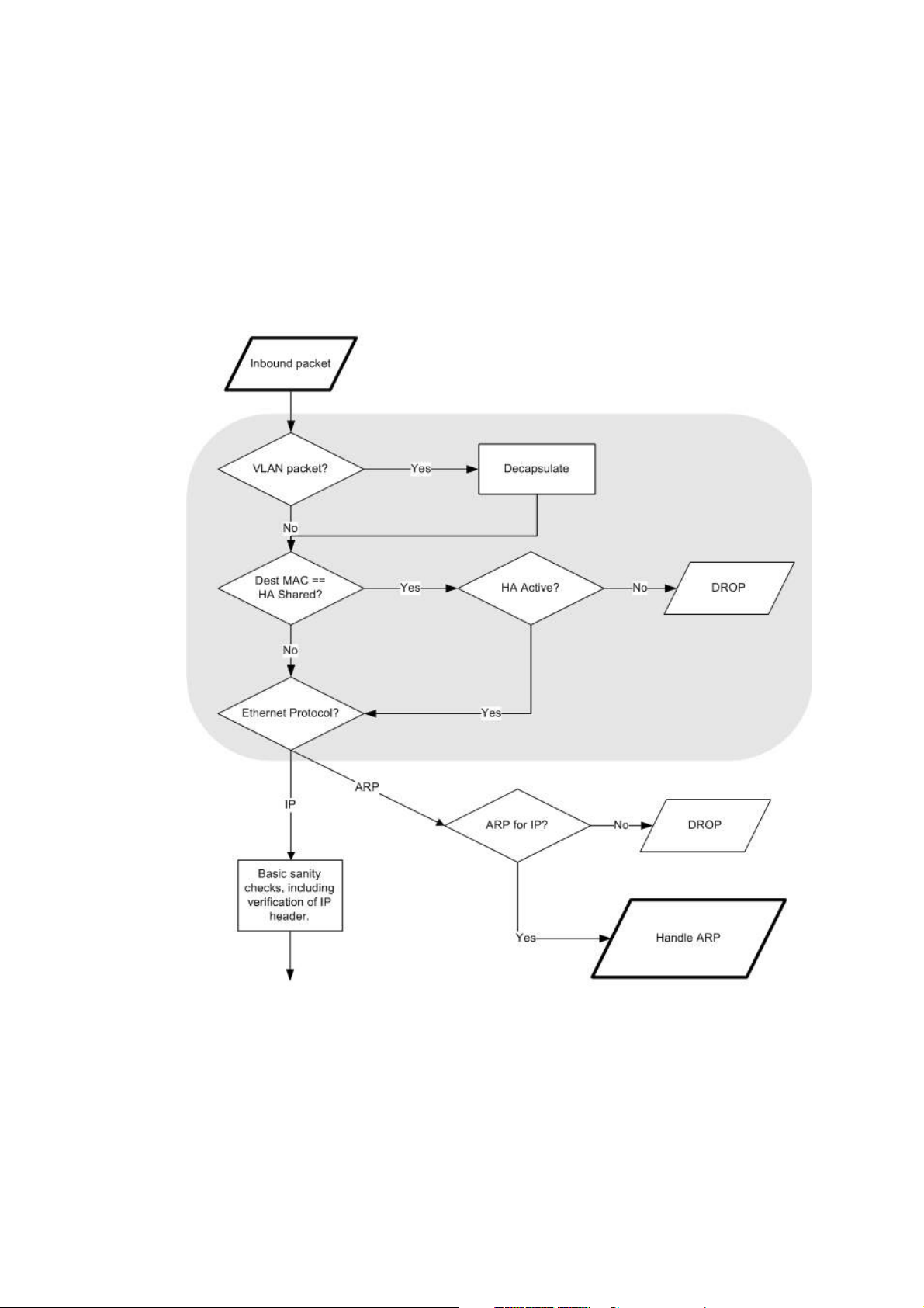
1.3. cOS Core State Engine Packet Flow
The diagrams in this section provide a summary of the flow of packets through the cOS Core
state-engine. There are three diagrams, each flowing into the next. It is not necessary to
understand these diagrams, however, they can be useful as a reference when configuring cOS
Core in certain situations.
Chapter 1: cOS Core Overview
Figure 1.1. Packet Flow Schematic Part I
The packet flow is continued on the following page.
26
Page 27
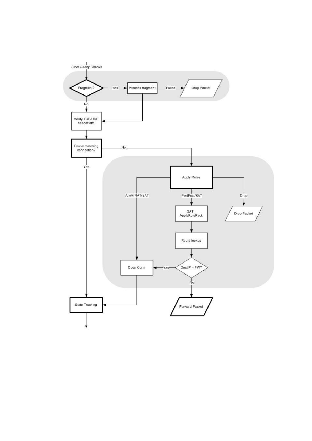
Chapter 1: cOS Core Overview
Figure 1.2. Packet Flow Schematic Part II
The packet flow is continued on the following page.
27
Page 28
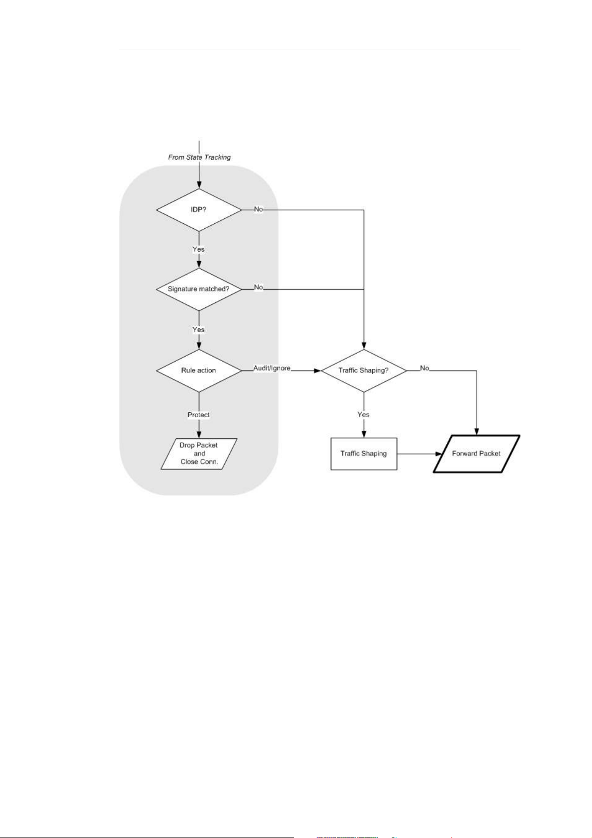
Chapter 1: cOS Core Overview
Figure 1.3. Packet Flow Schematic Part III
28
Page 29
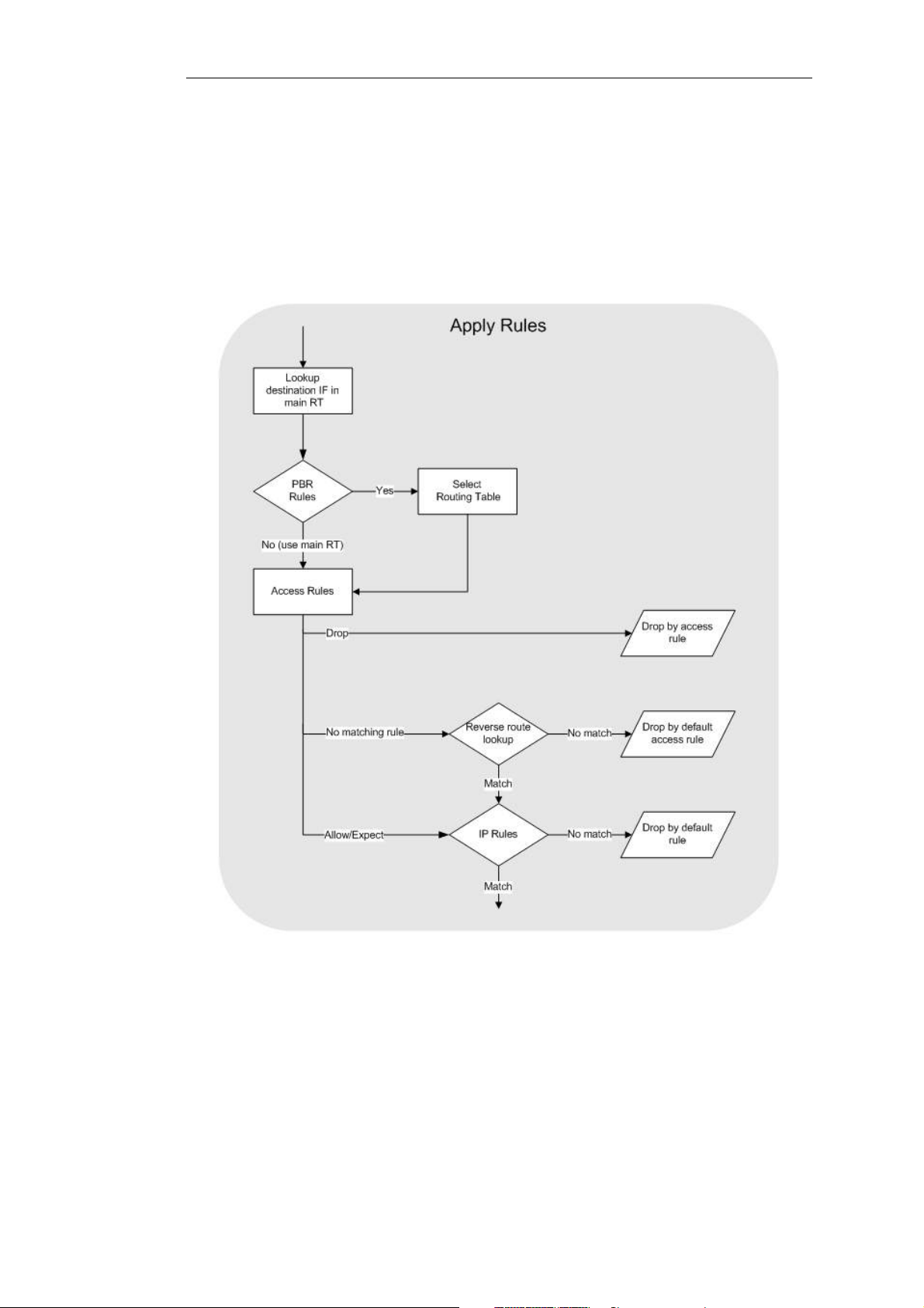
Chapter 1: cOS Core Overview
Apply Rules
The figure below presents the detailed logic of the Apply Rules function in Figure 1.2, “Packet Flow
Schematic Part II” above.
Figure 1.4. Expanded Apply Rules Logic
29
Page 30

Chapter 1: cOS Core Overview
30
Page 31

Chapter 2: Management and Maintenance
This chapter describes the management, operations and maintenance related aspects of cOS
Core.
• Managing cOS Core, page 31
• Events and Logging, page 73
• RADIUS Accounting, page 82
• Monitoring, page 89
• Diagnostic Tools, page 106
• Maintenance, page 112
• Licensing, page 121
2.1. Managing cOS Core
2.1.1. Overview
cOS Core is designed to give both high performance and high reliability. Not only does it provide
an extensive feature set, it also enables the administrator to be in full control of almost every
detail of the system. This means the product can be deployed in the most challenging
environments.
A good understanding on how cOS Core configuration is performed is crucial for proper usage of
the system. For this reason, this section provides an in-depth presentation of the configuration
subsystem as well as a description of how to work with the various management interfaces.
Management Interfaces
cOS Core provides the following management interfaces:
Clavister InControl InControl is a separate Clavister software product for the
centralized administration of multiple Clavister Security Gateways.
The product provides an intuitive graphical client which runs on a
standard Windows based PC. One or multiple clients communicate
with an InControl server running on the same or different Windows
31
Page 32

Chapter 2: Management and Maintenance
based computer. The server serves as a repository for all cOS Core
configuration data and mediates all management commands sent
by clients.
More information about InControl can be found in the separate
InControl Administrators Guide.
The Web Interface The Web Interface (also known as the Web User Interface or WebUI)
is built into cOS Core and provides a user-friendly and intuitive
graphical management interface, accessible from a standard web
browser.
The browser connects to one of the hardware's Ethernet interfaces
using HTTP or HTTPS and the cOS Core responds like a web server,
allowing web pages to be used as the management interface.
The Web Interface does not provide centralized management
control of multiple Clavister Security Gateways. One browser
window can communicate with one Clavister Security Gateway,
although it is possible to have multiple browser windows open at
the same time.
This feature is fully described in Section 2.1.3, “The Web Interface”.
The CLI The Command Line Interface (CLI), accessible locally via serial
console port or remotely using the Secure Shell (SSH) protocol,
provides the most fine-grained control over all parameters in cOS
Core.
This feature is fully described in Section 2.1.4, “The CLI”.
Secure Copy Secure Copy (SCP) is a widely used communication protocol for file
transfer. No specific SCP client is provided with cOS Core
distributions but there exists a wide selection of SCP clients
available for nearly all workstation platforms.
SCP is a complement to CLI usage and provides a secure means of
file transfer between the administrator's workstation and the
Clavister Security Gateway. Various files used by cOS Core can be
both uploaded and downloaded with SCP.
This feature is fully described in Section 2.1.6, “Secure Copy”.
Console Boot Menu Before cOS Core starts running, a console connected directly to the
Clavister Security Gateway's RS232 port can be used to do basic
configuration through the boot menu. This menu can be entered
by pressing any console key between power-up and cOS Core
starting. It is the Clavister firmware loader that is being accessed
with the boot menu.
The menu is fully described in Section 2.1.7, “The Console Boot
Menu”.
Remote Management Policies
Access to remote management interfaces can be regulated by a remote management policy so
the administrator can restrict management access based on source network, source interface
and username/password credentials.
32
Page 33

2.1.2. Default Administrator Accounts
By default, cOS Core has a local user database, AdminUsers, which contains two predefined user
accounts:
• Username admin with password admin.
This account has full administrative read/write privileges.
• Username audit with password audit.
This account is for monitoring purposes only and has read-only privileges.
Important
For security reasons, it is recommended to change the default passwords of the default
accounts as soon as possible after connecting with the Clavister Security Gateway.
Creating Additional Accounts
Chapter 2: Management and Maintenance
Extra user accounts can be created as required. Accounts can either belong to the Administrator
user group, in which case they have complete read/write administrative access. Alternatively,
they can belong to the Auditor user group, in which case they have read-only access.
Multiple Administration Logins
cOS Core does not allow more than one administrator account to be logged in at the same time.
If one administrator logs in, then a second or more will be allowed to login but they will only
have audit privileges. In other words the second or more administrators who login will only be
able to read configurations and will not be able to change them.
2.1.3. The Web Interface
cOS Core provides an intuitive Web Interface (WebUI) for management of the system via an
Ethernet interface using a standard web browser. This allows the administrator to perform
remote management from anywhere on a private network or the public Internet using a
standard computer without having to install client software.
Note: Recommended web browsers
The recommended browsers to use with the Web Interface are:
• Microsoft Internet Explorer
• Firefox
• Safari
• Chrome
• Opera
The Default Management Interface and IP Address
For new Clavister product models with factory defaults, a default internal IPv4 address of
192.168.1.1 is assigned by cOS Core to the interface indicated in the list below.
33
Page 34
Chapter 2: Management and Maintenance
Clavister Product Default Web Interface Management Interface
Lynx X8 G1
Eagle E5/E7 gesw
Wolf W3/W5 M1
Virtual Series If1
Changing the management interface and/or IP address from the default is described in
Section 2.1.8, “Changing Management Access”.
The Management Interface on Non-Clavister Hardware
For the Clavister Software Series product, when cOS Core runs on non-Clavister hardware, cOS
Core scans the available interfaces and allocates the 192.168.1.1 IP address to the first interface it
finds and gives this the logical name If1. Subsequent interfaces are then named If2, If3 and so on.
Trying to connect to each interface in turn with a web browser can reveal which has been
selected if it is not clear. cOS Core running under VMware names the virtual interfaces found in a
similar way.
Setting the Management Workstation IP
The default management Ethernet interface of the security gateway and the external
workstation computer's Ethernet interface must be members of the same logical IP network for
communication between them to succeed. Therefore, the connecting Ethernet interface of the
workstation must be manually assigned the following static IP values:
• IP address: 192.168.1.30
• Subnet mask: 255.255.255.0
• Default gateway: 192.168.1.1
For details on how to set the static IP address for Windows and MacOS workstations, see the
relevant Clavister Getting Started Guide for the platform being used.
Logging on to the Web Interface
To access the Web Interface using the factory default settings, launch a web browser on the
external workstation computer and point the browser at the IPv4 address: 192.168.1.1.
When performing initial connection to cOS Core, the administrator should use https:// as the
URL protocol in the browser (in other words, https://192.168.1.1 ). Using HTTPS ensures that
communication with cOS Core is secure.
Alternatively, http:// can be used for logon but this is not secure and should be used only across
internal, private networks.
If communication with the cOS Core is successfully established, a user authentication dialog
similar to the one shown below will then be shown in the browser window.
34
Page 35
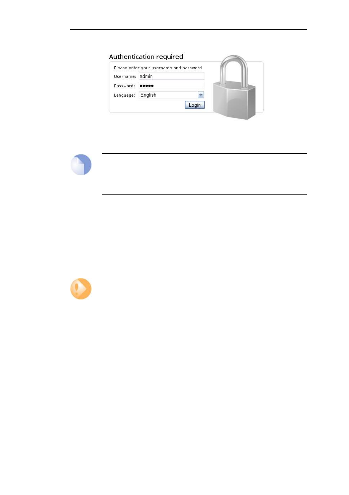
Chapter 2: Management and Maintenance
After entering a valid username and password the Login button is clicked. If the user credentials
are valid, the administrator is taken to the main Web Interface page.
Note: Password caching is prevented
The Web Interface prevents the caching of the password from the login credentials. This
is also done in other cOS Core features where a password is requested through a
browser screen. For example, VPN authentication.
First Time Web Interface Logon and the Setup Wizard
When logging on for the first time, the default username is always admin and the password is
admin .
After successful login, the Web Interface user interface will be presented in the browser window.
If no configuration changes have yet been uploaded to the Clavister Security Gateway, the cOS
Core Setup Wizard will start automatically to take a new user through the essential steps for cOS
Core setup and establishing public Internet access.
Important: Switch off popup blocking
Popup blocking must be disabled in the web browser to allow the cOS Core Setup
Wizard to run since this appears in a popup window.
The wizard can be terminated and setup up done as a series of separate steps through the Web
Interface if desired or alternatively through the CLI. Initial setup and the wizard are described in
detail in the relevant Getting Started Guide.
Multi-language Support
The Web Interface login dialog offers the option to select a language other than English for the
interface. Language support is provided by a set of separate resource files.
It may occasionally be the case that a cOS Core upgrade can contain features that temporarily
lack a complete non-English translation because of time constraints. In this case the original
English will be used as a temporary solution in place of a translation to the selected language.
The Web Browser Interface
On the left hand side of the Web Interface is a tree which allows navigation to the various sets of
35
Page 36
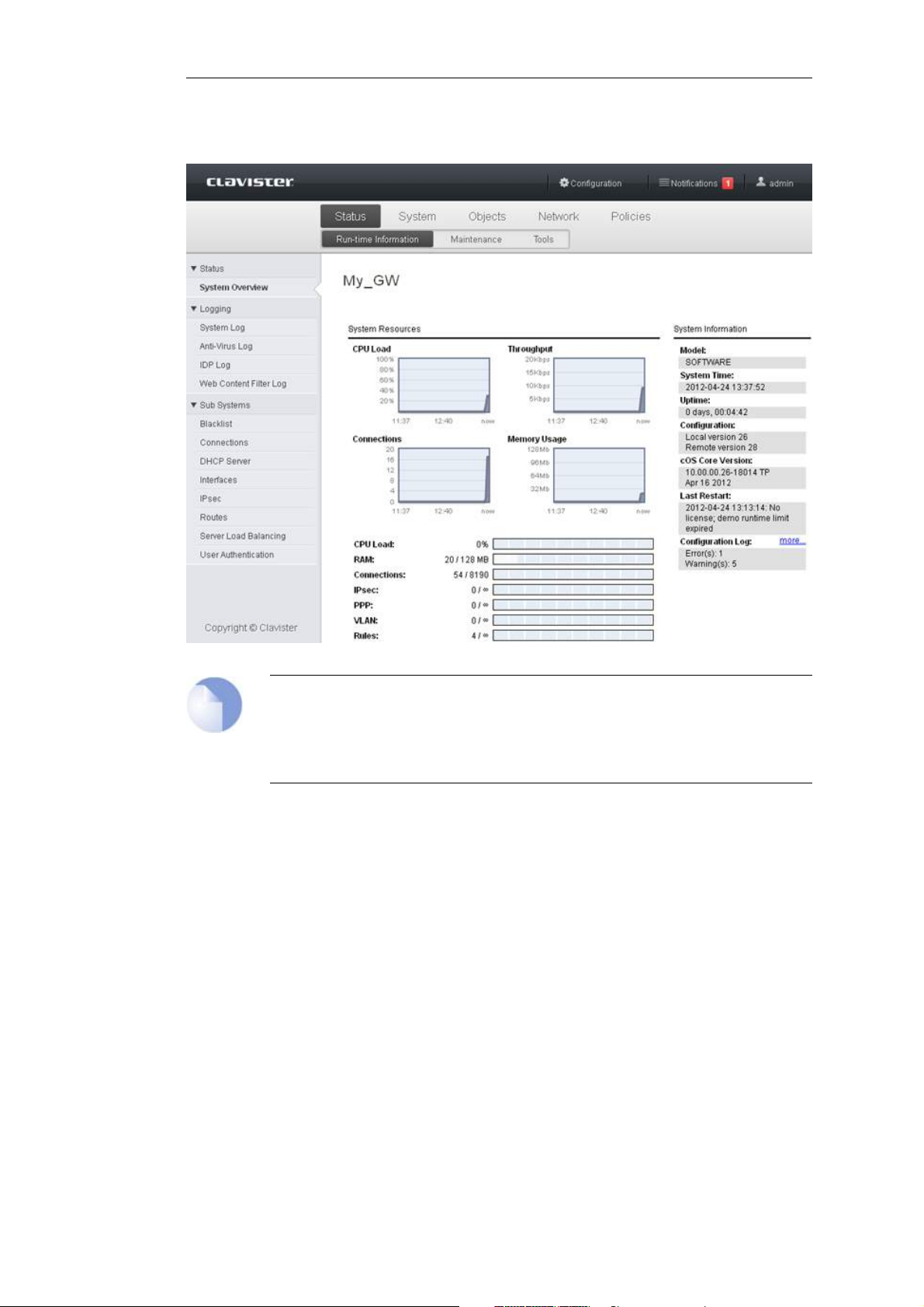
Chapter 2: Management and Maintenance
cOS Core objects. The central area of the Web Interface displays information about those
modules. Current performance information is shown by default.
Note: Remote management access
Access to the Web Interface is regulated by the configured remote management policy.
By default, the system will only allow web access from the internal network. For more
information about this topic, see Section 2.1.8, “Changing Management Access”.
Interface Layout
The main Web Interface page is divided into three major sections:
A. Menu bar The menu bar located at the top of the Web Interface contains a series of
buttons for accessing different aspects of the configuration.
B. Object Navigator The navigator located on the left-hand side of the Web Interface
is divided into a number of sections related to the chosen menu
bar item.
C. Main Window The main window contains configuration or status details corresponding
to the section selected in the menu bar or object navigator.
When displaying tables of information in the main window, right clicking
a line (for example, an IP rule) will bring up a context menu.
This context menu can be used to add a new object, delete the current,
36
Page 37
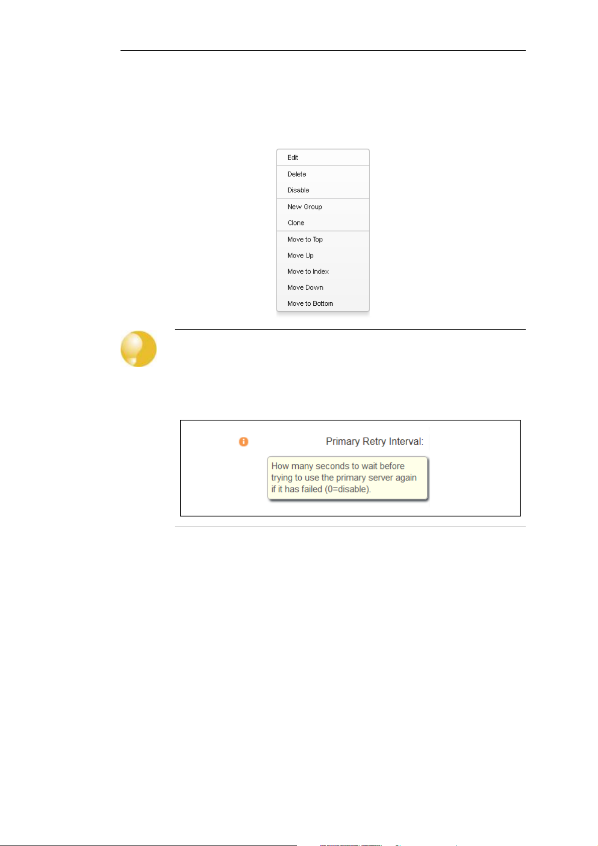
Chapter 2: Management and Maintenance
change the ordering and other operations. The Clone function is used to
make a complete copy of the current object and then add it as the last
object in the table. Below, is a typical example of the context menu.
Tip: Hover over textual items for additional information
Many of the textual items in the Web Interface have the ability to present additional
information about the item if the screen cursor is held over them. For example, the
screen shot below shows the information displayed when the cursor hovers over the
Primary Retry Interval field text in the RADIUS settings.
Activating Configuration Changes
As configuration changes are made through the Web Interface, they are not applied to the
current running configuration until the administrator asks for them to be activated. Activation is
done by choosing the Web Interface menu option Configuration > Save and Activate.
cOS Core will then perform a reconfigure operation which might cause only a slight, brief delay to
current data traffic. To prevent a change locking out the administrator, cOS Core will revert to the
old configuration if communication is lost with the web browser after a fixed time delay (30
seconds by default). This delay is discussed further in Section 2.1.8, “Changing Management
Access”.
Using CA Signed Certificates
By default, when the Web Interface is accessed with HTTPS, a self-signed certificate is sent to the
browser which must be explicitly accepted by the user. However, it is possible to use a CA signed
certificate and this can be done with certificate chaining. The next example demonstrates this.
37
Page 38
Chapter 2: Management and Maintenance
Example 2.1. Remote Management via HTTPS with CA Signed Certificates
Command-Line Interface
Device:/> set Settings RemoteMgmtSettings
Web Interface
1. Go to: System > Device > Remote Management > Advanced Settings
2. Under WebUI enter the HTTPS Certificate and the Remote Management certificates.
3. Click OK
These same CA signed certificates are also used by the cOS Core SSL VPN feature when a user is
connecting for the first time and a dialog of options is displayed.
HTTPSCertificate=HostA
HTTPSRootCertificates=RootA2,RootA1,RootA3
Caution: Don't expose the management interface to the Internet
The above examples are provided for illustrative purposes only. It is never recommended
to expose any management interface to any user on the Internet.
Restarting cOS Core with the Web Interface
The Web Interface can be used to restart cOS Core by selecting the option Status >
Maintenance > Reset & Restore. The following restart options are available:
• Reconfigure
This does not restart the hardware but only reloads the configuration. This is equivalent to
the reconf CLI command. In most cases, all connections including VPN tunnels are unaffected.
Apart from reloading the configuration, many of cOS Core's internal data structures related to
rules and traffic processing are reinitialized and this can sometimes be a way to solve
problems related to memory management.
• Restart
This restarts the hardware and is equivalent to the shutdown CLI command. Only cOS Core
restarts and not the cOS Core loader. This is the usual method of performing a restart.
• Reboot
This restarts the hardware and is equivalent to the shutdown -reboot CLI command. It is
similar to the previous Restart option with a graceful shutdown but is also equivalent to
switching power off and on so that the cOS Core boot program is also reloaded. This option is
not normally used in standard operation and also requires longer for the restart.
Logging out from the Web Interface
38
Page 39

After finishing working with the Web Interface, it is advisable to always logout to prevent other
users with access to the workstation getting unauthorized access to cOS Core. Logout is
achieved by clicking on the Logout button at the right of the menu bar.
Management Traffic Routing with VPN Tunnels
If there is a problem with the management interface when communicating alongside VPN
tunnels, check the main routing table and look for an all-nets route to the VPN tunnel.
Management traffic may be using this route.
If no specific route is set up for the management interface then all management traffic coming
from cOS Core will automatically be routed into the VPN tunnel. If this is the case then a route
should be added by the administrator to route management traffic destined for the
management network to the correct interface.
2.1.4. The CLI
cOS Core provides a Command Line Interface (CLI) for administrators who prefer or require a
command line approach to administration, or who need more granular control of system
configuration. The CLI is available either locally through the serial console port (connection to
this is described below), or remotely via an Ethernet interface using the Secure Shell (SSH)
protocol from an SSH client.
Chapter 2: Management and Maintenance
The CLI provides a comprehensive set of commands that allow the display of configuration data
as well as allowing runtime data to be displayed and allowing system maintenance tasks to be
performed.
This section only provides a summary for using the CLI. For a complete reference for all CLI
commands, see the separate Clavister CLI Reference Guide.
The most often used CLI commands are:
• add - Adds an object such as an IP address or a rule to a cOS Core configuration.
• set - Sets some property of an object to a value. For example, this might be used to set the
source interface on an IP rule.
• show - Displays the current categories or display the values of a particular object.
• delete - Deletes a specific object.
CLI Command Structure
CLI commands usually have the structure:
<command> <object_category> <object_type> <object_name>
For example, to display an IP address object called my_address, the command would be:
Device:/> show Address IP4Address my_address
The object category in this case is Address and the type within this category is IPAddress.
When typing commands, the object category can be left out where the command's meaning is
unambiguous. For example, the show command above could have been entered as:
Device:/> show IPAddress my_address
However, tab completion will always assume the category is included. For example, tab
39
Page 40
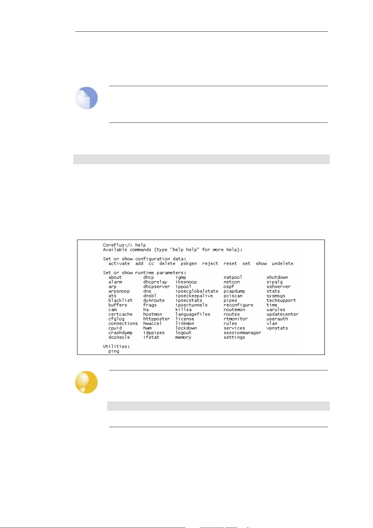
Chapter 2: Management and Maintenance
completion would not be able to help complete the above command if the tab is pressed during
or after the IPAddress object type.
The same object name could be used within two different categories or types although this is
best avoided in order to avoid ambiguity when reading configurations.
Note: The terms Category and Context
When describing the CLI, the terms object category and object context are used
interchangeably.
A command like add can also include object properties. To add a new IP4Address object with an IP
address of 10.49.02.01, the command would be:
Device:/> add IP4Address my_address Address=10.49.02.01
The object type can be optionally preceded by the object category. A category groups together a
set of types and mainly used with tab completion which is described below.
CLI Help
The CLI help command will show all available command options. A screen shot of the first part of
the output from the help command is shown below:
Tip: Getting help about help
Typing the CLI command:
Device:/> help help
will give information about the help command itself.
The CLI Command History
Just like the console in many versions of Microsoft Windows™, the up and down arrow keys allow
the user to move through the list of commands in the CLI command history. For example,
40
Page 41

Chapter 2: Management and Maintenance
pressing the up arrow key once will make the last command executed appear at the current CLI
prompt. After a command appears it can be re-executed in its original form or changed first
before execution.
Tab Completion
Remembering all the commands and their options can be difficult. cOS Core provides a feature
called tab completion which means that pressing the tab key will cause automatically completion
of the current part of the command. If completion is not possible then pressing the tab key will
alternatively display the possible command options that are available.
Optional Parameters Are Tab Completed Last
Tab completion does not work with optional parameters until all the mandatory parameters
have been entered.
For example, when creating an IP rule for a particular IP rule set, the command line might begin:
Device:/> add IPRule
If the tab key is now pressed, the mandatory parameters are displayed by cOS Core:
A value is required for the following properties:
Action DestinationNetwork SourceInterface
DestinationInterface Service SourceNetwork
The Name parameter is not in this list since it is not mandatory because rules can be referenced
with their index number. Similarly, the following might be entered:
Device:/> add IPRule Na
If the tab key is now pressed, the letters Na will not be completed to be Name= because Name is
optional and all the mandatory parameters must be entered before tab completion works for
optional parameters.
Note: CLI commands in this guide are reformatted
In order to make the individual elements of CLI commands in this guide clearer, they are
broken into indented separate lines. In a console window they would appear as a single
continuous line which folds at the right margin.
For example, if the following command is typed:
Device:/> add IPRule
SourceInterface=If2
SourceNetwork=all-nets
DestinationInterface=If2
DestinationNetwork=all-nets
Action=Allow
Service=all_services
Na
If the tab key is now pressed, the letters Na will now be completed to be Name= because all the
mandatory parameters have already been entered.
Note: Rule names are recommended
Even when it is optional, it is recommended that a Name value is assigned to a rule. This
41
Page 42

Chapter 2: Management and Maintenance
makes examining and understanding the configuration easier.
Getting the Default or Current Property Value
The period "." character before a tab can be used to automatically fill in the default value for an
object property in an Add command. For example:
Device:/> add LogReceiver LogReceiverSyslog log_example
Address=example_ip
LogSeverity=.<tab>
This will fill in the default value for LogSeverity:
Device:/> add LogReceiverSyslog example
Address=example_ip
LogSeverity=Emergency,Alert,Critical,Error,Warning,Notice,Info
This severity list can then be edited with the back arrow and backspace keys. A default value is
not always available. For example, the Action of an IP rule has no default.
This same sequence can be used to get the current property value in a Set command. For
example:
Device:/> set LogReceiver LogReceiverSyslog log_example Address=.<tab>
This will display the current value for the Address property.
Appending Property Values
Another usage of the period character before a tab is to automatically fill in the current value of
an object property in a command line. This is very useful when there is a need to append a new
value to a list of pre-existing values.
For example, the following unfinished command may have been typed:
Device:/> set Address IP4Address If1_ip Address=
If a period "." followed by a tab is now entered, cOS Core displays the current value for Address. If
that value were the IPv4 list 10.6.58.10,192.168.2.1 then the unfinished command line will
automatically become:
Device:/> set Address IPAddress If1_ip Address=10.6.58.10,192.168.2.1
The displayed values can then be added to or changed with the backspace and back arrow keys
before completing the command.
Object Categories
It has been mentioned that objects are grouped by type, such as IP4Address. Types themselves
are grouped by category. The type IP4Address belongs to the category Address. The main use of
categories is in tab completion when searching for the right object type to use.
If a command such as add is entered and then the tab key is pressed, cOS Core displays all the
available categories. By choosing a category and then pressing tab again all the object types for
that category is displayed. Using categories means that the user has a simple way to specify what
kind of object they are trying to specify and a manageable number of options are displayed after
pressing tab.
42
Page 43

Chapter 2: Management and Maintenance
Not all object types belong in a category. The object type UserAuthRule is a type without a
category and will appear in the category list after pressing tab at the beginning of a command.
The category is sometimes also referred to as the CLI context. The category does not have to be
entered for the command to be valid but always appears when using tab completion. As
discussed later, when commands are created automatically using CLI scripting, cOS Core omits
the category in the commands it creates.
Selecting Object Categories
With some categories, it is necessary to first choose a member of that category with the cc
(change category) command before individual objects can be manipulated. This is the case, for
example, with routes. There can be more than one routing table, so when adding or
manipulating a route we first have to use the cc command to identify which routing table we are
interested in.
Suppose a route is to be added to the routing table main. The first command would be:
Device:/> cc RoutingTable main
Device:/main>
Notice that the command prompt changes to indicate the current category. The route can now
be added:
Device:/main> add Route Name=new_route1 Interface=lan Network=If1_net
To deselect the category, the command is cc on its own:
Device:/main> cc
Device:/>
The categories that require an initial cc command before object manipulation have a "/"
character following their names when displayed by a show command. For example:
RoutingTable/.
Specifying Multiple Property Values
Sometimes a command property may need multiple values. For example, some commands use
the property AccountingServers and more than one value can be specified for this property. When
specifying multiple values, they should be separated by a comma "," character. For example, if
three servers server1, server2, server3 need to be specified then the property assignment in the
command would be:
AccountingServers=server1,server2,server3
Inserting into Rule Lists
Rule lists such as the IP rule set have an ordering which is important. When adding using the CLI
add command, the default is to add a new rule to the end of a list. When placement at a
particular position is crucial, the add command can include the Index= parameter as an option.
Inserting at the first position in a list is specified with the parameter Index=1 in an add command,
the second position with the parameter Index=2 and so on.
Referencing by Name
43
Page 44

Chapter 2: Management and Maintenance
The naming of some objects is optional and is done with the Name= parameter in an add
command. An object, such as a threshold rule, will always have an Index value which indicates its
position in the rule list but can optionally be allocated a name as well. Subsequent manipulation
of such a rule can be done either by referring to it by its index, that is to say its list position, or by
alternatively using the name assigned to it.
The CLI Reference Guide lists the parameter options available for each cOS Core object, including
the Name= and Index= options.
Using Unique Names
For convenience and clarity, it is recommended that a name is assigned to all objects so that it
can be used for reference if required. Reference by name is particularly useful when writing CLI
scripts. For more on scripts see Section 2.1.5, “CLI Scripts”.
The CLI will enforce unique naming within an object type. For reasons of backward compatibility
to earlier cOS Core releases, an exception exists with IP rules which can have duplicate names,
however it is strongly recommended to avoid this. If a duplicate IP rule name is used in two IP
rules then only the Index value can uniquely identify each IP rule in subsequent CLI commands.
Referencing an IP rule with a duplicated name will fail and result in an error message.
Using Hostnames in the CLI
For certain CLI commands, IP addresses can optionally be specified as a textual hostname instead
an IP4Address object or raw IP address such as 192.168.1.10. When this is done, the hostname
must be prefixed with the letters dns: to indicate that a DNS lookup must be done to resolve the
hostname to an IP address. For example, the hostname host.company.com would be specified as
dns:host.company.com in the CLI.
The parameters where this might be used with the CLI are:
• The Remote Endpoint for IPsec, L2TP and PPTP tunnels.
• The Host for LDAP servers.
When DNS lookup needs to be done, at least one public DNS server must be configured in cOS
Core for hostnames to be translated to IP addresses.
InControl Domains
When using InControl as the means of configuring cOS Core, it is possible to use the logical
concept of a Domain to share the same object between security gateways.
The Domain is a construct that only exists in InControl and not in individual security gateway
configurations. For this reason, the CLI cannot be used to manipulate domains.
Furthermore, an object in a InControl domain may not necessarily be used in the configuration of
a security gateway which is a child of that domain. If this is the case, the CLI cannot be used to
manipulate a domain object on a security gateway that does not use it.
Serial Console CLI Access
The serial console port is a local RS-232 port on the Clavister Security Gateway that allows direct
access to the cOS Core CLI through a serial connection to a PC or dumb terminal. To locate the
serial console port on Clavister hardware, see the corresponding hardware installation guide.
To use the console port, the following equipment is required:
44
Page 45

Chapter 2: Management and Maintenance
• A terminal or a computer with a serial port and the ability to emulate a terminal (such as
using the Hyper Terminal software included in some Microsoft Windows™ editions). The serial
console port uses the following default settings: 9600 bps, No parity, 8 data bits and 1 stop bit.
• A RS-232 cable with appropriate connectors. An appliance package includes a RS-232
null-modem cable.
To connect a terminal to the console port, follow these steps:
1. Set the terminal protocol as described previously.
2. Connect one of the connectors of the RS-232 cable directly to the console port on the
Clavister Security Gateway system.
3. Connect the other end of the cable to the terminal or the serial connector of the computer
running the communications software.
4. Press the enter key on the terminal. The cOS Core login prompt should appear on the
terminal screen.
Changing the Serial Console Line Speed
The console line speed can be changed either through the Web Interface or through the CLI.
Example 2.2. Setting the Console Line Speed
In this example the console line speed is set to 19200 bps.
Command-Line Interface
Device:/> set COMPortDevice COM1 BitsPerSecond=19200
InControl
Follow the same steps used for the Web Interface below.
Web Interface
Go to: System > Advanced Settings > Com Port Devices
Click the console port line, configure the speed and then click OK
Note: A cOS Core restart is required after changing the speed
After changing the speed, the new setting will only come into effect after restarting cOS
Core which can be done with the command:
Device:/> shutdown
A shutdown always restarts cOS Core.
45
Page 46

Chapter 2: Management and Maintenance
SSH (Secure Shell) CLI Access
The SSH (Secure Shell) protocol can be used to access the CLI over the network from a remote
host. SSH is a protocol primarily used for secure communication over insecure networks,
providing strong authentication and data integrity. SSH clients are freely available for almost all
hardware platforms.
cOS Core supports version 1, 1.5 and 2 of the SSH protocol. SSH access is regulated by the remote
management policy in cOS Core, and is disabled by default.
Example 2.3. Enabling SSH Remote Access
This example shows how to enable remote SSH access from the lan_net network through the lan
interface by adding a rule to the remote management policy.
Command-Line Interface
Device:/> add RemoteManagement RemoteMgmtSSH ssh
Network=lan_net
Interface=lan
LocalUserDatabase=AdminUsers
Web Interface
1. Go to: System > Device > Remote Management > Add > Secure Shell Management
2. Enter a Name for the SSH remote management policy, for example ssh_policy
3. Select the following:
• User Database: AdminUsers
• Interface: lan
• Network: lan_net
4. Click OK
Logging on to the CLI
When access to the CLI has been established to cOS Core through the serial console or an SSH
client, the administrator will need to logon to the system before being able to execute any CLI
command. This authentication step is needed to ensure that only trusted users can access the
system, as well as providing user information for auditing.
When accessing the CLI remotely through SSH, cOS Core will respond with a login prompt. Enter
the username and press the Enter key, followed by the password and then Enter again. After the
first startup, cOS Core will allow administrator login with the username admin and the password
admin. This default password should be changed as soon as possible.
After a successful logon, the CLI command prompt will appear:
Device:/>
If a welcome message has been set then it will be displayed directly after the logon. For security
reasons, it is advisable to either disable or anonymize the CLI welcome message.
46
Page 47

Chapter 2: Management and Maintenance
Changing the admin User Password
It is recommended to change the default password of the admin account from admin to
something else as soon as possible after initial startup. User passwords can be any combination
of characters and cannot be greater than 256 characters in length. It is recommended to use only
printable characters.
To change the password to, for example, my-password the following CLI commands are used.
First we must change the current category to be the LocalUserDatabase called AdminUsers (which
exists by default):
Device:/> cc LocalUserDatabase AdminUsers
We are now in AdminUsers and can change the password of the admin user:
Device:/AdminUsers> set User admin Password="my-password"
Finally, we return the current category to the top level:
Device:/AdminUsers> cc
Note: The console password is separate
The password that can be set to protect direct serial console access is a separate
password and should not be confused with the passwords related to user accounts. The
console password is described in Section 2.1.7, “The Console Boot Menu”.
Changing the CLI Prompt
The default CLI prompt is:
Device:/>
This can be customized, for example, to my-prompt:/>, by using the CLI command:
Device:/> set device name="my-prompt"
The CLI Reference Guide uses the command prompt Device:/> throughout.
Tip: The CLI prompt is the Web Interface device name
When the command line prompt is changed to a new string value, this string also
appears as the new device name in the top level node of the Web Interface navigation
tree.
Activating and Committing Changes
If any changes are made to the current configuration through the CLI, those changes will not be
uploaded to cOS Core until the command:
Device:/> activate
is issued. Immediately following the activate command, the command:
47
Page 48

Chapter 2: Management and Maintenance
Device:/> commit
should be issued to make those changes permanent.
Note: Examples in this guide assume activation will be performed
Most of the examples in this guide deal with editing a cOS Core configuration. The final
activation step is usually not explicitly stated.
If the commit command is not entered after a activate command within a given time period (the
default is 30 seconds) then the changes are automatically undone and the old configuration
restored. This topic is discussed further in Section 2.1.8, “Changing Management Access”.
Note: CLI commits terminate Web Interface sessions
There is a possible side effect of committing changes through the CLI. Any Web Interface
browser session that is logged in at the time of the commit will require that the user logs
in again. This is because the Web Interface view of the configuration may no longer be
valid.
Restarting and Rebooting cOS Core with the CLI
The CLI can be used to reboot cOS Core using the command:
Device:/> shutdown
This command performs a graceful shutdown of all connections and VPN tunnels before the
restart and is sufficient for most situations that require a system restart. In includes a reloading of
the configuration (in other words, a reconfiguration operation).
To shut down and restart both cOS Core and completely reinitialize the hardware, including the
cOS Core loader (equivalent to switching the hardware off then on), use the command:
Device:/> shutdown -reboot
The -reboot option is rarely needed in normal circumstances and because it requires more time
for the restart it is best not to use it. When cOS Core is upgraded the -reboot option is executed
automatically during the upgrade process.
The same restart functions can be performed with the Web Interface by selecting the option
Status > Maintenance > Reset & Restore > Restart.
Reconfiguring cOS Core with the CLI
cOS Core can be forced to reread and reload the current configuration with the command:
Device:/> reconf
Apart from reloading the configuration, many of cOS Core's internal data structures related to
rules and traffic processing are reinitialized. It is not usual to execute a reconfigure during normal
operation but it can sometimes be a way to solve transient problems related to cOS Core
memory management.
Unlike the system restart described above, a reconfiguration does not usually affect current
connections or VPN tunnels. However, with some IPsec tunnel changes, a reconfiguration will
48
Page 49

Chapter 2: Management and Maintenance
mean the tunnels are lost and have to be re-established because the tunnel SAs are no longer
valid.
Checking Configuration Integrity
After changing a cOS Core configuration and before issuing the activate and commit commands,
it is possible to explicitly check for any problems in a configuration using the command:
Device:/> show -errors
This will cause cOS Core to scan the configuration about to be activated and list any problems. A
possible problem that might be found in this way is a reference to an IP object in the address
book that does not exist in a restored configuration backup.
Logging off from the CLI
After finishing working with the CLI, it is recommended to logout in order to avoid letting
anyone getting unauthorized access to the system. Log off by using the exit or the logout
command.
Configuring Remote Management Access on an Interface
Remote management access may need to be configured through the CLI. Suppose management
access is to be through Ethernet interface If2 which has an IP address 10.8.1.34.
Firstly, we set the values for the IPv4 address objects for If2 which already exist in the cOS Core
address book, starting with the interface IP:
Device:/> set Address IP4Address InterfaceAddresses/If2_ip
The network IP address for the interface must also be set to the appropriate value:
Device:/> set Address IP4Address InterfaceAddresses/If2_net
In this example, local IP addresses are used for illustration but these could be public IPv4
addresses instead. It is also assumed that the default address objects for the configuration are
stored in an address book folder called InterfaceAddresses.
Next, create a remote HTTP management access object, in this example called HTTP_If2:
Device:/> add RemoteManagement RemoteMgmtHTTP HTTP_If2
Address=10.8.1.34
Address=10.8.1.0/24
Interface=If2
Network=all-nets
LocalUserDatabase=AdminUsers
AccessLevel=Admin
HTTP=Yes
If we now activate and commit the new configuration, remote management access via the IPv4
address 10.8.1.34 is now possible using a web browser. If SSH management access is required
then a RemoteMgmtSSH object should be added.
The assumption made with the above commands is that an all-nets route exists to the ISP's
gateway. In other words, Internet access has been enabled for the Clavister Security Gateway.
Managing Management Sessions with sessionmanager
49
Page 50

Chapter 2: Management and Maintenance
The CLI provides a command called sessionmanager for managing management sessions
themselves. The command can be used to manage all types of management sessions, including:
• Secure Shell (SSH) CLI sessions.
• Any CLI session through the serial console interface.
• Secure Copy (SCP) sessions.
• Web Interface sessions connected by HTTP or HTTPS.
• Sessions based on the Clavister proprietary NetCon protocol.
The command without any options gives a summary of currently open sessions:
Device:/> sessionmanager
Session Manager status
----------------------
Active connections : 3
Maximum allowed connections : 64
Local idle session timeout : 900
NetCon idle session timeout : 600
To see a list of all sessions use the -list option. Below, is some typical output showing the local
console session:
Device:/> sessionmanager -list
User Database IP Type Mode Access
-------- ---------------- --------- ------- ------- --------
local <empty> 0.0.0.0 local console admin
If the user has full administrator privileges, they can forcibly terminate another management
session using the -disconnect option of the sessionmanager command.
The sessionmanager command options are fully documented in the CLI Reference Guide.
2.1.5. CLI Scripts
To allow the administrator to easily store and execute sets of CLI commands, cOS Core provides a
feature called CLI scripting. A CLI script is a predefined sequence of CLI commands which can be
executed after they are saved to a file and the file is then uploaded to the Clavister Security
Gateway.
The steps for creating a CLI script are as follows:
1. Create a text file with a text editor containing a sequential list of CLI commands, one per
line.
The Clavister recommended convention is for these files to use the file extension .sgs
(Security Gateway Script). The filename, including the extension, should not be more than 16
characters.
2. Upload the file to the Clavister Security Gateway using Secure Copy (SCP). Script files must
be stored in a directory under the root called /scripts. SCP uploading is discussed in detail in
Section 2.1.6, “Secure Copy”.
3. Use the CLI command script -execute to run the script file.
50
Page 51

Chapter 2: Management and Maintenance
The CLI script command is the tool used for script management and execution. The complete
syntax of the command is described in the CLI Reference Guide and specific examples of usage are
detailed in the following sections. See also Section 2.1.4, “The CLI” in this manual.
Note
Uploaded CLI script files are not held in permanent memory and will disappear after
system restarts.
Only Four Commands are Allowed in Scripts
The commands allowed in a script file are limited to four and these are:
• add
• set
• delete
• cc
If any other command appears in a script file, it is ignored during execution and a warning
message is output. For example, the ping command will be ignored.
Executing Scripts
As mentioned above, the script -execute command launches a named script file that has been
previously uploaded to the Clavister Security Gateway. For example, to execute the script file
my_script.sgs which has already been uploaded, the CLI command would be:
Device:/> script -execute -name=my_script.sgs
Script Variables
A script file can contain any number of script variables which are called:
$1, $2, $3, $4......$n
The values substituted for these variable names are specified as a list at the end of the script
-execute command line. The number n in the variable name indicates the variable value's position
in this list. $1 comes first, $2 comes second and so on.
Note: The symbol $0 is reserved
Notice that the name of the first variable is $1. The variable $0 is reserved and is always
replaced before execution by the name of the script file itself.
For example, a script called my_script.sgs is to be executed with IP address 126.12.11.01 replacing
all occurrences of $1 in the script file and the string If1 address replacing all occurrences of $2.
The file my_script.sgs contains the single CLI command line:
add IP4Address If1_ip Address=$1 Comments=$2
To run this script file after uploading, the CLI command would be:
51
Page 52

Chapter 2: Management and Maintenance
Device:/> script -execute -name=my_script.sgs 126.12.11.01 "If1 address"
When the script file runs, the variable replacement would mean that the file becomes:
add IP4Address If1_ip Address=126.12.11.01 Comments="If1 address"
Script Validation and Command Ordering
CLI scripts are not, by default, validated. This means that the written ordering of the script does
not matter. There can be a reference to a configuration object at the beginning of a script which
is only created at the end of the script.
Although this approach might seem illogical, it is done to improve the readability of scripts. If
something always has to be created before it is referred to then this can result in confused and
disjointed script files and in large script files it is often preferable to group together related CLI
commands.
Error Handling
If an executing CLI script file encounters an error condition, the default behavior is for the script
to terminate. This behavior can be overridden by using the -force option.
For example, to run a script file called my_script2.sgs in this way so that errors do not terminate
execution, the CLI command would be:
Device:/> script -execute -name=my_script2.sgs -force
If -force is used, the script will continue to execute even if errors are returned by a command in
the script file.
Script Output
Any output from script execution will appear at the CLI console. Normally this output only
consists of any error messages that occur during execution. To see the confirmation of each
command completing, the -verbose option should be used:
Device:/> script -execute -name=my_script2.sgs -verbose
Saving Scripts
When a script file is uploaded to the Clavister Security Gateway, it is initially kept only in
temporary RAM memory. If cOS Core restarts then any uploaded scripts will be lost from this
volatile memory and must be uploaded again to run. To store a script between restarts, it must
explicitly be moved to non-volatile cOS Core disk memory by using the script -store command.
For example, to move my_script.sgs to non-volatile memory, the command would be:
Device:/> script -store -name=my_script.sgs
Alternatively, all scripts can be moved to non-volatile memory with the command:
Device:/> script -store -all
52
Page 53

Chapter 2: Management and Maintenance
Removing Scripts
To remove a saved script, the script -remove command can be used. For example, to remove the
my_script.sgs script file, the command would be:
Device:/> script -remove -name=my_script.sgs
Listing Scripts
The script on its own, command without any parameters, lists all the scripts currently available
and indicates the size of each script as well as the type of memory where it resides (residence in
non-volatile memory is indicated by the word "Disk" in the Memory column).
Device:/> script
Name Storage Size (bytes)
-------------- ------------ --------------
my_script.sgs RAM 8
my_script2.sgs Disk 10
To list the content of a specific uploaded script file, for example my_script.sgs the command
would be:
Device:/> script -show -name=my_script.sgs
Creating Scripts Automatically
When the same configuration objects needs to be copied between multiple Clavister Security
Gateways, then one way to do this with the CLI is to create a script file that creates the required
objects and then upload to and run the same script on each device.
If we already have a cOS Core installation that already has the objects configured that need to be
copied, then running the script -create command on that installation provides a way to
automatically create the required script file. This script file can then be downloaded to the local
management workstation and then uploaded to and executed on other Clavister Security
Gateways to duplicate the objects.
For example, suppose the requirement is to create the same set of IP4Address objects on
several Clavister Security Gateways that already exist on a single unit. The administrator would
connect to the single unit with the CLI and issue the command:
Device:/> script -create Address IP4Address -name new_script.sgs
This creates a script file called new_script_sgs which contains all the CLI commands necessary to
create all IP4Address address objects in that unit's configuration. The created file's contents
might, for example, be:
add IP4Address If1_ip Address=10.6.60.10
add IP4Address If1_net Address=10.6.60.0/24
add IP4Address If1_br Address=10.6.60.255
add IP4Address If1_dns1 Address=141.1.1.1
"
"
"
The file new_script_sgs can then be downloaded with SCP to the local management workstation
and then uploaded and executed on the other Clavister Security Gateways. The end result is that
all units will have the same IP4Address objects in their address book.
53
Page 54

Chapter 2: Management and Maintenance
The following should be noted for automatically created scripts:
• Automatically created scripts omit the object category.
In the created script example above, adding an IP address is done with the command:
add IP4Address...
This is instead of the usual way of qualifying the object with its category name:
add Address IP4Address...
Both are valid forms of the command. If an object type can be uniquely identified with its
name, its object category need not be specified. With automatically generated scripts, this is
always the case. This shortened form can also be used when typing the entire command in a
CLI console although tab completion will always include the object category.
• The script filename length has a limit.
The name of the file created using the -create option cannot be greater than 16 characters in
length (including the extension) and the filetype should always be .sgs.
• Both Set and Add appear in scripts.
The default configuration objects will have a Set action and the objects added to the default
configuration will have an Add action.
• Creating scripts for the entire configuration.
It is possible to create a script for the entire configuration with the command:
Device:/> script -create -name=entire_config.sgs
This can be useful if the entire configuration is to be recreated.
Note that any objects marked for deletion will not be included in the script
• Some objects are always excluded from created script files.
Certain aspects of a configuration which are hardware dependent cannot have a script file
entry created when using the -create option. This is true when the CLI node type in the script
-create command is one of the following:
• COMPortDevice
• Ethernet
• EthernetDevice
• Device
These node types are skipped when the script file is created and cOS Core gives the message
No objects of selected category or type.
Tip: Listing created script commands on the console
To list the created CLI commands on the console instead of saving them to a file, leave
out the option -name= in the script -create command.
54
Page 55

Commenting Script Files
Any line in a script file that begins with the # character is treated as a comment. For example:
# The following line defines the If1 IP address
add IP4Address If1_ip Address=10.6.60.10
Scripts Running Other Scripts
It is possible for one script to run another script. For example, the script my_script.sgs could
contain the line:
cOS Core allows the script file my_script2.sgs to execute another script file and so on. The
maximum depth of this script nesting is 5.
2.1.6. Secure Copy
To upload and download files to or from the Clavister Security Gateway, the secure copy (SCP)
protocol can be used. SCP is based on the SSH protocol and many freely available SCP clients
exist for almost all platforms. The command line examples below are based on the most
common command format for SCP client software.
Chapter 2: Management and Maintenance
script -execute -name my_script2.sgs
SCP Command Format
SCP command syntax is straightforward for most console based clients. The basic command
used here is scp followed by the source and destination for the file transfer.
Upload is performed with the command:
> scp <local_filename> <destination_gateway>
Download is done with the command:
> scp <source_gateway> <local_filename>
The source or destination Clavister Security Gateway is of the form:
<user_name>@<gateway_ip_address>:<filepath>.
For example: [email protected]:config.bak. The <user_name> must be a defined cOS Core user
in the administrator user group.
Note: SCP examples do not show the password prompt
SCP will normally prompt for the user password after the command line but that prompt
is not shown in the examples given here.
The following table summarizes the operations that can be performed between an SCP client
and cOS Core:
File type Upload possible Download possible
Configuration Backup (config.bak) Yes (also with WebUI) Yes (also with WebUI)
55
Page 56

Chapter 2: Management and Maintenance
File type Upload possible Download possible
System Backup (full.bak) Yes (also with WebUI) Yes (also with WebUI)
Firmware upgrades Yes No
Licenses (license.lic) Yes (also with WebUI) No
Certificates Yes No
SSH public keys Yes No
Web auth banner files Yes Yes
Web content filter banner files Yes Yes
cOS Core File organization
cOS Core maintains a simple 2 level directory structure which consists of the top level root and a
number of sub-directories. However, these "directories" such as sshlclientkey should be more
correctly thought of as object types. All the files stored in the cOS Core root as well as all the
object types can be displayed using the CLI command ls.
The resulting output is shown below:
Device:/> ls
HTTPALGBanners/
HTTPAuthBanners/
certificate/
config.bak
full.bak
license.lic
script/
sshclientkey/
Apart from the individual files, the objects types listed are:
• HTTPALGBanners/ - The banner files for user authentication HTML. Uploading these is
described further in Section 6.3.4.4, “Customizing WCF HTML Pages”.
• HTTPAuthBanner/ - The banner files for HTML ALG dynamic content filtering. Uploading these
is described further in Section 6.3.4.4, “Customizing WCF HTML Pages”.
• certificate/ - The object type for all digital certificates.
• script/ - The object type for all CLI scripts. Scripts are described further in Section 2.1.5, “CLI
Scripts”.
• sshclientkey/ - The SSH client key object type.
Examples of Uploading and Downloading
In some cases, a file is located in the cOS Core root. The license file (license.lic) falls into this
category, as well as configuration backup files (config.bak) and the complete system backup files
(full.bak).
When uploading, these files contain a unique header which identifies what they are. cOS Core
checks this header and ensures the file is stored only in the root (all files do not have a header).
If an administrator username is admin1 and the IPv4 address of the Clavister Security Gateway is
10.5.62.11 then to upload a configuration backup, the SCP command would be:
> scp config.bak [email protected]:
56
Page 57

Chapter 2: Management and Maintenance
To download a configuration backup to the current local directory, the command would be:
> scp [email protected]:config.bak ./
To upload a file to an object type under the root, the command is slightly different. If we have a
local CLI script file called my_script.sgs then the upload command would be:
> scp my_script.sgs [email protected]:script/
If we have the same CLI script file called my_scripts.sgs stored on the Clavister Security Gateway
then the download command would be:
> scp [email protected]:script/my_script.sgs ./
Activating Uploads
Like all configuration changes, SCP uploads only become active after the CLI commands activate
have been issued and this must be followed by commit to make the change permanent.
Uploads of firmware upgrades (packaged in .upg files) or a full system backup (full.bak) are the
exception. Both of these file types will result in an automatic system reboot. The other exception
is for script uploads which do not affect the configuration.
2.1.7. The Console Boot Menu
The Clavister firmware loader is the base software on top of which cOS Core runs and the
administrator's direct interface to this loader is called the console boot menu. This section
discusses the boot menu and also how the serial console can be used to issue cOS Core CLI
commands.
The boot menu is only accessible from the serial console located on the hardware chassis, and is
only available if cOS Core has been shut down or not yet started and power is on to the
hardware.
Initial Menu without a Password Set
After powering up the Clavister Security Gateway, there is a five second interval before cOS Core
starts up, and in that time the message Press any key to abort and load boot menu is displayed on
the console. If any console key is pressed during these 5 seconds then cOS Core startup pauses
and the following menu is displayed:
• Start System
This initiates the startup of cOS Core.
• Display Latest Shutdown Message
This shows the last console message shown before system shutdown.
• Display Latest Crash Dump Message
This shows the latest crash dump message caused by a cOS Core problem.
• Reset Options
This displays a sub-menu of reset options which are described below.
• Enable Console Password
Set a password for console access. Until a password is set, anyone can utilize the console so
selecting this option is recommended. The console will prompt for a password and ask for
57
Page 58

Chapter 2: Management and Maintenance
confirmation.
The console password can be any sequence of characters but must be no greater than 64
characters in length. It is recommended to use only printable characters.
Options after Setting a Password
After a password is set with the Enable Console Password step above, the following menu
options are displayed (and this menu will be displayed after a successful logon):
• Start System
This initiates the startup of cOS Core.
• Display Latest Shutdown Message
This shows the last console message shown before system shutdown.
• Display Latest Crash Dump Message
This shows the latest crash dump message caused by a cOS Core problem.
• Reset Options
This displays a sub-menu of reset options which are described below.
• Change Console Password
This option allows the administrator to change the current password for console access and it
is recommended this is set as soon as possible. If it is not set, anyone can gain access to the
local console port to reconfigure cOS Core.
Note: The console password is just for console access
The console password is just used for console access and is not related to the
username/password combinations used for login through other management
interfaces, such as the Web Interface. The console password is used only with a console
connected directly to the local RS232 port and no username is associated with it.
Initial Menu with a Password Set
Once a password is set by the administrator, the initial menu that is displayed on interrupting
startup will become altered so that it contains the following options:
• Login
• Start System
This initiates the startup of cOS Core.
• Display Latest Shutdown Message
This shows the last console message shown before system shutdown.
• Display Latest Crash Dump Message
This shows the latest crash dump message caused by a cOS Core problem.
The Reset Menu
The Reset Options menu offers the following choices:
58
Page 59

Chapter 2: Management and Maintenance
• Reset to Factory Defaults
This option will restore the hardware to its initial factory state. The operations performed if
this option is selected are the following:
i. Remove the cOS Core configuration files. This includes all certificates as well as HA and
DHCP lease settings.
ii. Reset the loader settings.
iii. Remove console security so there is no console password.
iv. Restore default cOS Core and loader executables. If the hardware was delivered with
CorePlus 8.nn preinstalled then the Web Interface will no longer function and the
separate Clavister migration wizard executable will have to be run to upgrade to a cOS
Core 10.nn version.
If the hardware came preinstalled with a CorePlus 9.nn version then the reset will
reinstate this version and an upgrade to cOS Core 10 is achieved by installing the desired
10.nn version. Configuration conversion will take place automatically on initial system
startup.
v. The license will NOT be removed.
• Reset to Base Configuration
This will only reset the configuration to be the original, default cOS Core configuration file.
Other options, such as console security, will not be affected.
• Transfer System
This option is for software only installations running on non-Clavister hardware. It makes it
possible to transfer (or copy) an image of the complete cOS Core system to another portable
media, such as a USB stick. Booting can then be done using this media on another computer
so that the cOS Core system can be installed there on local disk with another "Transfer
System" operation.
• Return to main menu - Go back to the previous, main menu.
Note: A reset does not delete all files from memory
Resetting to factory defaults will not delete any auxiliary files that have been created in
the Clavister Security Gateway memory. For example, any files created by the
pcapdump command will not be deleted. Files related to Anti-Virus or IDP will also not
be deleted.
If any of these undeleted files need to be deleted then this must be done explicitly
through the appropriate CLI command.
Using the Console for CLI Commands
cOS Core will startup either because the initial startup sequence wasn't interrupted to enter the
boot menu or because startup was commenced from the boot menu. Once cOS Core is up and
running, the serial console can also be used to enter any CLI command in the same way that a
SSH client can.
If a console password has been set and a login has not yet been performed then cOS Core will
prompt for the console password before CLI commands can be entered and it is therefore
recommended the console password is enabled as soon as possible in order to prevent
unauthorized access.
59
Page 60

Note: Output buffer limitations
The only limitation with issuing CLI commands through the serial console is that there is
a finite buffer allocated for output. This buffer limit means that a large volume of
console output may be truncated. This happens rarely and usually only with data
dumps from certain diagnostic commands. In such cases it is better to issue the
commands using an SSH client instead.
2.1.8. Changing Management Access
Management HTTP/HTTPS and SSH access to cOS Core is allowed by default from the IPv4
network 192.168.1.0/24 which is routed on the default management interface. The default
management interface chosen by cOS Core can be different depending on the hardware and is
usually the first one found by cOS Core when the available interfaces are first scanned on initial
startup. cOS Core assigns the default IPv4 address 192.168.1.1 to this interface.
In general, management access depends on two factors:
Chapter 2: Management and Maintenance
• What kind of access the configuration's remote management rules allow. This decides the
interface on which management access is allowed, which protocol is allowed and from which
IP range.
• The IP address assigned to a management interface. This IP address can be changed as long
as the new IP belongs to the network allowed by the relevant remote management rule.
The Default Remote Management Rules
In the default cOS Core configuration, the following remote management rule objects already
exist:
• A RemoteMgmtHTTP object called rmgmt_http controls HTTP and HTTPS access through the
Web Interface. By default, both HTTP and HTTPS are allowed from the 192.168.1.0/24 network
on the default management interface.
• A RemoteMgmtSSH object called rmgmt_ssh controls SSH access using the CLI. This is
enabled by default and allows SSH access from the 192.168.1.0/24 network on the default
management interface.
For other types of access such as using NetCon for InControl and SNMP, additional objects for
remote access must be created.
Preventing Loss of Management Access
When the IP address of the management interface or a remote management rule is changed,
there is a risk that the change can prevent further management access. cOS Core prevents this in
the following ways:
• Changes made through the Web Interface
For configuration changes to the Web Interface, there is a delay after performing a Save and
Activate operation (the default is 30 seconds) followed by an automatic check that the web
browser and cOS Core can still communicate. If communication is lost after the delay, the
original configuration is restored.
60
Page 61

Chapter 2: Management and Maintenance
If the administrator expects that configuration changes will break the communication
between cOS Core and the web browser (for example, by changing the management IP), they
should select Save and Activate then login again before the timeout period expires. This login
tells cOS Core that the administrator still has access and the configuration will not revert back
to the old version.
• Changes made through the CLI over SSH
When using the CLI via an SSH connection, the administrator must first issue the command:
Device:/> activate
This activates the new configuration but the changes are not made permanent until the
following command is issued:
Device:/> commit
If the commit command is not issued within a fixed period of time (the default is 30 seconds)
after the activate, cOS Core assumes communication has been lost and the original
configuration is restored.
If a configuration change breaks SSH communication, the administrator must login in again
over SSH in order to issue the commit command and make the changes persistent.
• Changes made via the Serial Console CLI
Unlike when using SSH, communication with the local serial console cannot be lost if
changing a management interface IP address and/or a remote management rule. This means
that a commit command can always be issued after an activate command to make changes
persistent. However, the administrator must then check manually if access via the
management interface is still possible after entering commit.
If the default 30 second delay is too short, the delay can be changed in the configuration's
advanced settings. The setting's name is Validation Timeout in the Web Interface
(NetconBiDirTimeout in the CLI) and is a global setting.
Example 2.4. Changing the Management Validation Timeout
This example will change the validation timeout from its default value of 30 seconds to 60
seconds.
Command-Line Interface
Device:/> set Settings RemoteMgmtSettings NetconBiDirTimeout=60
Web Interface
1. Go to: System > Device > Remote Management > Advanced Settings
2. Set the following:
• Validation Timeout: 60
3. Click OK
61
Page 62

Chapter 2: Management and Maintenance
An Alternative Method of Changing Management Interface
An alternative method of changing the management interface and to avoid the 30 second delay
entirely, is as follows:
1. Login using the existing remote management interface and add a new remote
management object for HTTP/HTTPS and/or SSH for the new interface. Then activate and
commit the change.
2. Disconnect and reconnect using the interface specified by the new remote management
object.
3. Delete or disable the old remote management object, then activate and commit the
change.
Changing the Management IP Address
The following example shows how the IPv4 address for access on the default management
interface can be changed. The new address must belong to the network allowed by the relevant
remote management rule for that interface. If it does not, the relevant remote management
rule(s) must be changed to allow the IP.
There are two ways of changing the management interface:
• Change the IP address of the interface directly. For example, the CLI for this would be:
Device:/> set Interface Ethernet <interface> IP=<ip_address>
This is not recommended since the address object in the address book for this IP address
would not change and therefore would any of the other rules and object that refer to it.
• Change the IP address of the address object for the interface IP. This is the recommended
method of setting a new management IP address.
Example 2.5. Changing the Management Interface IP Address
This example will change the IPv4 address on the management If1 interface from 192.168.1.1 to
192.168.1.2. Since these belong to the same network, the network of the management policies
do not need to be changed.
There are two ways of performing the operation
Command-Line Interface
Device:/> set Address IP4Address InterfaceAddresses/If1_ip
IP=192.168.1.2
Web Interface
1. Go to: Objects > Address Book
2. Select the address folder InterfaceAddresses
3. Select the address object If1
62
Page 63

Chapter 2: Management and Maintenance
4. Set the following:
• IP address: 192.168.1.2
5. Click OK
Note: In virtualized configurations, interfaces addresses are stored in the top level of the address
book and not in an address book folder called InterfaceAddresses.
Changing a Remote Access Rule
If the network as well as the IP address changes for a management interface, and/or a different
interface is used, then the relevant management access rule will also need to be changed as
shown in the example below.
Example 2.6. Changing a Remote Access Rule
This example will change the current rule for HTTP and HTTPS management access to allow
access on the If2 interface and from the network defined by the address book object
management_net which is already defined.
Command-Line Interface
Device:/> set RemoteManagement RemoteMgmtHTTP rmgmt_http
Network=management_net
Interface=If2
Web Interface
1. Go to: System > Device > Remote Management > rmgmt_http
2. Set the following:
• Interface: If2
• Network: management_net
3. Click OK
HA Cluster Management IPs Must Be Different
In a cOS Core high availability cluster, the management IPs should always be different on the
master and slave units for their management interfaces. The shared IP address cannot be used
for cOS Core management.
The individual IPv4 addresses for the management interface of the cluster master and slave units
are held in the IP4 HA Address object for that interface and this is duplicated on both master and
slave units. If the management interface IP in this address object is changed on one unit it will be
automatically copied over to the other unit by the synchronization process.
63
Page 64

Chapter 2: Management and Maintenance
Example 2.7. Changing the HA Management IP Address
This example will change the slave management IP address for the lan interface to 192.168.1.2 for
an HA cluster.
Command-Line Interface
Device:/> set Address IP4HA lan_ha_ip Address:2=192.168.1.2
Web Interface
1. Go to: Objects > Address Book
2. Select the address book object. In this case, lan_ha_ip
3. Set the following:
• Slave IP Address: 192.168.1.2
4. Click OK
This change will now by synched over to the other unit in the cluster when it is activated and
committed.
Adding Extra Management Access Rules
Extra management access objects can be added to a configuration. For example, to allow only
HTTPS access on the If2 interface using the Web Interface, an additional RemoteMgmtHTTP could
be added as shown in the next example.
Example 2.8. Enabling Remote Management via HTTPS
This example assumes that a new RemoteMgmtHTTP object is to be added called https_access.
This will allow HTTPS access on the If2 interface from any network and use the local database
AdminUsers to authenticate the administrator's login credentials.
Command-Line Interface
Device:/> add RemoteManagement RemoteMgmtHTTP https_access
Network=all-nets
Interface=If2
LocalUserDatabase=AdminUsers
HTTPS=Yes
Web Interface
1. Go to: System > Device > Remote Management > Add > HTTP/HTTPS Management
2. Enter a Name for the HTTP/HTTPS remote management rule, in this case https_access
3. Enable the HTTPS option
4. Select the following:
64
Page 65

• User Database: AdminUsers
• Interface: If2
• Network: all-nets
5. Click OK
2.1.9. Management Advanced Settings
Under the Remote Management section of the Web Interface or InControl a number of
advanced settings can be found. These are:
SSH Before Rules
Enable SSH traffic to the security gateway regardless of configured IP Rules.
Chapter 2: Management and Maintenance
Default: Enabled
WebUI Before Rules
Enable HTTP(S) traffic to the security gateway regardless of configured IP Rules.
Default: Enabled
Local Console Timeout
Number of seconds of inactivity until the local console user is automatically logged out.
Default: 900
NetCon Idle Timeout
Number of seconds of inactivity until the Netcon session is close.
Default: 600
NetCon Before Rules
For NetCon traffic to cOS Core: add an invisible rule to the IP rule set to allow Netcon traffic. If this
setting is disabled then NetCon traffic will be subject to the IP rule set like any other traffic.
Default: Enabled
NetConMaxChannels
For NetCon traffic to cOS Core the following number of connections are guaranteed for each
connection type:
• Consoles: 4
65
Page 66

Chapter 2: Management and Maintenance
• Realtime loggers: 4
• Stat pollers: 4
• Receive contexts: 2
• Send contexts: 4
NetConMaxChannels is the maximum total allowed for all these connection types. This means
that with the default value of 18, 2 extra connections are allowed and they can be of any of the
above types.
Default: 18
Validation Timeout
Specifies the amount of seconds to wait for the administrator to log in before reverting to the
previous configuration.
Default: 30
WebUI HTTP port
Specifies the HTTP port for the Web Interface.
Default: 80
WebUI HTTPS port
Specifies the HTTP(S) port for the Web Interface.
Default: 443
HTTPS Certificate
Specifies which certificate to use for HTTPS traffic. Only RSA certificates are supported.
Default: HTTPS
2.1.10. Working with Configurations
Configuration Objects
The system configuration is built up by Configuration Objects, where each object represents a
configurable item of any kind. Examples of configuration objects are routing table entries,
address book entries, service definitions, IP rules and so on. Each configuration object has a
number of properties that constitute the values of the object.
Object Types
A configuration object has a well-defined type. The type defines the properties that are available
for the configuration object, as well as the constraints for those properties. For instance, the
IP4Address type is used for all configuration objects representing a named IPv4 address.
66
Page 67

Chapter 2: Management and Maintenance
Object Organization
In the Web Interface the configuration objects are organized into a tree-like structure based on
the type of the object.
In the CLI, similar configuration object types are grouped together in a category. These categories
are different from the structure used in the Web Interface to allow quick access to the
configuration objects in the CLI. The IP4Address, IP4Group and EthernetAddress types are, for
instance, grouped in a category named Address, as they all represent different addresses.
Consequently, Ethernet and VLAN objects are all grouped in a category named Interface, as they
are all interface objects. The categories have actually no impact on the system configuration;
they are merely provided as means to simplify administration.
The following examples show how to manipulate objects.
Example 2.9. Listing Configuration Objects
To find out what configuration objects exist, you can retrieve a listing of the objects. This
example shows how to list all service objects.
Command-Line Interface
Device:/> show Service
A list of all services will be displayed, grouped by their respective type.
InControl
Follow the same steps used for the Web Interface below.
Web Interface
1. Go to: Objects > Services
2. A web page listing all services will be presented.
A list contains the following basic elements:
• Add Button - Displays a dropdown menu when clicked. The menu will list all types of
configuration items that can be added to the list.
• Header - The header row displays the titles of the columns in the list. The tiny arrow images
next to each title can be used for sorting the list according to that column.
• Rows - Each row in the list corresponds to one configuration item. Most commonly, each row
starts with the name of the object (if the item has a name), followed by values for the
columns in the list.
A single row in the list can be selected by clicking on the row on a spot where there is no
hyperlink. The background color of the row will turn dark blue. Right-clicking the row will display
a menu which gives the option to edit or delete the object as well as modify the order of the
objects.
Example 2.10. Displaying a Configuration Object
The simplest operation on a configuration object is to show its contents, in other words the
67
Page 68

Chapter 2: Management and Maintenance
values of the object properties. This example shows how to display the contents of a
configuration object representing the telnet service.
Command-Line Interface
Device:/> show Service ServiceTCPUDP telnet
----------------- ------DestinationPorts: 23
PassICMPReturn: No
Property Value
Name: telnet
Type: TCP
SourcePorts: 0-65535
SYNRelay: No
ALG: <empty>
MaxSessions: 1000
Comments: Telnet
The Property column lists the names of all properties in the ServiceTCPUDP class and the Value
column lists the corresponding property values.
InControl
Follow the same steps used for the Web Interface below.
Web Interface
1. Go to: Objects > Services
2. Select the telnet entry in the list
3. A web page displaying the telnet service will be presented
Example 2.11. Editing a Configuration Object
When the behavior of cOS Core is changed, it is most likely necessary to modify one or several
configuration objects. This example shows how to edit the Comments property of the telnet
service.
Command-Line Interface
Device:/> set Service ServiceTCPUDP telnet Comments="Modified Comment"
Show the object again to verify the new property value:
Device:/> show Service ServiceTCPUDP telnet
----------------- ------DestinationPorts: 23
PassICMPReturn: No
Property Value
Name: telnet
Type: TCP
SourcePorts: 0-65535
SYNRelay: No
ALG: <empty>
MaxSessions: 1000
Comments: Modified Comment
68
Page 69
Chapter 2: Management and Maintenance
InControl
Follow the same steps used for the Web Interface below.
Web Interface
1. Go to: Objects > Services
2. Select the telnet entry in the list
3. In the Comments textbox, a suitable comment
4. Click OK
Verify that the new comment has been updated in the list.
Important: Configuration changes must be activated
Changes to a configuration object will not be applied to a running system until the new
cOS Core configuration is activated.
Example 2.12. Adding a Configuration Object
This example shows how to add a new IP4Address object, here creating the IPv4 address
192.168.10.10, to the address book.
Command-Line Interface
Device:/> add Address IP4Address myhost Address=192.168.10.10
Show the new object:
Device:/> show Address IP4Address myhost
--------------------- -------------
UserAuthGroups: <empty>
NoDefinedCredentials: No
Property Value
Name: myhost
Address: 192.168.10.10
Comments: <empty>
InControl
Follow the same steps used for the Web Interface below.
Web Interface
1. Go to: Objects > Address Book
2. Click on the Add button
3. In the dropdown menu displayed, select IP Address
69
Page 70

Chapter 2: Management and Maintenance
4. In the Name text box, enter myhost
5. Enter 192.168.10.10 in the IP Address textbox
6. Click OK
7. Verify that the new IP4 address object has been added to the list
Example 2.13. Deleting a Configuration Object
This example shows how to delete the newly added IP4Address object.
Command-Line Interface
Device:/> delete Address IP4Address myhost
InControl
Follow the same steps used for the Web Interface below.
Web Interface
1. Go to: Objects > Address Book
2. Right-click on the row containing the myhost object
3. In the dropdown menu displayed, select Delete
The row will be rendered with a strike-through line indicating that the object is marked for
deletion.
Example 2.14. Undeleting a Configuration Object
A deleted object can always be restored until the configuration has been activated and
committed. This example shows how to restore the deleted IP4Address object shown in the
previous example.
Command-Line Interface
Device:/> undelete Address IP4Address myhost
InControl
Follow the same steps used for the Web Interface below.
Web Interface
1. Go to: Objects > Address Book
2. Right-click on the row containing the myhost object
70
Page 71
Chapter 2: Management and Maintenance
3. In the dropdown menu displayed, select Undo Delete
Listing Modified Objects
After modifying several configuration objects, you might want to see a list of the objects that
were changed, added and removed since the last commit.
Example 2.15. Listing Modified Configuration Objects
This example shows how to list configuration objects that have been modified.
Command-Line Interface
Device:/> show -changes
Type Object
------------- ------
- IP4Address myhost
* ServiceTCPUDP telnet
A "+" character in front of the row indicates that the object has been added. A "*" character
indicates that the object has been modified. A "-" character indicates that the object has been
marked for deletion.
Web Interface
1. Go to: Configuration > View Changes in the menu bar
A list of changes is displayed
Activating and Committing a Configuration
After changes to a configuration have been made, the configuration has to be activated for those
changes to have an impact on the running system. During the activation process, the new
proposed configuration is validated and cOS Core will attempt to initialize affected subsystems
with the new configuration data.
Important: Committing IPsec Changes
The administrator should be aware that if any changes that affect the configurations of
live IPsec tunnels are committed, then those live tunnels connections will be terminated
and must be re-established.
If the new configuration is validated, cOS Core will wait for a short period (30 seconds by default)
during which a connection to the administrator must be re-established. If a lost connection could
not be re-established then cOS Core will revert to using the previous configuration. This is a
fail-safe mechanism and, amongst others things, can help prevent a remote administrator from
locking themselves out.
Example 2.16. Activating and Committing a Configuration
71
Page 72
Chapter 2: Management and Maintenance
This example shows how to activate and commit a new configuration.
Command-Line Interface
Device:/> activate
The system will validate and start using the new configuration. When the command prompt is
shown again:
Device:/> commit
The new configuration is now committed.
InControl
Activating and committing changes with InControl is done in a different way to the Web
Interface
Web Interface
1. Go to: Configuration > Save and Activate in the menu bar
2. Click OK to confirm
The web browser will automatically try to connect back to the Web Interface after 10 seconds. If
the connection succeeds, this is interpreted by cOS Core as confirmation that remote
management is still working. The new configuration is then automatically committed.
Note: Changes must be committed
The configuration must be committed before changes are saved. All changes to a
configuration can be ignored simply by not committing a changed configuration.
Configuration Revision Numbers
Every time a new configuration version is created and activated, a configuration revision number
is allocated to the version. This number has two parts and is of the form nn:mm.
The first part of the number, nn, is incremented every time a new configuration is activated
through a non-InControl interface such as the Web Interface or CLI. The second part of the
number, mm, is incremented every time a new configuration is activated through an InControl
client. In the Web Interface, only the first part is displayed as the Configuration number in the start
page.
72
Page 73

2.2. Events and Logging
2.2.1. Overview
The ability to log and analyze system activities is an essential feature of cOS Core. Logging
enables not only monitoring of system status and health, but also allows auditing of network
usage and assists in trouble-shooting.
Log Message Generation
cOS Core defines a large number of different log event messages, which are generated as a result
of corresponding system events. Examples of such events are the establishment and teardown of
connections, receipt of malformed packets as well as the dropping of traffic according to filtering
policies.
Log events are always generated for various aspects of cOS Core processing such as buffer usage,
DHCP clients, High Availability and IPsec. The generation of events for other cOS Core
subsystems such as DHCP Relay, DHCP Servers and IP Rules can be enabled as needed.
Whenever an event message is generated, it can be filtered and distributed to a variety of Event
Receivers, including Syslog and SNMP Trap receivers. Up to eight event receivers can be defined
per Clavister Security Gateway, with each receiver having its own customizable event filter.
Chapter 2: Management and Maintenance
2.2.2. Log Messages
Event Types
cOS Core defines several hundred events for which log messages can be generated. The events
range from high-level, customizable, user events down to low-level and mandatory system
events.
The conn_open event, for example, is a typical high-level event that generates an event message
whenever a new connection is established, given that the matching security policy rule has
defined that event messages should be generated for that connection.
An example of a low-level event would be the startup_normal event, which generates a
mandatory event message as soon as the system starts up.
Message Format
All event messages have a common format, with attributes that include category, severity and
recommended actions. These attributes enable easy filtering of messages, either within cOS Core
prior to sending to an event receiver, or as part of the analysis after logging and storing
messages on an external log server.
A list of all event messages can be found in the cOS Core Log Reference Guide. That guide also
describes the design of event messages, the meaning of severity levels and the various attributes
available.
Event Severity
The default severity of each log event is predefined and it can be, in order of highest to lowest
severity, one of:
73
Page 74

Chapter 2: Management and Maintenance
• Emergency
• Alert
• Critical
• Error
• Warning
• Notice
• Info
• Debug
By default, cOS Core sends all messages of level Info and above to any configured log servers but
the level for sending can be changed by the administrator. The Debug severity is intended for
system troubleshooting only and should only be used if required. All log event messages of all
severity levels are listed in the separate cOS Core Log Reference Guide.
Event Message Timestamping
When a log messages are sent by cOS Core to external log receivers, they are always
timestamped with time expressed as UTC/GMT (Greenwich Mean Time). This means that it is easy
to compare events from a network consisting of many security gateways spread over different
time zones.
The exception to this is log messages displayed through Memlog which are always stamped with
the current system time.
2.2.3. Creating Log Receivers
To distribute and log the event messages generated by cOS Core, it is necessary to define one or
more event receivers that specify what events to capture, and where to send them.
cOS Core can distribute event messages to different types of receivers and these are enabled by
creating any of the following Log Receiver objects.
• MemoryLogReceiver
cOS Core has its own logging mechanism also known as the MemLog. This retains all event
log messages in memory and allows direct viewing of recent log messages through the Web
Interface.
This is enabled by default but can be disabled.
This receiver type is discussed further below in Section 2.2.4, “Logging to MemoryLogReceiver”.
• Syslog Receiver
Syslog is the de-facto standard for logging events from network devices. If other network
devices are already logging to Syslog servers, using syslog with cOS Core messages can
simplify overall administration.
This receiver type is discussed further below in Section 2.2.5, “Logging to Syslog Hosts”.
• FWLog
The Clavister proprietary format for logging event messages, the FWLog format has a high
level of detail and is suitable for analyzing large amounts of log data.
This receiver type is discussed further below in Section 2.2.6, “Logging to the Clavister Logger”.
• SNMP Traps
74
Page 75

An SNMP2c Event Receiver can be defined to collect SNMP Trap log messages. These receivers
are typically used to collect and respond to critical alerts from network devices.
This receiver type is discussed further below in Section 2.2.8, “SNMP Traps”.
2.2.4. Logging to MemoryLogReceiver
The MemoryLogReceiver (also known as Memlog) is an optional cOS Core feature that allows
logging direct to memory in the Clavister Security Gateway instead of sending messages to an
external server. These messages can be examined through the standard user interfaces.
Memory for Logging is Limited
Memlog memory available for new messages is limited to a fixed predetermined size. When the
allocated memory is filled up with log messages, the oldest messages are discarded to make
room for newer incoming messages. This means that MemLog holds a limited number of
messages since the last system initialization and once the buffer fills they will only be the most
recent. This means that when cOS Core is creating large numbers of messages in systems with,
for example, large numbers of VPN tunnels, the Memlog information becomes less meaningful
since it reflects a limited recent time period.
Chapter 2: Management and Maintenance
Memlog Timestamps
The timestamp shown is Memlog console output is always the local system time of the security
gateway. This is different from the timestamp on log messages sent to defined Log Receiver
objects which are always timestamped with GMT time.
Disabling Memory Logging
The MemoryLogReceiver object exists by default in cOS Core. If this receiver is not required then it
can be deleted and this type of logging will be switched off.
2.2.5. Logging to Syslog Hosts
Overview
Syslog is a standardized protocol for sending log data although there is no standardized format
for the log messages themselves. The format used by cOS Core is well suited to automated
processing, filtering and searching.
Although the exact format of each log entry depends on how a Syslog receiver works, most are
similar. The way in which logs are read is also dependent on how the syslog receiver works.
Syslog daemons on UNIX servers usually log to text files, line by line.
Message Format
Most Syslog recipients preface each log entry with a timestamp and the IP address of the
machine that sent the log data:
Feb 5 2000 09:45:23 gateway.ourcompany.com
This is followed by the text the sender has chosen to send.
75
Page 76

Chapter 2: Management and Maintenance
Feb 5 2000 09:45:23 gateway.ourcompany.com EFW: DROP:
Subsequent text is dependent on the event that has occurred.
In order to facilitate automated processing of all messages, cOS Core writes all log data to a
single line of text. All data following the initial text is presented in the format name=value. This
enables automatic filters to easily find the values they are looking for without assuming that a
specific piece of data is in a specific location in the log entry.
Note: The Prio and Severity fields
The Prio= field in SysLog messages contains the same information as the Severity field
for Clavister Logger messages. However, the ordering of the numbering is reversed.
Example 2.17. Enable Logging to a Syslog Host
To enable logging of all events with a severity greater than or equal to Notice to a Syslog server
with IP address 195.11.22.55, follow the steps outlined below:
Command-Line Interface
Device:/> add LogReceiverSyslog my_syslog IPAddress=195.11.22.55
InControl
Follow the same steps used for the Web Interface below.
Web Interface
1. Go to: System > Device > Log and Event Receivers > Add > Syslog Receiver
2. Specify a suitable name for the event receiver, for example my_syslog
3. Enter 195.11.22.55 as the IP Address
4. Select an appropriate facility from the Facility list - the facility name is commonly used as a
filter parameter in most syslog daemons.
5. Click OK
The system will now be logging all events with a severity greater than or equal to Notice to the
syslog server at 195.11.22.55.
Note: The Syslog server must be configured
The syslog server may have to be configured to receive log messages from cOS Core.
Please see the documentation for the specific Syslog servers in order to correctly
configure it.
76
Page 77

Chapter 2: Management and Maintenance
RFC 5424 Compliance
By default, cOS Core sends Syslog messages in a format that is suitable for most Syslog servers.
However, some servers may require stricter adherence to the latest Syslog standard as defined
by RFC 5424. For this reason, cOS Core provides the option to enable strict RFC 5424 compliance.
Setting the Hostname
In the header of every Syslog message there is a string field which is the Syslog hostname. By
default, cOS Core always sets this to be the IP address of the sending interface.
If RFC 5424 compliance is enabled, it is also possible to set the hostname to a specific value. The
example below shows how this is done.
Example 2.18. Enabling Syslog RFC 5424 Compliance with Hostname
The requirement is to enable logging of all events with a severity greater than or equal to Notice
to a Syslog server with IPv4 address 195.11.22.55 and to enable RFC 5224 compliance with a
hostname of my_host1 in the Syslog header:
Command-Line Interface
Device:/> add LogReceiverSyslog my_syslog
InControl
Follow the same steps used for the Web Interface below.
Web Interface
1. Go to: System > Device > Log and Event Receivers > Add > Syslog Receiver
2. Specify a suitable name for the event receiver, for example my_syslog_host
3. Enter 195.11.22.55 as the IP Address
4. Select an appropriate facility from the Facility list.
5. Enable the option RFC 5424 Compliance.
6. Enter my_host1 for the Hostname
7. Click OK
IPAddress=195.11.22.55
RFC5224=Yes
Hostname=my_host1
The system will now be logging all events with a severity greater than or equal to Notice to the
syslog server at 195.11.22.55.
2.2.6. Logging to the Clavister Logger
The Clavister Logger is a proprietary Clavister logging product that uses the proprietary Clavister
FWLog message format for sending and storing log data. This logger is also referred to as the
FWLog Receiver.
77
Page 78

Chapter 2: Management and Maintenance
For backwards compatibility, cOS Core versions older than 8.90 support output to this logger but
the software itself is not included with the distribution packet since analysis of logger output is
only possible through older versions of cOS Core.
Example 2.19. Enabling Logging to Clavister Loggers
To enable logging of all events with a severity greater than or equal to Notice to the Clavister
Logger (FWLog Receiver) with IP address 195.11.22.55 listening on port 999 (the default), follow
the steps below:
Command-Line Interface
Device:/> add LogReceiver LogReceiverFWLog my_fwlog
InControl
Follow the same steps used for the Web Interface below.
Web Interface
1. Go to: System > Device > Log and Event Receivers > Add > InControl Log Receiver
(FWLog)
2. Specify a suitable name for the event receiver, for example my_fwlog
3. Enter 195.11.22.55 as the IP Address
4. Click OK
The system will now be logging all events with a severity greater than or equal to Notice to the
Clavister FWLogger at 195.11.22.55.
IPAddress=195.11.22.55
Port=999
2.2.7. Severity Filter and Message Exceptions
For each log receiver it is possible to impose rules on what log message categories and severities
are sent to that receiver. It is also possible to lower or raise the severity of specific events.
The Severity Filter
The Severity Filter is a means of specifying what severities, if any, are sent to the receiver. By
default, all log messages except Debug are sent. This can be restricted further so, for example,
only Emergency, Alert and Critical messages are sent.
Log Message Exceptions
After the severity filter is applied, any Log Message Exceptions are applied to generated messages.
There can be more than one message exception for a log receiver and each consists of the
following:
• Category and ID
78
Page 79

This specifies the log messages that will be affected by the exception. If the ID number of the
log message is not specified then all log messages for the specified category will be included.
The ID of specific log messages can be found in the Log Reference Guide.
• Type
This can be one the following:
i. Exclude - This will exclude the specified log message(s) even if they are allowed by the
severity filter.
ii. Include - This will include the specified log message(s) even if they are excluded by the
severity filter.
In addition, the Severity of the included message(s) can be specified. If this is set to
Default the original severity is used. Otherwise, the severity is set to the specified value.
This provides the ability to raise (or lower) the severity of specific log messages.
2.2.8. SNMP Traps
Chapter 2: Management and Maintenance
The SNMP protocol
Simple Network Management Protocol (SNMP) is a means for communicating between a Network
Management System (NMS) and a managed device. SNMP defines 3 types of messages: a Read
command for an NMS to examine a managed device, a Write command to alter the state of a
managed device and a Trap which is used by managed devices to send messages
asynchronously to an NMS about a change of state.
SNMP Traps in cOS Core
cOS Core takes the concept of an SNMP Trap one step further by allowing any event message to
be sent as an SNMP trap. This means that the administrator can set up SNMP Trap notification of
events that are considered significant in the operation of a network.
The file Clavister-TRAP.MIB which is included under the SNMP directory in the cOS Core
distribution, defines the SNMP objects and data types that are used to describe an SNMP Trap
received from cOS Core.
There is one generic trap object called OSGenericTrap, that is used for all traps. This object
includes the following parameters:
• System - The system generating the trap
• Severity - Severity of the message
• Category - What cOS Core subsystem is reporting the problem
• ID - Unique identification within the category
• Description - A short textual description
• Action - What action is cOS Core taking
This information can be cross-referenced to the Log Reference Guide.
79
Page 80

Chapter 2: Management and Maintenance
Note: SNMP Trap standards
cOS Core sends SNMP Traps which are based on the SNMPv2c standard as defined by
RFC1901, RFC1905 and RFC1906.
Example 2.20. Sending SNMP Traps to an SNMP Trap Receiver
To enable generation of SNMP traps for all events with a severity greater than or equal to Alert to
an SNMP trap receiver with an IP address of 195.11.22.55, follow the steps outlined below:
Command-Line Interface
Device:/> add LogReceiver EventReceiverSNMP2c my_snmp
InControl
Follow the same steps used for the Web Interface below.
Web Interface
1. Go to: Log & Event Receivers > Add > SNMP2cEventReceiver
2. Specify a name for the event receiver, for example my_snmp
3. Enter 195.11.22.55 as the IP Address
4. Enter an SNMP Community String if needed by the trap receiver
5. Click OK
The system will now be sending SNMP traps for all events with a severity greater than or equal to
Alert to an SNMP trap receiver at 195.11.22.55.
IPAddress=195.11.22.55
2.2.9. Advanced Log Settings
The following advanced settings for cOS Core event logging are available to the administrator:
Send Limit
This setting specifies the maximum log messages that cOS Core will send per second. This value
should never be set too low as this may result in important events not being logged. When the
maximum is exceeded, the excess messages are dropped and are not buffered.
The administrator must make a case by case judgement about the message load that log servers
can deal with. This can often depend on the server hardware platform being used and if the
resources of the platform are being shared with other tasks.
Default: 2000
Alarm Repeat Interval
80
Page 81

Chapter 2: Management and Maintenance
The delay in seconds between alarms when a continuous alarm is used. As discussed in
Section 2.4.5, “Hardware Monitoring”, the log event messages generated by hardware monitoring
are continuous and this setting should be used to limit the frequency of those messages.
Minimum 0, Maximum 10,000.
Default: 60 (one minute)
81
Page 82

2.3. RADIUS Accounting
2.3.1. Overview
The Central Database Approach
Within a network environment containing large numbers of users, it is advantageous to have one
or a cluster of central servers that maintain user account information and are responsible for
authentication and authorization tasks. The central database residing on such dedicated servers
contains all user credentials as well as details of connections. This significantly reducing
administration complexity.
The Remote Authentication Dial-in User Service (RADIUS) is an Authentication, Authorization and
Accounting (AAA) protocol widely used to implement this central database approach and is used
by cOS Core to implement user accounting.
RADIUS Architecture
The RADIUS protocol is based on a client/server architecture. The Clavister Security Gateway acts
as the client of the RADIUS server, creating and sending requests to a dedicated server(s). In
RADIUS terminology the security gateway acts as the Network Access Server (NAS).
Chapter 2: Management and Maintenance
For user authentication, the RADIUS server receives the requests, verifies the user's information
by consulting its database, and returns either an "accept" or "reject" reply to the requesting
client.
With the RFC 2866 standard, RADIUS was extended to handle the delivery of accounting
information and this is the standard followed by cOS Core for user accounting. In this way, all the
benefits of centralized servers are thus extended to user connection accounting.
The usage of RADIUS for cOS Core authentication is discussed in Section 8.2, “Authentication
Setup”.
2.3.2. RADIUS Accounting Messages
Message Generation
Statistics, such as number of bytes sent and received, and number of packets sent and received
are updated and stored throughout RADIUS sessions. All statistics are updated for an
authenticated user whenever a connection related to an authenticated user is closed.
When a new client session is started by a user establishing a new connection through the
Clavister Security Gateway, cOS Core sends an AccountingRequest START message to a
nominated RADIUS server, to record the start of the new session. User account information is also
delivered to the RADIUS server. The server will send back an AccountingResponse message to cOS
Core, acknowledging that the message has been received.
When a user is no longer authenticated, for example, after the user logs out or the session time
expires, an AccountingRequest STOP message is sent by cOS Core containing the relevant session
statistics. The information included in these statistics is user configurable. The contents of the
START and STOP messages are described in detail below:
START Message Parameters
82
Page 83

Chapter 2: Management and Maintenance
Parameters included in START messages sent by cOS Core are:
• Type - Marks this AccountingRequest as signaling the beginning of the service (START).
• ID - A unique random 7 character string identifier to enable matching of an
AccountingRequest with Acct-Status-Type set to STOP.
• User Name - The user name of the authenticated user.
• NAS IP Address - The IP address of the Clavister Security Gateway.
• NAS Port - The port of the NAS on which the user was authenticated (this is a physical
interface and not a TCP or UDP port).
• User IP Address - The IP address of the authenticated user. This is sent only if specified on
the authentication server.
• How Authenticated - How the user was authenticated. This is set to either RADIUS if the user
was authenticated via RADIUS, or LOCAL if the user was authenticated via a local user
database.
• Delay Time - The time delay (in seconds) since the AccountingRequest packet was sent and
the authentication acknowledgement was received. This can be subtracted from the time of
arrival on the server to find the approximate time of the event generating this
AccountingRequest. Note that this does not reflect network delays. The first attempt will have
this parameter set to 0.
• Timestamp - The number of seconds since 1st January, 1970. Used to set a timestamp when
this packet was sent from cOS Core.
STOP Message Parameters
Parameters included in STOP messages sent by cOS Core are:
• Type - Marks this accounting request as signaling the end of a session (STOP).
• ID - An identifier matching a previously sent AccountingRequest packet, with
Acct-Status-Type set to START.
• User Name - The user name of the authenticated user.
• NAS IP Address - The IP address of the Clavister Security Gateway.
• NAS Port - The port on the NAS on which the user was authenticated. (This is a physical
interface and not a TCP or UDP port).
• User IP Address - The IP address of the authenticated user. This is sent only if specified on
the authentication server.
• Input Bytes - The number of bytes received by the user. (*)
• Output Bytes - The number of bytes sent by the user. (*)
• Input Packets - The number of packets received by the user. (*)
• Output Packets - The number of packets sent by the user. (*)
• Session Time - The number of seconds this session lasted. (*)
• Termination Cause - The reason why the session was terminated.
83
Page 84

Chapter 2: Management and Maintenance
• How Authenticated - How the user was authenticated. This is set to either RADIUS if the user
was authenticated via RADIUS, or LOCAL if the user was authenticated via a local user
database.
• Delay Time - See the above comment about this parameter.
• Timestamp - The number of seconds since 1970-01-01. Used to set a timestamp when this
packet was sent from the Clavister Security Gateway.
In addition, two more attributes may be sent:
• Input Gigawords - Indicates how many times the Input Bytes counter has wrapped. This is
only sent if Input Bytes has wrapped, and if the Input Bytes attribute is sent.
• Output Gigawords - Indicates how many times the Output Bytes counter has wrapped. This
is only sent if Output Bytes has wrapped, and if the Output Bytes attribute is sent.
Tip: The meaning of the asterisk after a list entry
The asterisk (*) symbol after an entry in the list above indicates that the sending of the
parameter is optional and is configurable.
2.3.3. Interim Accounting Messages
In addition to START and STOP messages cOS Core can optionally periodically send Interim
Accounting Messages to update the accounting server with the current status of an authenticated
user.
Messages are Snapshots
An interim accounting message can be seen as a snapshot of the network resources that an
authenticated user has used up until a given point. With this feature, the RADIUS server can track
how many bytes and packets an authenticated user has sent and received up until the point
when the last message was sent.
An Interim Accounting Message contains the current values of the statistics for an authenticated
user. It contains more or less the same parameters as found in an accounting request STOP
message, except that the Acct-Terminate-Cause is not included (as the user has not disconnected
yet).
Message Frequency
The frequency of interim accounting messages can be specified either on the authentication
server or in cOS Core. Switching on the setting in cOS Core will override the setting on the
accounting server.
2.3.4. Configuring RADIUS Accounting
In order to activate RADIUS accounting a number of steps must be followed:
• The RADIUS server must be defined in cOS Core.
• A user authentication object must have a rule associated with it where a RADIUS server is
specified.
84
Page 85

Chapter 2: Management and Maintenance
• The external RADIUS server itself must be correctly configured.
Source IP Selection
By default, the Source IP property will be set to Automatic and the IP address of the security
gateway's sending interface will be used as the source address for traffic sent to the RADIUS
server. If this property is set to Manual, a specific source IP address can be used for traffic sent to
the server.
If the source IP address is specified, the administrator must also manually configure cOS Core to
ARP publish the IP address on the sending interface. Doing this is described in Section 3.5.3, “ARP
Publish”.
Further RADIUS Considerations
Some important points should be noted about RADIUS activation:
• RADIUS Accounting will not function where a connection is subject to a FwdFast rule in the IP
rule set.
• The same RADIUS server does not need to handle both authentication and accounting; one
server can be responsible for authentication while another is responsible for accounting
tasks.
• Multiple RADIUS servers can be configured in cOS Core to deal with the event when the
primary server is unreachable.
Example 2.21. RADIUS Accounting Server Setup
This example shows configuring of cOS Core with a local RADIUS server called my-accounting
using IP address 192.168.3.1 and port 1813. Assume the shared secret is 231562514098273.
Command-Line Interface
Device:/> add RadiusAccounting my-accounting
IPAddress=192.168.3.1
SharedSecret=231562514098273
Port=1813
RetryTimeout=2
RoutingTable=main
InControl
Follow the same steps used for the Web Interface below.
Web Interface
1. Go to: Policies > User Authentication > RADIUS > Add > RADIUS Server
2. Now enter:
• Name: my-accounting
• IP Address: 192.168.3.1
85
Page 86

• Port: 1813
• Retry Timeout: 2
• Shared Secret: 231562514098273
• Confirm Secret: 231562514098273
• Routing Table: main
3. Click OK
2.3.5. RADIUS Accounting Security
Communication between cOS Core and any RADIUS accounting server is protected by the use of
a shared secret. This secret is never sent over the network but instead a 16 byte long
Authenticator code is calculated using a one way MD5 hash function and this is used to
authenticate accounting messages.
Chapter 2: Management and Maintenance
The shared secret is case sensitive, can contain up to 100 characters, and must be typed exactly
the same for cOS Core and for the RADIUS server.
Messages are sent using the UDP protocol and the default port number used is 1813 although
this is user configurable.
2.3.6. RADIUS Accounting and High Availability
In an HA cluster, accounting information is synchronized between the active and passive
Clavister Security Gateways. This means that accounting information is automatically updated on
both cluster members whenever a connection is closed.
Special Accounting Events
Two special accounting events are also used by the active unit to keep the passive unit
synchronized:
• An AccountingStart event is sent to the inactive member in an HA setup whenever a
response has been received from the accounting server. This specifies that accounting
information should be stored for a specific authenticated user.
• A problem with accounting information synchronization could occur if an active unit has an
authenticated user for whom the associated connection times out before it is synchronized
on the inactive unit.
To get around this problem, a special AccountingUpdate event is sent to the passive unit on
a timeout and this contains the most recent accounting information for connections.
2.3.7. Handling Unresponsive RADIUS Servers
It can happen that a RADIUS client sends an AccountingRequest START packet which a RADIUS
server never replies to. If this happens, cOS Core will re-send the request after the user-specified
number of seconds. This will mean, however, that a user will still have authenticated access while
cOS Core is trying to contact to the accounting server.
86
Page 87

Chapter 2: Management and Maintenance
Three Connection Attempts are Made
Only after cOS Core has made three attempts to reach the server will it conclude that the
accounting server is unreachable. The administrator can use the cOS Core advanced setting
Allow on error to determine how this situation is handled.
If the Allow on error setting is enabled, an already authenticated user's session will be
unaffected. If it is not enabled, any affected user will automatically be logged out even if they
have already been authenticated.
2.3.8. Accounting and System Shutdowns
In the case that the client for some reason fails to send a RADIUS AccountingRequest STOP
packet, the accounting server will never be able to update its user statistics, but will most likely
believe that the session is still active. This situation should be avoided.
In the case that the Clavister Security Gateway administrator issues a shutdown command while
authenticated users are still online, the AccountingRequest STOP packet will potentially never be
sent. To avoid this, the advanced setting Logout at shutdown allows the administrator to
explicitly specify that cOS Core must first send a STOP message for any authenticated users to
any configured RADIUS servers before commencing with the shutdown.
2.3.9. Limitations with NAT
The User Authentication module in cOS Core is based on the user's IP address. Problems can
therefore occur with users who have the same IP address.
This can happen, for example, when several users are behind the same network using NAT to
allow network access through a single external IP address. This means that as soon as one user is
authenticated, traffic coming through that NAT IP address could be assumed to be coming from
that one authenticated user even though it may come from other users on the same network.
cOS Core RADIUS Accounting will therefore gather statistics for all the users on the network
together as though they were one user instead of individuals.
2.3.10. Advanced RADIUS Settings
The following advanced settings are available with RADIUS accounting:
Allow on error
If there is no response from a configured RADIUS accounting server when sending accounting
data for a user that has already been authenticated, then enabling this setting means that the
user will continue to be logged in.
Disabling the setting will mean that the user will be logged out if the RADIUS accounting server
cannot be reached even though the user has been previously authenticated.
Default: Enabled
Logout at shutdown
If there is an orderly shutdown of the Clavister Security Gateway by the administrator, then cOS
Core will delay the shutdown until it has sent RADIUS accounting STOP messages to any
configured RADIUS server.
87
Page 88

Chapter 2: Management and Maintenance
If this option is not enabled, cOS Core will shut down even though there may be RADIUS
accounting sessions that have not been correctly terminated. This could lead to the situation
that the RADIUS server will assume users are still logged in even though their sessions have been
terminated.
Default: Enabled
Maximum Radius Contexts
The maximum number of contexts allowed with RADIUS. This applies to RADIUS use with both
accounting and authentication.
Default: 1024
88
Page 89

2.4. Monitoring
The real-time performance of cOS Core can be monitored in a number of ways. They are:
• Using the real-time monitoring functionality in InControl.
• cOS Core real-time monitor alerts.
• The cOS Core link monitor.
• Monitoring through an SNMP client.
• Hardware monitoring for specific hardware models.
2.4.1. Real-time Monitoring Counters
cOS Core status and operational statistics are available to InControl for graphical display in a
variety of display formats. This is achieved by InControl routinely polling cOS Core to gather the
latest values of operational parameters. The following counters are available through this
feature:
Chapter 2: Management and Maintenance
Throughput Statistics
CPU – The percentage load on the gateway CPU.
Forwarded bps - The number of bits forwarded through the gateway per second.
Forwarded pps - The number of packets forwarded through the gateway per second.
Buf use – Percentage of gateway packet buffers used.
Conns – The number of connections opened via Allow or NAT rules. No connections are opened
for traffic allowed via FwdFast rules; such traffic is not included in this statistic.
Timers – The amount of timers used by the system.
Total mem usage – Percentage of the RAM memory that is currently being used.
Connection Rate Statistics
Conns opened per sec – The number of connections opened per second.
Conns closed per sec – The number of connections closed per second.
State Engine Statistics
ICMP Connections - Total number of ICMP connections.
UDP Connections - Total Number of UDP connections.
OPEN TCP - Total number of open TCP connections.
89
Page 90

Chapter 2: Management and Maintenance
TCP SYN - Total number of TCP connections in the SYN phase.
TCP FIN - Total number of TCP connections in the FIN phase.
Other - Total number of other connections types such as IPsec.
TCP Buffer Statistics
Total small receive window usage - The number of small TCP receive windows currently being
used.
Total large receive window usage - The number of large TCP receive windows currently being
used.
Total small send window usage - The number of small TCP send windows currently being used.
Total large send window usage - The number of large TCP send windows currently being used.
Rule Usage Statistics
Each of the rules in a rule set has a counter associated with it which has the same name as the
rule type. These counters indicates the number of matches that have taken place for each rule.
The rule sets that exist are:
• IP Rules
• PBR Rules
• DHCP Rules
• User-authentication rules
Interface/VLAN/VPN Statistics
Rx/Tx Ring counters - Some drivers support plotting of FIFO-errors, saturation, flooding and
other values depending on the driver.
Pps counters – The number of packets received, sent and summed together.
Bbs – The number of bits received, sent and summed together.
Drops – The number of packets received by this interface that were dropped due to rule set
decisions or failed packet consistency checks.
IP errors – The number of packets received by this interface that were mutilated so badly that
they would have had difficulty passing through a router to reach to the Clavister Security
Gateway. They are therefore unlikely to be the result of an attack.
Send Fails – The number of packets that could not be sent, either due to internal resource
starvation caused by heavy loading or hardware problems or congested half-duplex
connections.
90
Page 91

Chapter 2: Management and Maintenance
Frags received – The number of IP packet fragments received by this interface.
Frag reass – The number of complete packets successfully reassembled from the fragments
received.
Frag reass fail – The number of packets that could not be reassembled, either due to resource
starvation, illegal fragmentation, or just packet loss.
Active SAs - Current active number of SAs in use (VPN only).
Pipe Statistics
Total Pipe Statistics
Num users – The current number of users, as defined by the grouping settings of each pipe,
being tracked in the pipes system. Note that this value corresponds to the number of users active
in each time slice of 1/20th of a second, and not to the number of users having "open"
connections.
Per Pipe Statistics
Num Users - The current number of users as above but on a per pipe basis.
Current bps – The current throughput of the pipe, in bits per second, per precedence and as a
sum of all precedences.
Current pps – The current throughput of the pipe, in packets per second, per precedence and as
a sum of all precedences.
Reserved bps – The current bandwidth allocated to each precedence; lower precedences are
not allowed to use this bandwidth. Note that there is no reserved bandwidth for precedence 0,
as it is simply given what is left of the total limit after all higher precedence reservations are
subtracted.
Dyn limit bps – The current bandwidth limit applied to the respective precedences. This is
related to the Reserved bps statistic, but is usually higher, as it shows how much bandwidth is left
after higher precedence reservations have been subtracted from the total limit.
Delayed Packets – The number of times packets have been delayed as a result of a pipe,
precedence, or pipe user having used up its allotted bandwidth. Note that one single packet may
be delayed several times; if a pipe is really full, this count may exceed the number of packets
actually passing through the pipe.
Dropped Packets – The number of packets dropped. Packets are dropped when cOS Core is
running out of packet buffers. This occurs when excessive amounts of packets need to be
queued for later delivery. The packet dropped is always the one that has been queued the
longest time globally, which means that the connection suffering from packet loss will be the
one most overloading the system .
Dyn User Limit bps – The current bandwidth limit per user of the pipe. If dynamic bandwidth
balancing is enabled, this value may be lower than the configured per-user limits.
DHCP Server Statistics
Total Rejected requests – Total number of rejected packets (all rules).
91
Page 92

Chapter 2: Management and Maintenance
Per Rule Statistics
Usage – Number of used IPs in the pool.
Usage (%) – Above value calculated as a percentage.
Active Clients – Number of currently active clients (BOUND).
Active Clients (%) – Above value calculated as a percentage.
Reject requests – Number of rejected requests.
Total number of leases – Total number of leases in the pool.
DHCP Relay Statistics
Total active relayed clients - Number of active relays in the Clavister Security Gateway.
Ongoing transactions - DHCP transactions in the gateway.
Total rejected - Number of packets rejected by the DHCPRelay.
Active relayed clients - Number of active relays that uses this specific rule.
Rejected packets per rule - Number of packets rejected from clients using this rule.
General ALG Statistics
Total ALG sessions - Total number of ALG sessions.
Total connections - Total number of connections.
Total TCP Streams - Total number of TCP streams.
HTTP ALG, Web Content Filtering and Antivirus Statistics
Total requests - Total number of requests.
Total allowed - Total number allowed.
Total blocked - Total number of blocks.
URLs requested - Requests per URL category.
URLs allowed - Allowed requests per URL category.
URLs rejected - Rejected requests per URL category.
SMTP ALG DNSBL Statistics
Total Sessions Checked - Total number of URLs checked.
92
Page 93

Chapter 2: Management and Maintenance
Total Sessions Spam - Total number of URLs found to be Spam.
Total Sessions Dropped - Total number of sessions dropped.
SMTP ALG DNSBL Server Statistics
For each DNSBL server:
Total Sessions Checked - Total number of URLs checked by server.
Total Sessions Matched - Total number of URLs found to be Spam by server.
Total Failed Checks - Total number of checks where no response was received.
User Authentication Statistics
PPP – Number of PPP authenticated users.
HTTPAuth – Number of HTTP authenticated users.
Secure HTTP – Number of secure HTTP authenticated users.
XAUTH – Number of XAUTH authenticated users.
Link Monitor Statistics
PPP – Number of PPP authenticated users.
Packets lost/sec – Number of packets lost per second in polling.
Short Term Loss – % of short term packet loss.
Hosts Up – % of hosts available.
Packet Reassembly Statistics
Input Drops – Number of packet drops on input.
Load Factor – Loading of reassembly subsystem.
Allowed Buffers – Allowed buffers per connection.
IP Pools Statistics
Prepared – Number of prepared IP addresses.
Free – Number of addresses free.
Used – Number of addresses used.
93
Page 94

Misses – Number of requests not met.
High Availability Statistics
Interface Queue – Size of the queue used for the sync interface.
Queue Usage Packets – Amount of the queue used in packets.
Queue Usage Bytes – Amount of the queue used in bytes.
Packets Sent – Number of packets sent on Sync.
Resent Packets – Number of packets resent on Sync.
2.4.2. Real-time Monitor Alerts
A number of cOS Core statistical values can graphically monitored through the Real-time
Monitoring feature. Real-time Monitor Alert thresholds can be specified in cOS Core for any of
these monitored values so that they can have a maximum and/or a minimum numerical
threshold.
Chapter 2: Management and Maintenance
Should a specified maximum or minimum threshold be crossed, cOS Core will automatically
generate a log message which will be sent to all configured log receivers. All such log messages
belong to the REALTIMEMONITOR message category which has the identity number 54.
The log message identity will therefore take the form 054XXXXX where XXXXX represents the
position of the statistic generating the event in the list of alert rules. A log message with identity
05400003, for example, identifies the third rule in the rule list.
Monitor Alert Rules
Each Monitor Alert Rule consists of the following fields:
Name User assigned name for the rule.
Sample time The interval in seconds between checking the statistic.
Low threshold The lower threshold (if specified).
High threshold A higher threshold (if specified).
Continuous This determines if an event is also generated when the threshold is
crossed in the other direction. In other words, the statistic moves back to
within acceptable limits. This field can be Yes or No.
Backoff The minimum number of seconds between consecutive Monitor Threshold
Rule log messages. This value can be useful in preventing a flood of log
messages when a statistic is repeatedly passing a threshold and then
receding from it again.
2.4.3. The Link Monitor
Overview
94
Page 95

Chapter 2: Management and Maintenance
The Link Monitor is a cOS Core feature that allows monitoring of the connectivity to one or more
IP addresses external to the Clavister Security Gateway. This monitoring is done using standard
ICMP "Ping" requests and allows cOS Core to assess the availability of the network pathways to
these IP addresses. The administrator can select one of a number of actions to occur should a
pathway appear to be broken for some reason.
Link Monitor Actions
If sufficient replies are not received to link monitor polling, cOS Core makes the assumption that
the common link to those IP address is down and can then initiate one of 3 configurable actions:
• A cOS Core reconfigure.
• A High Availability (HA) cluster failover.
• An HA cluster failover followed by a cOS Core reconfigure.
Monitoring Multiple Hosts
A single Link Monitor object can monitor a single host or it can monitor multiple hosts. When
monitoring a single host, either a failure of the host or the connection to the host can cause the
monitor's action to be trigger.
When multiple hosts are specified for a single Link Monitor object, more than 50% of the hosts
have to be unreachable for the object's action to trigger. This is useful when it is the availability
of the connection to the hosts that is important and not the hosts themselves. If it is the
availability of a single host that is important then a Link Monitor object should be created that
monitors only that host.
The Link Monitor Reconfigure is Different
The reconfigure that can be triggered by the link monitor has one special aspect to it. The link
monitor reconfigure has the additional action of restarting all interfaces. This means that if there
is a problem related to a particular Ethernet NIC, perhaps due to overload, then this can be
cleared by interface initialization. This results in only a momentary delay in throughput while the
reconfigure takes place.
Link Monitor Uses
The Link Monitor is useful in two distinct scenarios:
• An external device develops an occasional problem with its link to the Clavister Security
Gateway and the physical link needs to be renegotiated. Such problems can occur sometimes
with some older equipment such as ADSL Modems. For this scenario action 1. Reconfigure
should be selected.
A reconfigure means that the cOS Core configuration will be reloaded. All connections and
states are saved but reloading means all traffic is suspended for a short period and all
interface links to external devices are renegotiated.
• In an HA cluster setup, the link from the master to the external Internet (or other part of a
network) can be continually monitored so that should the link fail, the slave will take over
(assuming that the slave has a different physical connection to the monitored address). The
action chosen for HA should be either 2. Failover or 3. Failover and reconfigure.
If the first action option 1. Reconfigure is chosen in an HA cluster, then the reconfigure will
also cause a failover since it will temporarily suspend the master's operation while the
95
Page 96

Chapter 2: Management and Maintenance
reconfigure takes place and the slave will take over when it detects this inactivity. If
reconfiguration with failover is desirable it is better to select the option 3. Failover and
reconfigure since this performs the failover first and is nearly instantaneous with almost no
traffic interruption. Reconfiguration first is slower and results in some traffic interruption.
To preserve all tunnels in a VPN scenario, it is best to choose the 2. Failover option since a
reconfiguration can cause some tunnels to be lost.
Link Monitoring with HA Clusters
The most common use for link monitoring is in the HA cluster scenario described above. It is
important that the master and slave do not duplicate the same condition that triggered the link
monitor. For example, if a particular router connected to the master Clavister Security Gateway
was being "pinged" by link monitoring, the slave should not also be connected to that router. If it
is, the continued triggering of a reconfiguration by the link monitor will then cause the slave to
failover back to the master, which will then failover back to the slave again and so on.
If it is important to not allow a failover during reconfiguration of the active unit in an HA cluster
then the advanced setting Reconf Failover Time should be set to a value which is neither too
low or too high.
Reconf Failover Time controls how long the inactive unit will wait for the active unit to
reconfigure before taking over. Setting this value too low will mean the inactive unit does not
wait long enough. Setting the value too high could mean significant downtime if the active unit
fails during reconfiguration and the inactive unit needs to take over.
More information on clusters can be found in Chapter 11, High Availability.
IPsec Tunnels and HA Clusters
If the triggered link monitor action is a failover or failover and reconfigure, any IPsec tunnels are
automatically closed and the tunnel SAs deleted at both ends. After the failover takes place the
following will occur:
• If the IPsec tunnel was a LAN-to-LAN tunnel, it will be automatically re-established provided
traffic flows within the keepalive time specified for the tunnel.
• Any IPsec tunnels from external clients will be lost and will not be re-established
automatically. The client must initiate a new connection.
Link Monitor Object Properties
A Link Monitor configuration object has the following properties:
Action Specifies which of the 3 actions described above cOS Core should
take.
Addresses This property specifies the IP address of one or more hosts to
monitor. For multiple hosts, if half (50%) or more respond then
there is assumed to be no problem. If less than half of multiple
hosts do not respond, cOS Core assumes that there is a link
problem. With a single host, it either responds or it doesn't so the
50% rule is not relevant.
A host is not used in this 50% calculation until cOS Core has been
able to reach it at least once since the last cOS Core
96
Page 97

Chapter 2: Management and Maintenance
reconfiguration or full restart. This means that an unreachable
host can be responsible for triggering an action once but not
twice.
A group of three hosts, where one has been unreachable since
the last reconfiguration, will therefore be treated as a two-host
group until the third becomes reachable. This also means that if a
problem triggers an action and the problem is not solved, cOS
Core will not attempt to repeat the same action until the problem
is solved and the hosts are again reachable.
Max Loss A single host is considered unreachable if this number of
consecutive ping responses to that host are not replied to. The
default value is 7.
Initial Grace Period Do not allow the link monitor to trigger an action for this number
of seconds after the last reconfiguration. This avoids false
positives during initial link negotiation. The default value is 45
seconds.
Ping Interval The number of milliseconds between pings sent to hosts. The
default value is 250.
Routing Table This is the routing table used for looking up the route for the host
IP addresses. The default is the main routing table.
Use Shared IP This is only used when monitoring in a HA cluster. It allows the
link monitor pings to be sent from the shared IP address instead
of sending using the individual IPs of each unit. This is useful if
public IPv4 addresses are not available for each unit in the cluster.
See also Section 11.6, “Link Monitoring and HA”.
Example 2.22. Link Monitor Setup
This example creates a Link Monitor object that will monitor the availability of the host found at
the IPv4 address my_host. It is assumed this IPv4 address is already defined in the cOS Core
address book.
The action for the monitor is HA Failover if it detects that the host is unavailable.
Command-Line Interface
Device:/> add LinkMonitor Action=HAFailover Addresses=my_host
InControl
Follow the same steps used for the Web Interface below.
Web Interface
1. Go to: System > Device > Link Monitors > Add > Link Monitor
2. Enter the following:
• Action: HA Failover
97
Page 98

• Addresses: my_host
3. Click OK
2.4.4. SNMP Monitoring
Overview
Simple Network Management Protocol (SNMP) is a standardized protocol for management of
network devices. An SNMP compliant client can connect to a network device which supports the
SNMP protocol to query and control it.
cOS Core supports SNMP version 1 and version 2. Connection can be made by any SNMP
compliant clients to devices running cOS Core. However, only query operations are permitted for
security reasons. Specifically, cOS Core supports the following SNMP request operations by a
client:
Chapter 2: Management and Maintenance
• The GET REQUEST operation
• The GET NEXT REQUEST operation
• The GET BULK REQUEST operation (SNMP Version 2c only)
The cOS Core MIB
The Management Information Base (MIB) is a database, usually in the form of a text file, which
defines the parameters on a network device that an SNMP client can query or change. The MIB
file for a device running cOS Core is distributed with the standard cOS Core distribution pack as a
file with the name CLAVISTER-MIB.
This MIB file should be transferred to the hard disk of the workstation that will run the SNMP
client so it can be imported by the client software. When the SNMP client runs, the MIB file is read
and tells the client which values can be queried on a cOS Core device.
Each entry in the MIB includes a textual explanation of what the value is and a complete list is not
reproduced in this guide. A typical MIB file entry for the total number of packets transmitted by
an interface appears as follows:
clvIfPktsTotCnt OBJECT-TYPE
SYNTAX Counter32
MAX-ACCESS read-only
STATUS current
DESCRIPTION
"Total number of packets transmited by the interface"
::= { clvIfStatsEntry 10 }
Defining SNMP Access
SNMP access is defined through the definition of a cOS Core Remote object with a Mode value of
SNMP. The Remote object requires the entry of:
• Interface - The cOS Core interface on which SNMP requests will arrive.
98
Page 99

Chapter 2: Management and Maintenance
• Network - The IP address or network from which SNMP requests will come.
• Community - The community string which provides password security for the accesses.
The Community String
Security for SNMP Versions 1 and 2c is handled by the Community String which is the same as a
password for SNMP access. The Community String should be difficult to guess and should
therefore be constructed in the same way as any other password, using combinations of upper
and lower case letters along with digits.
Enabling an IP Rule for SNMP
The advanced setting SNMP Before Rules controls if the IP rule set checks all accesses by SNMP
clients. This is by default disabled and the recommendation is to always enable this setting.
The effect of enabling this setting is to add an invisible Allow rule at the top of the IP rule set
which automatically permits accesses on port 161 from the network and on the interface
specified for SNMP access. Port 161 is usually used for SNMP and cOS Core always expects SNMP
traffic on that port.
Remote Access Encryption
It should be noted that SNMP Version 1 or 2c access means that the community string will be
sent as plain text over a network. This is clearly insecure if a remote client is communicating over
the public Internet. It is therefore advisable to have remote access take place over an encrypted
VPN tunnel or similarly secure means of communication.
Preventing SNMP Overload
The advanced setting SNMP Request Limit restricts the number of SNMP requests allowed per
second. This can help prevent attacks through SNMP overload.
Example 2.23. Enabling SNMP Monitoring
This example enables SNMP access through the internal lan interface from the network
mgmt-net using the community string Mg1RQqR.
Since the management client is on the internal network, there is no need for it to communicate
via a VPN tunnel.
Command-Line Interface
Device:/> add RemoteManagement RemoteMgmtSNMP my_snmp
Interface=lan
Network=mgmt-net
SNMPGetCommunity=Mg1RQqR
Should it be necessary to enable SNMP Before Rules (which is enabled by default) then the
command is:
Device:/> set Settings RemoteMgmtSettings SNMPBeforeRules=Yes
99
Page 100

Chapter 2: Management and Maintenance
InControl
Follow the same steps used for the Web Interface below.
Web Interface
1. Go to: System > Device > Remote Management > Add > SNMP management
2. For Remote access type enter:
• Name: a suitable name, for example snmp_access
• Community: Mg1RQqR
3. For Access Filter enter:
• Interface: lan
• Network: mgmt-net
4. Click OK
Should it be necessary to enable SNMP Before Rules (which is enabled by default) then the
setting can be found in System > Device > Remote Management > Advanced Settings.
SNMP Advanced Settings
The following SNMP advanced settings can be found under the Remote Management section in
the Web Interface or InControl. They can also be set through the CLI.
SNMP Before RulesLimit
Enable SNMP traffic to the security gateway regardless of configured IP Rules.
Default: Enabled
SNMP Request Limit
Maximum number of SNMP requests that will be processed each second by cOS Core. Should
SNMP requests exceed this rate then the excess requests will be ignored by cOS Core.
Default: 100
System Contact
The contact person for the managed node.
Default: N/A
System Name
The name for the managed node.
100
 Loading...