


EE12380H045DV
American Water Heaters EE12380H045DV, EE9250H045D, EE6340R045DV, EE3Z80HD055V, EE3Z50RD055V Owner’s Manual
...
WATER HEATERS
TM
Energy Smart ®
Residential Electric
Water Heater
Installation Instructions
and Use & Care
Guide
Toobtain technical, warranty, or service assistance during or
after the installationof this water heater,call toll free:
1-877-817-6760
When calling for assistance, please have the following
information ready:
1. Model Number
2. 7 Digit Product Number
3. Serial Number
4. Date of Installation
5. Placeof Purchase
Table OfContents PAGE
Water Heater Safety .......................................................................... 2
Installing Your Electric Water Heater ................................................ 3-8
Unpacking Instructions ................................................................ 3
Location Requirements ................................................................ 4
Water System Piping ............................................................... 5
ElectricalRequirements ................................................................. 7
Installation Checklist ................................................................... 8
Operating Your Water Heater ......................................................... 9-11
Water Heater Start-Up ................................................................. 9
Water Temperature Regulation .................................................... 9
Operating the Temperature Control System ............................... 10
Operational Conditions ..................................................................... 11
Maintenance of Your Water Heater .............................................. 12-13
Diagnostic Code and Trouble Shooting Chart ................................... 14
Repair Parts Illustration ..................................................................... 15
i
6510288
March 2003
Your safety and the safety of others are very important.
We have provided many important safety messages in this manual and on your appliance. Always read and obey all
safety messages.
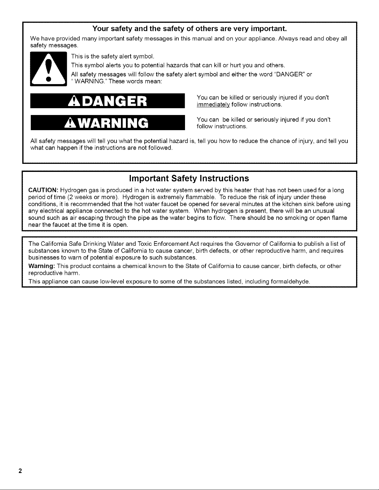
This is the safety alert symbol.
This symbol alerts you to potential hazards that can kill or hurt you and others.
All safety messages will follow the safety alert symbol and either the word "DANGER" or
"WARNING." These words mean:
You can be killed or seriously injured if you don't
immediately follow instructions.
You can be killed or seriously injured if you don't
follow instructions.
All safety messages will tell you what the potential hazard is, tell you how to reduce the chance of injury, and tell you
what can happen if the instructions are not followed.
Important Safety Instructions
CAUTION: Hydrogen gas is produced in a hot water system served by this heater that has not been used for a long
period of time (2 weeks or more). Hydrogen is extremely flammable. To reduce the risk of injury under these
conditions, it is recommended that the hot water faucet be opened for several minutes at the kitchen sink before using
any electrical appliance connected to the hot water system. When hydrogen is present, there will be an unusual
sound such as air escaping through the pipe as the water begins to flow. There should be no smoking or open flame
near the faucet at the time it is open.
The California Safe Drinking Water and Toxic Enforcement Act requires the Governor of California to publish a list of
substances known to the State of California to cause cancer, birth defects, or other reproductive harm, and requires
businesses to warn of potential exposure to such substances.
Warning: This product contains a chemical known to the State of California to cause cancer, birth defects, or other
reproductive harm.
This appliance can cause low-level exposure to some of the substances listed, including formaldehyde.
INSTALLING YOUR WATER HEATER
Consumer Information
This water heater should be installed in accordance
with the local code authority having jurisdiction, the
power company or electric utility, and this installation
manual. In the absence of local code requirements,
follow the regulations set forth in the latest edition of the
National Electric Code, NFPA 70. This is available from
the following:
National Fire Protection Agency
1 Batterymarch Park
Quincy, MA 02269
American National Standards Institute
1430 Broadway
New York, NY 10018
Check your phone listings for the local authorities
having jurisdiction over your installation.
Consumer Responsibilities
This manual has been prepared to acquaint you with
the installation, operation, and maintenance of your
electric water heater and to provide important safety
information in these areas.
We urge you to read all of the instructions thoroughly
before attempting the installation or operation of this
water heater. This manual should be kept for future
reference.
The manufacturer of this water heater will not be liable
for any damages caused by failure to comply with the
installation and operating instructions outlined in this
manual.
If you lack the necessary skills required to properly
install this water heater or you have difficulty following
the instructions, you should not proceed but have a
qualified person perform the installation of this water
heater. Massachusetts code requires this water heater
to be installed in accordance with Massachusetts
Plumbing and Fuel Gas Code 248 CMR section 2.00
and 5.00.
A data plate identifying your water heater can be found
adjacent to the element door. When referring to your
water heater always have the information listed on the
data plate readily available.
Retain your original receipt as proof of purchase.
Unpacking the Water Heater
Removing Packaging Materials
Important: Do not remove any permanent instructions,
labels, or the data label from outside of the water heater
or on the inside of panels.
Remove exterior packaging and place installation
components aside.
Do not remove the envelope bag containing the
water heater literature from the side of the water
heater.
Inspect all parts for damage prior to installation and
start-up.
Completely read all instructions before attempting
to assemble and install this product.
_. Replace this manual inside the envelope bag when
installation is complete.
_. After installation, dispose of packaging material in
the proper manner.
Location Requirements
Site location
Select a location near the center of the water piping
system, tt must be installed indoors and in a vertical
position on a level surface.
The water heater should be located in an area not
subject to freezing temperatures. Water heaters located
in unconditioned spaces (i.e., attics, basements, etc.)
may require the water piping and drain piping to be
insulated to protect against freezing. The drain and
controls must be easily accessible for operation and
service.
Do not use this water heater in conjunction with a spa
or hot tub.
Note: Local codes and requirements in your area may
require the water heater to be installed such that the
bottom element is elevated from the floor at least 18
inches.
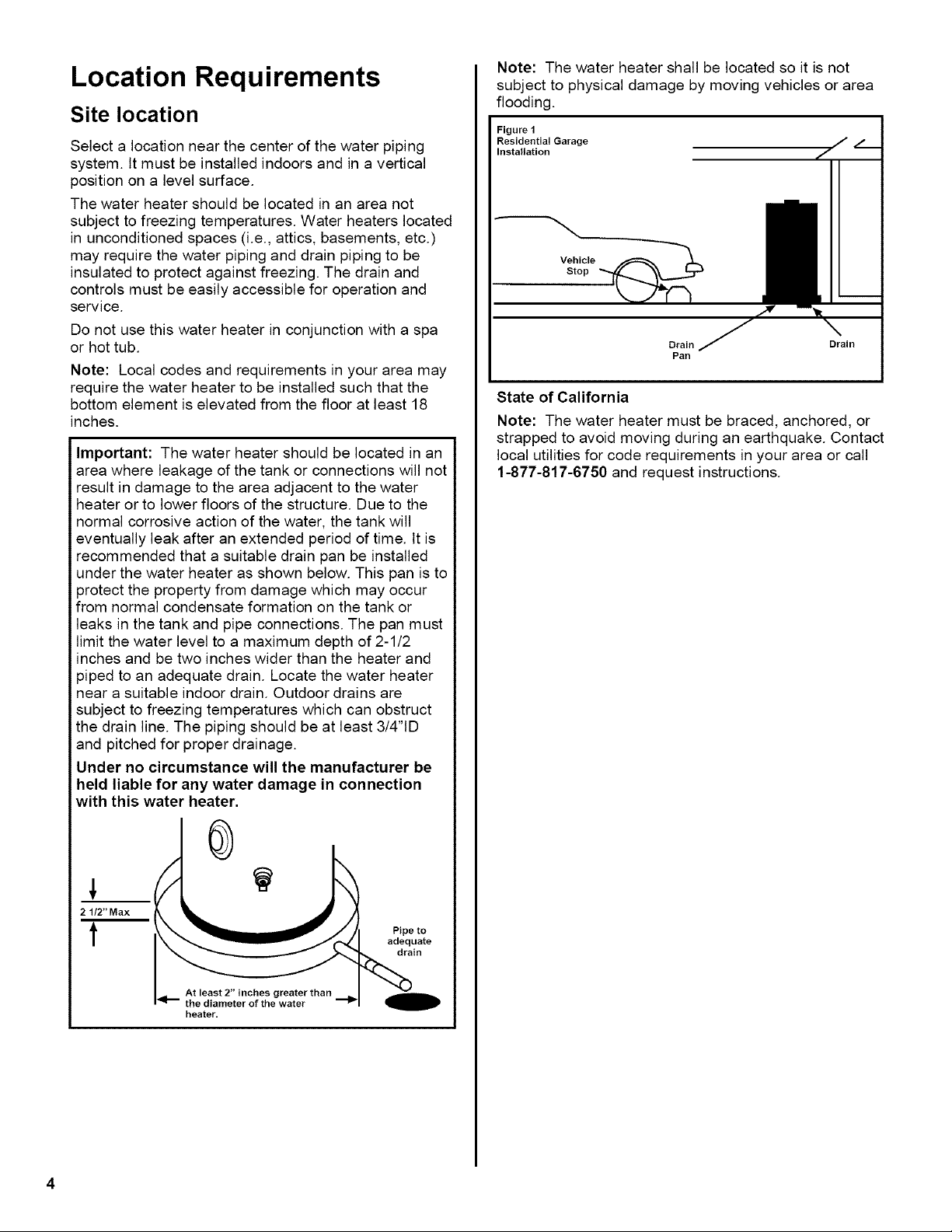
Important: The water heater should be located in an
area where leakage of the tank or connections will not
result in damage to the area adjacent to the water
heater or to lower floors of the structure. Due to the
normal corrosive action of the water, the tank will
eventually leak after an extended period of time. It is
recommended that a suitable drain pan be installed
under the water heater as shown below. This pan is to
3rotect the property from damage which may occur
from normal condensate formation on the tank or
leaks in the tank and pipe connections. The pan must
limit the water level to a maximum depth of 2-1/2
inches and be two inches wider than the heater and
piped to an adequate drain. Locate the water heater
near a suitable indoor drain. Outdoor drains are
subject to freezing temperatures which can obstruct
the drain line. The piping should be at least 3/4"1D
and pitched for proper drainage.
Under no circumstance will the manufacturer be
held liable for any water damage in connection
with this water heater.
0
21/2" Max
t Pipe to
adequate
drain
At least 2" inches greater than
the diameter of the water
heater.
Note: The water heater shall be located so it is not
subject to physical damage by moving vehicles or area
flooding.
Figure 1
Residential Garage
Installation
Vehicle
Stop
Drain Drain
Pan
State of California
Note: The water heater must be braced, anchored, or
strapped to avoid moving during an earthquake. Contact
local utilities for code requirements in your area or call
1-877-817-6750 and request instructions.
Water System Piping
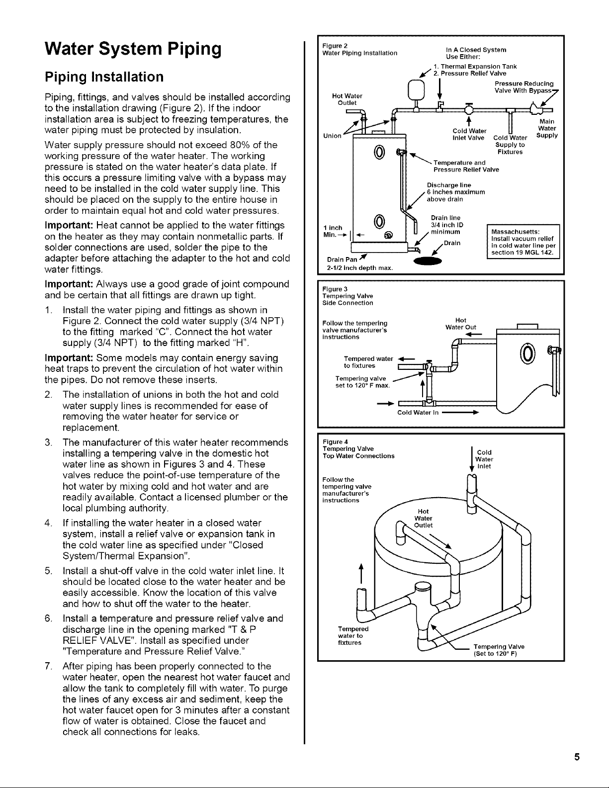
Piping Installation
Piping, fittings, and valves should be installed according
to the installation drawing (Figure 2). If the indoor
installation area is subject to freezing temperatures, the
water piping must be protected by insulation.
Water supply pressure should not exceed 80% of the
working pressure of the water heater. The working
pressure is stated on the water heater's data plate. If
this occurs a pressure limiting valve with a bypass may
need to be installed in the cold water supply line. This
should be placed on the supply to the entire house in
order to maintain equal hot and cold water pressures.
Important: Heat cannot be applied to the water fittings
on the heater as they may contain nonmetallic parts. If
solder connections are used, solder the pipe to the
adapter before attaching the adapter to the hot and cold
water fittings.
Important: Always use a good grade of joint compound
and be certain that all fittings are drawn up tight.
1. Install the water piping and fittings as shown in
Figure 2. Connect the cold water supply (3/4 NPT)
to the fitting marked "C". Connect the hot water
supply (3/4 NPT) to the fitting marked "H".
Important: Some models may contain energy saving
heat traps to prevent the circulation of hot water within
the pipes. Do not remove these inserts.
2. The installation of unions in both the hot and cold
water supply lines is recommended for ease of
removing the water heater for service or
replacement.
3. The manufacturer of this water heater recommends
installing a tempering valve in the domestic hot
water line as shown in Figures 3 and 4. These
valves reduce the point-of-use temperature of the
hot water by mixing cold and hot water and are
readily available. Contact a licensed plumber or the
local plumbing authority.
4. If installing the water heater in a closed water
system, install a relief valve or expansion tank in
the cold water line as specified under "Closed
System/Thermal Expansion".
5. Install a shut-off valve in the cold water inlet line. It
should be located close to the water heater and be
easily accessible. Know the location of this valve
and how to shut off the water to the heater.
.
.
Install a temperature and pressure relief valve and
discharge line in the opening marked "T & P
RELIEF VALVE". Install as specified under
"Temperature and Pressure Relief Valve."
After piping has been properly connected to the
water heater, open the nearest hot water faucet and
allow the tank to completely fill with water. To purge
the lines of any excess air and sediment, keep the
hot water faucet open for 3 minutes after a constant
flow of water is obtained. Close the faucet and
check all connections for leaks.
Figure 2
Water Piping Installation In A Closed System
Use Either:
1 Thermal Expansion Tank
2 Pressure Relief Valve
O _ Pressure Reducing
Valve With Bypas_7Hot Water
Outlet _ I_ _
t 11 Ma,.
• ,L--_C-,---_ II ColdWater U sWuat)_r
Union _ ----------- Inlet Valve Cold Water PP Y
/
Supply to
Fixtures
/ Temperature and
Pressure Relief Valve
Discharge line
6 inches maximum
above drain
Drain line
linch / (_) _ 3/4inch ID l
Min --_ I_-- ,_) U / minimum Massachusetts:
• I| _ / . Install vacuum relief I
/Dram in cold water line per
f ::_ j¢" section 19 MGL 142• /
s J
Drain Pan
2-1/2 inch depth max.
Figure 3
Tempering Valve
Side Connection
Follow the tempering Hot
valve manufacturer's Water Out
instructions _1_
Tempered water
to fixtures
Tempering valve
set to 120 ° F max.
._
Cold Water In
Figure 4
Tempering Valve
Top Water Connections
Follow the
tempering valve
manufacturer's
instructions
Cold
Water
inlet
t
Tempered
water to
fixtures
Tempering Valve
(Set to 120 ° F)
 Loading...