

American Standard UY100R9V4W, UY080R9V3W, DY060R9V3W, DY100R9V4W, UY120R9V5W Installer's Manual
...
18- CD20D3- 18
Installer’s Guide
Upflow / Horizontal and Downflow / Horizontal,
Gas-Fired, Direct Vent, 2-Stage Condensing
Furnaces with Variable Speed Inducer
*UY060R9V3W
*UY080R9V3W
*__First letter may be “A” or “T”
ALL phases of this installation must comply with NATIONAL, STATE AND LOCAL CODES
IMPORTANT — This Document is customer property and is to remain with this unit.
Please return to service information pack upon completion of work.
*UY-R9V-V
*UY100R9V4W
*UY120R9V5W
*DY060R9V3W
*DY080R9V3W
*DY-R9V-V
*DY100R9V4W
*DY120R9V5W
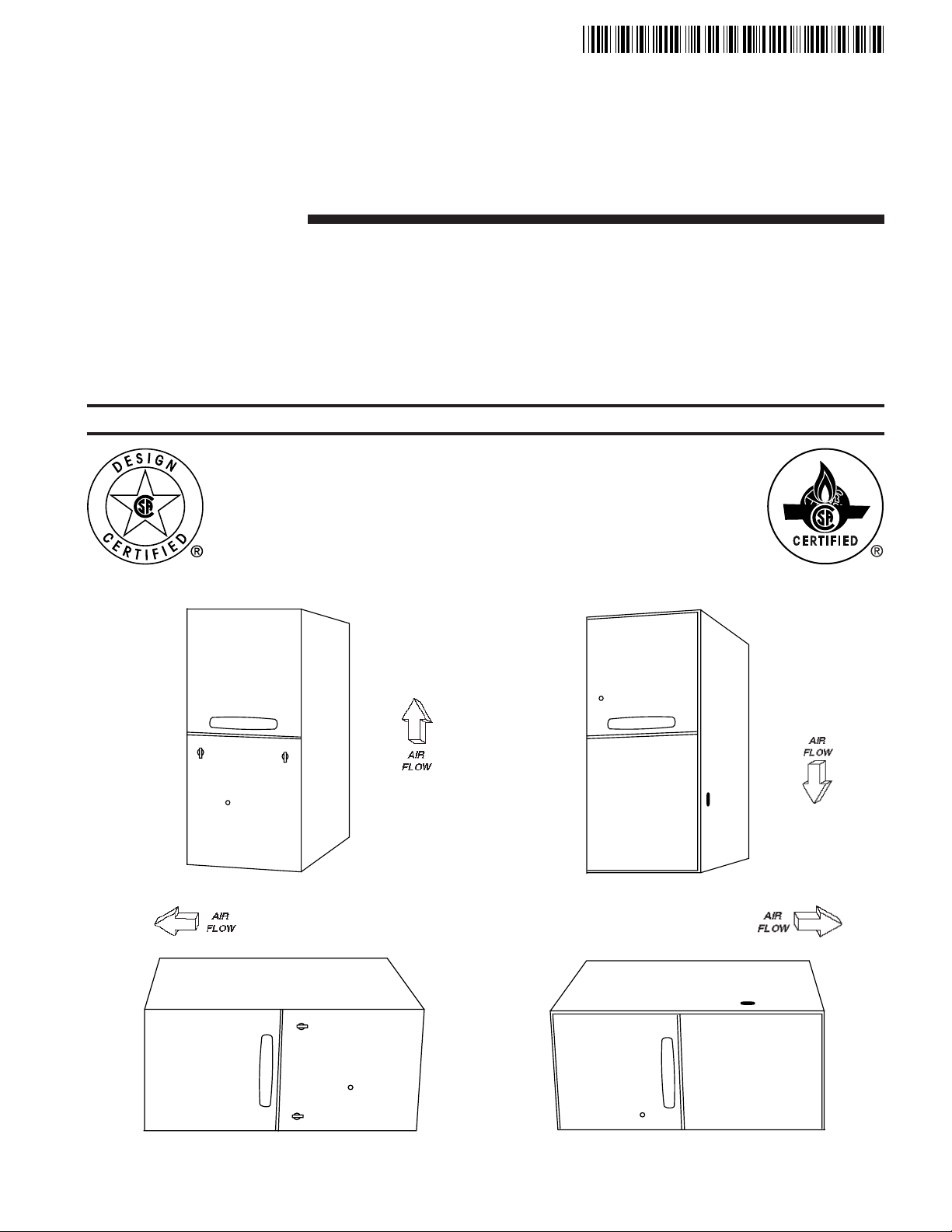
DOWNFLOW
UPFLOW
UPFLOW/HORIZONTAL
DOWNFLOW/HORIZONTAL
A341624P04
Installer’s Guide
SAFETY SECTION
The following safety practices and precautions must be
followed during the installation, servicing, and operation of
this furnace.
1. Use only with the type of gas approved for this furnace.
Refer to the furnace rating plate.
2. Install this furnace only in a location and position as
specified in “Location and Clearances” (page 3), of these
instructions.
3. Provide adequate combustion and ventilation air to the
furnace space as specified in “Air for Combustion and
Ventilation” (pages 7-8), of these instructions.
4. Combustion products must be discharged outdoors.
Connect this furnace to an approved vent system only, as
specified in the “Venting” section (pages 13-22), of these
instructions.
5. Never test for gas leaks with an open flame. Use a
commercially available soap solution made specifically
for the detection of leaks to check all connections, as
specified in “Gas Piping” (page 28), of these instructions.
6. Always install the furnace to operate within the
furnace’s intended temperature-rise range with a duct
system which has an external static pressure within the
allowable range, as specified on the unit rating plate.
Airflow with temperature rise for cfm versus static is
shown in the Service Facts accompanying this furnace.
7. When a furnace is installed so that supply ducts carry
air circulated by the furnace to areas outside the space
containing the furnace, the return air shall also be
handled by a duct(s) sealed to the furnace casing and
terminating outside the space containing the furnace.
8. A gas-fired furnace for installation in a residential
garage must be installed as specified in “Location and
Clearances” section (page 3), of these instructions.
9. The furnace may be used for temporary heating of
buildings or structures under construction only when the
following conditions have been met:
a. The furnace venting system must be complete and
installed per manufacturer’s instructions.
b. The furnace is controlled only by a room thermostat
(no field jumpers).
c. The furnace return air duct must be complete and
sealed to the furnace and clean air filters are in place.
d. The furnace input rate and temperature rise must be
verified to be within nameplate marking.
e. 100% of the furnace combustion air requirement must
come from outside the structure.
f. The furnace return air temperature range is between
55 and 80 degrees Fahrenheit.
g. Clean the furnace, duct work, and components upon
substantial completion of the construction process,
and verify furnace operating conditions including
ignition, input rate, temperature rise and venting,
according to the manufacturer’s instructions.
Safety signal words are used to designate a degree or level
of seriousness associated with a particular hazard. The
signal words for safety markings are DANGER, WARNING,
and CAUTION.
a. DANGER indicates an imminently hazardous situation
which, if not avoided, will result in death or serious injury.
This signal word is limited to the most extreme situations.
b. WARNING indicates a potentially hazardous situation
which, if not avoided, could result in death or serious injury.
c. CAUTION indicates a potentially hazardous situation
which, if not avoided, may result in minor or moderate
injury. It is also used to alert against unsafe practices
and hazards involving only property damage.
!
WARNING
▲
CARBON MONOXIDE POISONING HAZARD
Failure to follow the steps outlined below for each
appliance connected to the venting system being
placed into operation could result in carbon monoxide
poisoning or death.
The following steps shall be followed for each appliance
connected to the venting system being placed into
operation, while all other appliances connected to the
venting system are not in operation:
1. Seal any unused openings in the venting system.
2. Inspect the venting system for proper size and
horizontal pitch, as required in the National Fuel Gas
Code, ANSI Z223.1/NFPA 54 or the CAN/CGA B149
Installation Codes and these instructions. Determine
that there is no blockage or restriction, leakage,
corrosion and other deficiencies which could cause an
unsafe condition.
3. As far as practical, close all building doors and
windows and all doors between the space in which the
appliance(s) connected to the venting system are
located and other deficiencies which could cause an
unsafe condition.
4. Close fireplace dampers.
5. Turn on clothes dryers and any appliance not
connected to the venting system. Turn on any exhaust
fans, such as range hoods and bathroom exhausts, so
they are operating at maximum speed. Do not operate
a summer exhaust fan.
6. Follow the lighting instructions. Place the appliance
being inspected into operation. Adjust the thermostat
so appliance is operating continuously.
7. If improper venting is observed during any of the above
tests, the venting system must be corrected in
accordance with the National Fuel Gas Code,
ANSI Z221.1/NFPA 54 and/or CAN/CGA B149
Installation Codes.
8. After it has been determined that each appliance
connected to the venting system properly vents where
tested as outlined above, return doors, windows,
exhaust fans, fireplace dampers and any other gas-fired
burning appliance to their previous conditions of use.
!
WARNING
▲
FIRE OR EXPLOSION HAZARD
Failure to follow the safety warnings exactly could result in
serious injury, death or property damage.
Improper servicing could result in dangerous operation,
serious injury, death, or property damage.
!
CAUTION
▲
To prevent shortening its service life, the furnace should
not be used as a “Construction Heater” during the finishing
phases of construction until the requirements listed in item
9, a-g of the safety section of this publication have been
met. Condensate in the presence of chlorides and fluorides from paint, varnish, stains, adhesives, cleaning
compounds, and cement create a corrosive condition
which may cause rapid deterioration of the heat exchanger.
© 2004 American Standard Inc. All Rights Reserved 18-CD20D3-18

Installer’s Guide
GENERAL INSTALLATION INSTRUCTIONS
The manufacturer assumes no responsibility for equipment
installed in violation of any code or regulation.
It is recommended that Manual J of the Air Conditioning
Contractors Association (ACCA) or A.R.I. 230 be followed in
estimating heating requirements. When estimating heating
requirements for installation at altitudes above 2000 ft.,
remember the gas input must be reduced (See GAS INPUT
ADJUSTMENT).
Material in this shipment has been inspected at the
factory and released to the transportation agency
without known damage. Inspect exterior of carton for
evidence of rough handling in shipment. Unpack
carefully after moving equipment to approximate
location. If damage to contents is found, report the
damage immediately to the delivering agency.
Codes and local utility requirements governing the installation of gas fired equipment, wiring, plumbing, and flue
connections must be adhered to. In the absence of local
codes, the installation must conform with latest edition of the
National Fuel Gas Code ANSI Z223.1 • National Installation
Code, CAN/CGA B149.1. The latest code may be obtained
from the American Gas Association Laboratories,
8501 E. Pleasant Valley Rd., Cleveland, Ohio 44131.
These furnaces have been classified as CATEGORY IV
furnaces in accordance with latest edition of ANSI Z21.47
standards • CAN/CGA 2.3. Category IV furnaces operate
with positive vent static pressure and with a flue loss less
than 17 percent. These conditions require special venting
systems, which must be gas tight and water tight. These
Category IV Direct Vent furnaces are approved for installation in Manufactured/Mobile housing when used with
BAYMFGH100A.
LOCATION AND CLEARANCES
The location of the furnace is normally selected by the
architect, the builder, or the installer. However, before the
furnace is moved into place, be sure to consider the following
requirements:
1. Is the location selected as near the chimney or vent and
as centralized for heat distribution as practical?
2. Do all clearances between the furnace and enclosure
equal or exceed the minimums stated in Clearance Table
on the Outline Drawings.
3. Is there sufficient space for servicing the furnace and
other equipment? A minimum of 24 inches front accessibility to the furnace must be provided. Any access door
or panel must permit removal of the largest component.
4. Are there at least 3 inches of clearance between the
furnace combustion air openings in the front panel and
any closed panel or door provided?
5. Are the ventilation and combustion air openings large
enough and will they remain unobstructed? If outside
air is used, are the openings set above the highest snow
accumulation level? (See the Air for Combustion and
Ventilation section)
6. Allow sufficient height in supply plenum above the furnace to provide for cooling coil installation, if the cooling
coil is not installed at the time of this furnace installation.
7. A furnace shall be installed so electrical components are
protected from water.
8. If the furnace is installed in a residential garage, it
must be installed so that the burners, and the ignition
source are located not less than 18 inches above the floor
and the furnace must be located or protected to avoid
physical damage from vehicles.
Contents
Installation Instructions 3
General Installation Instructions 3
Location and Clearances 3
Outline Drawing 4-5
Upflow Installation 6
Downflow Installations 6
Horizontal Installation 6
Air for Combustion and Ventilation 7
Duct Connections 8
Return Air Filters 9
General Venting Information 13
Venting Materials 15
High Altitude Derate 16
Horizontal Venting Through the Wall 17
Downward Venting 18
Venting Through the Roof 22
Venting Routed Through a Masonry Chimney 23
Electrical Connections 24
Field Wiring Diagrams 24-26
Condensate Drain Instructions 26
Gas Piping 28
Combustion and Input Check 29
Start-up and Adjustment 31
Preliminary Inspections 31
Lighting Instructions 31
Sequence of Operation 32
Control and Safety Switch Adjustments 32
Airflow Adjustment 32
Abnormal Conditions 33
IFC Error Flash Codes 35
Fault Code Recovery 35
IMPORTANT:
The furnace must be installed level. The only allowable variation
would be slightly to the left and/or forward in upflow installations
or slightly toward the front in horizontal installations. This is
necessary for proper condensate drainage.
!
CAUTION
▲
Do not install the furnace in a corrosive or contaminated
atmosphere. Failure to follow this warning could result in
early equipment failure.
!
WARNING
▲
Do not install the furnace directly on carpeting, tile or other
combustible material other than wood flooring. For vertical
downflow application, subbase (BAYBASE205) must be
used between the furnace and combustible flooring. When
the downflow furnace is installed vertically with a cased
coil, a subbase is not required.
18-CD20D3-18 3
Installer’s Guide
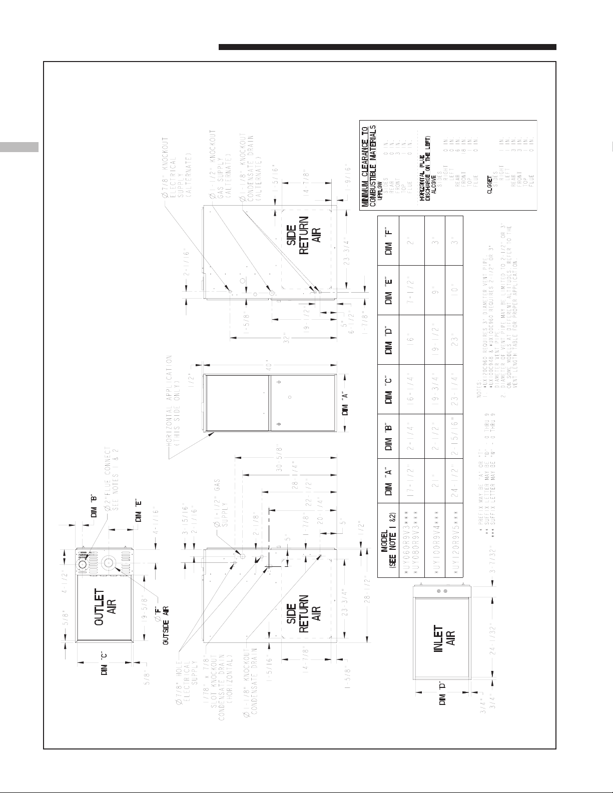
From Dwg. 21C341884 Rev. 1
(ALL DIMENSIONS ARE IN INCHES)
*UY-R9V-W OUTLINE DRAWING
4 18-CD20D3-18
Installer’s Guide
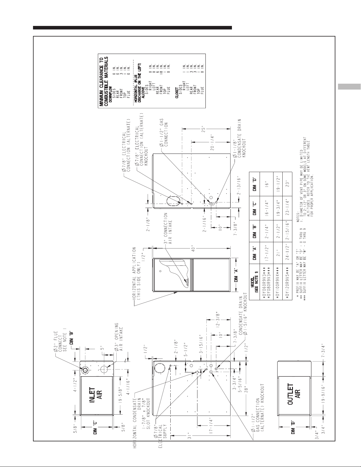
From Dwg. 21C341885 Rev. 1
(ALL DIMENSIONS ARE IN INCHES)
*DY-R9V-W DOWNFLOW / HORIZONTAL OUTLINE DRAWING
18-CD20D3-18 5
Installer’s Guide
6
6
6
6
6
6
6
6
6
6
6
6
6
6
6
6
6
6
6
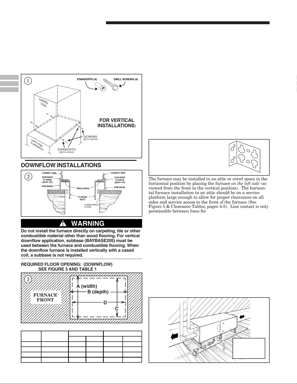
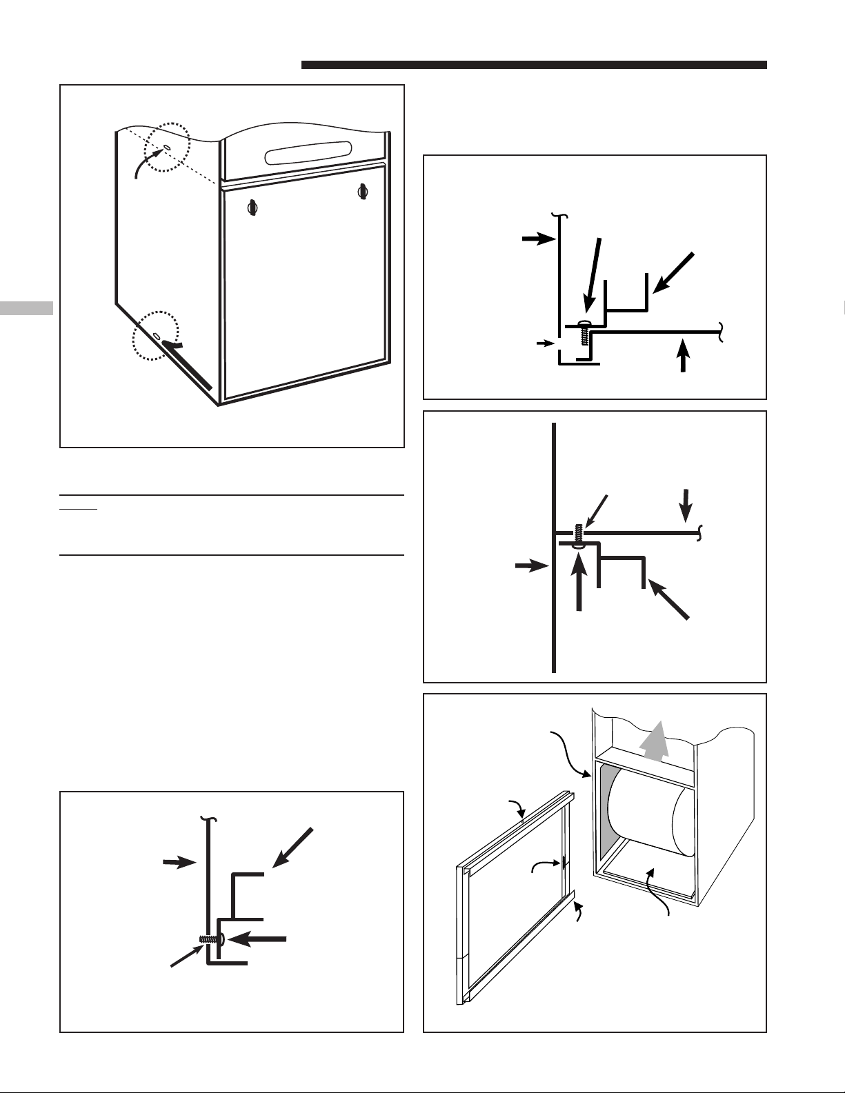
UPFLOW INSTALLATION
Standoffs and screws (See Figure 1) are included with the
cased coils for attachment to the furnace. There are clearance
alignment holes near the bottom of the coil wrapper. Drill
screws are used to engage the furnace top flanges. The
standoff is inserted into the cabinet alignment hole. The drill
screws are inserted through the standoffs then screwed into
the furnace flange. The coil is always placed downstream of
the furnace airflow.
STANDOFFS (4)
DRILL SCREWS (4)
1
CASED
COIL
FOR VERTICAL
INSTALLATIONS:
SCREWS
UPFLOW
FURNACE
STANDOFFS
(BOTH SIDES)
DOWNFLOW INSTALLATIONS
(BOTH SIDES)
HORIZONTAL INSTALLATION
The coil and furnace must be fully supported when used in
the horizontal position. It is always recommended that an
auxiliary drain pan be installed under a horizontally installed evaporator coil or 90% gas furnace. Connect the
auxiliary drain line to a separate drain line (no trap is
needed in this line).
Three brackets (with screws) are included with downflow
furnaces for installation to stabilize and secure the furnace
and TXC cased coil in the horizontal position. See
Figure 4. The coil is placed downstream of the furnace, with
the apex of the coil pointing in the direction of the airflow for
horizontal installation. The cased coil is secured to the
furnace and both the furnace and the cased coil must be
properly supported. The brackets mount using the rear
screws on the coil case and use the screws provided to secure
the bracket to the furnace. The remaining bracket is placed
as close to center as possible (horizontally) between the coil
case front and the furnace bottom channel (for downflow/
horizontal furnace). Use four of the screws provided to
secure the bracket. The upflow furnace, converted to horizontal, aligns and attaches the TXC coil as in Figure 1. However,
the coil requires additional support.
4
CASED COIL CONNECTION
BRACKET FOR DOWNFLOW
FURNACE IN HORIZONTAL
DOWNFLOW ONLY
2
!
WARNING
▲
Do not install the furnace directly on carpeting, tile or other
combustible material other than wood flooring. For vertical
downflow application, subbase (BAYBASE205) must be
used between the furnace and combustible flooring. When
the downflow furnace is installed vertically with a cased
coil, a subbase is not required.
REQUIRED FLOOR OPENING: (DOWNFLOW)
2345678901234567890123456789012123456789012345
2345678901234567890123456789012123456789012345
2345678901234567890123456789012123456789012345
2345678901234567890123456789012123456789012345
2345678901234567890123456789012123456789012345
2345678901234567890123456789012123456789012345
2345678901234567890123456789012123456789012345
2345678901234567890123456789012123456789012345
2345678901234567890123456789012123456789012345
2345678901234567890123456789012123456789012345
2345678901234567890123456789012123456789012345
2345678901234567890123456789012123456789012345
2345678901234567890123456789012123456789012345
2345678901234567890123456789012123456789012345
2345678901234567890123456789012123456789012345
2345678901234567890123456789012123456789012345
2345678901234567890123456789012123456789012345
2345678901234567890123456789012123456789012345
2345678901234567890123456789012123456789012345
SEE FIGURE 3 AND TABLE 1
3
FURNACE
FRONT
A (width)
B (depth)
D
C
The furnace may be installed in an attic or crawl space in the
horizontal position by placing the furnace on the left side (as
viewed from the front in the vertical position). The horizontal furnace installation in an attic should be on a service
platform large enough to allow for proper clearances on all
sides and service access to the front of the furnace (See
Figure 5 & Clearance Tables, pages 4-5). Line contact is only
permissible between lines formed by intersections of the top
and two sides of the furnace casing and building joists, studs,
or framing.
The furnace may be placed horizontally in a crawl space on a
pad or other noncombustible material which will raise the
unit for sufficient protection from moisture. The furnace
must be supported at both ends and the middle when
installed horizontally. The furnace must also be
elevated approximately 4-6 inches to allow clearance
for the condensate drain to exit the cabinet in the
horizontal position.
The horizontal furnace may also be suspended from the joists
using 3/8" all-thread rods with pieces of angle iron underneath the furnace to form a hanging rack at both ends and
the midpoint. The rods need to be of sufficient length to
allow for proper clearances from combustible materials. The
angle iron needs to be at least 32" in length to allow for
access to service panels.
5
TABLE 1
CABINET
WIDTH
RETURN
DUCT WIDTH
FLOOR OPENING PLENUM OPENING
"A" "B" "C" "D"
14-1/2" 13-1/4" 13-5/8" 20-1/8" 12-5/8" 19-3/8"
17-1/2" 16-1/4" 16-5/8" 20-1/8" 15-5/8" 19-3/8"
21" 19-3/4" 20-1/8" 20-1/8" 19-1/8" 19-3/8"
24-1/2" 23-1/4" 23-5/8" 20-1/8" 22-5/8" 19-3/8"
6 18-CD20D3-18
UPFLOW/
HORIZONTAL
SHOWN WITH
DIRECT VENT
6
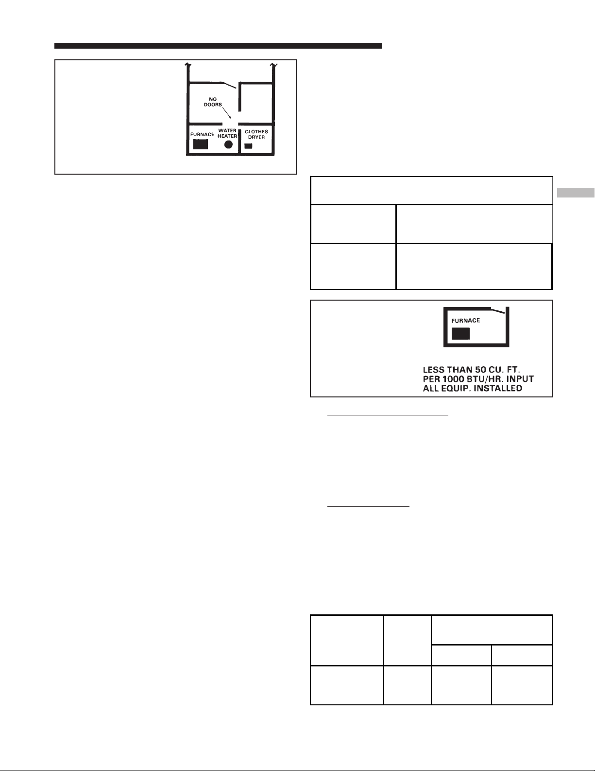
50 CU. FT. OR MORE
PER 1000 BTU/HR. INPUT
ALL EQUIP. INSTALLED
UNCONFINED
Installer’s Guide
Unconfined space is defined in Figure 6. These spaces may
have adequate air by infiltration to provide air for combustion and ventilation. Buildings with tight construction (for
example, weather stripping, heavily insulated, caulked, vapor
barrier, etc.), may need additional air to be provided as
described for confined space.
Confined spaces are installations with less than 50 cu. ft. of
space per 1000 BTU/hr input from all equipment installed.
Air for combustion and ventilation requirements can be
supplied from inside the building as in Figure 8 or from the
outdoors, as in Figure 9.
AIR FOR COMBUSTION AND VENTILATION
If these furnaces are installed in a nondirect vent capacity
then the adequate flow of combustion and ventilating air
must not be obstructed from reaching the furnace. Air
openings provided for combustion air must be kept free of
obstructions which restrict the flow of air. Airflow restrictions affect the efficiency and safe operation of the furnace.
Keep this in mind should you choose to remodel or change
the area which contains your furnace. Furnaces must have a
free flow of air for proper performance.
Provisions for combustion and ventilation air shall be made
in accordance with latest edition of Section 5.3, Air for
Combustion and Ventilation, of the National Fuel Gas Code,
ANSI Z223.1 — CAN/CGA B149.1 or applicable provisions of
the local building codes. Special conditions created by
mechanical exhausting of air and fireplaces must be considered to avoid unsatisfactory furnace operation.
OUTSIDE AIR IS RECOMMENDED
The use of indoor air for most applications is acceptable,
unless there is the presence of corrosive chemicals or
contamination. Certain types of installation will require
the use of outside air for combustion.
The following types of installations will require use of
OUTDOOR AIR for combustion, due to chemical exposures:
* Commercial buildings
* Buildings with indoor pools
* Furnaces installed in “confined” laundry rooms
* Furnaces installed in “confined” hobby or craft rooms
* Furnaces installed near chemical storage areas.
Exposure to the following substances in the combustion air
supply will also require OUTDOOR AIR for combustion:
* Permanent wave solutions
* Chlorinated waxes and cleaners
* Chlorine based swimming pool chemicals
* Water softening chemicals
* Deicing salts or chemicals
* Carbon Tetrachloride
* Halogen type refrigerants
* Cleaning solvents (such as perchloroethylene)
* Printing inks, paint removers, varnish, etc.
* Hydrochloric acid
* Cements and glues
* Antistatic fabric softeners for clothes dryers
* Masonry acid washing materials
Furnace locations may be in a “confined space” or an
“unconfined space”.
7
MAXIMUM BTUH
MINIMUM AREA IN SQUARE FEET
FOR UNCONFINED SPACE INSTALLATIONS
FURNACE
MINIMUM AREA IN SQUARE FEET
INPUT RATING
60,000
80,000
100,000
120,000
WITH 8 FT. CEILING
OF UNCONFINED SPACE
375
500
625
875
8
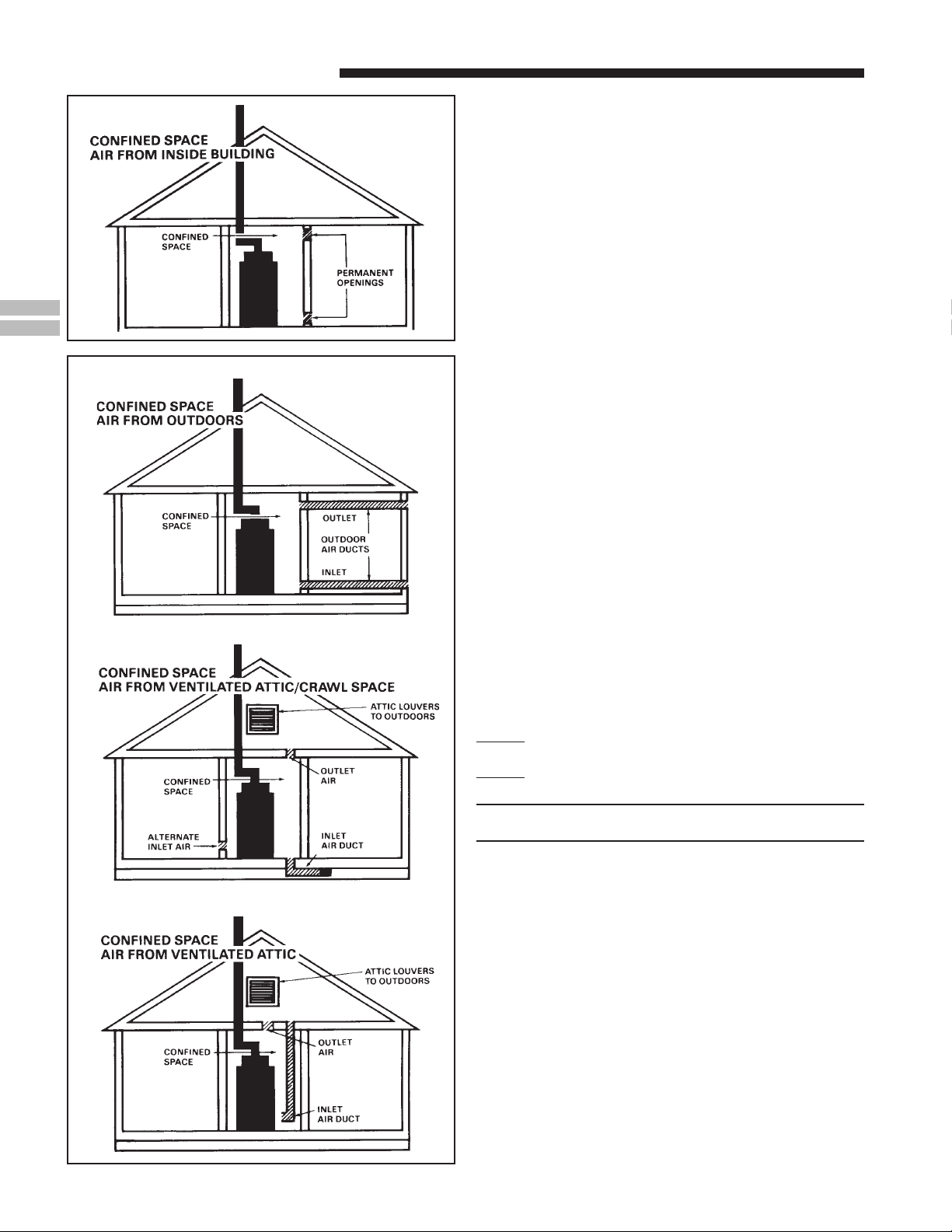
CONFINED
SPACE
All air from inside the building as in Figure 9: The
1.
confined space shall be provided with two permanent
openings communicating directly with an additional
room(s) of sufficient volume so that the combined volume
of all spaces meets the criteria for an unconfined space.
The total input of all gas utilization equipment installed
in the combined space shall be considered in making this
determination. Refer to Table 2 for minimum open areas
requirements.
All air from outdoors as in Figure 10: The confined space
2.
shall be provided with two permanent openings, one
commencing within 12 inches of the top and one commencing within 12 inches of the bottom of the enclosure.
The openings shall communicate directly, or by ducts,
with the outdoors or spaces (crawl or attic) that freely
communicate with the outdoors. Refer to Table 2, for
minimum open areas requirements.
TABLE 2
MINIMUM FREE AREA IN SQUARE INCHES
EACH OPENING (FURNACE ONLY)
Furnace
Maximum
BTUH/INPUT
Rating
60,000
80,000
100,000
120,000
Air
From
Inside
100
100
100
120
Air From Outside
Vertical
Duct
15
20
25
30
Horizontal
Duct
30
40
50
60
18-CD20D3-18 7
Installer’s Guide
9
0
DUCT CONNECTIONS
Air duct systems should be installed in accordance with
standards for air conditioning systems, National Fire Protection Association Pamphlet No. 90. They should be sized in
accordance with ACCA Manual D or whichever is applicable.
Central furnaces, when used in connection with cooling units,
shall be installed in parallel or on the upstream side of the
cooling coil to avoid condensation in the heat exchanger. With
a parallel flow arrangement, the dampers or other means
used to control flow of air shall be adequate to prevent chilled
air from entering the furnace, and if manually operated,
must be equipped with means to prevent operation of either
unit unless the damper is in full heat or cool position.
On any job, flexible connections of nonflammable material
may be used for return air and discharge connections to prevent transmission of vibration. Though these units have been
specifically designed for quiet, vibration free operation, air
ducts can act as sounding boards and could, if poorly installed,
amplify the slightest vibration to the annoyance level.
When the furnace is located in a utility room adjacent to the
living area, the system should be carefully designed with
returns to minimize noise transmission through the return
air grille. Although these furnaces are designed with large
blowers operating at moderate speeds, any blower moving a
high volume of air will produce audible noise which could be
objectionable when the unit is located very close to a living
area. It is often advisable to route the return air ducts under
the floor or through the attic. Such design permits the
installation of air return remote from the living area
(i.e. central hall).
When the furnace is installed so that the supply ducts carry
air circulated by the furnace to areas outside the space
containing the furnace, the return air shall also be handled
by a duct(s) sealed to the furnace and terminating outside
the space containing the furnace.
RETURN AIR DUCT SYSTEMS
Where there is no complete return duct system, the
return connection must be run full size from the
furnace to a location outside the utility room, basement, attic, or crawl space.
Do Not install return air through the back of the furnace
cabinet.
Do Not install return air through the side of the furnace
cabinet on horizontal applications.
NOTE:
Minimum return air temperature is 50° F.
All return air duct systems should provide for installation of
return air filters.
1. Set the furnace in place.
2. For upflow side return installations, remove the insulation
around the opening in the blower compartment.
3. The side panels of the upflow furnace include locating
notches that are used as guides for cutting an opening
for return air, refer to Figure 11 and the outline drawing
on page 4 for duct connection dimensions for various
furnaces.
4. If a 3/4" flange is to be used for attaching the air inlet
duct, add to cut where indicated by dotted lines in
Figure 11. Cut corners diagonally and bend outward to
form flange.
5. If flanges are not required, and a filter frame is installed,
cut between locating notches (See Figure 11).
6. The bottom panel of the upflow furnace must be removed for bottom return air.
8 18-CD20D3-18
Installer’s Guide
Remove the filter and lay the furnace on its back. Remove
the two 1/4" hex screws securing the bottom front channel
to the cabinet. Lower the front edge of the bottom front
channel and pull forward to remove the channel. The
bottom return air panel will now easily slide out of the
cabinet. Reinstall the bottom front channel and filter for
upflow bottom return installations.
7. The filter retainer is factory supplied for upflow bottom
return. Use the filter retainer on side or bottom if filter
is to be used within the furnace cabinet on upflow only
installations.
8. The horizontal installation of the upflow furnace
requires an external filter section. Do NOT use the
bottom return filter within the furnace. Filter kits
are available for horizontal applications.
9. Connect duct work to furnace. See Outline Drawing for
supply and return duct size and location. Flexible duct
connectors are recommended to connect both supply and
return air ducts to the furnace. If only the front of the
furnace is accessible, it is recommended that both supply
and return air plenums are removable.
RETURN AIR FILTERS
TYPICAL UPFLOW RETURN AIR FILTER INSTALLATIONS
Filters are factory supplied for these furnaces. These furnaces require high velocity type air filters. The filters may be
located within the furnace blower compartment for UPFLOW
furnaces in either a BOTTOM or SIDE (left side or right side)
return air inlet. Some filters may need to be trimmed for
side or bottom filter use.
TABLE 3
MODELS
NUMBERS
*UY060R9V3
*UY080R9V3
*UY100R9V4 21" 1 - 20" X 25" X 1"
*UY120R9V5 24-1/2" 1 - 24" X 25" X 1"
* First letter may be "A" or "T"
** NOTE - On 5 ton airflow models, if the airflow requirement
exceeds 1800 CFM, these models will require return air openings
and filters on both sides; OR 1 side and the bottom; OR just the
bottom.
CABINET
WIDTH
17-1/2" 1 - 17" X 25" X 1"
FILTER
QTY & SIZE
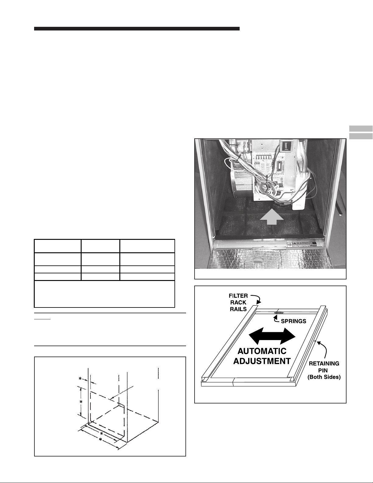
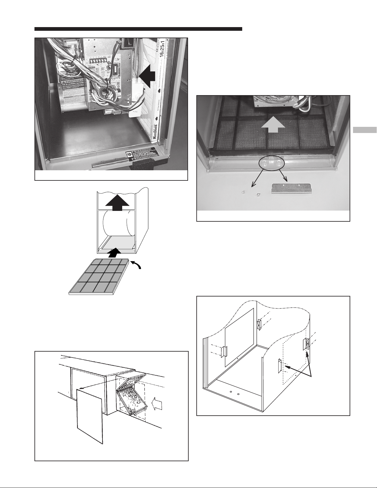
The upflow furnace blower door has a hinge at the bottom
which allows the door to tilt forward for filter replacement
without the door being removed (See Figure 12). The furnace
filter in the bottom or side configuration can be removed by
simply turning the two latches on the blower door and tilting
the door forward.
The filter rails are spring loaded for automatic adjustment to
allow standard size, locally obtainable replacement filters.
The filter rack itself slides to adjust to the required width
needed for bottom or side return (See Figure 13).
BOTTOM FILTER RACK INSTALLATION
With the filter removed, the filter rack is compressed and
then inserted into the bottom of the furnace. The retaining
screw/pin on each side inserts into engagement holes at the
bottom of the furnace cabinet side.
w
Airflow
Blower Door Hinge and Bottom Filter Rack Installation
e
NOTE:
On upflow 5 ton airflow models, if the airflow requirement
exceeds 1800 CFM, these models will require return air
openings and filters on both sides; OR 1 side and the
bottom; OR just the bottom.
q
LOCATING
NOTCHES PROVIDED FOR SIDE
RETURN CUTOUT
SEE OUTLINE DRAWING
*
18-CD20D3-18 9
UPFLOW FURNACE ONLY
CUT OUT FOR
SIDE FILTER
Filter Rack Assembly
FRONT
of Furnace
Installer’s Guide
r
the blower deck and the lower pin/screw rests against
the side of the bottom panel. See Figures 15-19.
f. Reinstall the furnace filter on the side inserting the
chamfer end first.
Blower Deck
Engagement
Hole
VIEW
ENGAGEMENT
HOLE DETAIL
(Typical both sides
and blower deck)
FILTER RACK INSTALLATION FOR SIDE RETURN AIR
ON UPFLOW FURNACES (Left or Right)
NOTE:
The filter rack installation is not allowed for right side
return on the following models: *UY060R9V3 &
*UY080R9V3.
If side air return is desired, it is necessary to move the filter
rack from the bottom of the furnace and reinstall it on the
side. The following instructions should be used:
a. Open or remove the blower door.
b. Remove the filter.
c. Compress the filter rack to disengage the retaining
pins/screws from the furnace sides and slide the filter
rack out.
d. Leave the bottom panel in place.
e. After the side cutout is made following the directions
in the “Return Air Duct Connections” section on
pages 8 and 9, compress the filter rack and reinstall
in the side of the furnace. Confirm that the upper
retaining pin/screw locks into the engagement hole in
t
Furnace
Filter
Rack
Cabinet
Side
y
Furnace
Cabinet
Side
Engagement Hole
For
Filter Rack
Installation With
Bottom Return
u
BLOWER
DECK
Furnace
Cabinet
Side
i
(Both Sides)
SIDE
CUTOUT
RETAINING
PIN
BOTTOM ENGAGEMENT
Filter Rack
Retaining
Screw/Pin
Bottom Panel
Engagement Hole
For
Filter Rack
Installation With
Side
Return
Filter Rack
Retaining
Screw/Pin
Airflow
SPRINGS
Filter
Rack
Furnace
Blower
Deck
Filter
Rack
Assembly
Filter Rack
Retaining
Screw/Pin
Engagement Hole
For
Filter Rack
Installation With
Bottom Return
10 18-CD20D3-18
Typical Upflow Left Side Return Filter Rack Installation
FILTER
RACK
RAILS
BOTTOM
PANEL
INSTALLED
REAR
SIDE
CUT-OUT
ALTERNATE FILTER
CLIPS LOCATION
o
Airflow
Typical Upflow Right Side Return Filter Rack Installation
Installer’s Guide
BLOWER DOOR / HINGE REMOVAL
If clearance or other problems create a problem in using the
tilting door, the blower door hinge may be removed without
creating any problems with the seal of the furnace. To
remove the blower door, tilt the door forward 2 to 3 inches
and pull up. To remove the tilt feature, simply remove the
lower hinge as shown in Figure 20. The bottom of the blower
door will catch in the bottom of the furnace front channel for
door replacement.
a
Airflow
Airflow
CHAMFER
END OF
FILTER GOES
INTO FILTER
RACK FIRST
RETURN AIR FILTERS FOR UPFLOW FURNACE IN
HORIZONTAL CONFIGURATION
When the Upflow Furnace is installed in the horizontal
configuration, the return air filters must be installed exterior
to the cabinet. Remote filter grilles may be used for homeowner convenience or the filters may be installed in the duct
work upstream of the furnace. See Figure 20.
p
Airflow
Door Hinge Removed
ALTERNATE UPFLOW FILTER
CLIP / BRACKET INSTALLATION
1. Determine the location to be used. The furnace cabinet
has dimples for location of the alternate furnace clips
(Side return only). Pre-drill clearance holes with a
3/16" drill. Bottom return holes are pre-drilled.
2. Install the clips in front and rear of the desired location
using the screws provided. The filter clip with the leaf
spring mounts in the rear of the cabinet.
s
TYPICAL RETURN AIR FILTER INSTALLATION IN
UPFLOW MODEL IN HORIZONTAL POSITION
18-CD20D3-18 11
 Loading...