

Installation
Operation
Maintenance
Split System Cooling or
Heat Pump Air Handler
7½ - 20 Tons
Model TWE
Models (60 Hz) Models (50 Hz)
TWE060A***E TWE050AD**E
TWE060B***E TWE075AD**E
TWE090A***E TWE100AD**E
TWE090B***E TWE100BD**E
TWE120A***F TWE155BD**E
TWE120B***E TWE200BD**F
TWE180B***E
TWE240B***F
October 2006 TWE-SVX03C-EN

Preface and Warnings and Cautions
Literature Change History
TWE-SVX03A-EN (June 2003)
Implemented Global Graphics format
to IOM.
TWE-SVX03B-EN (April 2005)
Added capacitor discharge warning.
TWE-SVX03C-EN (September 2006)
Model number for 200 and 240 went
to an "F".
TWE-SVX03C-EN (October 2006)
Updated 200 and 240 unit
dimensions.
Note: One copy of this document
ships inside the control panel
of each unit and is customer
property. It must be retained
by the unit’s maintenance
personnel.
This booklet describes proper
installation, operation, and
maintenance procedures for air
cooled systems. By carefully
reviewing the information within this
manual and following the
instructions, the risk of improper
operation and/or component damage
will be minimized.
It is important that periodic
maintenance be performed to help
assure trouble free operation. A
maintenance schedule is provided at
the end of this manual. Should
equipment failure occur, contact a
qualified service organization with
qualified, experienced HVAC
technicians to properly diagnose and
repair this equipment.
Note: All phases of this installation
must comply with the
NATIONAL, STATE & LOCAL
CODES. In addition to local
codes, the installation must
conform with National
Electric Code -ANSI/NFPA
NO. 70 LATEST REVISION.
Note: Do Not release refrigerant
to the atmosphere! If
adding or removing
refrigerant is required, the
service technician must
comply with all federal,
state, and local laws.
Warnings and Cautions
Notice that warnings and cautions
appear at appropriate intervals
throughout this manual. Warnings
are provided to alert installing
contractors to potential hazards that
could result in personal injury or
death, while cautions are designed to
alert personnel to conditions that
could result in equipment damage.
Your personal safety and the proper
operation of this machine depend
upon the strict observance of these
precautions.
NOTICE:
Warnings and Cautions appear at
appropriate sections throughout this
manual. Read these carefully.
WARNING
Indicates a potentially hazardous
situation which, if not avoided, could
result in death or serious injury.
CAUTION
Indicates a potentially hazardous
situations which, if not avoided, may
result in minor or moderate injury. It
may also be used to alert against
unsafe practices.
CAUTION
Indicates a situation that may result
in equipment or property-damageonly accidents.
© 2006 American Standard Inc. All rights reserved TWE-SVX03C-EN

Contents
Model Number Description . . . . . . . . . . . . . . . . . . . . . . . . . . . . . . . . . . . . . . . . . . 4
General Information . . . . . . . . . . . . . . . . . . . . . . . . . . . . . . . . . . . . . . . . . . . . . . . . . 5
Installation Checklist . . . . . . . . . . . . . . . . . . . . . . . . . . . . . . . . . . . . . . . . . . . . . . . . . 5
Unit Inspection . . . . . . . . . . . . . . . . . . . . . . . . . . . . . . . . . . . . . . . . . . . . . . . . . . . . . 5
Inspection Checklist . . . . . . . . . . . . . . . . . . . . . . . . . . . . . . . . . . . . . . . . . . . . . . . . . 5
Unit Dimensions . . . . . . . . . . . . . . . . . . . . . . . . . . . . . . . . . . . . . . . . . . . . . . . . . . . . 6
Installation . . . . . . . . . . . . . . . . . . . . . . . . . . . . . . . . . . . . . . . . . . . . . . . . . . . . . . . . 10
Recommended t’stat wire size . . . . . . . . . . . . . . . . . . . . . . . . . . . . . . . . . . . . . . . . 14
Field Wiring . . . . . . . . . . . . . . . . . . . . . . . . . . . . . . . . . . . . . . . . . . . . . . . . . . . . . . . 15
Field Wiring Outdoor/Indoor . . . . . . . . . . . . . . . . . . . . . . . . . . . . . . . . . . . . . . . . . . 22
Warranty . . . . . . . . . . . . . . . . . . . . . . . . . . . . . . . . . . . . . . . . . . . . . . . . . . . . . . . . . 27
TWE-SVX03C-EN 3

Model Number Description
TWE 090 A 1 00 E A
123 456 7 8 9 10 11 12
Model Number Description
All products are identified by a
multiple-character model number
that precisely identifies a particular
type of unit. An explanation of the
alphanumeric identification code is
provided. Its use will enable the
owner/operator, installing
contractors, and service engineers to
define the operation, specific
components, and other options for
any specific unit.
When ordering replacement parts or
requesting service, be sure to refer
to the specific model number, serial
number, and DL number (if
applicable) stamped on the unit
nameplate.
DIGITS 1-3: PRODUCT TYPE
TWE = Split System Heat Pump/
Cooling Air Handler
DIGITS 4-6: NOMINAL GROSS
COOLING CAPACITY (MBh)
060 = 5 Tons
090 = 7½ Tons
120 = 10 Tons
150 = 12½ Tons
180 = 15 Tons
240 = 20 Tons
DIGIT 7: MAJOR DEVELOPMENT
SEQUENCE
A = Single
B = Dual
DIGIT 8: ELECTRICAL
CHARACTERISTICS
1 = 208-230/60/1
3 = 208-230/60/3
4 = 460/60/3
W = 575/60/3
D = 380-415/50/3
K = 380/60/3
DIGITS 9, 10: FACTORY
INSTALLED OPTIONS
00 = Packed Stock
DIGITS 11: MINOR DESIGN
SEQUENCE
Current Design Sequence
DIGITS 12: SERVICE DIGIT
A = First
4 TWE-SVX03C-EN

General Information
General
This manual covers installation of
the TWE050, 060, 075, 090,100 and
120A single circuit air handlers and
TWE060, 075, 090, 100, 120, 155, 180,
200 and 240B dual circuit air
handlers. These air handler models
incorporate a single slab coil
assembly, improved application
flexibility, servicing, maintenance
accessibility and an improved
accessory line. They are fully
convertible, (vertical to horizontal
discharge) without field removal or
reorientation of the coil assembly.
They are shipped ready for
horizontal installation.
The TWE090A300C, TWE090B300C,
TWE120A300D, TWE120B300D
models are shipped from the factory
wired for 208-230V/3ph/60 Hz, but
may be field converted for 460V/3ph/
60 Hz applications by changing
voltage plug on the motor. For
voltage change plug instructions,
refer to Figure 9.
All units (both single and dual
circuit), have one drain pan that can
be installed in any one of four
positions. This allows for vertical or
horizontal applications and right or
left exit.
Note: The TWE060B, TWE090B,
TWE100B, and TWE120B
dual circuit air handlers have
a split face coil. When they
are installed in either
position, the lower half of the
coil is designated as “Circuit
A” and should always wet
first.
The TWE155B, TWE180B, TWE200B
dual circuit units have a mixed face
coil.
Note: Note: The TWE050, 060, 075,
090, 100 and 120 air handlers
have structural provisions to
allow 180 degree rotation of
discharge panel/blower
assembly at installation. A
reversible discharge wiring
kit, BAYWRKT001A is
available with instructions.
Installation procedures should be
performed in the sequence that they
appear in this manual. Do not
destroy or remove the manual from
the unit.
The manual should remain weatherprotected with the unit until all
installation procedures are
complete.
Note: It is not the intention of this
manual to cover all possible
variations in systems that
may occur or to provide
comprehensive information
concerning every possible
contingency that may be
encountered during an
installation. If additional
information is required or if
specific problems arise that
are not fully discussed in this
manual, contact your local
sales office.
Note: "Warnings" and "Cautions"
appear at appropriate places
in this manual. Your personal
safety and the proper
operation of this machine
require that you follow them
carefully. The Company
assumes no liability for
installations or servicing
performed by unqualified
personnel.
Installation Checklist
An "Installation Checklist" is
provided at the end of the
installation section of this manual.
Use the checklist to verify that all
necessary installation procedures
have been completed. Do not use the
checklist as a substitute for reading
the information contained in the
manual. Read the entire manual
before beginning installation
procedures.
Unit Inspection
Inspect material carefully for any
shipping damage. If damaged, it
must be reported to, and claims
made against the transportation
company. Compare the information
that appears on the unit nameplate
with ordering and submittal data to
insure the proper unit was shipped.
Available power supply must be
compatible with electrical
characteristics specified on
component nameplates. Replace
damaged parts with authorized parts
only.
Inspection Checklist
To protect against loss due to
damage incurred in transit, complete
the following checklist upon receipt
of the unit.
[ ] Inspect individual pieces of the
shipment before accepting the unit.
Check for obvious damage to the
unit or packing material.
[ ] Inspect the unit for concealed
damage before it is stored and as
soon as possible after delivery.
Concealed damage must be reported
within 15 days. If concealed damage
is discovered, stop unpacking the
shipment. Do not remove damaged
material from the receiving location.
Take photos of the damage if
possible. The owner must provide
reasonable evidence that the
damage did not occur after delivery.
[ ] Notify the carrier’s terminal of
damage immediately by phone and
by mail. Request an immediate joint
inspection of the damage by the
carrier and the consignee.
[ ] Notify the sales representative
and arrange for repair. Do not repair
the unit until the damage is
inspected by the carrier’s
representative.
TWE-SVX03C-EN 5

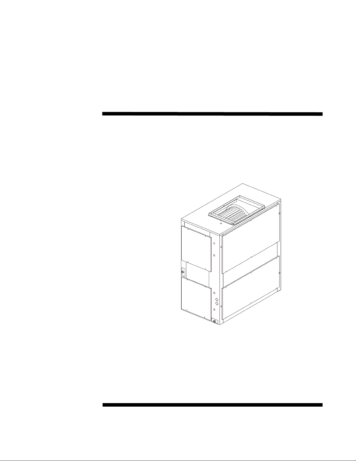
Unit Dimensions
Unit Dimensions
Figure 1.
6 TWE-SVX03C-EN
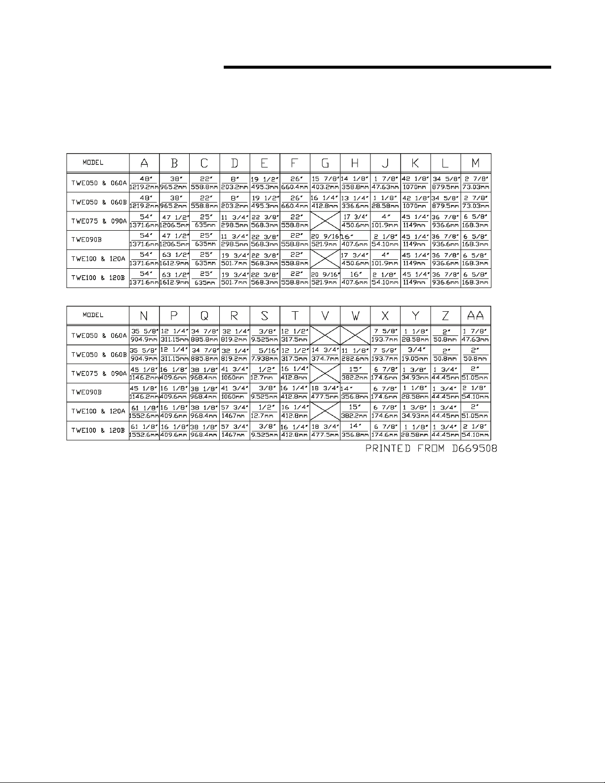
Unit Dimensions
Figure 1. (continued from previous page)
TWE-SVX03C-EN 7
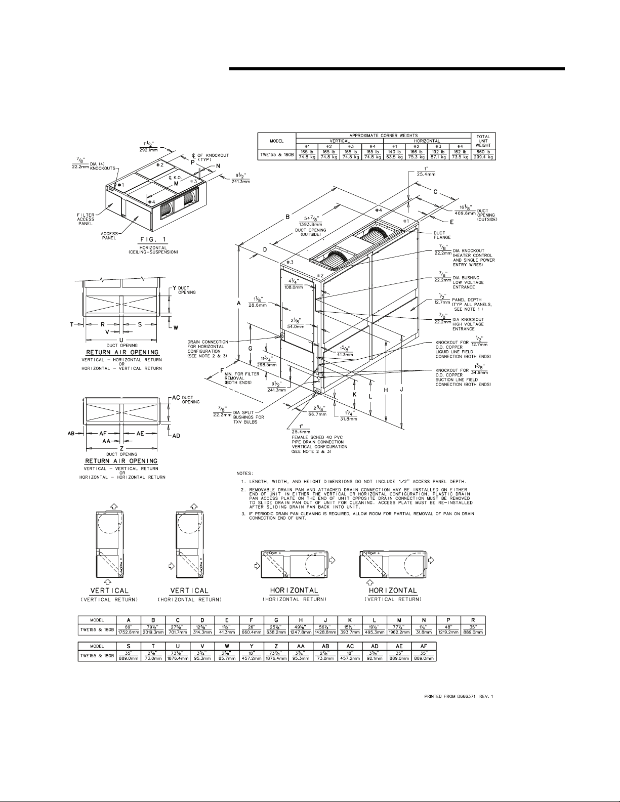
Unit Dimensions
Figure 2.
8 TWE-SVX03C-EN
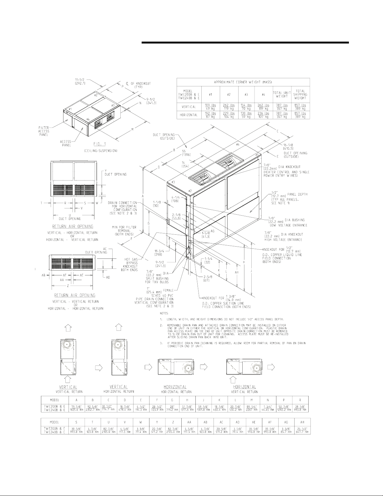
Unit Dimensions
Figure 3.
TWE-SVX03C-EN 9

Installation
Installation Preparations
The final position for the air handler
must be dictated by required service
access to it, weight distribution over
structural supports, and by the
locations of electrical, refrigerant
and condensate drainage
connections. After this is
determined, the following
preparations should be made.
Repositioning Drain Pan
These air handlers come with one
drain pan that can be installed in any
one of four positions; this allows for
vertical or horizontal application and
right or left condensate line
connection. The drain pan can also
be easily removed for periodic
cleaning.
Note: Important! All air handlers
are shipped with the drain
pan installed in the
horizontal position and the
connection on the left side
(as shown in Figure 4). If an
alternate position is required,
the drain pan should be
repositioned before setting
the air handler.
Figure 4.
Process for Drain Pan Relocation
1. Remove the access plate at the
opposite end of the drain
connection. This plate secures
and lifts the back end of the
drain pan for sloping. It must be
removed before the drain pan
can be removed. This is done as
follows:
a. Remove the screw
b. Lift the access plate up
c. Pull the plate out. If the drain
pan is to be moved to the
vertical position also remove
the other two access plates.
2. Remove the screw securing the
drain pan.
a. Lift the pan up
b. Slide the pan out
3. Install the drain pan into the new
position.
a. Slide the drain pan into the
opening
b. Lift the drain pan up
c. Push it in all the way
d. Drop it down over the lip of
the opening, secure with
screw
4. Install the access plate on the
opposite end of the drain pain.
a. Slide the edge of the access
plate under the drain pan
b. Lift the access plate and
drain pan up
c. Push the access plate in
d. Drop the access plate down
over the lip of the opening,
secure with screw. If the
drain pan is being moved to
the vertical position, install
the other access plates over
the horizontal position
opening.
Figure 5.
10 TWE-SVX03C-EN

Installation
Refrigerant Piping Preparation
The air handler is designed so that
refrigerant piping can enter from
either the right or left hand side. It is
shipped with the intent that the
refrigerant lines will enter from the
left hand side. To convert to right
hand entry, unbraze the elbow on the
suction line and rotate 180° and
rebraze.
Note: Important! Access to
refrigerant lines is limited in
all horizontal and some
vertical applications.
Therefore, refrigerant lines
should be stubbed out and
temporarily capped prior to
setting the air handler.
Protect adjacent surfaces
from heat damage when
brazing in and around the air
handler.
Caution
System Component Damage!
These air handlers are shipped with a
dry nitrogen holding charge in the
coil. Cut the process tube or
puncture the cap to bleed off the
nitrogen prior to any brazing.
Temporarily cap off tubes if the
refrigerant line connections are to be
made later.
Installations, Limitations and
Recommendations
The general location of the air
handler is normally selected by the
architect, contractor and/or buyer. For
proper installation the following
items must be considered.
a. Available power supply must
agree with electrical data on
component nameplate.
b. Air Handlers shipped wired
for 208-230 volt applications
can be converted for 460 volt
by rewiring the blower motor
(See Figure 9).
c. If external accessories are
installed on the unit,
additional clearances must be
provided.
d. All duct work should be
properly insulated to prevent
condensation and heat loss.
e. Refrigerant gas piping must
be insulated.
Caution
System Component Damage!
Properly insulate all refrigerant gas
piping to prevent possible water
damage due to condensation and to
prevent capacity loss and possible
compressor damage.
It is recommended that the outline
drawings (pages 3 and 4) be studied
and dimensions properly noted and
checked against the selected
installation site. By noting in advance
which knockouts are to be used,
proper clearance allowances can be
made for installation and possible
future service.
Note: Important! When installing
these units "free standing"
with discharge grills and
isolators, a top support with
isolator should be added to
prevent tipping. Support and
isolator can be attached to a
wall or other appropriate
structure.
Note: Important! If adding external
accessories to the unit,
additional clearances must be
considered for the overall
space needed.
For installation of accessories
available for this air handler, follow
the instructions packed with each
accessory.
Lifting Recommendations
WARNING
Improper Unit Lift!
Test lift unit approximately 24 inches
to verify proper center of gravity lift
point. To avoid dropping of unit,
reposition lifting point if unit is not
level. Failure to properly lift unit
could result in death or serious injury
or possible equipment or propertyonly damage.
Before preparing the unit for lifting,
the center of gravity should be
determined for lifting safety. Because
of the placement of external
components, the unit weight may be
unevenly distributed. Approximate
total unit weight and corner weights
are given in Figure 1- Figure 3.
The crated unit can be moved using a
forklift of suitable capacity. For lifting
the unit into an elevated mounting
position, run lifting straps or slings
under the unit and attach securely to
the lifting device. Use spreader bars
to protect the unit casing from
damage. Test lift the unit to
determine proper balance and
stability.
Caution
Equipment Damage!
Use spreader bars to prevent straps
from damaging the unit. Install the
bars between lifting straps, both
underneath the unit and above the
unit. This will prevent the straps
from crushing the unit cabinet or
damaging the unit finish.
Horizontal Suspension
If the air handler will be suspended,
use a suspension mounting kit to
isolate the unit from the structure.
This is usually accomplished through
the use of spring or rubber isolators,
which are offered as an accessory.
Mounting rods must be field
supplied. Isolator selection is
dependent upon total unit weight
including accessories. Approximate
unit weights are provided in Table 1.
TWE-SVX03C-EN 11

Installation
Caution
Equipment Damage!
Before hanging the unit on
suspension rods, reinforce the
cabinet around the knockouts by
using a large washer inside the
cabinet. Washers should be between
the skin of the air handler and the
nut on the suspension rod.
Align holes (knockouts) in the cabinet
with structural supports and secure
suspension rods to the structure,
then to the air handler cabinet. If
knockout locations do not permit
proper alignment with existing
structure, it may be necessary to field
fabricate cross members on existing
structural beams.
Note: When other than bottom
return is to be used, side
panel removed for return
duct installation must be
secured over the bottom
opening.
Leveling
This air handler has a double sloped
drain pan. In order to assure proper
drainage along the length of the
drain pan, it is important to have the
unit properly leveled. Be sure the air
handler is level or slightly sloped in
the direction of the condensate
connection.
Auxiliary Drain Pan
A field fabricated, auxiliary drain pan
should be installed under the unit for
all horizontal applications and when
air handlers are installed above
ceilings or in other locations where
condensate overflow may cause
damage. This drain pan will eliminate
any excess condensation that may be
due to extreme humidity or an
obstructed drain in the primary drain
pan. Drain lines from this pan must
be installed, but should not be
connected to the primary drain line
from the unit. Isolate the auxiliary
drain pan from both the air handler
and the structure.
WARNING
Fiberglass Wool!
Product contains fiberglass wool.
Disturbing the insulation in this
product during installation,
maintenance or repair will expose
you to airborne particles of glass
wool fibers and ceramic fibers
known to the state of California to
cause cancer through inhalation.
Glass wool fibers may also cause
respiratory, skin or eye irritation.
Precautionary Measures
• Avoid breathing fiberglass dust.
• Use a NIOSH approved dust/mist
respirator.
• Avoid contact with the skin or
eyes. Wear long-sleeved, loosefitting clothing, gloves, and eye
protection.
• Wash clothes separately from
other clothing: rinse washer
thoroughly.
• Operations such as sawing,
blowing, tear-out, and spraying
may generate fiber
concentrations requiring
additional respiratory protection.
Use the appropriate NIOSH
approved respirator in these
situations.
First Aid Measures
Eye Contact - Flush eyes with water
to remove dust. If symptoms persist,
seek medical attention.
Skin Contact - Wash affected areas
gently with soap and warm water
after handling.
Refrigerant Piping
Installation, brazing, leak testing and
evacuation of refrigerant lines are
covered in the installation
instructions packaged with the
outdoor unit. Read the instructions
before beginning installation of
refrigerant lines.
Locate cloth bag(s) attached to the
refrigerant tube of the coil that
contains two (2) brass clamps
(straps) and cork impregnated
insulation material approximately 9"
long by 4" wide. This is for attaching
and insulating the expansion valve
bulb(s) to the suction line(s).
On air handlers that will have
refrigerant lines entering the cabinet
from the left side, remove the split
rubber grommet from the knockout
in the end of the air handler. Uncoil
the cap tub with the bulb attached at
the expansion valve and place the
grommet on the cap tube. With the
grommet around the tube, push the
bulb through the hole and position
the grommet back into its original
position (one bulb and cap tube on
single circuit units and two bulbs and
cap tubes on dual circuit units).
Attach the bulb(s) approximately 45°
off vertical, 10 to 12 inches outside of
the air handler.
On air handlers that will have
refrigerant lines entering the cabinet
from the right side, the bulb(s)
should be attached to the suction
tube(s) inside the cabinet in the same
manner as above, approximately 10"
from the right end of the unit.
After attaching to the suction line(s),
either inside or outside of the
cabinet, wrap the cork impregnated
insulation around the bulb(s) and
suction tube(s). Refrigerant piping
should be insulated.
Note: Important! Ensure that the
refrigerant lines passing
through the cabinet are not
resting on sharp sheet metal
edges.
Condensate Piping
The drain pan condensate
connection is a female slip joint type
for 1" Schedule 40 PVC pipe. Use PVC
cement and tubing as required (field
supplied) to construct a trap. A union
or flexible tubing and clamps may be
installed if the drain pan is to be
removed periodically for cleaning.
12 TWE-SVX03C-EN

Installation
Note: Important! When air handler
.
Figure 6.
is installed in the vertical
position and close proximity
trapping of condensate is
required, use of a subbase
accessory to raise the air
handler for clearance of the
drain trap is recommended.
See Figure 6 for a typical
drain trap assembly
Filters
Air handlers are shipped with
throwaway filters installed. For
replacement filters consult the air
handler service facts for correct size
and number. To replace filters from
the end of the unit, remove lower
access panel (either end) and slide
old filters out and replace with new
ones. To replace from the front of the
unit, remove one "L" shaped angle.
Remove and replace filters and
reinstall "L" shaped angle. See
Figure 7.
.
filter track to increase the width of the
filter opening.
Duct Connections
The supply and return ducts should
be connected to the unit with flame
retardant duct connectors to reduce
vibration transmission. The return
duct should be sized to the same
dimensions as the return inlet of the
unit.
Note: Important! Duct flanges are
provided for attachment of
the duct work. On TWE060,
090, and 120 the flanges are
not installed but are shipped
inside the air handler. While
facing the air handler with the
control box to your left,
remove the upper access
panel. The duct flanges will
be attached to the belly band
of the air handler nearest
you. Remove the screws
securing flanges in place.
Position the four flanges
around the supply opening.
Secure with field supplied
screws, using the predrilled
holes. On TWE180 and 240,
the duct flanges are packaged
on the outside of the cabinet.
Air Flow Settings
Unit is shipped for nominal airflow
with nominal static pressure. Please
refer to fan performance table in
either the product catalog or unit
service facts and select the proper
drive package for each application.
Failure to do so could result in
improper airflow causing coil
frosting or condensate management
problems. Condensate management
problems such as water drip off or
water blow off could be the result of
too great of air face velocity across
the coil.
WARN ING
Hazardous Voltage
w/Capacitors!
Disconnect all electric power,
including remote disconnects and
discharge all motor start/run
capacitors before servicing. Follow
proper lockout/tagout procedures to
ensure the power cannot be
inadvertently energized. Verify with
an appropriate voltmeter that all
capacitors have discharged. Failure
to disconnect power and discharge
capacitors before servicing could
result in death or serious injury.
Note: For additional information
regarding the safe discharge
of capacitors, see
PROD-SVB06A-EN or
PROD-SVB06A-FR.
Figure 7.
To convert from 1" filter to a 2" filter
on units so equipped, remove lower
access panels from both ends of the
air handler. Remove screws and
reposition the "L" shaped angles
from both the top and bottom of the
TWE-SVX03C-EN 13

Installation
WARNING
Hazardous Voltage!
Disconnect all electric power,
including remote disconnects before
servicing. Follow proper lockout/
tagout procedures to ensure the
power can not be inadvertently
energized. Failure to disconnect
power before servicing could result
in death or serious injury.
Electrical Connections
1. All electrical lines, sizing,
protection, and grounding must
be in accordance with the
National Electric Code and local
codes.
2. If conduit is used, isolate
whenever vibration transmission
may cause a noise problem
within the building structure.
3. Ensure all connections are tight
and no wires exposed.
4. All accessories must be installed
and wired according to the
instructions packaged with that
accessory.
For air handler power entry only, or
for dual power entry (power entry for
air handler and power entry for
electric heats), the electrical
connections are made in the fan
control box located in the left side of
the air handler and electric heater
respectively. Wiring entrance is
through holes provided in the end of
the air handler cabinet, see Figure 8.
Breaker or fuse size can be selected
using the nameplates attached to the
unit and electric heater. See pages 13
through 22 for typical
interconnecting wiring diagrams.
Table 1. Recommended t’stat wire size
Wire Size
(Gauge)
22 30 Feet
20 50 Feet
18 75 Feet
16 125 Feet
14 200 Feet
Maximum Wire Length
Physical distance between Unit & T’stat
Figure 8.
Checkout Procedure
Complete the following “installation
checklist” once installation of field
wiring connections is complete. All
operational checks (unit running)
must be made after the outdoor unit
is installed and system
interconnection is complete.
Installation Checklist
Complete this checklist once the unit
is installed to verify that all
recommended procedures have been
accomplished before the system is
started. Operational checks cannot be
performed until the outdoor unit is
installed and system interconnection
is complete.
• Verify that the unit electrical
power is disconnected.
• Inspect all field wiring
connections. All connections
should be clean and tight.
• Inspect unit ground
connection(s). Ground must
comply with all applicable codes.
• Inspect unit suspension
arrangement (if used). Unit
position must be secure. Remove
any tools or debris found in or
near the unit.
• Inspect duct outlets. Outlets
must be open and unrestricted.
• Inspect unit drain lines. Pipe
connections must be tight and
drain line unrestricted.
• Inspect fan assembly to insure all
moving parts move freely.
• If unit is horizontally mounted,
make sure secondary drain pan
has been installed.
• Inspect unit for proper filters,
securely installed. All cabinet
panels must be secure.
• Instruct owner/operator on
proper system operating and
maintenance procedure.
Figure 9.
14 TWE-SVX03C-EN

Thermostat and Control
Connections
1. Observe all notes on the
diagrams.
2. Mount the thermostat in the
desired location.
3. Install color coded low voltage
cables between outdoor unit,
indoor unit and thermostat.
4. Connect low voltage control
wiring to the low voltage
terminal board located on the
side of the fan control box per
the typical interconnecting
wiring diagrams on pages 13
through 22.
TTA090A/TWE090A
TTA120A/TWE120A
Field Wiring:
a. 3 power wires. Line voltage.
b. 3 power wires. Line voltage
for 3 phase; 2 wires for single
phase.
c. Cooling only thermostat: 3
wires, 24 volts.
i. One stage Electric heat:
add 1 additional wire, 24
volts.
ii. Two Stage Electric heat:
add 2 additional wires, 24
volts.
d. 4 wires, 24 volts.
Field Wiring
Figure 10. Field Wiring
TWA090A/TWE090A
TWA120A/TWE120A
Field Wiring:
a. 3 power wires. Line voltage.
b. 3 power wires. Line voltage
for 3 phase; 2 wires for single
phase.
c. Heat pump thermostat: 6
wires, 24 volts.
i. Electric heat: add 2
additional wire, 24 volts.
d. 6 wires, 24 volts.
i. Outdoor thermostat; add
1 additional wire, 24
volts.
ii. Electric heat: add 1
additional wires, 24 volts.
TTA120B/TTE120B
TTA120C/TWE120C
TTA120B/TWE120B
Field Wiring:
a. 3 power wires. Line voltage.
b. 3 power wires. Line voltage
for 3 phase; 2 wires for single
phase.
c. Cooling only thermostat: 4
wires, 24 volts.
i. One Stage Electric heat:
add 1 additional wire, 24
volts.
ii. Two Stage Electric heat:
add 2 additional wires, 24
volts.
d. 5 wires, 24 volts.
TT_060/TWE060A
Field Wiring:
a. 3 power wires. Line voltage.
b. 3 power wires. Line voltage
for 3 phase; 2 wires for single
phase.
c. Cooling only thermostat: 3
wires, 24 volts.
i. One Stage Electric heat:
add 1 additional wire, 24
volts.
ii. Two Stage Electric heat:
add 2 additional wires, 24
volts.
d. 2 wires, 24 volts.
TW_060A/TWE060A
Field Wiring:
a. 3 power wires. Line voltage
for 3 phase; 2 wires for single
phase.
TWE-SVX03C-EN 15

Field Wiring
b. 3 power wires. Line voltage
for 3 phase; 2 wires for single
phase.
c. Heat pump thermostat: 6
wires, 24 volts.
i. Electric heat: add 2
additional wire, 24 volts.
d. 2 wires, 24 volts.
i. Outdoor thermostat; add
1 additional wire, 24 volts.
ii. Electric heat: add 1
additional wire, 24 volts.
(2) TT_060/TTE120B
(2) TT_060/TWE120B
(2) TT_030/TWE060B
Field Wiring:
a. 3 power wires. Line voltage
for 3 phase; 2 wires for single
phase.
b. 3 power wires. Line voltage
for 3 phase; 2 wires for single
phase.
c. Cooling only thermostat: 4
wires, 24 volts.
i. One Stage Electric heat:
add 1 additional wire, 24
volts.
ii. Two Stage Electric heat:
add 2 additional wires, 24
volts.
d. 2 wires, 24 volts to outdoor
section A.
i. 2 wires, 24 volts to
outdoor section B.
(2) TW_030/TWE060B
(2) TW_060/TWE120B
Field Wiring:
a. 3 power wires. Line voltage
for 3 phase; 2 wires for single
phase.
b. 3 power wires. Line voltage
for 3 phase; 2 wires for single
phase.
c. Heat pump thermostat: 7
wires, 24 volts.
i. Electric heat: add 2
additional wire, 24 volts.
d. 5 wires, 24 volts to outdoor
section A.
i. 2 wires, 24 volts to
outdoor section B.
ii. 2 wires, 24 volts between
outdoor sections A and B.
iii. Outdoor thermostat; add
1 additional wire, 24 volts.
iv. Electric heat: add 1
additional wires, 24 volts.
16 TWE-SVX03C-EN

Field Wiring
Figure 11. TTA090A, 120A/TWE090A, 120A; TTA075A, 100A/TWE075A, 100A
Figure 12. TTA120B/TWE120B; TTA120C/TWE120A; TTA100B/TWE100B; TTA100C/TWE100A
TWE-SVX03C-EN 17

Field Wiring
Figure 13. TWA090A, 120A/TWE090A, 120A; TWA075A, 100A/TWE075A, 100A
Figure 14. TTA120B/TWE120B; TTA120C/TWE120A; TTA100B/TWE100B; TTA100C/TWE100A
18 TWE-SVX03C-EN

Field Wiring
Figure 15. TTA090A, 120A/TWE090A, 120A; TTA075A, 100A/TWE075A, 100A
Figure 16. TW_060/TWE060; TW_050/TWE050
TWE-SVX03C-EN 19

Field Wiring
Figure 17. TW_060/TWE060; TW_050/TWE050
Figure 18. TW_060/TWE060; TW_050/TWE050
20 TWE-SVX03C-EN

Field Wiring
Figure 19. TW_030/TWE060B; TW___/TWE090B; TW_060/TWE120B; TW_050/TWE100B
Figure 20. TW_030/TWE060B; TW___/TWE090B; TW_060/TWE120B; TW_050/TWE100B
TWE-SVX03C-EN 21

Figure 21. Field Wiring Outdoor/Indoor
Note: Wiring shown with dashed
lines is to be furnished and
installed by the customer. All
customer-supplied wiring
must be copper only and
must conform to NEC and
local electrical codes. Codes
may require line of sight
between the disconnect
switch and the unit.
Note: When electric heater
accessory is used, single
point power entry or dual
point power entry is field
optional. Single point power
entry option is through the
electric heater only.
Field Wiring
TTA150B/TWE150B
TTA180B/TWE180B
TTA240B/TWE240B
TTA180C/TWE180B
Field Wiring:
a. 3 power wires. Line voltage.
b. 3 power wires. Line voltage
for 3 phase; 2 wires for single
phase.
c. Cooling only thermostat: 4
wires, 24 volts.
i. One Stage Electric heat:
add 1 additional wire, 24
volts.
ii. Two Stage Electric heat:
add 2 additional wires, 24
volts.
d. 5 wires, 24 volts.
TWA180B/TWE180B
TWA240B/TWE240B
Field Wiring:
a. 3 power wires. Line voltage.
b. 3 power wires. Line voltage
for 3 phase; 2 wires for single
phase.
c. Heat pump thermostat: 7
wires, 24 volts.
i. Electric heat: add 2
additional wire, 24 volts.
d. 7 wires, 24 volts.
i. Outdoor thermostat; add
1 additional wire, 24 volts.
ii. Electric heat: add 4
additional wires, 24 volts.
TTA090A/TWE180B
TTA120A/TWE240B
Field Wiring:
a. 3 power wires. Line voltage.
b. 3 power wires. Line voltage
for 3 phase; 2 wires for single
phase.
c. Cooling only thermostat: 4
wires, 24 volts.
i. One Stage Electric heat:
add 1 additional wire, 24
volts.
ii. Two Stage Electric heat:
add 2 additional wires, 24
volts.
d. 6 wires, 24 volts.
(2) TWA090A/TWE180B
(2) TWA120A/TWE240B
Field Wiring:
a. 3 power wires. Line voltage.
b. 3 power wires. Line voltage.
c. Heat pump thermostat: 7
wires, 24 volts.
i. Electric heat: add 2
additional wire, 24 volts.
d. 9 wires, 24 volts.
i. Outdoor thermostat; add
3 additional wire, 24 volts.
ii. Electric heat: add 2
additional wires, 24 volts.
22 TWE-SVX03C-EN

Field Wiring
Figure 22. TTA150B, 180B, 240B/TWE180B, 240B; TTA125B, 155B, 200B/TWE155B, 200B; TTA155C/TWE155B;
TTA180C/TWE180B
Figure 23. TTA150B, 180B, 240B/TWE 180B, 240B; TTA125B, 155B, 200B/TWE155B, 200B; TTA155C/TWE155B;
TTA180C/TWE180B
TWE-SVX03C-EN 23

Field Wiring
Figure 24. TWA180B, 240B/TWE 180B, 240B; TWA155B, 200B/TWE 155B, 200B
Figure 25. TWA 090A, 120A/TWE 180B, 240B; TWA075A, 100A/TWE 155B, 200B
24 TWE-SVX03C-EN

Field Wiring
Figure 26. TTA090A, 120A/TWE 180B, 240B; TTA075A, 100A/TWE155B, 240B
Figure 27. TTA090A, 120A/TWE 180B, 240B; TTA075A, 100A/TWE155B, 200B
TWE-SVX03C-EN 25

Field Wiring
Figure 28. TW_030A/TWE060B; TW___/TWE090B; TW_060/TWE120B; TW_050/TWE100B
26 TWE-SVX03C-EN

Warranty
TTA, TTN, TTP, TTR, TTB, TTX, TTY and TTZ (parts only)
This warranty is extended by
American Standard to the original
purchaser and to any succeeding
owner of the real property to which
the Air Conditioner is originally
affixed, and applies to products
purchased and retained for use
within the U.S.A. and Canada. There
is no warranty against corrosion,
erosion or deterioration.
If any part of your Air Conditioner
fails because of a manufacturing
defect within one year from the date
of original purchase, Warrantor will
furnish without charge the required
replacement part.
In addition, if the sealed motorcompressor(s) fail(s) because of a
manufacturing defect within the
second through fifth year from the
date of original purchase, Warrantor
will furnish without charge a
replacement compressor(s).
Warrantor’s obligations and
liabilities under this warranty are
limited to furnishing F.O.B. Warrantor
factory or warehouse replacement
parts for Warrantor’s products
covered under this warranty.
Warrantor shall not be obligated to
pay for the cost of lost refrigerant.
No liability shall attach to Warrantor
until products have been paid for
and then liability shall be limited
solely to the purchase price of the
equipment under warranty shown to
be defective.
THE WARRANTY AND LIABILITY
SET FORTH HEREIN ARE IN LIEU
OF ALL OTHER WARRANTIES
AND LIABILITIES, WHETHER IN
CONTRACT OR IN NEGLIGENCE,
EXPRESS OR IMPLIED, IN LAW
OR IN FACT, INCLUDING
IMPLIED WARRANTIES OF
MERCHANTABILITY AND
FITNESS FOR PARTICULAR USE,
AND IN NO EVENT SHALL
WARRANTOR BE LIABLE FOR
ANY INCIDENTAL OR
CONSEQUENTIAL DAMAGES.
Some states do not allow limitations
on how long an implied warranty
lasts or do not allow the exclusion or
limitation of incidental or
consequential damages, so the
above limitation or exclusion may
not apply to you. This warranty gives
you specific legal rights, and you
may also have other rights which
vary from state to state.
American Standard Inc.
2701 Wilma Rudolph Blvd.
Clarksville, TN 37040-1008
Attention: Manager, Product Service
TW-338-0597
* This warranty is for commercial
usage of said equipment and not
applicable when the equipment is
used for a residential application.
Commercial use is any application
where the end purchaser uses the
product for other than personal,
family or household purposes.
Commercial Equipment Rated 20 Tons and Larger and Related Accessories (Parts Only)
PRODUCTS COVERED — This
warranty is extended by American
Standard Inc., and applies only to
commercial equipment rated 20 tons
and larger and related accessories
purchased and retained for use
within the U.S.A. and Canada.
Warrantor warrants for a period of 12
months from initial start-up or 18
months from date of shipment,
whichever is less, that the products
covered by this warranty (1) are free
from defects in material and
manufacture, and (2) have the
capacities and ratings set forth in
catalogs and bulletins; provided, that
no warranty is made against
corrosion, erosion or deterioration.
Warrantor’s obligations and
liabilities under this warranty are
limited to furnishing, F.O.B. factory
replacement parts (or equipment at
the option of Warrantor) for all
Warrantor’s products not conforming
to this warranty.
Warrantor shall not be obligated to
pay for the cost of lost refrigerant.
No liability whatever shall attach to
Warrantor until said products have
been paid for and then said liability
shall be limited to the purchase price
of the equipment shown to be
defective.
The Warranty and Liability set forth
herein are in lieu of all other
warranties and liabilities, whether in
contract or in negligence, express or
implied, in law or in fact, including
implied warranties of
merchantability and fitness for
particular use, and in no event shall
warrantor be liable for any incidental
or consequential damages.
Some states do not allow limitations
on how long an implied warranty
lasts or do not allow the exclusion or
limitation of incidental or
consequential damages, so the
above limitation or exclusion may
not apply to you. This warranty gives
you specific legal rights, and you
may also have other rights which
vary from state to state.
American Standard Inc.—Warrantor
2701 Wilma Rudolph Blvd.
Clarksville, TN 37040
GW-598-4799
TWE-SVX03C-EN 27

Literature Order Number TWE-SVX03C-EN
Date October 2006
Supersedes TWE-SVX03C-0906
Stocking Location WebbMason
The manufacturer has a policy of continuous product and product data improvement and reserves
the right to change design and specifications without notice.
 Loading...