

Page 1
Installation
Instructions
SERIN
BATH AND SHOWER TRIM KIT
Thank you for selecting American-Standard...the benchmark
of fine quality for over 100 years.
To ensure that your installation proceeds smoothly--please
read these instructions carefully before you begin.
™
T064.50X
To ensure that your installation proceeds smoothly-please read these
instructions carefully before you begin.
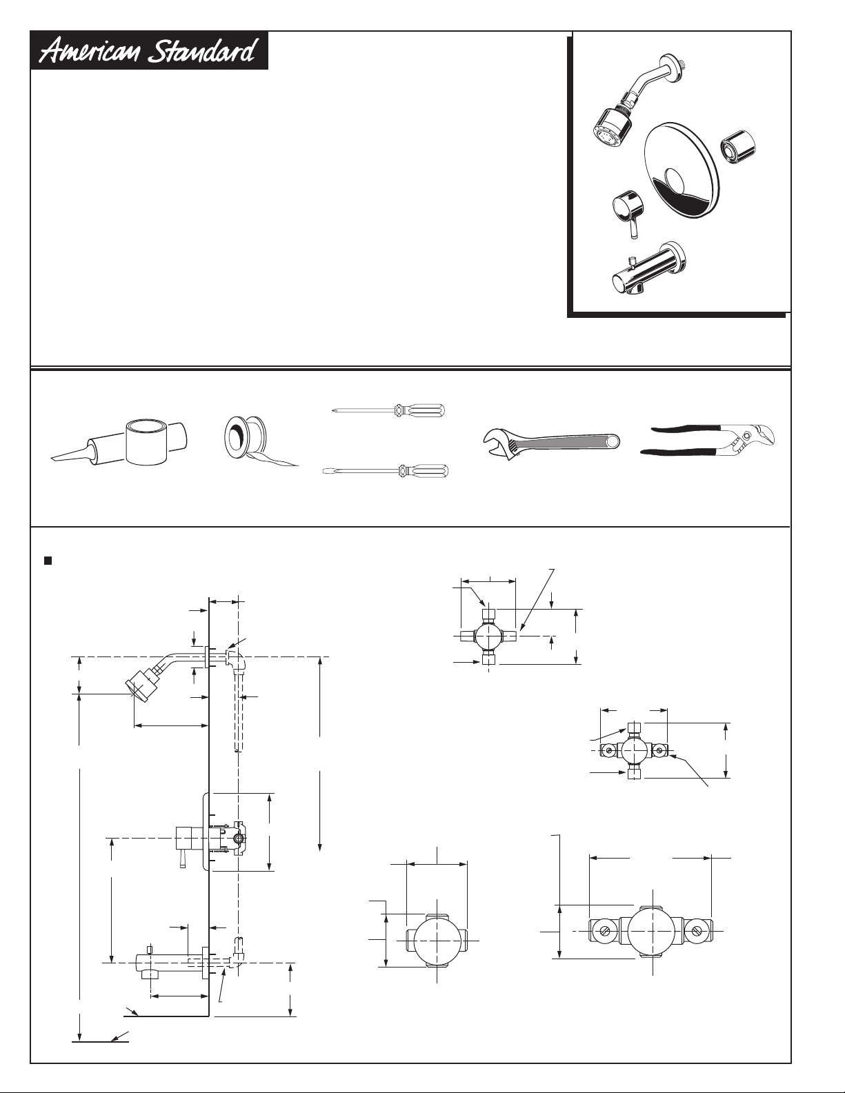
Recommened Tools
Phillips Screwdriver
Plumbers' Putty or Caulking
ROUGHING-IN DIMENSIONS
To assure proper positioning in relation to wall,
note roughing-in dimensions.
FINISHED WALL
5-5/8" REF.
2-3/8"
8-1/8" REF.
74" FOR HEAD
CLEARANCE
18" OPTIONAL
Teflon Tape
1-5/8" TO 3-1/4"
1/2" NPT
1-5/8"
to
3-1/4"
OPTIONAL TO FINISHED
BETWEEN 65'' AND 80''
7-1/4"
FLOOR USUALLY
Flat Blade Screwdriver
SHR. 1/2" NOM.
COPPER SWEAT
SWEAT
INLETS
TUB 1/2" NOM.
COPPER SWEAT
INLETS 1/2" NPT
3-3/8"
INLETS
4-1/16"
Adjustable Wrench
INLETS
1/2" NOM.
COPPER
SWEAT
2"
4-1/16"
SHR. 1/2" NOM.
COPPER SWEAT
TUB 1/2" NOM.
COPPER SWEAT
OUTLETS
1/2" NPT
Certified to comply with ANSI A112.18.1
M968837 Rev.1.5
Channel Locks
SWEAT
INLETS (STOPS)
5-7/8"
4-1/16"
INLETS
1/2" NOM.
COPPER
SWEAT
5-7/8"
INLETS
1/2" NPT
TOP OF TUB RIM
1 -3/4"
4-7/8" REF.
BOTTOM OF TUB
1/2" COPPER
3-3/8"
OUTLETS
1/2" NPT
4"
THREADED INLETS
3-3/8"
THREADED INLETS (STOPS)
Page 2
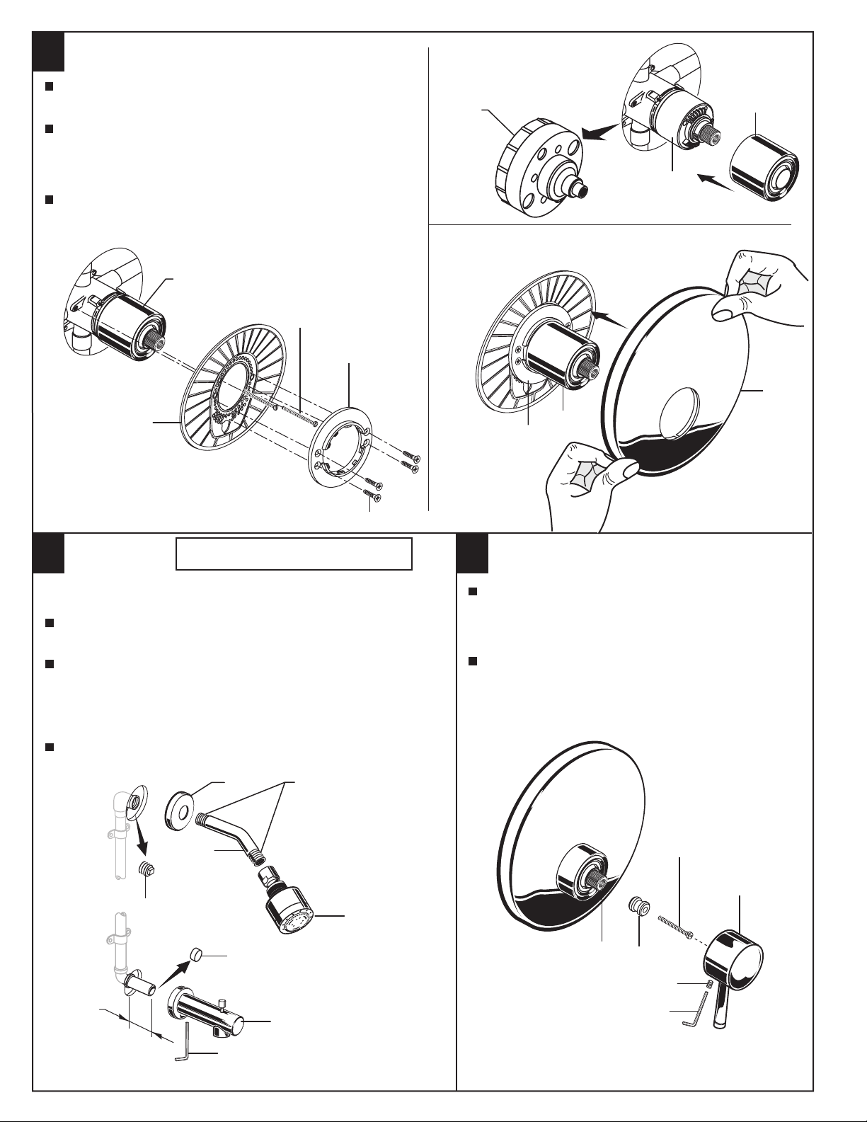
INSTALL VALVE TRIM
1
Figure 1. Remove plaster guard from valve. Push CAP (1)
over VALVE CARTRIDGE (2) until seated against stop.
Figure 2. Push ESCUTCHEON HOLDER (3) onto CAP (1)
and attach to valve body with LONG SCREWS (4). Mount
ESCUTCHEON SUPPORT (5) to ESCUTCHEON HOLDER (3)
with 4 SHORT SCREWS (6).
Figure 3. Install ESCUTCHEON (7) onto CAP (1) and push
flush against finished wall. Escutcheon (7) will snap fit onto
ESCUTCHEON SUPPORT (5).
1
4
5
PLSTER
GUARD
Figure 1.
1
2
7
3
Figure 2.
6
INSTALL TRIM
2
Note: Apply sealant or Teflon Tape to shower arm.
Remove PIPE PLUG and CAP (1, 2) from shower pipe and tub
filler pipe.
Install SHOWER ESCUTCHEON (3) onto SHOWER
ARM (4). Apply sealant or Teflon tape to threads on
both ends of SHOWER ARM (4) and thread longer
leg of SHOWER ARM (4) into shower elbow.
Thread SHOWER HEAD (5) onto SHOWER ARM (4).
Install TUB SPOUT (6). Tighten with HEX WRENCH supplied.
CAUTION: Protect finish on SHOWER
HEAD and TUB SPOUT when installing.
3
APPLY SEALANT OR
TEFLON TAPE TO THREADS
1
5
Figure 3.
INSTALL HANDLE
3
Hold ADAPTER (1) onto VALVE STEM (2) and install
ADAPTER SCREW (3) through ADAPTER (1) into
VALVE STEM (2).Tighten ADAPTER SCREW (3) to
secure ADAPTER (1) to VALVE STEM (2).
Install HANDLE BASE (4) onto ADAPTER (1). Insert
SET SCREW (5) into HANDLE BASE (4). Align
HANDLE BASE (4) and tighten with HEX WRENCH
(6) supplied.
1-3/4"
4
3
4
1
2
5
2
1
5
6
HEX WRENCH
6
M968837 Rev.1.5
Page 3

ADJUST HOT LIMIT STOP
4
By restricting HANDLE rotation and limiting the amount of hot
water allowed to mix with the cold, the HOT LIMIT SAFETY
STOP (1) reduces risk of accidental scalding. To set the maximum
2
7
9
5
1
3
1
1
3
0
1
4
5
1
3
5
1
hot water temperature of your faucet, all you need to do
is adjust the setting on the HOT LIMIT SAFETY STOP (1).
Turn CARTRIDGE STEM (2) to the OFF position (coldest setting) before
3
making adjustment to HOT LIMIT STOP (1). Use aflat blade screwdriver to pry
free the HOT LIMIT SAFETY STOP (1). Pull forward and rotate counterclockwise
one number to limit hot water temperature. Use ARROW (3) on CARTRIDGE (4)
and NUMBERS (5) on HOT LIMIT STOP (1) for indication.
TO GAIN ACCESS TO VALVE FOR SERVICING
5
Remove HANDLE (see step 3 and reverse).
Remove ESCUTCHEON and CARRIDGE CAP (see step 1 and reverse).
Shut off water supply by either closing off main water supply, or closing off
the hot and cold CHECK STOPS on valve.
1
5
1
3
1
1
9
7
5
3
1
4
COLDER
(Larger Numbers)
0 1 3 5 7 9 11 13 15
2
HOTTER
(Smaller Numbers)
0 1 3 5 7 9 11 13 15
1
5
1
3
1
1
9
7
5
3
1
5
1
VALVE LEAKS WHEN SHUT OFF
Remove CARTRIDGE (1) by removing CARTRIDGE SCREWS (2). Remove three SCREWS (3) from FIXATION RING (4) and
pull out PRESSURE BALANCING (5) unit.
Clean SEALS (9) on base of CARTRIDGE (1). Check base of PRESSURE BALANCING UNIT (5) and clean O-RINGS (6). Remove
CAPS (7) and check O-RINGS on inside of CAPS (7). Clean inside sealing surfaces of VALVE BODY (8).
Re-assemble PRESSURE BALANCING UNIT (5) and CARTRIDGE (1). Tighten all screws.
Turn on water supply and see above for installing TRIM and HANDLE.
UNABLE TO MAINTAIN CONSTANT TEMPERATURE
Remove PRESSURE BALANCE UNIT (5).
Remove CAPS (7) and clean valve thoroughly.
Examine balancing unit and check condition of O-ring on end of piston. Piston should move back and forth. Order Repair
Part M952100-0070A if balancing unit is defective.
Replace CAPS (7) and install PRESSURE BALANCE UNIT (5). Make sure inlets line up with two holes in bottom of casting.
Top flange should butt-up against top of casting.
BACK TO BACK INSTALLATION
Remove PRESSURE BALANCE UNIT (5). Rotate PRESSURE BALANCE UNIT (5) 180˚ so that the inlets face up and the
large outlet port faces down.
Push PRESSURE BALANCE UNIT (5) in casting make sure inlets line up with holes in bottom of casting. Top flange should
butt up against top of casting.
Reassemble FIXATION RING (4) and CARTRIDGE (1).
4
1
LARGE OUTLET
ROTATE 180˚
8
7
6
CARE INSTRUCTIONS:
6
5
3
9
2
5
INLETS
BACK TO BACK INSTALLATION
DO: SIMPLY RINSE THE PRODUCT CLEAN WITH CLEAR WATER. DRY WITH A SOFT COTTON FLANNEL CLOTH.
DO NOT: DO NOT CLEAN THE PRODUCT WITH SOAPS, ACID, POLISH, ABRASIVES, HARSH CLEANERS, OR A
CLOTH WITH A COARSE SURFACE.
M968837 Rev.1.5
 Loading...