


American Standard 2476.216, 2476.516, 2480.516, 2480.216, 2484.516 User Manual
...
INSTALLATION INSTRUCTIONS
CARE AND MAINTENANCE
FloWise™ DUAL FLUSH 2-PIECE TOILET
Model 2479.216 / 2479.516 |
/ 2476.216 |
/ 2476.516 |
/ 2779.516 |
|
Model 2480.216 / 2480.516 |
/ 2484.216 |
/ 2484.516 |
/ 2778.516 / |
Certified by |
IAPMO R&T
2566.216 Right Height™
Thank you for selecting American Standard - the benchmark of fine quality for over 100 years. To ensure this product is installed properly, please read these instructions carefully before you begin. (Certain installations may require professional help.) Also be sure your installation conforms to local codes.
!CAUTION: PRODUCT IS FRAGILE. TO AVOID BREAKAGE AND POSSIBLE INJURY HANDLE WITH CARE!
NOTE: Pictures may not exactly define contour of china and components.
RECOMMENDED TOOLS AND MATERIALS
Putty Knife |
Regular Screwdriver |
Adjustable Wrench |
Sealant |
Tape Measure |
Hacksaw |
Wax Ring/Gasket |
Flexible Supply Tube |
Closet Bolts |
Carpenters Level |
1REMOVE OLD TOILET
a.Close toilet supply valve and flush tank completely. Towel or sponge remaining water from tank and bowl.
b.Disconnect and remove supply line.
NOTE: If replacing valve, first shut off main water supply!
c.Remove old mounting hardware, remove toilet and plug floor waste opening to prevent escaping sewer gases.
d.Remove closet bolts from flange and clean away old wax, putty, etc. from base area.
|
|
NOTE: Mounting surface must be clean and level before new toilet is installed! |
|
|
|
||||||||||
2 ROUGHING-IN DIMENSIONS: |
|
|
|
|
|
Models: 2480.216 / 2480.516 / 2484.216 / 2484.516 / |
|||||||||
|
|
|
|
|
2778.516 / 2566.216 Right Height™ |
|
|||||||||
|
|
|
|
Models: 2479.216 / 2479.516 / |
|
|
|
|
|||||||
|
|
|
|
2476.216 / 2476.516 / 2779.516 |
|
|
|
FINISHED WALL |
|
|
|
||||
|
|
FINISHED WALL |
|
|
|
|
794mm |
|
|
|
|||||
|
|
|
|
794mm |
|
|
|
|
|
|
|
(31-1/4) |
|
|
|
|
|
|
|
|
|
|
|
|
|
41mm ± 6mm |
|
|
432mm |
||
|
|
41mm ± 6mm |
|
(31-1/4) |
|
|
|
|
|
|
(1-5/8±1/4) |
|
|
||
|
|
|
|
|
|
432mm |
|
|
|
197mm |
|
|
|
(17) |
|
|
|
(1-5/8±1/4) |
|
|
|
|
|
|
|
|
|
|
PUSH |
||
|
|
197mm |
|
|
|
|
(17) |
|
|
|
(7-3/4) |
|
|
|
BUTTON |
|
|
|
|
|
|
PUSH |
|
|
|
|
|
|
|||
|
|
(7-3/4) |
|
|
|
|
BUTTON |
|
|
|
|
|
|
|
|
|
|
|
|
|
|
|
|
|
|
|
|
470mm |
|
|
C/L |
|
|
|
|
470mm |
|
|
|
|
|
|
|
(18-1/2) |
|
|
|
|
|
|
|
|
|
C/L |
|
|
|
|
|
|
|
||
|
|
|
|
(18-1/2) |
|
|
|
|
|
|
|
|
|
|
|
|
|
|
|
|
|
|
|
|
|
|
|
|
|
|
|
|
|
|
|
|
|
|
|
|
|
|
|
C/L OF SEAT POST HOLES |
|
|
|
|
|
|
|
C/L OF SEAT POST HOLES |
|
|
|
|
|
|
140mm (5-1/2 CENTRES) |
|
|
||
|
|
|
|
140mm (5-1/2 CENTRES) |
|
|
|
|
|
|
|
|
|
|
|
|
|
|
|
|
|
|
|
|
|
|
|
|
|
*SUPPLY |
|
|
|
|
|
|
|
SUPPLY |
|
|
|
|
|
|
|
AS |
829m |
|
|
|
|
|
|
|
|
|
|
|
|
|
REQ'D |
||
|
|
|
|
|
|
AS |
|
765mm |
111mm |
|
|
|
|
(32-5/8)m |
|
111mm |
3/8)-(4 |
|
|
|
375mm |
REQ'D |
|
3/8)-(4 |
|
|
(17-5/8) |
|
|
||
|
|
|
|
(30-1/8) |
|
|
|
|
|||||||
|
|
|
|
|
|
|
|
|
|
|
|
|
|
||
|
|
|
|
|
|
|
|
|
|
|
|
|
|
|
|
|
|
|
|
|
|
|
|
|
|
|
|
|
448mm |
|
|
|
|
|
|
|
(14-3/4) |
|
|
|
|
|
|
|
|
203mm |
370mm |
|
|
|
|
|
|
203mm |
371mm |
|
|
|
|
|
|
(8) |
(14-5/8) |
|
|
|
|
|
|
(8) |
(14-5/8) |
|
|
|
|
|
|
|
|
|
|
121mm |
|
|
|
|
|
|
|
|
121mm |
410mm |
|
114mm |
|
|
|
|
397mm |
|
114mm |
|
|
|
|
(4-3/4) |
FINISHED |
(4-1/2) |
|
||
|
|
|
|
|
|
|
|
(16-1/8) |
|
||||||
|
|
(4-3/4) |
|
(15-5/8) |
FINISHED |
(4-1/2) |
|
|
|
305mm |
FLOOR |
|
265mm |
||
|
|
|
251mm |
|
|
|
|
||||||||
|
|
305mm |
|
|
FLOOR |
|
|
|
C/L OF OUTLET |
|
|
||||
|
|
C/L OF OUTLET |
|
|
|
|
(12) |
|
|
(10-3/8) |
|||||
|
|
(12) |
|
|
(9-7/8) |
|
|
|
|
|
|
||||
|
|
|
|
|
|
|
|
|
|
|
|
||||
3 |
CLOSET |
|
4 |
|
|
|
|
5 |
|
|
|
|
|||
|
|
|
|
|
|
|
|
|
|
|
|
|
|||
|
|
FLANGE |
|
|
|
|
|
|
|
|
|
|
|
||
|
|
|
|
A |
|
SEALANT |
WAX RING |
|
|
|
|
BOLT |
|||
|
|
|
|
|
|
|
|
|
|
|
|
CAP |
|||
|
|
|
|
|
|
|
|
|
|
|
|
|
|
|
NUT |
|
|
CLOSET |
|
|
|
|
|
|
|
|
|
|
|
|
TAPERED |
|
|
BOLTS |
|
|
|
|
|
|
|
|
|
|
|
|
WASHER |
|
INSTALL CLOSET BOLTS |
|
|
|
|
|
|
|
|
|
CLOSET |
|
|||
|
Install closet bolts in flange channel, |
|
|
|
|
|
|
|
|
BOLT |
|
||||
|
turn 90°, and slide into place 6" |
|
|
|
|
|
|
|
|
|
|
|
|||
|
(152mm) apart and parallel to wall. |
|
|
|
|
|
|
|
FLANGE |
|
|
||||
|
TEMPORARILY set toilet in place. |
|
|
|
|
|
|
|
|
|
|||||
|
|
|
|
|
|
|
|
|
|
|
|||||
|
Place tapered washer and nuts onto |
INSTALL WAX SEAL |
|
|
|
|
|
|
|
|
|||||
|
the bolts as shown in Step 5. Mark bolt |
|
|
|
POSITION TOILET ON FLANGE |
|
|
||||||||
|
Invert toilet on floor (cushion to |
|
|
|
|
||||||||||
|
length needed for bolt cap clearance. |
|
|
|
|
||||||||||
|
Remove toilet. Precut the bolts to |
prevent damage), and install wax |
a. Unplug floor waste opening and install toilet on closet flange |
||||||||||||
|
length by twisting the nut onto the bolt |
ring evenly around waste flange |
|
|
so bolts project through mounting holes. |
|
|||||||||
|
past the cut mark, then cutting the bolt |
(horn), with tapered end of ring |
|
|
b. Loosely install retainer washers and nuts. Side of washers |
||||||||||
|
to the desired length with a hacksaw. |
facing toilet. Apply a thin bead of |
|
marked "THIS SIDE UP" must face up! |
|
||||||||||
|
Unscrew the nut to repair the threads. |
sealant around toilet base. |
|
|
|
|
|
|
|
||||||
|
Re-install bolts in flange. |
|
|
|
|
|
|
|
|
|
|
|
|||
P r o d u c t n a m e s l i s t e d h e r e i n a r e t r a d e m a r k s o f A S A m e r i c a I n c . |
7301144-100 Rev. F |
© A S A m e r i c a I n c . 2 0 0 8 |
S A V E F O R F U T U R E U S E
6
BOLT CAP
CLOSET FLANGE
CLOSET BOLT
WASHER NUT
INSTALL TOILET
a.Position toilet squarely to wall and, with a rocking motion, press bowl down fully on wax ring and flange. Alternately tighten nuts until toilet is firmly seated on floor.
!CAUTION:
DO NOT OVERTIGHTEN NUTS
b.Install caps on washers.
c.Smooth off the bead of sealant around base. Remove excess sealant.
7Tank Installation Kit Includes:
2 bolts, 2 rubber washers, 4 metal washers, 4 metal nuts, 2 plastic nuts, 1 large rubber gasket.
RUBBER
 WASHER
RUBBER
TANK MTG.  GASKET
BOLTS
WASHER
NUT
WASHER
NUT
INSTALL TANK
a.Discard plastic nuts.
b.Install tank mounting bolts and rubber washers from inside tank, through mounting holes and secure with one metal washer and one nut per bolt.
c.Install large rubber gasket over threaded outlet on bottom of tank and lower tank onto bowl so that tapered end of gasket fits evenly into bowl water inlet opening.
d.With tank parallel to wall, secure tank to bowl using remaining two metal washers and nuts. Alternately tighten nuts until tank is snugged down evenly against bowl surface.
*USE NUT DRIVER OR DEEP SOCKET RACHET.
!CAUTION:
DO NOT OVERTIGHTEN NUTS MORE THAN REQUIRED FOR A SNUG FIT!
8 INSTALL TOILET SEAT Install toilet seat in accordance with manufacturer's directions.
9a |
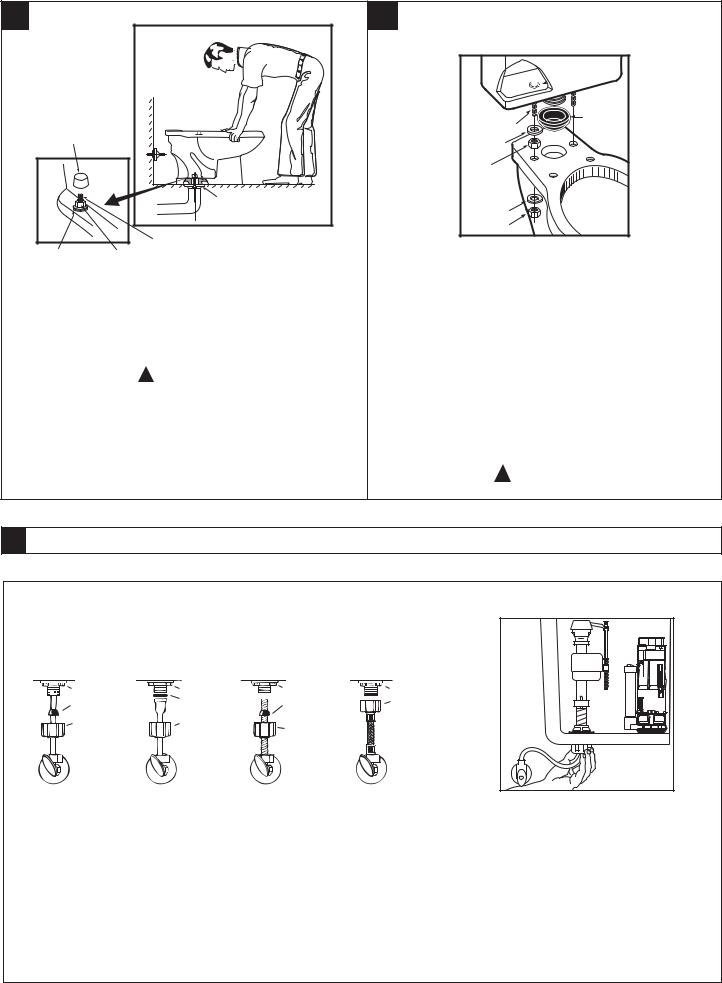
Before continuing, determine the type of water supply connection you have from |
|
9b |
|||||||
|
|
the chart below and use the appropriate assembly parts required to properly |
|
|
||||||
|
|
reconnect the water supply. DO NOT use plumber's putty to seal these fittings. |
|
|
||||||
|
METAL / COPPER |
METAL FLANGED |
METAL SPIRAL |
VINYL / BRAIDED |
|
|
||||
|
FLARED TUBING |
|
TUBING |
TUBING |
CONNECTOR |
|
|
|||
|
|
LOCK NUT |
|
LOCK NUT |
|
LOCK NUT |
LOCK NUT |
|
|
|
|
|
CONE |
|
EXISTING |
|
EXISTING |
COUPLING |
|
|
|
|
|
|
WASHER |
|
|
|
||||
|
|
WASHER |
|
|
CONE |
NUT |
|
|
||
|
|
COUPLING |
|
EXISTING |
|
WASHER |
|
|
|
|
|
|
|
|
|
|
|
|
|||
|
|
NUT |
|
COUPLING |
|
COUPLING |
|
|
|
|
|
|
|
|
NUT |
|
NUT |
|
|
|
|
|
|
WATER |
|
WATER |
|
WATER |
WATER |
|
|
|
|
|
SHUT-OFF |
|
SHUT-OFF |
|
SHUT-OFF |
SHUT-OFF |
|
|
|
These parts must be used as |
|
Use existing |
Use existing spiral |
Captive cone |
|
|
||||
illustrated to insure water-tight |
coupling nut |
cone washer. |
washers already |
|
|
|||||
connection. Use of existing |
|
and washer. |
Fluidmaster cone |
included. No |
|
|
||||
coupling nut may result in |
|
|
|
washer may not |
additional washers |
|
|
|||
water leakage. Water supply |
|
|
|
seal completely on |
needed. |
|
|
|||
tube or pipe must extend at |
|
|
|
spiral type supply |
|
|
|
|||
least 1/2" inside threaded |
|
|
|
line. |
|
|
|
|||
shank of valve (does not |
|
|
|
|
|
|
|
|
||
apply to flanged tubing). |
|
|
|
|
|
|
|
|
||
|
|
|
|
|
|
|
||||
|
CAUTION: DO NOT USE |
|
|
CAUTION: Overtightening of |
|
|
||||
|
CONE WASHER WITH |
|
|
LOCK NUT or COUPLING NUT |
|
|
||||
|
|
|
could result in breakage and |
|
|
|||||
|
PLASTIC SUPPLY LINE. |
|
|
potential flooding. |
|
|
||||
|
|
|
|
|
|
|
|
|
|
|
With correct washers in place (see Step 9a), tighten COUPLING NUT 1/4 turn beyond hand tight.
DO NOT OVERTIGHTEN.
7301144-100 Rev. F
- 2 -
 Loading...