

American Metal Ware AT-2W, AT-2WE, AT-AP, AT-APE, AT-3W Installation Manual
...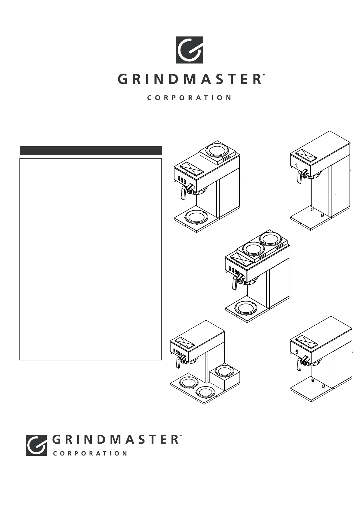
Model AT-2W/AT-2WE
Model AT-AP/AT-APE
Model AT-3WR/AT-3WRE
Model AT-TC/AT-TCE
AUTO-SERIES BREWERS
Installation, Operation, and Service Manual
TABLE OF
C
ONTENTS
Warning Labels ........................................................3
Water Connection ...................................................4
Installation Instructions ........................................4
Coffee Preparation Procedures ...........................5
Brew Volume Adjustment ....................................5
Brew Basket Rail Adjustment ...............................5
Spare Parts List ..........................................................6
Water Tank Assembly Drawing ...........................7
AT-2W/AT-2WE Drawing ........................................8
AT-AP/AT-APE Drawing..........................................9
AT-3WR/AT-3WRE Drawing .................................10
AT-TC/AT-TCE Drawing ..........................................11
Troubleshooting Guide .......................................13
Component Replacement Instructions ..........14
© Grindmaster Corporation, 2007
PRINTED IN THAILAND
0307 Form # BW-340-02
Part # 73254
Prior authorization must be obtained from
Grindmaster Corporation™ for all warranty claims.
Grindmaster Corporation™
4003 Collins Lane
Louisville, Kentucky 40245 USA
(502) 425-4776
(800) 695-4500
(USA and Canada only)
(800) 568-5715 (Technical Service only)
FAX: (502) 425-4664
www.grindmaster.com
AT-3W/AT-3WE Drawing ......................................12
Model AT-3W/AT-3WE

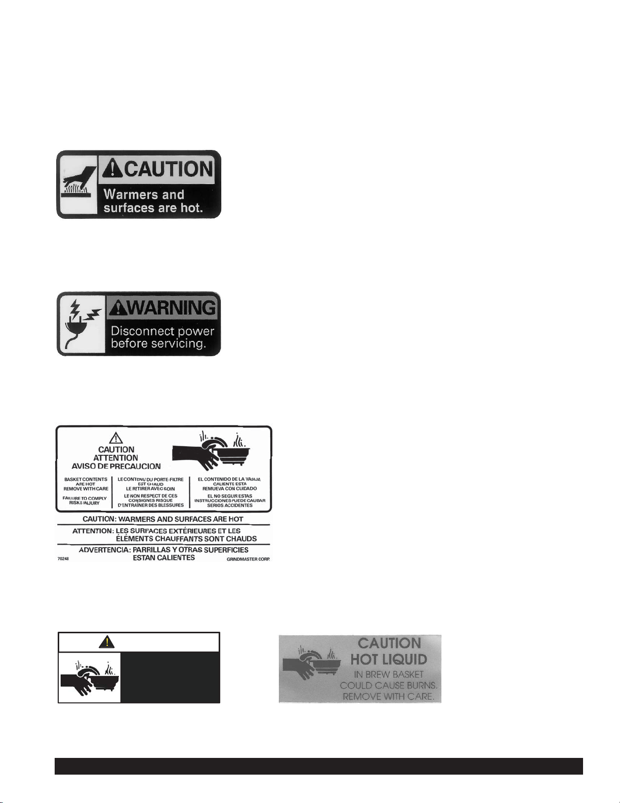
WARNING LABELS
The following warning labels were on your dispenser when it was shipped from the factory. They should remain on your
dispenser in good, readable condition at all times. If one of your labels is missing or damaged, order a replacement label
immediately.
Part # 71509 (for warmer models only)
Located near warmer plates
Part # 71582
Located on rear and top access panels
Part # 70248
Located on front, behind server
Part # 71949 or 71149
Located on brew basket
CAUTION
Hot liquid in brew
basket could cause
burns.
Remove with care.
Part #71949
Auto Series Brewer Manual Page 3
Part #71149

INSTALLATION INSTRUCTIONS
1) Place the decanter under brew basket, raise top evaporation cover and pour three decanters of water through the
top pour-in opening. Water should come through the brew basket as the third decanter of water drains out of the
pour-in basin.
2) Brewer is shipped with thermostat turned on, (full clockwise position). Plug brewer into a dedicated, grounded
120V/15A circuit (230V/15A circuit for E models).
3) Allow 10-15 minutes for water in tank to heat to brewing temperature. (Hot water may drip from brew basket on
initial thermal expansion of water in the tank). This will not occur thereafter.
4) After water has reached brewing temperature (thermostat will click off, heating noise will stop and green ready light
will be on) pour 1 decanter (60 oz./1.8L) of water through pour-in opening. Machine is now ready to use.
5) Pour 1 decanter of water through pour-in opening to check for proper temperature setting with an accurate
thermometer. Take the temperature of this water at a point below the brew basket opening at the start of the brew
cycle and when the decanter is half full. Recommended temperature of the water is approximately 195°F (91°C) .
6) In higher altitude locations (5,000 feet/1,500m above sea level) the thermostat may have to be adjusted lower to
prevent boiling.
WARNING - Read and follow installation instructions before plugging or wiring in machine to electrical circuit.
Warranty will be void if unit is connected to any voltage other than that listed on the name plate.
FILL BREWER TANK WITH WATER BEFORE CONNECTION TO POWER SUPPLY
WATER CONNECTION
The following is required for water hook-up:
1) A quick disconnect water connection or enough coiled tubing so the machine can be moved for cleaning
underneath. ( required for NSF approved water hook-up )
2) A 1/4" male flare adapter is provided to be attached by the installer to the back of the machine for hook-up to
water supply.
3) Installation to a water filter system is required to prevent lime and scale build up in the machine.
4) Water pipe connections and fixtures directly connected to potable water supply shall be sized, installed, and
maintained in accordance with Federal, State, and Local codes. ( required for NSF approved water hook-up )
5) Equipment is to be installed with adequate backflow protection to comply with applicable Federal, State,
and local codes. ( required for NSF approved water hook-up )
Minimum water pressure to the machine: 30 psi (2.0 bar)
Maximum water pressure to the machine: 80 psi (5.6 bar)
Page 4 Auto Series Brewer Manual

COFFEE PREPARATION PROCEDURES (Pour-Over Mode)
1) Place filter into brew basket.
2) Put the proper amount of coffee into the filter.
3) Slide the brew basket into holder.
4) Place empty decanter on warmer located directly under the brew basket and turn corresponding warmer switch ON.
NOTE: For airpots, open airpot lid, remove pump stem from airpot and place airpot opening directly under center hole
in brew basket.
5) Pour decanter of fresh water through pour-in opening at top of brewer.
6) Hot water will be delivered through the sprayhead. This distributes the hot water evenly over the coffee bed within
the brew basket. The coffee will drain from brew basket into the container below.
7) TURN OFF WARMER WHEN NOT IN USE. (Red light indicates warmer is ON.) Not for airpot brewers.
8) Before brewing next pot, remove brew basket from brew rails and dump filter into waste basket.
Auto Series Brewer Manual Page 5
COFFEE PREPARATION PROCEDURES (Auto Mode)
1) Place filter into brew basket.
2) Put the proper amount of coffee into the filter.
3) Slide the brew basket into holder.
4) Place empty decanter on warmer located directly under the brew basket and turn corresponding warmer switch ON.
NOTE: For airpots, open airpot lid, remove pump stem from airpot and place airpot opening directly under center hole
in brew basket.
5) Press Brew switch once then release.
6) Valve will turn on approximately 1 minute and fill pour-in basin.
7) Hot water will be delivered through the sprayhead. This distributes the hot water evenly over the coffee bed within
the brew basket. The coffee will drain from brew basket into the container below.
8) TURN OFF WARMER WHEN NOT IN USE. (Red light indicates warmer is ON.) Not for airpot brewers.
9) Before brewing next pot, remove brew basket from brew rails and dump filter into waste basket.
10) Do not press Brew switch more than once during brew cycle.
BREW BASKET RAIL ADJUSTMENT
1) Disconnect power to brewer.
2) Remove lid and pour-in basin.
3) Loosen nuts for brew rails.
4) Fit basket in place.
5) Tighten nuts and check basket fit.
BREW VOLUME ADJUSTMENT
1) Disconnect power to brewer.
2) Remove plug on upper left side of chassis.
3) With a flat head screwdriver, turn dial clockwise slightly to increase volume and counter-clockwise to decrease
volume.
4)
Reconnect power and run a brew cycle to check volume.
5) Repeat steps 1-3 if necessary.
Reference timer setting:
Water Pressure (psi) Timer setting(sec) Volume (oz)
35 64 64
40 63 64
50 62 64
Page 6 Auto Series Brewer Manual
SPARE PARTS LIST
Not shown:
61530 Power Cord, 120V
6145
3 Power Cord, 230V
Item No. Part No. Description Item No. Part No. Description
1 73035 Water Tank 38 73242 Hole Plug
2A 73252 Clamp Hose, Nylon .468" ID 39 71093 Pipe Adapter
2B 73283 Clamp Hose, Nylon .531" ID 40 73179 Timer Relay, 120V
3 71155 Tubing, 5/16"ID x 1/2"OD Silicone 73251 Timer Relay, 230V
4 73318 Heat Exchanger Inside Tank 3/8" ID 41 73114 Bracket, Panel Spray HD
5 70818 Element, Heating 1400W 120V 42 73003 Top Cover SS, AT-AP, AT-3WR
7082
0 Element, Heating 2500W 240V 43 71607 Panel, Pour-Over Lid
7322
2 Element, Heating 1780W 120V 44 71529 Wire Hinge, Pour-Over Lid
6 73037-1 Inlet Tube Assembly 45 73008 Nut Slotted Hex SS (size M20x1.5)
7 73186A Cover, Tank W/Bracket, Thermostat 46 73010 Pan, Receiving
8 61143 Nut, Pipe Jam 1/8" NPT 47 73175 Assy, Water Line to Faucet
9A 73317 Fitting Brass 1/4"MFL x 3/8"NPT 48 73188A Top Body Assemply AT-AP, AT-TC
9B 73177 Fitting Brass 1/4"MFL x 1/4"NPT 49 73191 Panel, Back AT-AP, AT-APE
10 73033 Elbow Brass, 1/8" NPT 3/8" Barb 50 73291 Valve Inlet 120V, 50/60Hz
11 61243 Grommet, Dump Valve 73298 Valve Inlet 230V, 50/60Hz
12 73178 Fitting, 1/4"MFL x 3/8" Barb 51 73021 Bracket, Tank Base AT-AP, AT-APE
13 73234 Tube, Inner Braided Silicone 52 73192 Panel Center SS. AT-AP, AT-APE
14 60550 Clamp Hose, Stainless 53 73190 Panel, Back AT-TC, AT-2W, AT-3WR
15 73036 Thermostat Regulating 54 73213 Base Tank
16 61150 Valve, Ambient Flow Control Assy 55 73185 Panel Center SS. AT-TC, AT-2W, AT-3WR
17 62237 T-Stat, Hi-Limit, 120V Models 56 73029 Base Cover Panel, AT-2W, AT-3W
10052
3 T-Stat, 1/2" Manual Reset 230V Models 57A 73321-1 Decal, Main Front AT-2W
18 62238 Bracket, Hi-Limit 120V Models 57B 73321 Decal, Main Front W/Switch Power AT-2W
10052
4 Bracket, Hi-Limit Manual Reset 230V Models 58 73031 Panel, Warmer Top AT-2W
19 73095 Bracket, Water Tank 59 73001 Bracket, Warmer
20 73057 Gasket, Tank O-Ring 60 73002 Plate, Warmer
21 73096 Thermostat Clip Lock 61 13029 Heater, Warmer 120V, 100W
22 61232 Plug 3/8" Barbed A535-028 Heater, Warmer 220V, 100W
23 73028 Leg, Support 62 73004 Top Cover SS, AT-2W
24 73026 Base Welded 63 73218A Top Body Assemply AT-2W
25 73024 Base Cover Panel, AT-AP, AT-AC 64 73079 Base Welded AT-3WR
26 73027 Airpot Stopper 65 73080 Base Cover Panel, AT-3WR
27
A 73183 Rail Brew, RH. Assembly 66 73078 Panel, Warmer 3RD, AT-3WR
B 73182 Rail Brew, LH. Assembly 67A
27
28 71952 Brew Basket 67B
29 73249 Pressure Faucet 68 73184A Top Body Assemply AT-3WR
30 63495 Ready Light, Green 120V 69
61125 Ready Light, Green 240V
31 70445 Brew Switch
A 73058 Switch Warmer Lighted 230V
32
7305
9 Switch Warmer Lighted 120V
B 73194 Switch Power - Optional
32
A 73320-1 Decal, Main Front AT-AP, AT-TC
33
33B 73320 Decal, Main Front W/Switch Power AT-AP, AT-TC
34 06491 Deflector, Spray HD
35 06490 Nozzle, Spray HD
36 07220 Nut, Lock Palnut Spray HD
37 70341 Elbow, Silicone 90 deg 79 73288
73319-1
73319
61237
70 73292 Elbow, Barbed 3/8" Hose ID x 3/8" NPT
71 73294 Orifice, Flow Control, 0.5 GPM
72 73293 Barb, 3/8" Hose ID x 3/8" NPT
73 73312 Grommet Pipe Connect Silicone
74 73315 Bracket, Pipe Connect
75 73313 Pipe connect 1/4” OD
76 73314 Tubing Silicone 0.2” ID x 0.5” OD
77
A 73297-1 Decal, Main Front AT-3W
77
B 73297 Decal, Main Front AT-3W, W/Switch Power
78 73287 Top Cover SS, AT-3W
Decal, Main Front AT-3WR
Decal, Main Front W/Switch Power AT-3WR
Fitting Assembly 1/4MFL x 3/4Hs Brass
Panel, 2 Warmers
 Loading...