


 Loading...
EXCELLENCE IN MAGNETICS AND CRYOGENICS
MODEL 185/186 LIQUID LEVEL
INSTRUMENT
INSTALLATION, OPERATION, AND
MAINTENANCE INSTRUCTIONS
American Magnetics, Inc.
PO Box 2509, 112 Flint Road, Oak Ridge, TN 37831-2509, Tel: 865 482-1056, Fax: 865 482-5472
Rev. 3, September 2011

Declaration of Conformity
Application of Council Directives: |
Low Voltage Directive 72/23/EEC |
|
EMC Directive 89/336/EEC |
Manufacturer’s Name: |
American Magnetics, Inc. |
Manufacturer’s Address: |
112 Flint Road, |
|
P.O. Box 2509 |
|
Oak Ridge, TN 37831-2509 |
|
U.S.A. |
Type of Equipment: |
Liquid Level Instruments |
Model Numbers: |
Model 185 and 186 |
Standards to which Conformity is Declared:
Safety: |
EN 61010-1 |
(1993) w/A1, A2 |
|
|
EMC: |
EN55011 (1991) Group 1, Class A |
|
||
|
EN50082-1 (1997) |
/ EN61000-4-2 (1995) |
8kV AD, 4kV CD |
|
|
EN50082-1 (1997) |
/ EN61000-4-3 (1996) |
3V/m |
|
|
EN50082-1 (1997) |
/ EN61000-4-4 (1995) |
1kV Power Supply |
|
|
|
|
|
0.5kV I/O cables |
|
EN50082-1 |
(1997) |
/ EN61000-4-5 (1995) |
2kV CM, 1kV DM |
|
EN50082-1 |
(1997) |
/ EN61000-4-6 (1996) |
3V |
|
EN58082-1 |
(1997) |
/ EN61000-4-11 (1994) |
Voltage dips 30% - 10ms |
|
|
|
|
Voltage dips 60% - 100ms |
|
|
|
|
Short interruption >95% - 5s |
I, the undersigned, hereby declare that the equipment specified above complies with the requirements of the aforementioned Directives and Standards and carries the "CE" mark accordingly.
Gregory J. Laughon |
September 12, 2002 |
Quality Assurance Manager |
|
American Magnetics, Inc. |
|
Oak Ridge, TN, U.S.A. |
|

Table of Contents
1 |
Introduction .............................................................................. |
|
1 |
|
|
1.1 |
Model 185/186 Features............................................................ |
1 |
|
|
1.2 |
Model 185 |
Front Panel.............................................................. |
3 |
|
1.3 |
Model 185 |
Rear Panel ............................................................... |
4 |
|
1.4 |
Model 186 Front Panel Layout ................................................ |
5 |
|
|
1.5 |
Model 186 |
Rear Panel Layout .................................................. |
6 |
|
1.6 |
Model 185/186 Specifications @ 25 °C ...................................... |
8 |
|
2 |
Installation .............................................................................. |
11 |
|
|
2.1 |
Unpacking the Instrument ..................................................... |
11 |
|
2.2 |
Rack Mounting the Instrument.............................................. |
12 |
|
2.3 |
Installing the Sensor in the Cryo-vessel ................................ |
12 |
|
2.4 |
Connecting the Oscillator Cable to the AMI Sensor ............. |
13 |
|
2.5 |
Connecting the Instrument to the Oscillator......................... |
13 |
|
2.6 |
Installing an Optional Solenoid-operated Fill Valve............. |
14 |
|
2.7 |
Connecting the Instrument to Power..................................... |
15 |
3 |
Calibration |
.............................................................................. |
17 |
|
|
3.1 |
Relationship between Calibration and Sensor Length ......... |
17 |
|
|
3.2 |
Variations in the Dielectric with Changing Density ............. |
17 |
|
|
3.3 |
Calibration Methods for Model 185/186 Instruments ........... |
19 |
|
|
|
3.3.1 |
Open dewar calibration ............................................... |
21 |
|
|
3.3.2 |
Closed dewar calibration............................................. |
21 |
|
|
3.3.3 |
Approximate calibration ............................................. |
25 |
4 |
Operation ................................................................................ |
29 |
|
|
4.1 |
Normal Operations.................................................................. |
29 |
|
|
4.1.1 Energize the instrument ............................................. |
29 |
|
|
4.1.2 Configure the active length setting ............................ |
29 |
|
|
4.1.3 Configure the HI SETPOINT and the |
|
|
|
LO SETPOINT............................................................. |
30 |
|
|
4.1.4 Configure the A SETPOINT and the B SETPOINT.. |
31 |
|
|
4.1.5 Select the operational mode of the controller |
|
|
|
output receptacle ......................................................... |
32 |
|
|
4.1.6 Configure the INTERVAL setting (fill timer) |
|
|
|
if desired....................................................................... |
32 |
|
|
4.1.7 Select the appropriate units display option ............... |
33 |
|
|
4.1.8 Connect the optional analog output signal ................ |
33 |
|
4.2 |
Sensor Contamination ............................................................ |
34 |
Rev. 3 |
v |

Table of Contents
5 |
Remote Interface Reference .................................................. |
35 |
||
|
5.1 |
Serial Communication/Data Logger Option ........................... |
35 |
|
|
|
5.1.1 Serial port connector and cabling................................ |
35 |
|
|
|
5.1.2 |
Command/return termination characters................... |
35 |
|
|
5.1.3 Serial Communication DIP Switch Settings............... |
36 |
|
|
|
5.1.4 Serial Command Set Reference ................................... |
38 |
|
|
5.2 |
IEEE-488 Communication Option .......................................... |
42 |
|
|
|
5.2.1 |
Command/return termination characters................... |
42 |
|
|
5.2.2 Communicating with the Model 185/186 .................... |
42 |
|
|
|
5.2.3 IEEE-488 Communication DIP Switch Settings ........ |
44 |
|
|
|
5.2.4 IEEE-488 Command Set Reference ............................ |
46 |
|
|
|
5.2.5 Serial poll status byte .................................................. |
49 |
|
|
5.3 |
Error Codes............................................................................... |
50 |
|
6 |
Virtual Instrument Operation ................................................. |
51 |
|
|
6.1 |
RS-232 Virtual Instrument ..................................................... |
51 |
|
|
6.1.1 Launching and initializing the RS-232 VI .................. |
52 |
|
|
6.1.2 Interacting with the running VI.................................. |
54 |
|
6.2 |
IEEE-488 Virtual Instrument ................................................. |
55 |
|
|
6.2.1 Launching and initializing the GPIB VI..................... |
56 |
|
|
6.2.2 Interacting with the running VI.................................. |
57 |
|
|
6.2.3 Running multiple GPIB devices .................................. |
58 |
7 |
Service Guide .......................................................................... |
61 |
|
|
7.1 |
Troubleshooting Procedures .................................................... |
61 |
|
|
7.1.1 No level reading............................................................ |
62 |
|
|
7.1.2 Erratic or erroneous level reading............................... |
63 |
|
|
7.1.3 Controller output does not energize ............................ |
64 |
|
|
7.1.4 Unit not responding to communications ..................... |
64 |
|
7.2 |
Custom Instrument Configurations........................................ |
65 |
|
|
7.2.1 Modifying the line voltage requirements .................... |
65 |
|
7.3 |
Additional Technical Support.................................................. |
66 |
|
7.4 |
Return Authorization............................................................... |
66 |
Appendix.................................................................................. |
67 |
|
A.1 |
4-20 mA current loop option .................................................... |
67 |
A.2 |
Auxiliary connector J2 pinout ................................................. |
68 |
A.3 |
RS-232 cable DB-25 to DB-9 translation ................................ |
69 |
A.4 |
RS-422 Cable Wiring................................................................ |
69 |
A.5 |
Dielectric constants for common liquids ................................. |
70 |
Index......................................................................................... |
71 |
|
vi |
Rev. 3 |

Foreword
Purpose and Scope
This manual contains the operation and maintenance instructions for the American Magnetics, Inc. Model 185/186 Liquid Level Instrument. The manual outlines the instructions for instrument use in various system designs. Since it is impossible to cover all possible system/sensor designs, the most common configuration is discussed and the user is encouraged to contact an authorized AMI Technical Support Representative for information regarding specific configurations not explicitly covered in this manual.
Contents of This Manual
Introduction introduces the reader to the functions and characteristics of the instrument. It provides the primary illustrations of the front and rear panel layouts as well as documenting the performance specifications.
Installation describes how the instrument is unpacked and installed in conjunction with ancillary equipment in a typical cryogenic system.
Operation describes how the instrument is used to measure and control liquid level. All instrument controls are documented.
Remote Interface Reference documents all remote commands and queries available through the serial and IEEE-488 interfaces. A quickreference summary of commands is provided as well as a detailed description of each.
Service provides guidelines to assist Qualified Service Personnel in troubleshooting possible system and instrument malfunctions. Information for contacting AMI Technical Support personnel is also provided.
The Appendix documents the rear panel connectors.
Rev. 3 |
vii |

Foreword
Applicable Hardware
Applicable Hardware
The Model 185/186 has been designed to operate with an AMI LiquidLevel Sensor. Operation with other equipment is not recommended and may void the warranty.
General Precautions
Cryogen Safety
Personnel handling cryogenic liquids should be thoroughly instructed and trained as to the nature of the liquids. Training is essential to minimize accidental spilling. Due to the coldness of these materials, a cryogen spilled on many objects or surfaces may damage the surface or cause the object to shatter, often in an explosive manner.
Inert gases released into a confined or inadequately ventilated space can displace sufficient oxygen to make the local atmosphere incapable of sustaining life. Cryogenic liquefied gases are potentially extreme suffocation hazards since a small amount of liquid will vaporize and yield a very large volume of oxygen-displacing gas. Always ensure the location where the cryogen is used is well ventilated. Breathing air with insufficient oxygen content may cause unconsciousness without warning. If a space is suspect, purge the space completely with air and test before entry. If this is not possible, wear a forced-air respirator and enter only with a co-worker standing by wearing a forced-air respirator.
Cryogenic liquids, due to their extremely low temperatures, will burn the skin in a similar manner as would hot liquids. Never permit cryogenic liquids to come into contact with the skin or allow liquid nitrogen to soak clothing. Serious burns may result from careless handling. Never touch uninsulated pipes or vessels containing cryogenic liquids. Flesh will stick to extremely cold materials. Even nonmetallic materials are dangerous to touch at low temperatures. The vapors expelled during the venting process are sufficiently cold to burn flesh or freeze optic tissues. Insulated gloves should be used to prevent frost-bite when operating valves on cryogenic tanks. Be suspicious of valves on cryogenic systems; the extremes of temperature they undergo causes seals to fail frequently.
In the event a person is burned by a cryogen or material cooled to cryogenic temperatures, the following first aid treatment should be given pending the arrival and treatment of a physician or other medical care worker:
1.If any cryogenic liquid contacts the skin or eyes, immediately flush the affected area gently with tepid water (102°F − 105°F, 38.9°C − 40.5°C) and then apply cold compresses.
viii |
Rev. 3 |

Foreword
Safety Summary
2.Do not apply heat. Loosen any clothing that may restrict circulation. Apply a sterile protective dressing to the affected area.
3.If the skin is blistered or there is any chance that the eyes have been affected, get the patient immediately to a physician for treatment.
Containers of cryogenic liquids are self pressurizing (as the liquid boils off, vapor pressure increases). Hoses or lines used to transfer these liquids should never be sealed at both ends (i.e. by closing valves at both ends).
When pouring cryogenic liquids from one container to another, the receiving container should be cooled gradually to prevent damage by thermal shock. The liquid should be poured slowly to avoid spattering due to rapid boil off. The receiving vessel should be vented during the transfer.
Introduction of a substance at or near room temperature into a cryogenic liquid should be done with great caution. There may be a violent gas boil off and a considerable amount of splashing as a result of this rapid boiling. There is also a chance that the material may crack or catastrophically fail due to forces caused by large differences in thermal contraction of different regions of the material. Personnel engaged in this type of activity should be instructed concerning this hazard and should always wear a full face shield and protective clothing. If severe spraying or splashing could occur, safety glasses or chemical goggles along with body length protective aprons will provide additional protection.
The properties of many materials at extremely low temperatures may be quite different from the properties that these same materials exhibit at room temperatures. Exercise extreme care when handling materials cooled to cryogenic temperatures until the properties of these materials under these conditions are known.
Metals to be used for use in cryogenic equipment application must posses sufficient physical properties at these low temperatures. Since ordinary carbon steels, and to somewhat a lesser extent, alloy steels, lose much of their ductility at low temperatures, they are considered unsatisfactory and sometimes unsafe for these applications. The austinetic Ni-Cr alloys exhibit good ductility at these low temperatures and the most widely used is 18-8 stainless steel. Copper, Monel®, brass and aluminum are also considered satisfactory materials for cryogenic service.
Safety Summary
Cryogenic storage systems are complex systems with the potential to seriously injure personnel or equipment if not operated according to procedures. Proper use of safety mechanisms (pressure relief valves,
Rev. 3 |
ix |
Foreword
Safety/Manual Legend
rupture disks, etc.) included in the cryostat and top plate assembly are necessary.
Recommended Safety Equipment
‡First Aid kit
‡Fire extinguisher rated for class C fires
‡Leather gloves
‡Face shield
‡Signs to indicate that there are potentially dangerous cryogens in use in the area.
Safety/Manual Legend
Instruction manual symbol: the product is marked with this symbol when it is necessary for you to refer to the instruction manual in order to protect against damage to the product or personal injury.
Hazardous voltage symbol.
Alternating Current (Refer to IEC 417, No. 5032).
Off (Supply) (Refer to IEC 417, No. 5008).
On (Supply) (Refer to IEC 417, No. 5007).
Warning
The Warning sign denotes a hazard. It calls attention to a procedure or practice, which if not correctly adhered to, could result in personal injury. Do not proceed beyond a Warning sign until the indicated conditions are fully understood and met.
Caution
The Caution sign denotes a hazard. It calls attention to an operating procedure or practice, which if not adhered to, could cause damage or destruction of a part or all of the product. Do not proceed beyond a Caution sign until the indicated conditions are fully understood and met.
0RGHO This marking in the left margin of the manual designates a feature, procedure, or specification that is unique to the Model 186.
x |
Rev. 3 |
1 Introduction
1.1 Model 185/186 Features
The American Magnetics, Inc. (AMI) Model 186 Liquid Level Controller system is an advanced, microprocessor-based solution designed to provide accurate and reliable level monitoring and control of virtually any cryogenic liquid.
1.1.1Capacitance-based level sensing
The system consists of a Model 185/186 Liquid Level Instrument, sensor, connecting cables, and an optional solenoid-operated fill valve. The instrument sensing element is typically a 3/8 inch (9.5 mm) OD cylindrical capacitor constructed of stainless steel which allows a cryogenic fluid to become the dielectric between the concentric plates. The instrument measures the sensor capacitance which is directly related to the percentage of the sensor immersed in the cryogenic liquid. The sensors are normally constructed in overall lengths of up to 20 feet (6.1 m). The maximum active length is typically 7 inches less than the overall sensor length.
1.1.2HI/LO level alarms
The Model 185/186 provides two alarm setpoints for both HI and LO level indication. The HI and LO level alarms activate front panel LEDs, an audible alarm, and two independent sets of relay contacts accessible from the rear panel. All setpoints are continuously adjustable from the front panel.
1.1.3Level control
0RGHO The Model 186 adds two additional setpoints which are used to specify a control band for the liquid level. The Model 186 automatically energizes and de-energizes a rear panel controller output receptacle which is typically used to operate a solenoid valve. The controller output receptacle state can be manually overridden from the front panel. A fill timeout feature is also provided which can be used to terminate the fill function after a user-specified period of time.
1.1.4Convenient display
The instrument is equipped with a 4-digit LED display which provides liquid level indication in inches, centimeters, or percent as selected by a front panel switch. A front panel switch allows the user to adjust the instrument length quickly and easily for a specific active sensor length. The sensor active length can be entered in either inches or centimeters.
Rev. 3 |
1 |

Introduction
The length adjustment only affects the scaling of the level display and does not change the actual calibration of the instrument.
1.1.5Microprocessor-based electronics
Microprocessor-based electronics provide 0.1% readout accuracy. Nonvolatile memory maintains instrument calibration without battery backup. Watchdog timer circuitry and low line voltage (brownout) detector prevent microprocessor lockup and provide fail-safe operation.
1.1.6Remote computer monitoring or controlled operation
The Model 185/186 can be optionally equipped with a 0-10 volt recorder output. A 4-20 mA current loop option is available in lieu of the recorder output. Available computer interface options include RS-232/422 Serial Port/Data Logger or IEEE-488.
The Model 185/186 may be optionally configured for a maximum of one analog output option and one computer interface option.
2 |
Rev. 3 |
Introduction
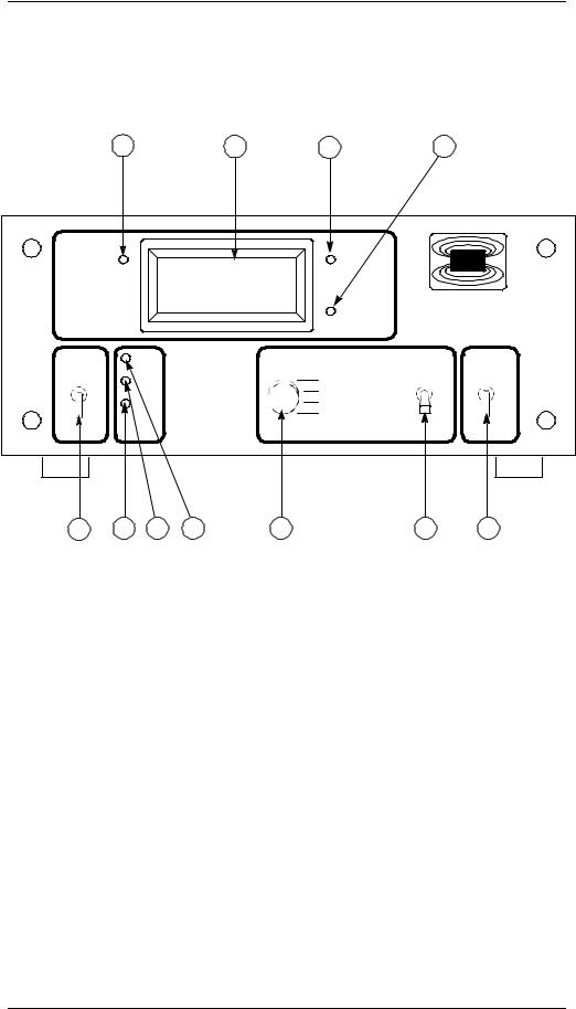
Model 185 Front Panel Layout
1 |
2 |
3 |
4 |
$&7,9,7< |
100.0 |
+, /(9(/ |
|
/2 /(9(/ |
$0,
0RGHO
/LTXLG /HYHO ,QVWUXPHQW
O |
0$; |
5$,6( |
,1&+ |
|
a |
+, 6(732,17 |
|
|
|
/2 6(732,17 |
|
|
0,1 |
/(1*7+ |
|
|
|
||
|
|
|
|
|
|
6,/(1&( |
|
2 |
&$/ |
/2:(5 |
&0 |
5 |
6 |
7 |
8 |
9 |
10 |
11 |
1 |
Activity LED |
6 |
MIN calibration push-button |
|
|
|
|
2 |
LED display |
7 |
Approximate calibration push-button |
|
|
|
|
3 |
HI level LED |
8 |
MAX calibration push-button |
|
|
|
|
4 |
LO level LED |
9 |
Control mode rotary switch |
|
|
|
|
5 |
Power toggle switch |
10 |
Raise/lower toggle switch |
|
|
|
|
|
|
11 |
Units mode toggle switch |
|
|
|
|
Rev. 3 |
3 |

Introduction
Model 185 Rear Panel Layout
1
ON |
RS-232 |
S11 |
J8 |
|
&20081,&$7,216 |
-
-
$0(5,&$1 0$*1(7,&6 ,1& 2$. 5,'*( 71 8 6 $
 /,1( +] 9$ 0$;
|
|
|
|
|
|
|
|
|
|
9 |
|
|
|
9 |
|||
|
|
|
|
|||||
|
9 |
|
|
|
9 |
|||
|
|
|
|
|||||
|
|
|
|
|
|
|
|
|
|
|
|
|
|
|
|
|
|
|
|
|
|
|
|
|
|
|
2 |
3 |
4 |
1 |
Optional RS-232/422 or IEEE- |
3 |
RG-59/U coaxial connector to |
|
488 communications port |
|
oscillator unit via the extension |
|
(RS-232 shown) |
|
cable |
|
|
|
|
2 |
Auxiliary DB-9 connector |
4 |
Input power connector |
|
(see Appendix for pinout) |
|
|
|
|
|
|
4 |
Rev. 3 |
Introduction
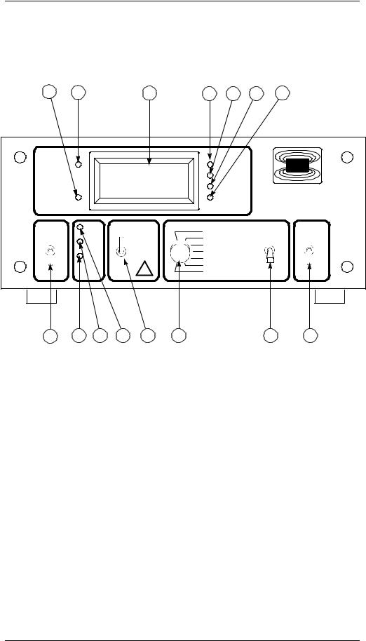
Model 186 Front Panel Layout
1 |
2 |
3 |
4 |
5 |
6 |
7 |
$&7,9,7< |
|
100.0 |
|
+, /(9(/ |
|
$0, |
),// |
|
|
/2 /(9(/ |
0RGHO |
||
|
|
|
|
$ |
|
|
|
|
|
|
% |
|
|
|
|
|
|
|
/LTXLG /HYHO |
|
|
|
|
|
|
&RQWUROOHU |
|
O |
0$; |
$872 |
+, |
6(732,176 |
5$,6( |
,1&+ |
|
|
&/26(' |
|
|
||
|
|
/2 |
} |
|
||
|
a |
|
$ |
|
|
|
|
|
% |
|
|
|
|
|
0,1 |
|
/(1*7+ |
|
|
|
|
|
|
|
|
||
2 |
|
23(1 |
,17(59$/ |
|
|
|
&$/ |
6,/(1&( |
/2:(5 |
&0 |
|||
8 |
9 |
10 |
11 |
12 |
13 |
14 |
15 |
1 |
Fill indication LED |
9 |
MIN calibration push-button |
|
|
|
|
2 |
Activity LED |
10 |
Approximate calibration push-button |
|
|
|
|
3 |
LED display |
11 |
MAX calibration push-button |
|
|
|
|
4 |
HI level LED |
12 |
Fill toggle switch |
|
|
|
|
5 |
A level LED |
13 |
Control mode rotary switch |
|
(control band upper limit) |
|
|
|
|
|
|
6 |
B level LED |
14 |
Raise/lower toggle switch |
|
(control band lower limit) |
|
|
|
|
|
|
7 |
LO level LED |
15 |
Units mode toggle switch |
|
|
|
|
8 |
Power toggle switch |
|
|
|
|
|
|
Rev. 3 |
5 |

Introduction
Model 186 Rear Panel Layout
1
ON |
RS-232 |
|
|
|
|
|
|
$0(5,&$1 0$*1(7,&6 ,1& |
|
|
|
|
2$. 5,'*( 71 8 6 $ |
|
S11 |
J8 |
|
|
|
|
&20081,&$7,216 |
&21752//(5 287387 |
|
|
|
|
/,1( +] $ 0$; |
||
|
|
|
||
|
- |
|
|
|
|
|
|
|
|
- |
|
|
|
|
|
|
/,1( 92/7$*( $ 0$; |
9 |
9 |
|
|
9 |
9 |
|
|
|
|
||
2 |
3 |
4 |
5 |
1 |
Optional RS-232/422 or IEEE- |
4 |
Controller output receptacle |
|
488 communications port |
|
|
|
(RS-232 shown) |
|
|
|
|
|
|
2 |
Auxiliary DB-9 connector |
5 |
Input power connector |
|
(see Appendix for pinout) |
|
|
3RG-59/U coaxial connector to oscillator unit via the extension cable
6 |
Rev. 3 |

Introduction
Instrument/Sensor System Diagram
SOLENOID-OPERATED FLOW VALVE  (OPTIONAL)
EXTENSION CABLE
RG-59/U COAXIAL
CABLE, 6 FT. LENGTH
STANDARD (VARIABLE)
REAR PANEL
ON |
RS-232 |
|
|
|
|
|
|
|
$0(5,&$1 0$*1(7,&6 ,1& |
||
|
|
|
2$. 5,'*( 71 8 6 $ |
||
S11 |
J8 |
|
|
|
|
|
&20081,&$7,216 |
&21752//(5 287387 |
|
|
|
|
|
|
/,1( +] $ 0$; |
||
|
|
|
|
||
|
- |
|
|
|
|
|
|
|
|
|
|
- |
|
|
|
|
|
|
|
/,1( 92/7$*( $ 0$; |
9 |
9 |
|
|
|
9 |
9 |
||
OSCILLATOR
MODEL 186
LIQUID LEVEL
CONTROLLER
OSCILLATOR CABLE RG-59/U COAXIAL CABLE, 6 FT. LENGTH (FIXED)
$&7,9,7< |
+, /(9(/ $0, |
),// |
100.0 /2 /(9(/ 0RGHO |
$
%
/LTXLG /HYHO &RQWUROOHU
|
|
0$; |
$872 |
|
|
5$,6( |
,1&+ |
|
O a |
|
|
+,%$ 32,1766(7 |
|
|
|
|
&/26(' |
/2} |
|
|
|||
|
|
0,1 |
|
|
/(1*7+ |
|
|
|
2 |
|
|
|
,17(59$/ |
|
|
|
&$/ |
23(1 |
6,/(1&( /2:(5 |
&0 |
|||
|
|
|
|||||
|
3/8 NPT NYLON |
|
|
|
|
|
|
|
FEED-THROUGH |
|
|
|
|
|
|
|
(OTHER MOUNTING FRONT PANEL |
|
|
|
|||
TOTAL |
OPTIONS AVAILABLE) |
|
|
|
|
|
|
SENSOR |
|
|
|
|
|
|
|
LENGTH |
|
|
|
|
|
|
|
|
A PROPERLY CONNECTED WARM |
||||||
12-255.9" |
SENSOR CAN READ ~ +2% UNTIL COOL |
||||||
ACTIVE |
SENSOR |
|
|
|
|
|
|
SENSOR LENGTH (SPECIFY)
Model 186 instrument, control valve, and sensor system diagram.
Rev. 3 |
7 |

Introduction
Specifications
1.6 Model 185/186 Specifications @ 25 °C
0RGHO
0RGHO
0RGHO
Level Measurementsa
Resolution: |
0.1%, 0.1 cm, or 0.1 in |
Linearity: |
± 0.1% |
Maximum Length Readout: |
650.0 cm (255.9 in) |
|
|
Operating Parameters
HI and LO Alarms: |
0 % to 100% adjustable |
HI/LO Alarm Relay Contact Ratings: |
10 VA, 30 VAC or 60 VDC, 0.5 A |
|
(normally open, closed on alarm) |
A and B Control Setpoints: |
0 % to 100% adjustable |
Controller Output: |
AC line voltage @ 2A max current |
Fill Timer: |
0.1 to 600.0 minutes |
|
|
0-10 Volt Analog Output
Integral Non-linearity: |
± |
0.012% |
Resolution: |
16 bits |
|
Total Error: |
± |
1.1% for 0-10 V output |
Voltage Drift (0-10 V): |
100 ppm / °C |
|
Maximum Load: |
4 mA (2.5 kΩ @ 10 V output) |
|
|
|
|
4-20 mA Analog Output @ 24 V
Vext Supply Range: |
|
13-32 VDC (see Appendix for diagram) |
Voltage Compliance: |
|
Vext − 3.5 |
Integral Non-linearity: |
|
± 0.012% |
Resolution: |
|
16 bits |
Total Error: |
|
± 0.25% for 4-20 mA output |
Current Drift (4-20 mA): |
|
75 ppm / °C |
PSRR: |
|
10 µ A / V |
|
|
|
Power Requirements |
|
|
Primaryb: |
|
110-120 or 208-240 VAC ± 10% |
|
||
|
|
50 - 60 Hz |
|
|
For Japan or S. Korea: 100 or 200 VAC ± 10% |
Maximum Current: |
|
30 VA for Model 185 |
|
|
2.2 A for Model 186 |
|
|
|
8 |
Rev. 3 |

Introduction
Specifications
Physical
Dimensions (Standard): |
97 mm H x 213 mm W x 282 mm D |
|
(3.8" H x 8.4" W x 11.1" D) |
Weight (Standard): |
1.6 kg (3.6 lbs.) |
Dimensions (Rack Mount): |
89 mm H x 483 mm W x 282 mm D |
|
(3.5" H x 19" W x 11.1" D) |
Weight (Rack Mount): |
2.0 kg (4.3 lbs.) |
|
|
Environmental
Ambient Temperature: |
Operating: 0 °C to 50 °C (32 °F to 122 °F) |
|
Nonoperating: − 20 °C to 60 °C (− 4 °F to 140 °F) |
Relative Humidity: |
0 to 95%; non-condensing |
|
|
a.Under extreme radiated electromagnetic field conditions (3V/m at 450 MHz to 610 MHz), the accuracy may be degraded by an additional ± 0.7%.
b.Units configured for Japan or South Korea cannot be configured for operation at other voltages without an internal transformer change, and vice-versa.
Rev. 3 |
9 |

Introduction
Specifications
10 |
Rev. 3 |
2 Installation
Warning
Before energizing the instrument, the earth ground of the power receptacle must be verified to be at earth potential and able to carry the rated current of the power circuit. Using extension cords should be avoided; however, if one must be used, ensure the ground conductor is intact and capable of carrying the rated current.
In the event that the ground path of the instrument becomes less than sufficient to carry the rated current of the power circuit, the instrument should be disconnected from power, labeled as unsafe, and removed from place of operation.
Do not operate this instrument in the presence of flammable gases. Doing so could result in a life-threatening explosion.
Do not modify this instrument in any way. If component replacement is required, return the instrument to AMI facilities as described in the Service section of this manual.
If the instrument is used in a manner not specified by AMI, the protection provided by the equipment may be impaired.
2.1 Unpacking the Instrument
Carefully remove the instrument, sensor, oscillator and interconnecting coaxial cables from the shipping carton and remove all packaging material. A rack mounting kit is supplied if the instrument was purchased with the rack mount option.
Note
If there is any shipping damage, save all packing material and contact the shipping representative to file a damage claim. Do not return the instrument to AMI unless prior authorization has been received.
If the chassis is a table top model, place the instrument on a flat, secure surface.
Rev. 3 |
11 |

Installation
Installing the sensor
2.2 Rack Mounting the Instrument
If the instrument has a rack mount chassis, follow the following procedure:
a.Attach the rack mount adapter pieces to the instrument by first removing the four screws on the side of the instrument that attach the cover to the chassis. Attach the rack mount adapter pieces to the sides of the instrument by reinstalling the screws.
b.Install the instrument in a 19" rack by securing the front panel to the rail in each of the four corners with mounting hardware supplied by the cabinet manufacturer.
Warning
Do not remove the cabinet feet and then reinsert the original screws. Doing so could present a severe life-threatening electrical hazard. If removal of the cabinet feet is desired, replace the original screws with screws not to exceed 1/4" in length. Screws longer than 1/4" will contact and damage the printed circuit board inside the unit.
2.3 Installing the Sensor in the Cryo-vessel
Exercise care when installing the sensor since dents, crimps, bends or other physical distortions in the thin wall capacitor will change electrical characteristics possibly causing calibration errors and/or disruption of proper instrument operation. Before installing the sensor, the user may want to review the Calibration and Operation sections to determine what, if any, calibration procedures may be necessary.
Note
The coaxial interconnecting cables and the oscillator are temperature sensitive and should be mounted in such a manner as to avoid large temperature changes such as those encountered in the path of dewar vents.
12 |
Rev. 3 |

Installation
Interconnects with oscillator and valve
2.4 Connecting the Oscillator Cable to the AMI Sensor
Connect the oscillator to the sensor using a supplied 6 foot RG-59/U coaxial cable. Ensure the oscillator is connected in the correct orientation (see page 7 for a system diagram). The cable length between the oscillator and the sensor should not exceed 6 feet unless longer lengths were discussed with an Authorized AMI Technical Representative.
Caution
Moisture or contaminants in any of the BNC coaxial connectors can short out the sensor and cause a false ‘full’ level indication or other erroneous readings. A pack of non-conductive electrical connection lubricant (ECL or “Dielectric Tune-up Grease”) has been included with the liquid level sensor packaging to reduce the possibility of this occurring. If desired, apply a small amount of ECL to any of the BNC connectors that may be exposed to moisture. Mate the doped connectors then remove any excess ECL from the outside of the connector. Added protection can be achieved by covering the doped connections with a short section of heat-shrink tubing.
Note: MSDS sheets for the ECL are available upon request.
2.5 Connecting the Instrument to the Oscillator
Caution
Operation of the AMI Model 185/186 Liquid Level Instrument with a device other than an AMI Liquid Level Sensor may void the instrument warranty.
Using the J5 coaxial connector, connect the instrument to the oscillator using a RG-59/U coaxial cable. The length of the extension cable can be varied to suit the specific application. AMI has confirmed proper operation for up to 500 feet of coaxial cabling between the instrument and oscillator.
Rev. 3 |
13 |

Installation
Interconnects with oscillator and valve
2.6 Installing an Optional Solenoid-operated Fill Valve
0RGHO Install a solenoid-operated fill valve by connecting the valve power cable to the AC controller output receptacle on the rear panel of the instrument. The standard AMI supplied valve has a 9/32 inch orifice and the input and output are tapped for 3/8 NPT. Operation of the controller output receptacle in AUTO mode should be avoided until the instrument setpoints have been specified. See the Operation section for details on specifying the setpoints and selecting the operational mode for the controller output receptacle.
Caution
When using a solenoid-operated control valve with the Model 186, ensure the valve is configured for the operating voltage of the Model 186. Failure to do so will result in faulty operation and may also result in valve damage.
Warning
Before touching any of the controller output receptacle terminals or touching the wiring connected to these terminals, remove power to the instrument by unplugging it or turning the power switch to the off position.
The controller output receptacle conducts hazardous AC line voltage potentials. It is for use with equipment which has no live parts which are accessible. Conductors connected to its terminals must be insulated from user contact by reinforced or double insulation capable of withstanding 4250 V (impulse) for a 240 VAC Category II installation, or 2550 V (impulse) for a 120 VAC Category II installation.
This instrument is designed for operation from a single-phase power source for maximum safety. The controller output receptacle circuitry only switches the “line” (“hot”) connection to the AC mains. If two-phase power is applied, any equipment connected to the controller output receptacle conducts hazardous AC voltage even when the controller output receptacle is not energized.
14 |
Rev. 3 |

Installation
Verifying power requirements
2.7 Connecting the Instrument to Power
Warning
The Model 185/186 operates on 50-60 Hz power and may be configured for 110-120 or 208-240 VAC ±10% (100 or 200 VAC ±10% for Japan and South Korea). The power requirements for each instrument is marked on the calibration sticker on the bottom of the instrument. Be sure your instrument is configured for your power source prior to plugging in the line cord. Do not fail to connect the input ground terminal securely to an external earth ground.
Ensure the front panel switch is in the OFF position. Verify that the instrument is configured for the proper operating voltage by referring to the calibration sticker affixed to the bottom of the instrument. If the operating voltage is correct, plug the line cord into the appropriate power receptacle.
Warning
Do not install the instrument in a manner that prevents removal of the line cord from the rear panel of the instrument.
Rev. 3 |
15 |
Loading...