

Page 1

EXCELLENCE IN MAGNETICS AND CRYOGENICS
MODEL 05100PS-430-601
INTEGRATED POWER
SUPPLY SYSTEM
INSTALLATION, OPERATION, AND
MAINTENANCE INSTRUCTIONS
American Magnetics, Inc.
P.O. Box 2509, 112 Flint Road, Oak Ridge, TN 378 31 -25 09, Tel: 865-482-1056, Fax: 865-482-5472
Rev. 5; Issue: November 28, 2011
Page 2

Page 3

1 Table of Contents
Table of Contents
Table of Contents............................................................................... iii
List of Figures.................................................................................... ix
List of Tables...................................................................................... xi
Foreword........................................................................................... xiii
Introduction......................................................................................... 1
1.1 Model 05100PS-430-601 Integrated Power Supply System Features 1
Purpose and Scope .............................................................................xiii
Contents of this Manual .................................................................... xiii
General Precautions........................................................................... xiv
Safety Summary................................................................................. xvi
1.1.1 Digitally-Controlled................................................................... 1
1.1.2 Superior Resolution and Stability ............................................ 1
1.1.3 Intuitive Human-Interface Design........................................... 1
1.1.4 Flexibility................................................................................... 2
1.1.5 Standard Remote Interfaces..................................................... 2
1.1.6 Programmable Safety Features................................................ 2
1.1.7 Condition-Based Magnet Auto-Rampdown.............................. 2
1.1.8 Model 05100PS-430-601 General Description ......................... 3
1.1.9 Power Supply System Rack Front Panel Layout .............. 4
1.2 Model 430 Front Panel Layout............................................................. 5
1.3 Model 430 Rear Panel Layout ............................................................. 6
1.4 Power Supply Unit Front Panel Layout .............................................. 7
1.5 Model 601 Energy Absorber Front Panel Layout ............................... 8
1.6 System Specifications @ 25°C ...................................................... 9
1.7 Operating Characteristics ................................................................. 10
1.7.1 Dual-Quadrant Operation ...................................................... 10
Installation......................................................................................... 11
2.1 Inspecting and Unpacking.................................................................. 11
2.2 Power Supply System Mounting ........................................................ 11
2.3 Power Requirements........................................................................... 12
2.3.1 Changing the Model 430 Programmer Operating Voltage ... 12
2.4 Collecting Necessary Information...................................................... 12
2.5 System Interconnects.......................................................................... 13
2.5.1 Model 05100PS-430-601 Bipolar Supply................................ 13
Rev. 5 iii
Page 4

Table of Contents
2.6 Special Configurations.........................................................................17
2.7 Superconducting Magnets with No Persistent Switch ......................17
2.8 Short-Circuit or Resistive Load...........................................................17
2.9 Power-Up and Test Procedure ............................................................18
Operation............................................................................................23
3.1 System Power On/Off Sequence .........................................................23
3.1.1 Model 430 Programmer Power On/Off....................................23
3.1.2 Energizing Power Supply and Components ...........................24
3.2 Model 430 Programmer Default Display............................................25
3.2.1 Field / Current Display ............................................................25
3.2.2 Voltage Display ........................................................................26
3.2.3 Status Indicator .......................................................................26
3.2.4 Main Display ............................................................................27
3.3 Entering Numeric Values....................................................................27
3.4 Using Fine Adjust Knob to Adjust Numeric Values ..........................28
3.5 Entering Picklist Values......................................................................29
3.6 Single-key Commands / Menu.............................................................30
3.6.1 Persistent Switch Control Key ................................................31
3.6.2 Target Field Setpoint Key ......................................................33
3.6.3 Ramp / Pause Key ....................................................................33
3.6.4 Ramp To Zero Key....................................................................33
3.7 SHIFT-key Commands / Menus..........................................................34
3.7.1 Ramp Rate SHIFT-key ............................................................35
3.7.2 Voltage Limit SHIFT-key ........................................................38
3.7.3 Reset Quench SHIFT-key ........................................................39
3.7.4 Increment Field SHIFT-key ....................................................39
3.7.5 Field <> Current SHIFT-key...................................................39
3.7.6 Decrement Field SHIFT-key ...................................................40
3.7.7 Field Units SHIFT-key ............................................................40
3.7.8 Persistent Switch Heater Current SHIFT-key.......................40
3.7.9 Stability SHIFT-key.................................................................41
3.7.10 Vs <> Vm SHIFT-key...............................................................41
3.7.11 Volt Meter SHIFT-key .............................................................41
3.7.12 Fine Adjust SHIFT-key............................................................41
3.7.13 Persist. Switch Control SHIFT-key ........................................41
3.8 LED Indicators.....................................................................................41
3.8.1 Power-on Indicator...................................................................41
3.8.2 Magnet Status Indicators ........................................................42
3.8.3 SHIFT Indicator.......................................................................43
iv Rev. 5
Page 5

Table of Contents
3.9 Setup Menu ......................................................................................... 43
3.9.1 Entering / Exiting Setup Menu .............................................. 43
3.9.2 Menu Navigation..................................................................... 43
3.10 Setup Submenu Descriptions ............................................................. 44
3.10.1 Supply Submenu ..................................................................... 45
3.10.2 Load Submenu......................................................................... 50
3.10.3 Misc Submenu ......................................................................... 61
3.10.4 Net Settings Submenu ............................................................ 70
3.10.5 Net Setup Submenu ................................................................ 72
3.11 Example Setup .................................................................................... 74
3.12 Ramping Functions ............................................................................ 77
3.12.1 Ramping States and Controls ................................................ 77
3.12.2 Manual Ramping..................................................................... 78
3.12.3 Automatic Ramping ................................................................ 78
3.12.4 Ramping to Zero ...................................................................... 79
3.12.5 Fine Adjust of Field / Current in Holding Mode.................... 79
3.13 Persistent Switch Control................................................................... 79
3.13.1 Procedure for Initial Heating of the Switch .......................... 80
3.13.2 Procedure for Entering Persistent Mode .............................. 80
3.13.3 Procedure for Exiting Persistent Mode ................................. 83
3.13.4 Toggling the State of the Persistent Switch Heater.............. 86
3.14 Ramping Functions Example ............................................................ 87
3.15 Quench Detection ............................................................................... 88
3.15.1 External Quench Detection..................................................... 89
3.15.2 Disabling Internal Quench Detection .................................... 89
3.16 External Rampdown .......................................................................... 90
3.16.1 External Rampdown while in Persistent Mode .................... 90
3.16.2 External Rampdown while not in Persistent Mode .............. 92
3.17 Summary of Operational Limits and Default Settings..................... 92
Remote Interface Reference ............................................................ 95
4.1 SCPI Command Summary ................................................................. 95
4.2 Programming Overview.................................................................... 102
4.2.1 SCPI Language Introduction................................................ 102
4.2.2 SCPI Status System.............................................................. 102
4.2.3 Standard Event Register ...................................................... 105
4.2.4 Command Handshaking ....................................................... 106
4.3 RS-232 Configuration ....................................................................... 108
4.3.1 Serial Connector.................................................................... 108
4.3.2 Termination Characters........................................................ 108
Rev. 5 v
Page 6

Table of Contents
4.4 Ethernet Configuration .....................................................................108
4.4.1 Ethernet Connector................................................................109
4.4.2 Termination Characters ........................................................109
4.5 Command Reference ..........................................................................110
4.5.1 System-Related Commands...................................................110
4.5.2 Status System Commands.....................................................111
4.5.3 SETUP Configuration Commands and Queries...................112
4.5.4 Protection Commands and Queries.......................................117
4.5.5 Ramp Configuration Commands and Queries......................122
4.5.6 Ramping State Commands and Queries...............................126
4.5.7 Switch Heater Command and Query ....................................127
4.5.8 Quench State Commands and Queries .................................128
4.5.9 Rampdown State Queries ......................................................128
4.5.10 Trigger Functions...................................................................130
4.6 Error Messages ..................................................................................132
4.6.1 Command Errors....................................................................132
4.6.2 Query Errors ..........................................................................133
4.6.3 Execution Errors ....................................................................134
4.6.4 Device Errors..........................................................................134
Service..............................................................................................137
5.1 System Component Maintenance .....................................................137
5.1.1 Model 430 Programmer Routine Maintenance.....................137
5.1.2 Model 08150PS Power Supply Routine Maintenance ..........137
5.1.3 Model 601 Energy Absorber Routine Maintenance..............137
5.2 Troubleshooting Hints .......................................................................137
5.2.1 Electrostatic Discharge Precautions .....................................138
5.2.2 The Model 430 does not appear to be energized...................138
5.2.3 FAILURE TO LOAD message displayed after power-up ....140
5.2.4 Power supply unstable - magnet voltage oscillates..............140
5.2.5 The power supply system will not charge the magnet.........141
5.2.6 Cannot charge the magnet at the selected ramp rate..........141
5.2.7 Cannot discharge the magnet at the selected ramp rate.....142
5.2.8 Cannot charge the magnet to desired field...........................142
5.2.9 Cannot place the magnet in persistent mode. ......................142
5.2.10 Cannot bring the magnet out of persistent mode.................143
5.2.11 The magnet quenches for no apparent reason......................143
5.2.12 Cannot lower the magnet field ..............................................143
5.2.14 The Model 601 FAULT LED energized with audible alarm144
5.2.15 There is excessive LHe boil-off during operation. ................144
5.2.16 Cannot display the magnetic field strength, only current...145
5.2.17 Cannot use remote communications commands. .................145
5.2.18 Magnet current drifts unacceptably while PSwitch cooling 146
5.2.19 Model 430 appears to lock up when connecting to network 146
vi Rev. 5
Page 7

Table of Contents
5.3 Additional Technical Support........................................................... 146
5.4 Return Authorization........................................................................ 147
Appendix.......................................................................................... 149
A.1 Magnet Station Connectors ......................................................... 149
A.2 LHe Level / Temp Connectors ...................................................... 150
A.3 Programmer Shunt Terminals ......................................................... 151
A.4 Program Out Connector ................................................................... 152
A.5 Quench I/O Connector....................................................................... 153
A.5.1 External Quench Detection Input ........................................ 153
A.5.2 External Rampdown Input ................................................... 154
A.5.3 External Quench Detection Output ..................................... 155
A.6 Aux Inputs Connector....................................................................... 156
A.7 Ethernet Connector ...................................................................... 157
A.8 RS-232 Connector.............................................................................. 157
A.9 Abbreviations and Acronyms used in this Manual ......................... 158
A.10 Model 430 Programmer Specifications ......................................... 162
A.11 Power Supply Details........................................................................ 165
A.11.1 Model 08150PS Electrical Specifications ............................. 166
A.11.2 Model 08150PS Dimensional Specifications........................ 169
A.12 Model 601 and Energy Absorption .................................................. 171
A.12.1 Model 601 Specifications....................................................... 171
A.12.2 Model 601 Energy Absorber Functional Description ......... 172
A.13 Remote Computer Communication with the Model 430................. 175
A.13.1 Communication via RS-232 .................................................. 175
A.13.2 Communication via Ethernet ............................................... 178
A.14 Upgrading the Model 430 Firmware via FTP ................................. 181
A.14.1 Hardware and Software Requirements................................ 181
A.14.2 Preparation............................................................................ 182
A.14.3 Procedure ............................................................................... 183
A.15 Upgrading the Model 430 Firmware via Flash Card Reader ......... 188
A.15.1 Hardware and Software Requirements................................ 188
A.15.2 Preparation............................................................................ 188
A.15.3 Procedure ............................................................................... 189
Rev. 5 vii
Page 8

Table of Contents
A.16 Model 430 Remote Control Application ............................................192
A.17 Model 430IP Power Supply Programmer .........................................195
A.18 Persistent Switch Operation Flowchart ...........................................198
Index ................................................................................................201
viii Rev. 5
Page 9

1 List of Figures
List of Figures
Figure 1-1 Typical Model 05100PS-430-601 System Rack Layout ......................... 4
Figure 1-2 Model 08150PS Front Panel ................................................................... 7
Figure 1-3 Model 601 Front Panel Layout ............................................................... 8
Figure 1-4 The Four Regions, or Quadrants, of System Operation. ..................... 10
Figure 1-5 Dual-Quadrant System with Resistive Shunt...................................... 10
Figure 2-1 Typical Model 05100PS-430-601 System Rack Interconnections ....... 14
Figure 2-2 Model 05100PS-430-601 Bipolar System Interconnections................. 15
Figure 3-1 Default Display. ..................................................................................... 25
Figure 3-2 Numeric Keypad and Associated Keys ................................................. 27
Figure 3-3 Menu Navigation Keys .......................................................................... 30
Figure 3-4 Single Input Keys .................................................................................. 31
Figure 3-5 SHIFT-Key Functions ........................................................................... 34
Figure 3-6 Magnet Status LED Indicators. ............................................................ 42
Figure 3-7 Setup Menu Structure ........................................................................... 45
Figure 3-8 Example Power Supply Outputs........................................................... 48
Figure 3-9 Stability Setting vs. Magnet (with PSwitch) Inductance .................... 51
Figure 3-10 Typical Power Supply Self-Limits ........................................................ 53
Figure 3-11 Magnet Current Rating Set Within Supply Range.............................. 54
Figure 3-12 Example Current Limit Setup .............................................................. 55
Figure 3-13 Example Magnet Specification Sheet. .................................................. 75
Figure 3-14 Ramping to two different target field/current settings........................ 87
Figure 4-1 The Model 430 Programmer Status System. ..................................... 103
Figure 4-2 Asterisk Indicating Model 430 in Remote Mode ................................ 111
Figure A-1 Model 08150PS Terminal Block Connections .................................... 168
Figure A-2 Model 08150PS Dimensions - Front and Rear Views ........................ 169
Figure A-3 Model 08150PS Dimensions - Top and Side Views............................ 170
Figure A-4 Loop Voltages - Actively Discharging (with Model 601).................... 172
Figure A-5 Loop Voltages - Magnet Charging ...................................................... 173
Figure A-6 Loop Voltages - Magnet Charged (Steady State) ............................... 173
Figure A-7 Loop Voltages - Magnet Passively Discharging ................................. 174
Figure A-8 http:// - IP Address or System Name Entry ....................................... 193
Figure A-9 Initial Screen for Browser Access of the Model 430........................... 194
Figure A-10 Model 430IP Front Panel .................................................................... 195
Figure A-11 Browser Depiction of the Model 430 ................................................... 195
Figure A-12 http:// - System Name Entry ............................................................... 196
Figure A-13 Initial Screen for Browser Access of the Model 430IP....................... 196
Figure A-14 Browser Control of the Model 430IP .................................................. 197
Figure A-15 Persistent Switch Operation Flowchart, Page 1 ................................ 198
Figure A-16 Persistent Switch Operation Flowchart, Page 2 ................................ 199
Figure A-17 Persistent Switch Operation Flowchart, Page 3 ................................ 200
Rev. 5 ix
Page 10

List of Figures
x Rev. 5
Page 11

1 List of Tables
List of Tables
Table 1-1 Model 430 Front Panel Description ........................................................ 5
Table 1-2 Model 430 Resistive Shunt Version Rear Panel Description ................ 6
Table 1-3 Power Supply Front Panel Controls and Indicators ..............................7
Table 3-1 Description of Status Indicators ........................................................... 26
Table 3-2 Select Supply picklist values and associated parameters. .................. 47
Table 3-3 V-V Mode Input Range Picklist Values ................................................50
Table 3-4 Maximum Recommended Stability Setting Changes ......................... 52
Table 3-5 Example Setup Configuration...............................................................76
Table 3-6 Ramp modes and descriptions............................................................... 78
Table 3-7 Summary of Model 430 Programmer Limits and Defaults ................. 93
Table 4-1 Bit Definitions for the Status Byte Register ......................................104
Table 4-2 Bit Definitions for the Standard Event Register ............................... 106
Table 4-3 Return Values and Meanings for SUPPly:TYPE? Query.................. 113
Table 4-4 Return Values and Meanings for SUPPly:MODE? Query.................. 114
Table 4-5 Return Values and Meanings for STATE? Query............................... 127
Table 4-6 Model 430 Programmer Trigger Function Bit Definitions ................130
Table 5-1 V-V Mode Input Range Picklist Values ..............................................139
Table A-1 Magnet Station Connectors Pin Definitions.......................................149
Table A-2 LHe Level / Temp Connectors Pin Definitions...................................150
Table A-3 Program Out Connector Pin Definitions ............................................ 152
Table A-4 Quench I/O Connector Pin Definitions ...............................................153
Table A-5 Aux Inputs Connector Pin Definitions ...............................................156
Table A-6 Ethernet RJ-45 Connector Pin Definitions ........................................157
Table A-7 RS-232 Connector Pin Definitions ...................................................... 157
Table A-8 PC (DB9)-to-Model 430 RS-232 Cable Connections........................... 158
Table A-9 Abbreviations and Acronyms ..............................................................158
Table A-10 Model 430 Programmer Specifications @ 25°C ................................. 162
Table A-11 Model 08150PS Power Supply Specifications ....................................166
Table A-12 Model 601 Energy Absorber Specifications ........................................ 171
Rev. 5 xi
Page 12

List of Tables
xii Rev. 5
Page 13

Foreword
Purpose and Scope
This manual contains the operation and maintenance instructions for the
American Magnetics, Inc. Model 05100PS-430-601 Power Supply System.
The user is encouraged to contact an authorized AMI Technical Support
Representative for information regarding specific configurations not
explicitly covered in this manual.
Contents of this Manual
Introduction introduces the reader to the functions and characteristics of
the Model 430 Power Supply Programmer and the Power Supply System.
It provides illustrations of the front and rear panel layouts as well as
documenting the performance specifications. Additional information is
provided in the form of system circuit diagrams.
Installation describes how the Model 430 Power Supply Programmer is
unpacked and installed in conjunction with ancillary equipment in typical
superconducting magnet systems. Block-level diagrams document the
interconnects for various system configurations.
Operation describes how the Model 430 Programmer is used to control a
superconducting magnet. All Model 430 Programmer displays and controls
are documented. The ramping functions, persistent switch heater controls,
and the quench detect features are also presented.
Remote Interface Reference documents all remote commands and
queries available through the Model 430 Programmer RS-232 and
Ethernet interfaces. A quick-reference summary of commands is provided
as well as a detailed description of each.
Service provides guidelines to assist the user in troubleshooting possible
system and Model 430 Programmer malfunctions. Information for
contacting AMI Technical Support personnel is also provided.
Appendix provides additional details and/or procedures in the following
areas:
1. Model 430 Programmer rear panel connectors.
2. Individual power supply unit specifications
3. Model 601 specifications
Rev. 5 xiii
Page 14

Foreword
General Precautions
4. Establishing RS-232 or Ethernet communications with the Model
430.
5. Model 430 firmware upgrade.
6. Abbreviations and acronyms used in this manual.
7. Persistent switch operation (flow diagram).
General Precautions
Cryogen Safety
The two most common cryogenic liquids used in superconducting magnet
systems are nitrogen and helium. Both of these cryogens are extremely
cold at atmospheric pressure (−321°F and −452°F, respectively). The
following paragraphs outline safe handling precautions for these liquids.
Personnel handling cryogenic liquids should be thoroughly instructed and
trained as to the nature of the liquids. Training is essential to minimize
accidental spilling. Due to the low temperature of these materials, a
cryogen spilled on many objects or surfaces may damage the surface or
cause the object to shatter, often in an explosive manner.
Inert gases released into a confined or inadequately ventilated space can
displace sufficient oxygen to make the local atmosphere incapable of
sustaining life. Liquefied gases are potentially extreme suffocation
hazards since a small amount of liquid will vaporize and yield a very large
volume of oxygen-displacing gas. Always ensure the location where the
cryogen is used is well ventilated. Breathing air with insufficient oxygen
content may cause unconsciousness without warning. If a space is suspect,
purge the space completely with air and test before entry. If this is not
possible, wear a forced-air respirator and enter only with a co-worker
standing by wearing a forced-air respirator.
Cryogenic liquids, due to their extremely low temperatures, will also burn
the skin in a similar manner as would hot liquids. Never permit cryogenic
liquids to come into contact with the skin or allow liquid nitrogen to soak
clothing. Serious burns may result from careless handling. Never touch
uninsulated pipes or vessels containing cryogenic liquids. Flesh will stick
to extremely cold materials. Even nonmetallic materials are dangerous to
touch at low temperatures. The vapors expelled during the venting process
are sufficiently cold to burn flesh or freeze optic tissues. Insulated gloves
should be used to prevent frost-bite when operating valves on cryogenic
tanks. Be cautious with valves on cryogenic systems; the temperature
extremes they are typically subjected to cause seals to fail frequently.
xiv Rev. 5
Page 15

Foreword
General Precautions
In the event a person is burned by a cryogen or material cooled to
cryogenic temperatures, the following first aid treatment should be given
pending the arrival and treatment of a physician or other medical care
worker:
1. If any cryogenic liquid contacts the skin or eyes, immediately flush
the affected area gently with tepid water (102°F − 105°F, 38.9°C −
40.5°C) and then apply cold compresses.
2. Do not apply heat. Loosen any clothing that may restrict
circulation. Apply a sterile protective dressing to the affected area.
3. If the skin is blistered or there is any chance that the eyes have
been affected, get the patient immediately to a physician for
treatment.
Containers of cryogenic liquids are self pressurizing (as the liquid boils off,
vapor pressure increases). Hoses or lines used to transfer these liquids
should never be sealed at both ends (i.e. by closing valves at both ends).
When pouring cryogenic liquids from one container to another, the
receiving container should be cooled gradually to prevent damage by
thermal shock. The liquid should be poured slowly to avoid spattering due
to rapid boil off. The receiving vessel should be vented during the transfer.
Introduction of a substance at or near room temperature into a cryogenic
liquid should be done with great caution. There may be a violent gas boiloff and a considerable amount of splashing as a result of this rapid boiling.
There is also a chance that the material may crack or catastrophically fail
due to forces caused by large differences in thermal contraction of different
regions of the material. Personnel engaged in this type of activity should
be instructed concerning this hazard and should always wear a full face
shield and protective clothing. If severe spraying or splashing could occur,
safety glasses or chemical goggles along with body length protective
aprons will provide additional protection.
The properties of many materials at extremely low temperatures may be
quite different from the properties that these same materials exhibit at
room temperatures. Exercise extreme care when handling materials cooled
to cryogenic temperatures until the properties of these materials under
these conditions are known.
Metals to be used for use in cryogenic equipment application must posses
sufficient physical properties at these low temperatures. Since ordinary
carbon steels, and to somewhat a lesser extent, alloy steels, lose much of
their ductility at low temperatures, they are considered unsatisfactory and
sometimes unsafe for these applications. The austenitic Ni-Cr alloys
exhibit good ductility at these low temperatures and the most widely used
Rev. 5 xv
Page 16

Foreword
Safety Summary
is 18-8 stainless steel. Copper, Monel®, brass and aluminum are also
considered satisfactory materials for cryogenic service.
Magnet Quenches
When an energized superconducting magnet transitions from
superconducting state to normal state, the magnet converts magnetic
energy to thermal energy thereby rapidly converting the liquid helium to a
vapor. When this phase transformation occurs, pressures can build rapidly
in the cryostat due to the fact that one part of liquid helium will generate
782 parts of gaseous helium at STP (standard temperature and pressure).
The cryostat must be designed to allow the generated vapor to rapidly and
safely vent to an area of lower pressure. Cryostats are designed with
pressure relief valves of sufficient capacity so as to limit the pressure
transients within the container in order to prevent damage to the vessel.
Operating a superconducting magnet in a cryostat without properly sized
relief mechanisms or disabled relief mechanism is unsafe for the operator
as well as for the equipment. If there is any doubt as to the sufficiency of
the pressure relief system, contact the manufacturer of the magnet and
cryostat for assistance.
Safety Summary
Superconducting magnet systems are complex systems with the potential
to seriously injure personnel or equipment if not operated according to
procedures. The use of cryogenic liquids in these systems is only one factor
to consider in safe and proper magnet system operation. Proper use of
safety mechanisms (pressure relief valves, rupture disks, etc.) included in
the cryostat and top plate assembly are necessary. Furthermore, an
understanding of the physics of the magnet system is needed to allow the
operator to properly control the large amounts of energy stored in the
magnetic field of the superconducting coil. The Model 430 Programmer has
been designed with safety interlocks to assist the operator in safe
operation, but these designed-in features cannot replace an operator’s
understanding of the system to ensure the system is operated in a safe and
deliberate manner.
Recommended Safety Equipment
• First Aid kit
• Fire extinguisher rated for class C fires
• Cryogenic gloves
• Face shield
• Signs to indicate that there are potentially damaging magnetic fields
in the area and that cryogens are in use in the area.
xvi Rev. 5
Page 17
Foreword
O
I
Safety Summary
Safety Legend
Instruction manual symbol: the product is marked with this
symbol when it is necessary for you to refer to the instruction
manual in order to protect against damage to the product or
personal injury.
Hazardous voltage symbol.
Alternating Current (Refer to IEC 417, No. 5032).
Off (Supply) (Refer to IEC 417, No. 5008).
On (Supply) (Refer to IEC 417, No. 5007).
Warning
The Warning sign denotes a hazard. It calls attention to a procedure or
practice, which if not correctly adhered to, could result in personal injury.
Do not proceed beyond a Warning sign until the indicated conditions are
fully understood and met.
Caution
The Caution sign denotes a hazard. It calls attention to an operating
procedure or practice, which if not adhered to, could cause damage or
destruction of a part or all of the product. Do not proceed beyond a Caution
sign until the indicated conditions are fully understood and met.
Rev. 5 xvii
Page 18

Foreword
Safety Summary
xviii Rev. 5
Page 19

1 Introduction
1.1 Model 05100PS-430-601 Integrated Power Supply System Features
The AMI Model 05100PS-430-601 Power Supply System is a sophisticated
digitally-controlled power supply which allows an operator to manage a
superconducting magnet system with unprecedented accuracy and ease of
use. Integral components of the system include a Model 430 Programmer,
Model 601 Energy Absorber, and Model 08150PS Power Supply. The AMI
Model 05100PS-430-601 Power Supply System provides for a degree of
flexibility and accuracy previously unavailable in an economical
commercial product.
1.1.1 Digitally-Controlled
The Power Supply System is controlled by a microcomputer-based controller which controls all analog data conversion, display/keypad functions,
communications I/O, generation of analog programming signals for the
external power supply, and control law computations. The Power Supply
System incorporates digital signal processing (DSP) functions that provide
for accurate control, low drift, and flexibility of use.
1.1.2 Superior Resolution and Stability
The Model 430 Power Supply Programmer incorporates high-resolution
converters to translate signals between the analog and digital domains.
Precision instrumentation techniques and potentiometer-free designs are
employed throughout the Model 430 Programmer to ensure accurate signal translation for a wide range of conditions. The magnet current is sampled at 24-bit resolution in hardware and is software-programmable to 15digits resolution. All pause and hold functions are performed in the digital
domain which provides for excellent stability and drift of the programmed
magnetic field.
1.1.3 Intuitive Human-Interface Design
The Power Supply System was designed to simplify the interface where
possible. All functions were analyzed and subsequently programmed so
that the most commonly used functions are addressed with the least
number of keystrokes. The menus are also presented in a logical fashion so
that the operation of the Power Supply System is intuitive to the user.
The provision of a velocity-sensitive rotary encoder on the front panel also
allows the operator to fine-adjust many of the operating parameters of the
magnet system.
Rev. 5 1
Page 20

Introduction
Features
1.1.4 Flexibility
The Model 05100PS-430-601 system is configured as a two-quadrant
power supply system which is able to both supply and remove electrical
energy from the superconducting magnet system. The Power Supply
System was engineered to be compatible with most magnet systems.
1.1.5 Standard Remote Interfaces
The Power Supply System provides an RS-232 serial port as well as an
Ethernet port as standard features. All settings can be controlled via the
remote interfaces and the front panel can be remotely locked to prevent
accidental operation. The Power Supply System also provides trigger
functions for data collection and/or logging during operation.
1.1.6 Programmable Safety Features
The Power Supply System is designed to be operated from the front panel
of the Programmer or remotely with operational parameters which must
not be exceeded for the given conditions of the system. Once set, should an
operator inadvertently attempt to take the magnet system to an excessive
magnetic field strength or charge at an excessive voltage, the Programmer
will not accept the parameter and will alert the operator that a value was
rejected because it was outside the user-defined limits.
In addition, each setup parameter can be individually selected for locking.
A user-defined password is required to lock or unlock settings. This allows
an administrator to set and password protect any critical parameters that
should not be changed by the operator. Then the administrator can be
confident that an operator will not subsequently change any of these
critical parameters, and yet will be free to change any non-critical
(unlocked) parameters.
1.1.7 Condition-Based Magnet Auto-Rampdown
The Power Supply System can be connected to an AMI Model 13x Liquid
Helium Level Instrument to allow automatic rampdown of the magnet
(even in persistent mode) should the liquid helium (LHe) level drop to a
preset level. This feature ensures the magnet will be protected and not
experience a quench should the LHe level reach an unsafe level for magnet
operation. A single cable is required to use this feature and is covered in
more detail in section A.5.2 on page 154 of the Appendix. Contact AMI for
more information.
In addition to low LHe level, this input to the Power Supply System can be
used with other instrumentation as well. Other uses for this input include
faults from a cryocooler, temperature instrumentation, etc.
2 Rev. 5
Page 21

Introduction
General Description
1.1.8 Model 05100PS-430-601 General Description
A Model 430 Power Supply Programmer and AMI Model 08150PS 1200
Watt unipolar voltage and current stabilized DC Power Supply are
configured with a Model 601 Energy Absorber to make up the +100 A, ±5
Vdc bipolar system designated as 05100PS-430-601. The power supply is
remotely controlled by the Model 430 Power Supply Programmer.
As a unipolar power supply, the Model 08150PS can only source
1
(not sink)
power. However, when the power supply is used in conjunction with the
AMI Model 601 Energy Absorber and controlled by an AMI Model 430
Power Supply Programmer, the result is the bipolar Model 05100PS-430601 integrated power supply system that is ideal for driving inductive
loads such as large magnets or motors.
The power supply is controlled by a ±10 Vdc remote analog signal supplied
by the Model 430 Programmer and applied to the power supply analog
input. Programming and control of the current loop (composed of the
magnet, power supply, Model 601 Energy Absorber, and Model 430
Programmer shunt), is provided by a Model 430 ramp-generated current
reference with parameters as set by the user in the Model 430. The Model
430 compares the measured current (via the shunt) with the current
reference to provide precise closed-loop control of the actual current.
2
The power supply is operated in voltage-voltage
programming mode, with
the Model 430 Programmer output scaled to operate the power supply over
its available voltage output range. The Programmer signal will continually
adjust the power supply output voltage to automatically regulate the
power supply current; precise linear power supply current control will
result as long as the system voltage and current demand do not exceed the
power supply rating or load limiting parameters.
1. The power supply is operating as a source if the current direction and voltage polarity are the same (i.e., the situation that would exist when supplying a resistive load).
If the voltage polarity and current direction are opposite, the supply is operating as
a sink.
2. Voltage reference controlling voltage output.
Rev. 5 3
Page 22

Introduction
Figure 1-1. Typical Model 05100PS-430-601 System Rack Layout
System Rack
1.1.9 Power Supply System Rack Front Panel Layout
4 Rev. 5
Page 23
Introduction
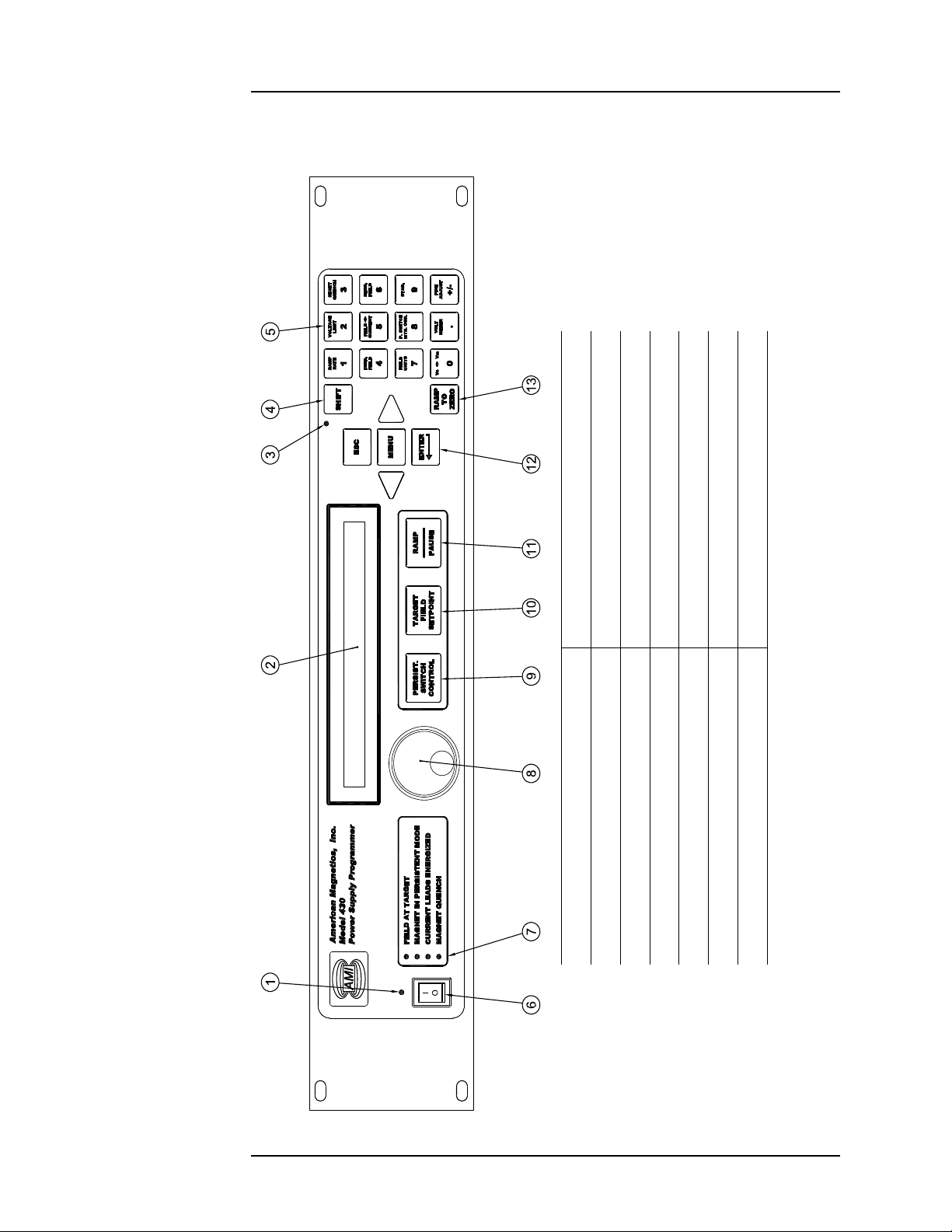
1 Power Indicator LED 8 Fine Adjust Knob
2 280 x 16 Dot Graphic VF Display 9 Persistent Switch Heater Control Key
3 Shift Indicator LED 10 Target Field Setpoint Key
4 Shift Key 11 Ramp/Pause Switch
5 4 Row x 3 Column Keypad 12 Menu Navigation and Data Entry Keys
6 Power Switch 13 Ramp to Zero Key
7 Magnet Status Indicator LEDs
Table 1-1. Model 430 Front Panel Description
Model 430 Front Panel
1.2 Model 430 Front Panel Layout
Rev. 5 5
Page 24
Introduction
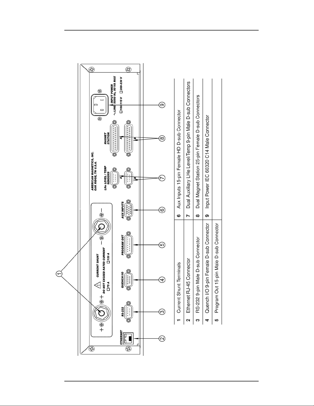
Table 1-2. Model 430 Resistive Shunt Version Rear Panel Description
Model 430 Rear Panel Layout
1.3 Model 430 Rear Panel Layout
6 Rev. 5
Page 25
Introduction
Power Supply Front Panel Layout
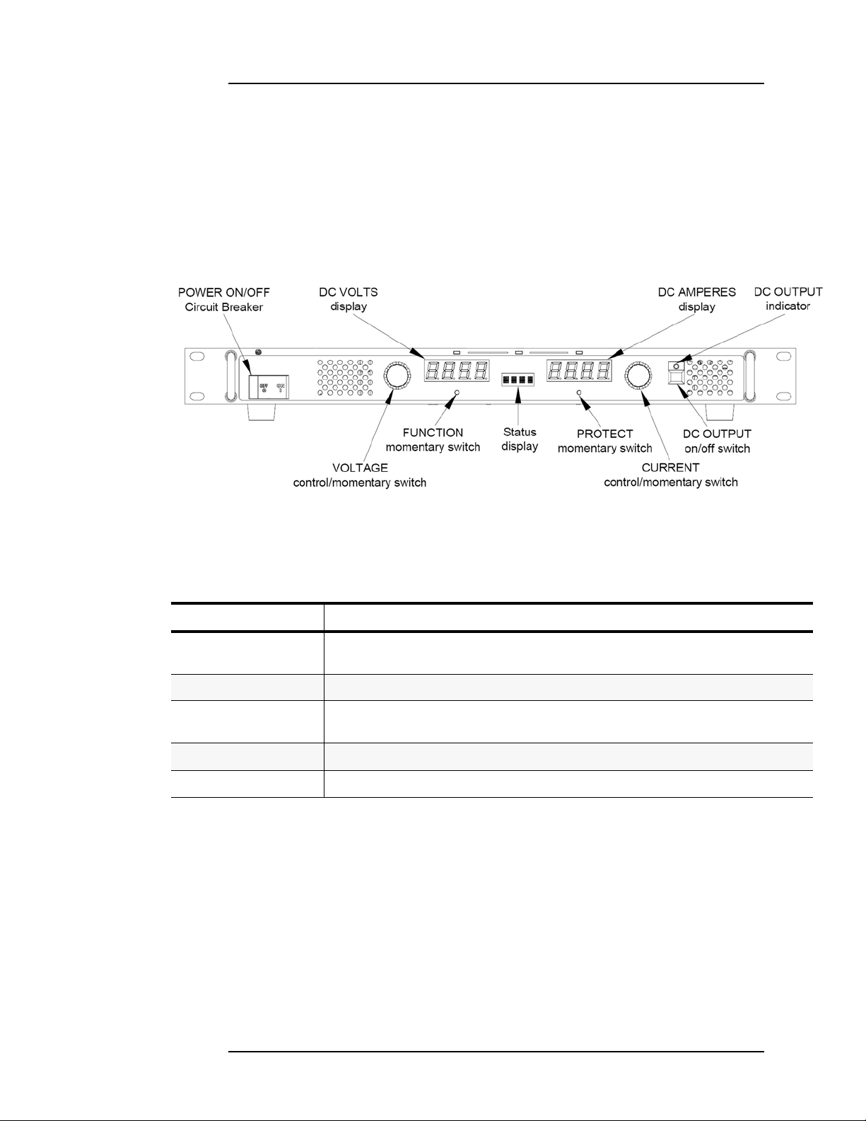
1.4 Power Supply Unit Front Panel Layout
The power supply front panel contains the input ON/OFF circuit breaker
and the OUTPUT indicators. The remaining front panel controls are not
used in the Model 05100PS-430-601 configuration because the output is
controlled by the Model 430 Programmer. Refer to Figure 1-2 and Table 1-
3. for a description of front panel controls and indicators.
Figure 1-2. Model 08150PS Front Panel
Table 1-3. Power Supply Front Panel Controls and Indicators
Control or Indicator Function
POWER ON/OFF
Circuit Breaker
DC VOLTS display Four-digit LED display that shows output voltage.
Status
4 character display
DC AMPERES display Four-dig it LED display that shows output current.
DC OUTPUT indicator Green LED lights when DC output is enabled. LED is off when output is disabled.
Turns the power supply on or off. Circuit breaker provides input overload protection.
Displays active function or blinks for error messages. N orm al l y bla nk.
Rev. 5 7
Page 26

Introduction
Figure 1-3. Model 601 Front Panel Layout
Model 601 Front Panel
1.5 Model 601 Energy Absorber Front Panel Layout
The Fault LED is the only device on the Model 601 front panel. If the Fault
LED is not energized, the Model 601 is operating correctly. If the Fault
LED is energized, then one or more of the internal energy absorbing
elements has malfunctioned or power has been lost to the rear-panel
power connector. An audible alarm will also sound when the Fault LED is
energized.
Caution
If the system is in operation when an energy absorber fault occurs, a
safe magnet system state (typically zero current or a cooled
persistent switch in a connected magnet) should immediately be
attained. Do not continue to operate the unit, and refer to the
“Troubleshooting Hints” on page 137 for further direction.
8 Rev. 5
Page 27

Introduction
Model 601 Front Panel
1.6 System Specifications @ 25°C
Magnet Current Control
Range: 0 to +100 A
Programming Accuracy: 40 mA
Stability: 20 mA after 20 min. at desired current
Minimum Ramp Rate: 100 μA/min
Maximum Ramp Rate: 10 A/sec
Output Voltage
Range: 0 to ±5 Vdc
Measurement Resolution: 10 mV
Load Inductance
Range: 0.5 to 100 H
Primary Power Requirements
Physical
Dimensionsa:
Approximate Weight: 70 lbm (30 kg)
Terminal Torque Limit: 48 lbf-in (5.4 N-m)
Environmental Limits
Ambient Temperature: 0 °C to 40 °C (32 °F to 104 °F)
Relative Humidity: 0 to 95%; non-condensing
a. H = height; W = width; D = depth
Range: 100 - 115 or 200 - 230 Vac ±10%
50 / 60 Hz, 1500 VA
12.5” H x 21” W x 24.5” D
(318 mm H x 533 mm W x 622 mm D)
Rev. 5 9
Page 28
Introduction
20
-20
200-200
V
I
Positive Current
Flow Direction
Positive Voltage
Polarity
Positive Current
Flow Direction
Negative Voltage
Polarity
Negative Current
Flow Direction
Positive Voltage
Polarity
Negative Current
Flow Direction
Negative Voltage
Polarity
12
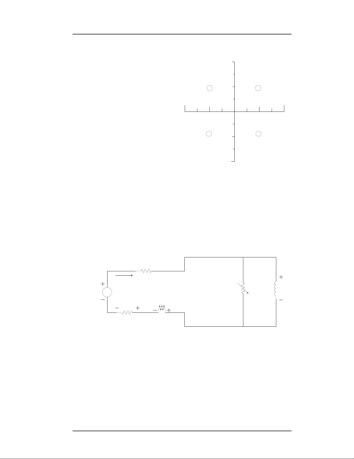
43
Figure 1-4. The Four Regions, or Quadrants, of System Operation.
Magnet
Coil(s)
Persistent
Switch
(optional)
Misc. Line Losses
Model 420
Shunt
Energy
Absorber
V
Unipolar
Power Supply
Current
Figure 1-5. Dual-Quadrant System with Resistive Shunt
430
Operating Characteristics
1.7 Operating Characteristics
The Model 430 Programmer has
been designed to perform with various power supplies to allow the
user the greatest degree of system
flexibility. The power supply and
Programmer combination are categorized by one of three forms: sin-
gle-quadrant, dual-quadrant, and
four-quadrant. For sake of clarity,
the term quadrant is defined as
one of four areas of a cartesian
coordinate system where the
abscissa is current and the ordinate is voltage. Refer to Figure 1-4.
1.7.1 Dual-Quadrant Operation
In the Model 05100PS-430-601 dual-quadrant Power Supply system, an
energy absorber is added in series with the unipolar supply; this allows
stored magnetic energy to be converted to thermal energy, thereby
allowing much faster magnetic field reduction. This corresponds to
operation in quadrants 1 and 4 of Figure 1-4. The disadvantage to this
type of system is that energy is being dissipated in the energy absorbing
element whenever current is flowing. This loss is sometimes a significant
portion of the power required to operate the system.
10 Rev. 5
Page 29

2 Installation
Warning
Before energizing the equipment, the earth ground of the power
receptacle must be verified to be at earth potential and able to carry
the rated current of the power circuit. Using extension cords should
be avoided; however, if one must be used, ensure the ground
conductor is intact and capable of carrying the rated current.
In the event that the ground path becomes less than sufficient to
carry the rated current of the power circuit, the equipment should be
disconnected from power, labeled as unsafe, and removed from place
of operation.
Do not operate this equipment in the presence of flammable gases.
Doing so could result in a life-threatening explosion.
Do not modify this equipment in any way. If component replacement
is required, return the equipment to AMI facilities as described in
the Troubleshooting section of this manual.
If used in a manner not specified in this manual, the protection
provided by the design, manufacture and documentation of the
system may be impaired.
2.1 Inspecting and Unpacking
Carefully remove the equipment, interconnecting cabling, and
documentation CD (and/or printed material) from the shipping carton, and
remove all packaging material.
Note
If there is any shipping damage, save all packing material and
contact the shipping representative to file a damage claim. Do not
return to AMI unless prior authorization has been received.
2.2 Power Supply System Mounting
If the system is to be used on a table top, place the equipment on a flat,
secure surface.
Rev. 5 11
Page 30

Installation
Power Requirements
2.3 Power Requirements
Warning
The power requirement for each system component is marked on the
rear panel of the unit adjacent to the power entry connectors. Be sure
the power supply system is configured for the proper power source
prior to plugging in the line cords. Do not fail to connect the input
ground terminal securely to an external earth ground.
Ensure the front panel power switches are in the OFF (
that the power supply components are configured for the proper operating
voltage by referring to the equipment rear panels. If the operating voltage
is correct, plug the line cords into power entry connectors, and into the
appropriate power receptacles.
O) position. Verify
2.3.1 Changing the Model 430 Programmer Operating Voltage
Warning
The following procedure is to be performed only when the Model 430
Programmer is completely de-energized by removing the power-cord
from the power receptacle. Failure to do so could result in personnel
coming in contact with high voltages capable of producing lifethreatening electrical shock.
Note
The voltage selector switch is labeled “115” for nominal line voltages
from 100 to 115 VAC. The switch is labeled “230” for nominal line
voltages of 200 to 230 VAC.
If the Model 430 Programmer operating voltage must be changed, ensure
the instrument is de-energized by disconnecting the power cord from the
power source. Remove the Model 430 Programmer cover by removing the
four screws on both sides of the cover and the four screws from the corners
of the cover on the back panel; slide the voltage selector switch on the main
printed circuit board to the proper voltage. Replace the Model 430
Programmer cover.
2.4 Collecting Necessary Information
In order to properly configure the Model 430 Programmer, specific system
information is required. Such parameters as the magnet electrical
properties, type of power supply, persistent switch heating current
requirements, and voltage and current constraints of the magnet are
entered into the Model 430 Programmer once and nonvolatile memory will
retain the data even after power is removed from the instrument. An
12 Rev. 5
Page 31

Installation
Power Requirements
example of the data to be entered and how it is entered is described in
section 3.11 on page 74.
If the Model 430 Programmer was purchased as part of a magnet system,
essential data will have already been entered at the AMI factory and a
configuration sheet will have been provided detailing the settings.
2.5 System Interconnects
If the Model 430 Programmer was purchased as part of a magnet system,
all applicable system components and wiring harnesses will have been
shipped with the system.
The diagrams that follow will assist in system equipment setup.
Caution
The wiring between the power supply and the magnet current leads
must be of sufficient size to carry the full rated current of the power
supply. Typically, for short runs (less than 25 ft, or 7.6 m), 2 AWG
wire is sufficient for 125 A current, and 2/0 AWG wire is best for
250 A current.
Note that an AMI Model 13x Liquid Helium Level Instrument is shown as
a possible component of each integrated system. The main
instrumentation cable connecting the magnet support stand to one of the
Model 430 Programmer
instrumentation and control connections needed to control and monitor
the magnet. The signals in this cable which are required to monitor LHe
level and temperatures are also presented at the LHe Level / Temp
Connectors. Refer to the Appendix for pin-outs of these and other
connectors.
MAGNET STATION connectors contains all the
2.5.1 Model 05100PS-430-601 Bipolar Supply
For the bipolar (dual-quadrant) mode with shunt method of current
sensing, the magnet power supply system consists of the Model 430
Programmer, a unipolar 08150PS Power Supply, a Model 601 Energy
Absorber, and associated interconnection cabling and buswork. Figure 2-1
Rev. 5 13
Page 32

Installation
Figure 2-1. Typical Model 05100PS-430-601 System Rack Interconnections
Power Requirements
and Figure 2-2 on page 15 depict the 05100PS-430-601 integrated power
supply system interconnects.
Refer to Figure 2-2 on page 15. Ensure the cabling is connected in the
following manner:
Note
The use of locking hardware is recommended for all high-current
connections.
Caution
Do not overtighten the hardware on the interconnection terminals
(refer to specifications table on page 9 for torque limits).
Overtightening can result in damage to the terminals.
Warning
Ensure the protective diode is installed across the output terminals
of the power supply with the anode at the negative (–) terminal and
the cathode at the positive (+) terminal. Removal or omission of this
protective diode may cause serious injury to personnel and damage
to the power supply under loss of AC power conditions.
14 Rev. 5
Page 33

Installation
!
Superconducting
Magnet
Model 430 Rear Panel
1
2
3
4
5
6
8
9
LINE VOLT AGE , 1A M A X
CONTROLLER OUTPUT
COMMUNICATIONS
50-60 Hz (SEL. SW. INSIDE)
J2
AMERICAN MAGNETICS, INC.
OAK RIDGE, TN U.S.A.
INPUT POWER
RS-232
J8
S11
ON
90-132 VAC 180-264 VA C
SENSOR
J1
!
!
AMI Model 13x Rear Panel
Model 08150PS Unipolar
Supply Rear Panel
7
10
1112
15
13
14
16
Model 601 Energy
Absorber Rear Panel
17
17
Figure 2-2. Model 05100PS-430-601 Bipolar System Interconnections
Power Requirements
Rev. 5 15
Page 34

Installation
Power Requirements
a. Connect the protective diode between the output terminals of the
power supply: anode to the negative (–) terminal and the cathode to
the positive (+) terminal.
b. Connect the positive (+) output terminal (1) of the power supply to
the Model 601 Energy Absorber positive (+) terminal (2).
c. Connect the negative (−) terminal (3) of the Model 601 Energy
Absorber to the positive (+) magnet current lead (4).
d. Connect the negative (−) magnet current lead (5) to the positive (+)
resistive shunt terminal (6) on the back of the Model 430
Programmer.
e. Connect the negative (−) resistive shunt terminal (7) of the Model
430 Programmer to the negative (–) output terminal of the power
supply (8).
f. Connect two jumpers (17) from terminal block position S- to M- and
from S+ to M+ on the power supply unit.
g. Connect the DB15 analog I/O cable from the
PROGRAM OUT
connector (14) on the back of the Model 430 Programmer to the
DB15
ANALOG I/O connector (9) on the rear of the power supply
unit.
h. Install an instrumentation cable between the magnet support
stand top plate connector (10) and one of the
MAGNET STATION
connectors (16) on the rear of the Model 430 Programmer.
i. Optional: Install an instrumentation cable between one of the
LEVEL / TEMP
connectors (15) on the rear of the Model 430
LHe
Programmer and the Model 13x Liquid Helium Level Instrument
and/or temperature instrument (11). Refer to section A.2 on page
150.
j. Optional: Install an instrumentation cable between the
I/O
connector (13) on the rear of the Model 430 Programmer and
Aux connector
J2 (12) on the rear panel of the Model 13x Liquid
QUENCH
Helium Level Instrument. Refer to section A.5.2 on page 154.
k. Connect Model 601 power adapter (17) and device line cords, and
plug them into appropriate power receptacles.
l. Remote communications via Ethernet and/or RS-232 can be
accomplished by connecting suitable cabling to the Model 430
Programmer rear panel
16 Rev. 5
ETHERNET and/or RS-232 connectors.
Page 35

Installation
Magnets w/o Persistent Switch
2.6 Special Configurations
The Model 430 Programmer has been designed for optimal operation with
a superconducting magnet (i.e. a very low resistance, high inductance
load) with a persistent switch. The Model 430 Programmer is capable of
controlling current to other loads; however, some modification to the
Model 430 Programmer settings and/or connections must usually be made.
Two commonly encountered configurations are: 1) superconducting
magnets without a persistent switch, and 2) operation on a short-circuit or
low resistance load.
2.7 Superconducting Magnets with No Persistent Switch
An external stabilizing resistor for superconducting magnets without a
1
persistent switch is no longer required
. However, these systems do
require a specific Model 430 Programmer stability setting based on the
magnet inductance as follows:
For magnet inductance
<= 100 Henries (H):
Stability Setting = (100 - H)
For magnet inductance
> 100 Henries:
Stability Setting = 0
2.8 Short-Circuit or Resistive Load
If operating with a short-circuit as a load without the presence of a
superconducting magnet, the Model 430 Programmer must be manually
configured for stability. Normally, when the persistent switch heater is
deactivated, the Model 430 Programmer sees essentially a short-circuit
load since the persistent switch shunts all current flow away from any
connected magnet. Therefore, one method of operating a short-circuit is to
indicate that a persistent switch is present, with the persistent switch
heater deactivated.
The preferred method
is to indicate that a persistent switch is not present
(see section 3.10.2.6 on page 56) and adjust the stability setting (see
section 3.10.2.1 on page 50) to control the load. A stability setting of 100%
will always allow control of a short-circuit as the load, regardless of the
state of the persistent switch heater.
If the resistance of the load is increased, the stability setting must be
decreased to improve the transient response of the system. If the current
1. Effective with Model 430 firmware version 1.62.
Rev. 5 17
Page 36

Installation
Power-Up Procedure
appears to lag, then decrease the stability setting until the system is
responsive. If the current appears to oscillate, increase the stability setting
until the oscillations are damped.
Note
If you have purchased a superconducting magnet with the Model
430 Programmer, AMI will normally provide a recommended
stability setting for optimal operation of the magnet system. If you
operate the Model 430 Programmer with a different load, be sure to
restore the stability setting to the recommended value when the
superconducting magnet is reconnected.
The stability setting is essentially manual control of the gain of an
integrator present in the control logic of the Model 430 Programmer.
Increasing the stability setting decreases the gain of the integrator.
A special case is with the energy absorber designs available from AMI. The
Model 601 Energy Absorber is a nearly infinite-resistance device until 5
Vdc is achieved across its terminals. Once the 5 Vdc “bias” is present, the
Model 601 allows current flow with a nominal 2 mΩ series resistance.
Therefore, the Model 430 Programmer will require an “integration time” to
overcome the 5 Vdc bias. Once the bias is achieved, the series resistance is
minimal and the Model 601 appears as a short-circuit. It is not possible to
decrease the stability setting to remove the integration time, since once
the 5 Vdc bias is achieved, the load is a short-circuit and the system will
become unstable.
However, when operating with a superconducting magnet in the circuit,
the integration gain of the Model 430 Programmer will be adequate to
quickly “bias” the Model 601 and achieve a proper current ramping profile.
The only time the “integration time” is long is when an energy absorber is
used, and the load is a short circuit.
2.9 Power-Up and T est Procedure
It is important to verify that the magnet system has been properly
connected before the superconducting magnet is energized. This is
especially recommended if the system is to be controlled via a computer
since this setup will allow software debugging without the potential for
damage to the magnet. The following procedures will assist the user in the
verifying key system components.
1. Using the appropriate diagram from section 2.5 as a guide, verify
all system components are connected as shown. If there is any
doubt as to the correct connection of a component, contact an AMI
Technical Support Representative. The user may be required to
18 Rev. 5
Page 37

Installation
Power-Up Procedure
properly make a few connections between the various system
components which were disconnected to facilitate packing and
shipping.
2. Temporarily place a short across the magnet current terminals.
Often this is most easily accomplished by unfastening the heavy
cables from the magnet current leads and fastening them together.
This will allow rudimentary power supply checks without
energizing the superconducting magnet.
3. Energize the Model 430 Programmer by placing the power switch
in the I (ON) position.
Note
Ensure the Model 601 energy absorber power adapter is properly
connected to the energy absorber and the AC power receptacle.
4. When prompted by the Model 430 Programmer, energize the power
supply and press ENTER on the Model 430 Programmer.
1
Note
Remember to adjust the programmer Voltage Limit settings as
necessary to account for the additional voltage (5 V) required to
operate the system with a Model 601 installed.
Warning
All power supply parameters, both hardware and software, have
been set at the AMI factory. Power supply control, with the exception
of powering
Power Supply Programmer. No field adjustments or reconfiguration
of the power supply should be attempted in the field unless
specifically described in this document or recommended in writing
by an AMI Technical Support Representative.
5. Enter a stability setting of 100%. Refer to sections 3.3 on page 27
and 3.7.9 on page 41.
6. Verify the various setup menu values for the system (with the
exception of the stability setting, which is to be temporarily left at
100%). If the power supply system was purchased with an AMI
magnet, AMI has preset the setup menu values for proper
operation. See sections 3.3, 3.5, 3.9 and 3.10 for more discussion of
ON and OFF, is done by way of the AMI Model 430
1. If the system shipped with CamLoc quick-disconnect connectors, they may be
quickly disconnected from the magnet leads and connected together.
Rev. 5 19
Page 38

Installation
Power-Up Procedure
the setup menu values and their entry into the Model 430
Programmer.
7. Set the Model 430 Programmer to display current (rather than
field). Refer to sections 3.2.1 and 3.7.5.
8. Set the ramp rate to 1 A/sec. Refer to sections 3.3 on page 27 and
3.7.1 on page 35.
9. Set the target current to 10 A. Refer to sections 3.3 on page 27 and
3.6.2 on page 33.
10. If a Persistent Switch is installed, set the PSw P/S Ramp Rate to 10
A/sec. Refer to paragraph 3.10.2.11 on page 58
11. Initiate ramping to the target current by pressing the
PAUSE
key (status indicator changes from P to ).
RAMP /
12. The system should ramp to 10 A in approximately 10 seconds.
Verify this is the case (if a PSwitch is installed and in the cooled
state, ramp time to 10 A should be slightly less than 2 seconds).
Note
With an energy absorber unit is connected, the Model 430
Programmer may take significantly longer to ramp the current to 10
A. The Model 430 must first develop a supply output voltage to
overcome the forward voltage drop of a connected energy absorber.
During actual magnet operation, the presence of an energy absorber
will not significantly delay the ramping operation since the Model
430 control gain is increased by orders of magnitude when an
inductive load is connected (unless stability setting is 100%).
13. When the target current is achieved, the
will be illuminated. The display should show “
indicating that the Model 430 Programmer is in the holding mode
at the target current value (+10.00 A).
FIELD AT TARGET LED
+10.00 A -”
Note
There may be a discrepancy between the current shown on the power
supply display
Programmer. The current measurement system incorporated in the
Model 430 is more accurate than the power supply shunt.
1. Not all power supplies have a local current readout.
20 Rev. 5
1
and the current displayed on the Model 430
Page 39

Installation
Power-Up Procedure
14. Verify that the power supply output current display indicates that
a total of approximately 10 A is being supplied to the load (which is
only the cabling in this case).
15. Set the target current to the Current Limit value. Refer to section
3.10.2.4 on page 54 to determine the Current Limit value. After the
new target current value is entered, the Model 430 Programmer
should ramp automatically to the new setting.
16. When the new target current value is reached, the power supply
current display (if provided) should also indicate the new value.
17. Press the
RAMP TO ZERO key to ramp the system to zero current.
18. Perform remote control software checkout as required.
19. Turn off the power supply.
20. Reset the stability setting and ramp rate of the Model 430
Programmer to an appropriate value for the magnet to be operated.
Then turn off the Model 430.
21. Remove the short from the power supply leads and connect the
leads to the magnet current leads of the magnet.
After successful completion of this test, the system is ready for operation
with a superconducting magnet. Refer to the ramping function example
presented in section 3.14 on page 87 for a discussion of the various
available ramping methods.
Rev. 5 21
Page 40

Installation
Power-Up Procedure
22 Rev. 5
Page 41

3 Operation
+0.00 A - Turn on power supply
+0.00 Vs Press ENTER to continue
This section describes the operation of the Model 430 Programmer. Every
menu and submenu item is illustrated and described in detail. An example
setup of the Model 430 Programmer is presented in section 3.11 on
page 74. An example ramping operation is presented in section 3.14 on
page 87.
Note
In some of the examples and figures that follow, the ± sign is used to
described various controlled parameter values such as current,
voltage, ramp rate, etc. Where used to describe voltages, currents,
and fields as relate to the Model 05100PS-430-601 Power Supply,
the ± should be ignored (considered illustrative only) since the power
supply provides only positive (unipolar) current.
3.1 System Power On/Off Sequence
The Model 430 Programmer should always be energized before the power
supply that it is controlling. The Model 430 Programmer is designed to
prompt the user in order to ensure the power supply is energized at the
proper time. The Model 430 Programmer should always be de-energized
after the power supply is shut down.
3.1.1 Model 430 Programmer Power On/Off
Place the Model 430 Programmer power switch in the ON position. After
the Model 430 Programmer is powered on and fully initialized (about 20
seconds), the following display will appear:
After this screen is displayed, the power supply can be powered up (See
“Energizing Power Supply and Components” on page 24.) followed by
pressing the
the default display
ENTER key on the Model 430 Programmer. This brings up
1
.
1. Refer to section 3.2 on page 25.
Rev. 5 23
Page 42

Operation
AMI Model 430 Programmer
FAILURE TO LOAD.
Energizing Power Supply System Components
Note
If turned off, the Model 430 Programmer must remain unpowered
for at least 5 seconds
be an initialization error, in which case the following screen will be
displayed.
If this occurs, turn the Model 430 Programmer off, wait 15 seconds
or more, and power the Model 430 Programmer back on.
When powering the system off, first turn off the power supply controlled by
the Model 430 Programmer followed by the Model 430 Programmer. The
controller will then ensure the load sees no abnormal power transients as
the power supply is turning off.
before it is powered back on. If not, there may
3.1.2 Energizing Power Supply and Components
Warning
Do not change power supply jumpers, dip-switches, or other factory
settings. If not rack-mounted, always position power supply and
Model 601 Energy Absorber for convenience in disconnecting the
power cords.
3.1.2.1 Power Supply
Place the power supply switch in the ON position. No local (front
panel) adjustments or connections are required since the power
supply control mode and other parameters have been factoryconfigured for control by the AMI Model 430 Power Supply
Programmer.
When powering the system off, turn OFF the power supply before
powering off the Model 430 Programmer.
3.1.2.2 Energy Absorber
The Model 601 Energy Absorbers is operational immediately upon
connection to a power receptacle. Power is supplied to the Model
601 by connecting the supplied external DC power converter to the
matching connector at the rear of the Model 601, and then
connecting the AC power cord to the appropriate power receptacle.
24 Rev. 5
Page 43

Operation
+50.00 A — Status: Holding
+0.50 Vs PSwitch Heater: ON
+50.00 A — -10 0Vm +10
+1.50 Vs |''''|''''|''''|'''''|
Field / Current Display.
Default display showing ramp mode and persistent switch heater status:
Default display showing voltmeter:
Figure 3-1. Default Display.
Voltage Display.
Status Indicator.
Main Display.
Default Display
3.2 Model 430 Programmer Default Display
The default display is illustrated in the figure below. It is displayed
whenever no menus are being accessed and no errors are being indicated.
The default display can be thought of as being logically divided into four
display areas — the Field / Current Display area, the Voltage Display
area, the Status Indicator area and the Main Display area.
3.2.1 Field / Current Display
The field / current display indicates either the field strength or current1.
This is always displayed in the upper left corner of the display (see Figure
3-1), regardless of what else is being displayed on the Model 430
Programmer display. The parameter displayed (field or current) is toggled
by pressing
is being displayed, pressing
SHIFT followed by FIELD <> CURRENT. Thus, if field strength
SHIFT followed by FIELD <> CURRENT will
cause the current to be displayed; conversely, if current is being displayed,
pressing
strength to be displayed. Operating current is always displayed in
amperes (A). Operating field strength may be displayed in kilogauss (kG)
or tesla (T) if a coil constant has been specified in the setup
strength is being displayed, the units (kG or T) in which it is displayed can
be toggled by pressing
SHIFT followed by FIELD <> CURRENT will cause the field
SHIFT followed by FIELD UNITS.
1. The value is always displayed in current (A) when an installed persistent switch is in
the cooled state since the value represents power supply current only, independent
of magnet current/field.
2. Refer to section 3.10.2.2 on page 52.
2
. If field
Rev. 5 25
Page 44

Operation
Table 3-1. Description of
Status Indicators
P
Paused
Ramping Up
Ramping Down
– Holding
Heating Persistent Switch
Cooling Persistent Switch
V
Voltage Limit
Default Display : Voltage
Note
Note that the displayed field strength is not directly measured, but
rather is calculated by multiplying the coil constant entered in the
setup menu by the measured current flow of the Model 430 power
supply system.
3.2.2 Voltage Display
The voltage display indicates either the voltage across the magnet (Vm) or
the power supply output voltage (Vs). This is always displayed in the lower
left corner of the display (see Figure 3-1), regardless of what else is being
displayed on the Model 430 Programmer display. The parameter displayed
(magnet voltage or power supply voltage) is toggled by pressing
followed by
Vs <> Vm. Vm indicates the voltage measured across the
terminals of the connected superconducting magnet. In order for the Model
430 Programmer to measure the magnet voltage, the magnet voltage taps
must be connected to the Model 430. Normally this is done through the
Magnet Station Cable provided by AMI (if the whole magnet system is
provided by AMI). Vs indicates the Model 430 Programmer-controlled
power supply output voltage.
SHIFT
Note
Note that the displayed power supply voltage (Vs) is not directly
measured, but rather is calculated based on power supply control
voltage being provided by the Model 430 Programmer and the power
supply input control voltage and output voltage values entered in
the setup menu.
3.2.3 Status Indicator
The status indicator indicates the
Model 430 Programmer operating
status. It is always visible (except
during a quench condition) and is
displayed just to the right of the
field / current display (see Figure
3-1). The status indicator may be
one of six symbols indicating one
of the seven states shown in Table
3-1.
If the ramping mode character is
blank, then a quench condition
exists and the red MAGNET
QUENCH indicator in the status
section of the front panel will be
illuminated. See section 3.12 on page 77 for a detailed discussion of the
26 Rev. 5
Page 45

Operation
Figure 3-2. Numeric Keypad and Associated Keys
Default Display : Main
meaning of the ramping modes (Paused, Ramping Up, Ramping Down and
Holding).
3.2.4 Main Display
The default main display (the rightmost portion of the display – see Figure
3-1) shows either a voltmeter indicating magnet voltage or ramp mode and
persistent switch heater state. Ramp mode is displayed on the top line of
the main display; it will be one of eight states, as shown in Table 3-6 on
page 78. Persistent switch heater state is displayed on the bottom line of
the main display. If the Model 430 Programmer has been setup for use
with a persistent switch, it will indicate either ON or OFF for the
persistent switch heater state; otherwise, it will display “No PSwitch
Installed.”
3.3 Entering Numeric Values
A consistent method of entering values is used within menus requiring
numeric entries. Once a menu is selected, the user may start an entry by
pressing a digit (
0 through 9), the decimal key (.), or the sign key (+/-).
The display will begin a new entry and display a cursor (_) as a prompt for
the next digit or decimal entry. Also, once entry is initiated, the display
will show an asterisk (*) indicating that numeric entry is active.
Alternately, the
ENTER key may be pressed before any of the numeric
keypad keys; the display will begin a new entry and display a cursor (_) as
a prompt for the next digit or decimal entry, and the display will show an
1. Certain menu items requiring numeric data can also be entered using the fine
adjust knob (see section 3.4 on page 28).
Rev. 5 27
1
Page 46

Operation
+50.00 A - Target Current (A)*
+0.50 Vs +74_
Fine Adjust Knob Operation
asterisk (*) indicating that numeric entry is active. An example of a
numeric entry in progress (numeric entry active) is illustrated below:
Once the numeric value has been entered, press the
the numeric value. Values are not applied to the operation of the Model
430 Programmer until the
disappears from the display. Attempts to set a parameter to a value
outside of the valid range are ignored, and if attempted the Model 430
Programmer will beep once indicating an error and revert to the previous
setting.
If the
been entered, the entered digits will be cleared and the cursor will remain
for reentry of a new desired value. If the
entered digits on the display, the setting will revert to the previous value
and numeric entry will be made inactive. Thus, if digits have been entered,
the first time
entry remains active; if
displayed), the setting reverts to its previous value and numeric entry is
made inactive. Note that if the
not active, the current submenu will be exited and the next higher level
submenu will be entered.
ESC key is pressed while numeric entry is active and digits have
ESC is pressed, the entered digits are cleared, but numeric
ENTER key is pressed and the asterisk
ESC key is pressed with no
ESC is then pressed again (with no entered digits
ESC key is pressed when numeric entry is
ENTER key to accept
3.4 Using Fine Adjust Knob to Adjust Numeric Values
For menu items requiring entry of a numeric value, the value may
alternatively be adjusted with the front panel fine adjust knob. These
menu items include:
• Target Field Setpoint (in holding mode or while ramping)
•Voltage Limit
• Ramp Rate (if there is no PSwitch or if PSwitch is fully heated).
Disallowed during switch heating/cooling transition.
• Custom Supply Menu (Min Output Voltage, Max Output Voltage,
Min Output Current, Max Output Current)
• Stability
• Coil Constant
• Current Limit
• Magnet Current Rating
28 Rev. 5
Page 47

Operation
+50.00 A - PSwitch Current (mA)
+0.50 Vs 46.7
Entering Picklist Values
• PSw P/S Ramp Rate if PSwitch is fully cooled. Disallowed during
switch heating/cooling transition.
• PSwitch Current
• PSwitch Heated Time
• PSwitch Cooled Time
• PSwitch Cooling Gain
• Quench Rate
Instead of entering a value using the numeric keypad,
followed by
indicating that the fine adjust knob is active.
When the fine adjust knob is live, adjustments made using it take place
immediately. This is a very useful and powerful functionality. Any
numeric value can be incrementally adjusted using the fine adjust knob,
and its affect on the system can be observed as the adjustment is being
made. For example, with the persistent switch heater on, the persistent
switch heater current can be adjusted incrementally to find the persistent
switch heater superconducting/normal thresholds. An example of a fine
adjust in progress (fine adjust knob is live) is illustrated below:
FINE ADJUST. The display will show an up/down arrow ( )
SHIFT is pressed,
Note
The fine adjust knob is velocity-sensitive, meaning that the faster the
knob is turned, the more coarse the adjustment. Slow manipulation
of the knob will yield very fine resolution even beyond that displayed
by the Model 430 Programmer.
When the desired numeric value has been set using the fine adjust knob,
ENTER key is pressed to store the value. Pressing the ESC key while
the
the fine adjust knob is live will cause the adjusted value to revert to its
previous setting and make the fine adjust knob inactive. In fact, pressing
any key other than
previous setting and make the fine adjust knob inactive.
ENTER will cause the adjusted value to revert to its
3.5 Entering Picklist Values
Some submenu items require the user to select a value from a list of
predefined values (picklist values). Such menus will display an item
selector ( ) which points to the picklist value currently selected. To
change the value to another value in the picklist, first press the
Rev. 5 29
ENTER
Page 48

Operation
Figure 3-3. Menu Navigation Keys
+50.00 A - Field Units*
+0.50 Vs Kilogauss Tesla
Single-key Commands
key; the display will show an asterisk (*) indicating that picklist entry is
active.
While picklist entry is active, the left and right keypad arrows (to the left
and right of the
picklist values. Pressing the left keypad arrow moves the item selector one
picklist value to the left and pressing the right keypad arrow moves the
item selector one picklist value to the right. When the last picklist value is
reached, and the right keypad arrow is pressed, the item selector will move
to the first picklist value. Likewise, when the item selector is pointing to
the first picklist value, and the left keypad arrow is pressed, the item
selector will move to the last picklist value. An example of a picklist entry
in progress (picklist entry active) is illustrated below:
MENU key) move the item selector between the different
When the item selector is pointing at the desired picklist value, press the
ENTER key to accept the picklist value. Values are not applied to the
operation of the Model 430 Programmer until the
and the asterisk disappears from the display.
If the
revert to the previous value and picklist entry will be made inactive. Note
that if the
current submenu will be exited and the next higher level submenu will be
entered (if it exists).
ESC key is pressed while picklist entry is active, the setting will
ESC key is pressed when numeric entry is not active, the
3.6 Single-key Commands / Menu
All ramping controls (PERSIST. SWITCH CONTROL, TARGET FIELD
SETPOINT
single keystroke. See section 3.12 on page 77 for details of ramping
controls. Below is a brief summary of the function of each of these keys.
30 Rev. 5
, RAMP / PAUSE and RAMP TO ZERO) are accessed with a
ENTER key is pressed
Page 49

Operation
Figure 3-4. Single Input Keys
Single-key Commands : Persistent Switch Control
3.6.1 Persistent Switch Control Key
Pressing the PERSIST. SWITCH CONTROL key toggles the Model 430
Programmer persistent switch heater control function.
If the persistent switch heater is energized and this key is pressed, the
persistent switch heater is de-energized. The power supply is then
maintained for the time set by the PSwitch Cooled Time variable before
being ramped down to zero at the rate set by the PSw P/S Ramp Rate
variable (default rate is 10 A/sec).
If the persistent switch heater is de-energized and this key is pressed, the
power supply is ramped to the current present in the magnet when the
switch was cooled at the rate set by the PSw P/S Ramp Rate variable and
then the persistent switch heater is energized.
Pressing
SHIFT followed by the PERSIST. SWITCH CONTROL key toggles
the Model 430 Programmer persistent switch heater between energized
(turned on) and de-energized (turned off). If the persistent switch heater is
energized and this key is pressed, the persistent switch heater is deenergized. If the persistent switch heater is de-energized and this key is
pressed, the persistent switch heater is energized.
Note
The power supply current is unchanged when SHIFT + PERSIST.
SWITCH CONTROL is used. Only the state of the persistent switch heater
is changed.
When the persistent switch heater is energized, the Model 430
Programmer is supplying current to the appropriate pins (9 & 10) of the
Magnet Station Connectors in order to drive the persistent switch into a
normal state, which takes the magnet out of persistent mode. Magnet
persistent mode is indicated by the
1
LED
.
MAGNET IN PERSISTENT MODE
The Model 430 Programmer will beep once (indicating an error) if the user
attempts to activate the switch heater control without first indicating a
1. Refer to section 3.8.2.2 on page 42.
Rev. 5 31
Page 50

Operation
Single-key Commands : Persistent Switch Control
persistent switch is installed in the Load submenu and specifying the
1
switch heating current, heated time, and cooled time
.
The nominal switch heating current is listed on the magnet specification
sheet, and may be entered in the Model 430 Programmer by accessing the
Load submenu
2
. In addition to the heating current, the user must also
specify a heated time, cooled time, PSw P/S Ramp Rate and cooling gain.
The heated time allows the Model 430 Programmer to delay compensating
the internal control logic until the magnet is guaranteed to be in the
circuit. The heated time can be set from a minimum of 5 seconds to a
3
maximum of 120 seconds within the Load submenu
. The default heating
period of 20 seconds is adequate for the majority of persistent switches.
If the magnet appears unstable just after the switch heating period
expires, increase the switch heated time to allow for complete heating. The
cooled time allows the persistent switch sufficient time to be cooled to
superconducting state before the current is changed in the magnet. The
cooled time can be set from a minimum of 5 seconds to a maximum of 3600
4
seconds within the Load submenu
. The default cooling period of 20
seconds is adequate for the majority of wet persistent switches.
Conduction cooled switches typically require longer time to transition from
resistive to superconducting.
The default cooling gain of 0.0% may be adequate for the majority of wet
persistent switches. However, this setting may result in some magnet drift
during persistent switch cooling, especially with conduction cooled
switches. Increasing the cooling gain adds control loop gain during the
switch cooling cycle. Too little may result in magnet drift during switch
cooling. Too much may result in power supply instability during switch
cooling, which could potentially prevent the switch from cooling. Most
systems requiring some cooling gain to control magnet drift will likely
work with value set to 25%.
Note
During the period the switch is being heated or cooled, the Model
430 Programmer will not allow ramping functions to be executed
and will beep once if the user attempts to initiate a ramping
operation.
Refer to section 3.13 on page 79 for a complete description of magnet
persistent switch control. A flowchart of the persistent switch control
functions are located in the Appendix beginning on page 198.
1. Refer to section 3.10.2.6 on page 56, section 3.10.2.8 on page 57, section 3.10.2.9
on page 57, and section 3.10.2.10 on page 58.
2. Refer to section 3.10.2.8 on page 57.
3. Refer to section 3.10.2.9 on page 57.
4. Refer to section 3.10.2.10 on page 58.
32 Rev. 5
Page 51

Operation
+50.00 A - Target Field (kG)
+0.50 Vs +50.000
+0.25 A P Magnet Current (A)
+0.00 Vs +10.00 A
Single-key Commands : Target Field Setpoint
3.6.2 Target Field Setpoint Key
Pressing the TARGET FIELD SETPOINT key provides a menu for setting
the target field/current. The target field/current is the field or current to
which the Model 430 Programmer ramps the superconducting magnet
when it is not paused. The target field/current may be set to the lesser of
(1) the Magnet Current Rating, and (2) the Current Limit
field (per defined coil constant). The target field/current does not require a
sign (attempting to enter a negative value will cause the Model 430
Programmer to produce one beep to indicate an error).
1
or equivalent
When on the default display, pressing the
SETPOINT
three seconds before reverting to the default display. The value displayed
is as follows:
keys will temporarily display the Magnet Current/Field for
•When in driven mode, the present current/field will be displayed.
•When in persistent mode, the current/field will be displayed that
was flowing in the magnet at the time persistent switch was
cooled.
SHIFT + TARGET FIELD
3.6.3 Ramp / Pause Key
Pressing the RAMP / PAUSE key toggles the Model 430 Programmer
between the ramping mode and the paused mode. If the
key is pressed while the Model 430 is ramping, the ramping is paused. If
the
RAMP / PAUSE key is pressed while the Model 430 is paused, the
Model 430 continues ramping.
RAMP / PAUSE
3.6.4 Ramp To Zero Key
Pressing the RAMP TO ZERO key causes the Model 430 Programmer to
immediately begin ramping field/current up or down to zero field/current
at the defined ramp rate(s). Ramping to zero may be interrupted at any
time by pressing the
Programmer to enter the PAUSED mode and maintain the field/current
present at the point it was paused.
1. Refer to section 3.10.2.4 on page 54.
Rev. 5 33
RAMP / PAUSE key, which causes the Model 430
Page 52

Operation
Figure 3-5. SHIFT-Key Functions
Shift Key Commands
Note
If the RAMP TO ZERO function is PAUSED and then the RAMP /
PAUSE
will begin ramping to the target field, not to zero. If it is desired to
ramp to zero after the
RAMP TO ZERO button again to continue ramping to zero from the
paused state.
Note
If the magnet is persistent (persistent switch heater is not energized)
when the
Programmer ramps the power supply current to zero; the magnet
current will remain constant since the magnet is in persistent mode.
3.7 SHIFT-key Commands / Menus
button is pressed a second time, the Model 430 Programmer
RAMP / PAUSE button is pressed, press the
RAMP TO ZERO key is pressed, the Model 430
The most commonly used commands and menus (other than ramping
controls) are accessed using the
key. Use of the specific SHIFT-key commands and menus is described in
sections specific to the functionality of that specific SHIFT-key. In general,
a SHIFT-key command is executed or SHIFT-key menu is accessed by first
pressing the
pressing
1
The SHIFT-key command / menu for each key of the numeric keypad is
shown in light blue text at the top of each key. To access the voltage limit
1. Note the SHIFT key and the following keypad key-press are sequential, not simultaneous.
34 Rev. 5
SHIFT key followed by a numeric keypad
SHIFT key (which turns on the SHIFT LED), and then
one of the keys of the numeric keypad (0 through 9, “.”, or “+/-”).
Page 53

Operation
Shift Key Commands : Ramp Rate
menu, for example, press the SHIFT key, and then press the VOLTAGE
LIMIT
also be accessed using the setup menu.
key (also the 2 key). Note that some of the SHIFT-key menus can
Pressing the
ESC key or the SHIFT key a second time will clear the SHIFT
function and return the keypad to it's numeric function.
3.7.1 Ramp Rate SHIFT-key
Use of the RAMP RATE SHIFT-key provides a menu for setting ramp
rate(s). The ramp rate may be set
specific Model 430 Programmer configuration (refer to specifications on
page 9). If field units are being used, then the ramp rate setting is
displayed and set in units of kG/sec or T/sec). The allowable range is then
defined by the setting of the coil constant and the allowable range of the
ramp rate in terms of current as specified in the table on page 9. If the
2
Ramp Segments value
is greater than 1, then the menu also allows
setting of the field or current range for which each ramp rate is to be used.
The Model 430 Programmer will ramp at the specified rate if the available
compliance of the power supply is sufficient and the Voltage Limit is not
exceeded. The Model 430 automatically decreases the ramp rate internally
during operation if either the available compliance of the power supply is
insufficient, or the Voltage Limit is active.
1
within the range specified for the
3.7.1.1 Ramp Rate SHIFT-key Example
An example (using a magnet with rated current of 60 A3) will
illustrate the use of the ramp rate menus. The example assumes
that the field/current units have been set to amperes. and the ramp
segments value has been set to 3. Segmented magnet current
ramping is chosen with rates as follows:
1. ±0.2 A/s from 0 to ±55 A
2. ±0.1 A/s from ±55 to ±58 A
3. ±0.05 A/s above ±58 A.
4
In the following discussion, the fine adjust knob
can optionally be
used for ramp rate adjustment if the persistent switch is heated (or
if no persistent switch is installed). If the user attempts to edit
ramp rate segments using the fine adjust knob while an installed
switch is cooled, the Model 430 Programmer will produce one beep
to indicate an error
1. Using numerical keys per section 3.3 on page 27 or the fine adjust knob (see
section 3.4 on page 28).
2. Refer to section 3.10.3.2 on page 61.
3. In this example, both the Current Limit and Magnet Current Rating are set at the
rated magnet current of 60 A.
4. Refer to section 3.4 on page 28.
Rev. 5 35
5
. Similarly, if the switch is heated (or no switch
Page 54

Operation
+50.00 A - Seg.1 Ramp Rate (A/sec)
+0.50 Vs ±0.2000
+50.00 A - Seg.1 Range (A)
+0.50 Vs 0.0 to ±55.0
+50.00 A - Seg.2 Ramp Rate (A/sec)
+0.50 Vs ±0.1000
+50.00 A - Seg.2 Range (A)
+0.50 Vs ±55.0 to ±58.0
Shift Key Commands : Ramp Rate
is installed), attempting to use the fine adjust knob for PSw P/S
ramp rate will produce one beep
Pressing
menu. The numeric and
used to set the segment 1 ramp rate to a value of 0.2.
The right arrow key is pressed once to access the segment 1 range
display. The numeric and
used to set the segment 1 current range upper bound to a value of
55.
Pressing the right arrow key accesses the next (second) segment
ramp-rate display. The segment 2 ramp rate is set to a value of 0.1.
SHIFT and then RAMP RATE will access the ramp rate
ENTER keys (or the fine adjust knob) are
ENTER keys (or fine adjust knob) are
1
.
The right arrow key is pressed once to access the segment 2 range
display. The segment 2 current range upper bound is set to a value
of 58.
5. Since the PSw P/S ramp rate is active in that scenario, and not the segmented
ramp rate.
1. Since the standard segmented ramp rate is active in that scenario, and not the PSw
P/S ramp rate.
36 Rev. 5
Page 55

Operation
+50.00 A - Seg.3 Ramp Rate (A/sec)
+0.50 Vs ±0.0500
+50.00 A - Seg.3 Range (A)
+0.50 Vs ±58.0 to ±Limit
Shift Key Commands : Ramp Rate
Pressing the right arrow key accesses the next (third) segment
ramp rate display. The segment 3 ramp rate is set to a value of
0.05.
Pressing the right arrow key accesses the segment 3 current range
display.
Note
Note that when there is more than one segment, the upper bound of
the last segment is always the Magnet Current Rating
Current Limit if set lower than the Magnet Current Rating); it will
be displayed as “±Limit” and cannot be edited.
Now, when current is in the range of 0 to ±55 A, ramping will be
controlled at ±0.2 A/s. When current is in the range of ±55 to ±58 A,
ramping will be controlled at ±0.1 A/s and when current is greater
than ±58 A (up to the limit of 60 A), ramping will be controlled at
±0.05 A/s.
If ramp rate of a ramp segment is being edited while the Model 430
is ramping and the system current/field transitions from the
currently edited segment to the next before the adjustment has
been committed with the
discarded. The display will update to show the new segment ramp
rate, and the fine adjust knob will apply to the new segment
(assuming the
completed).
ENTER key is pressed before the segment has
ENTER key, the adjusted value will be
1
(or the
If at some later time it is desired to temporarily set the Current
Limit to a new value lower than the Magnet Current Rating, for
example 56 A, this lower value will override the Magnet Current
Rating. Now only the first two ramp segments would be active since
1. Refer to section 3.10.2.4 on page 54 and section 3.10.2.3 on page 53.
Rev. 5 37
Page 56

Operation
+50.00 A - Seg.2 Range (A)
+0.50 Vs ±55.0 to ±Limit
+50.00 A - Seg.3 Range (A)
+0.50 Vs ±Limit to ±Limit
+50.00 A - Voltage Limit (V)
+0.50 Vs ±2.000
Shift Key Commands : Voltage Limit
the new “limit” falls within the range of segment 2. The display for
segment 2 range will now appear as follows
The unused segment(s) will remain in memory (retaining their
original parameters) until one or more become active again as the
Current Limit is raised into or above the respective ranges. When
displayed, the higher-range unused segments will show a range of
“±Limit to ±Limit” until re-activated
If the Current Limit is raised above the Magnet Current Rating, it
will be ignored and the actual Magnet Current Rating will govern.
3.7.2 Voltage Limit SHIFT-key
1
.
2
.
Use of the VOLTAGE LIMIT SHIFT-key provides a menu for setting the
limit for output voltage for the power supply the Model 430 Programmer
controls. This value should be set to a high enough value so that under
normal conditions, the Voltage Limit is never reached. The value can be
set by using either the numeric keypad per section 3.3 on page 27 or the
fine adjust knob (section 3.4 on page 28). Note that the voltage drop in the
leads must be accounted for when setting the Voltage Limit, as well as the
voltage drop of an energy absorber if one is used (see section 3.12 on
page 77 for details of how to determine the appropriate Voltage Limit).
The Voltage Limit may be set less than or equal to the maximum output
voltage of the power supply.
1. If the value were to be set below 55 A, only segment 1 would be active, and would
display the upper bound of “±Limit”.
2. Also if the number of segments is increased, the new segments are added to the
upper end of the ramp range, and default to the ramp rate of the previous segment
with the range of +/-Limit to +/-Limit until set up.
3. Refer to Table 3-2 on page 47.
3
38 Rev. 5
Page 57

Operation
+40.92 A Mode: Ramping
+2.50 Vs
V PSwitch: ON
+0.00 A - Quench Detect @ +45.81 A
+0.00 Vs PSwitch Heater: ON
Shift Key Commands : Reset Quench
If Voltage Limit becomes active while ramping, it will be indicated by a
reverse illumination character “V” for the status indicator.
Once the Voltage Limit function becomes active, the current, and therefore
field, will no longer be ramping linearly with time as the voltage available
to charge the magnet will be reduced as the total loop voltage will be
limited. As the IR drop of the leads increased with current, the voltage
available to charge the magnet will be reduced.
3.7.3 Reset Quench SHIFT-key
The RESET QUENCH SHIFT-key is used whenever a quench detection has
occurred and is being indicated on the display (example shown below).
When a quench detection has occurred, the Model 430 Programmer will
respond to no further input until the
or until the quench condition is cleared by a remote command. See Refer to
section 3.15 on page 88.
RESET QUENCH SHIFT-key is used,
3.7.4 Increment Field SHIFT-key
The INCR. FIELD SHIFT-key is used to manually increase the field. This
is done at the defined ramp rate.
When the
ramping up. If the
current/field is manually ramping up), the ramping will be paused.
Alternately, the
ramping. Manual ramping will continue until paused or the Current
Limit
INCR. FIELD SHIFT-key is used, the current/field begins
INCR. FIELD SHIFT-key is used again (while the
RAMP / PAUSE key may be pressed to pause manual
1
or Magnet Current Rating is achieved.
3.7.5 Field <> Current SHIFT-key
The FIELD <> CURRENT SHIFT-key is used to toggle between the use of
field units, either kG (kilogauss) or T (tesla), and the use of current units
2
(A)
. If the Model 430 Programmer is using field units (either kG or T) and
1. Refer to section 3.10.2.4 on page 54.
2. The value is always displayed in current (A) when an installed persistent switch is in
the cooled state since the value represents power supply current only, independent
of magnet current/field.
Rev. 5 39
Page 58

Operation
+50.00 A - Field Units
+0.50 Vs Kilogauss Tesla
+50.00 A — PSwitch Current (mA)
+0.50 Vs 10.0
Shift Key Commands : Decrement Field
the FIELD <> CURRENT SHIFT-key is used, the Model 430 Programmer
will begin using current units (A). Conversely, if the Model 430 is using
current units (A) and the
Model 430 will begin using field units (either kG or T).
Note
FIELD <> CURRENT SHIFT-key is used, the
The Model 430 Programmer cannot use field units unless a valid
1
coil constant has been entered
.
3.7.6 Decrement Field SHIFT-key
The DECR. FIELD SHIFT-key is used to manually decrease the current/
field. This is done at the defined ramp rate.
When the
ramping down. If the
DECR. FIELD SHIFT-key is used, the current/field begins
DECR. FIELD SHIFT-key is used again (while the
current/field is manually ramping down), the ramping will be paused.
Alternately, the
RAMP / PAUSE key may be pressed to pause manual
ramping. Manual ramping will continue until paused or the Current
2
Limit
or Magnet Current Rating is achieved.
3.7.7 Field Units SHIFT-key
Use of the FIELD UNITS SHIFT-key provides a shortcut to the picklist
3
menu
kilogauss (kG) or tesla (T). The selected option also applies to remote
interface commands. The default setting is kilogauss.
for defining whether the field is specified and displayed in units of
3.7.8 Persistent Switch Heater Current SHIFT-key
Use of the P. SWITCH HTR. CUR. SHIFT-key provides a shortcut to the
4
menu
between 0.0 and 125.0 mA. The default value is 10.0 mA unless preset by
AMI to match a specific superconducting magnet.
40 Rev. 5
for setting persistent switch heater current. The value can be set to
1. Refer to section 3.10.2.2 on page 52.
2. Refer to section 3.10.2.4 on page 54.
3. Refer to section 3.10.3.4 on page 62.
4. Refer to section 3.10.2.8 on page 57.
Page 59

Operation
Shift Key Commands : Stability
3.7.9 Stability SHIFT-key
Use of the STAB. SHIFT-key provides a shortcut to the menu for defining
the Model 430 stability setting. The stability setting is specified in percent
and controls the transient response and stability of the system. The valid
input range is from 0.0 to 100.0%. The default value is 0.0% unless preset
by AMI to match a specific superconducting magnet.
See section 3.10.2.1 on page 50 for details of how to determine the stability
setting to use.
3.7.10 Vs <> Vm SHIFT-key
The Vs <> Vm SHIFT-key is used to toggle the voltage display between
display of the voltage across the magnet (Vm) and the power supply output
voltage (Vs). See section 3.2.2 on page 26 for details.
3.7.11 Volt Meter SHIFT-key
The VOLT METER SHIFT-key is used to toggle the main display between
display of a voltmeter indicating magnet voltage (Vm) or supply voltage
(Vs), and display of ramp mode and persistent switch heater state. See
section 3.2.4 on page 27 for details.
3.7.12 Fine Adjust SHIFT-key
The FINE ADJUST SHIFT-key is used to enable the use of the front panel
fine adjust knob to adjust numeric values. See section 3.4 on page 28 for
details.
3.7.13 Persist. Switch Control SHIFT-key
Refer to section 3.6.1 on page 31.
3.8 LED Indicators
The Model 430 Programmer has six front panel LED indicators. See figure
with Table 1-1 on page 5 for the location of these indicators.
3.8.1 Power-on Indicator
The green power-on LED indicates that the Model 430 Programmer is
powered on.
Rev. 5 41
Page 60

Operation
Figure 3-6. Magnet Status LED Indicators.
LED Indicators : Field At Target
3.8.2 Magnet Status Indicators
Four LEDs are grouped together to show the magnet status.
3.8.2.1 Field At Target Indicator
The green
FIELD AT TARGET LED indicates that the current is at
the target value. If the magnet is not in persistent mode (persistent
switch heater is on), then this is an indication that the magnet field
has reached the target value. If the magnet is in persistent mode,
then this is an indication that the current being supplied to the
magnet system has reached the target value.
3.8.2.2 Magnet In Persistent Mode Indicator
Caution
If the Model 430 Programmer power is turned off while the
persistent switch is heated, persistent switch heating will be lost and
the magnet will enter persistent mode. The Model 430 will not have
a record of that event. Therefore the MAGNET IN PERSISTENT
MODE LED state will be incorrect (remain
OFF) when the Model
430 Programmer power is restored.
Caution
If the Model 430 Programmer power supply system is powered off
and moved from one magnet system to another, the
PERSISTENT MODE
LED may not correctly indicate the state of the
magnet system until the first time the persistent switch heater is
turned off.
MAGNET IN
Also, should the magnet quench while the magnet is in persistent
mode and the Model 430 Programmer is off, the persistent mode
indicator LED will be incorrect when the Model 430 Programmer is
turned on again.
The green
the persistent switch heater is off, and that when it was turned off,
the magnet had greater than 100 mA of current flowing through it.
42 Rev. 5
MAGNET IN PERSISTENT MODE LED indicates that
Page 61

Operation
+0.00 A - Setup Mode (Select one)
+0.50 Vs Supply Load Misc
LED Indicators : Current Leads Energized
The state of this LED is kept in nonvolatile memory when the
Model 430 is powered off, so that the LED state is retained even
during a power cycle of the Model 430. Thus, the
PERSISTENT MODE
persistent and has at least some persistent field.
3.8.2.3 Current Leads Energized Indicator
LED is an indicator that the magnet is
MAGNET IN
The blue
least 100 mA of current is flowing in the Model 430 power supply
system output current leads.
3.8.2.4 Magnet Quench Indicator
The red
condition has been detected. See section 3.15 on page 88 for details.
CURRENT LEADS ENERGIZED LED indicates that at
MAGNET QUENCH LED indicates that a magnet quench
3.8.3 SHIFT Indicator
The green SHIFT LED indicates that the SHIFT key has been pressed, and
the next numeric keypad key pressed will actuate the shifted function
(shown in light blue) rather than the numeric keypad function. See
section 3.7 on page 34 for details of
SHIFT key use.
3.9 Setup Menu
Setup of the Model 430 Programmer requires the user to navigate the
setup menu. Navigation of the setup menu is very intuitive — quite
similar, for example, to the use of a cell phone menu.
3.9.1 Entering / Exiting Setup Menu
To enter the setup menu, simply press the MENU key. When in any of the
setup menus, pressing the
key toggles the Model 430 Programmer in and out of setup mode.
Alternately, if the top level setup menu is being displayed, pressing the
ESC key exits the setup menu.
MENU key will exit the setup menu. The MENU
3.9.2 Menu Navigation
Pressing the MENU key enters the menu structure at the top level. The
display will look approximately as shown below:
Rev. 5 43
Page 62

Operation
Setup Submenu
The item selector ( ) points to whichever submenu was last used. The left
and right arrows at the ends of the displayed submenu selections indicate
that there are other submenu selections off screen, to the left and/or right
of the submenu selections shown.
The left and right keypad arrows (to the left and right of the
MENU key)
move the item selector between the different submenu items. Pressing the
left keypad arrow moves the item selector one item to the left and pressing
the right keypad arrow moves the item selector one item to the right.
When the last item is reached, and the right keypad arrow is pressed, the
item selector will move to the first item. Likewise, when the item selector
is pointing to the first item, and the left keypad arrow is pressed, the item
selector will move to the last item.
Pressing the
pointing when the
ENTER key opens the submenu to which the item selector is
ENTER key is pressed. See sections 3.10.1 on page 45
through 3.10.5 on page 72 for detailed descriptions of each submenu.
Pressing the
ESC key exits a submenu and moves the next higher level
submenu if it exists. If the top level setup menu is being displayed,
pressing the
ESC key exits the setup menu.
3.10 Setup Submenu Descriptions
When a submenu is entered by selecting a submenu item and pressing
ENTER (see section 3.9.2 on page 43 for details of menu navigation), the
44 Rev. 5
Page 63

Operation
Figure 3-7. Setup Menu Structure
Setup Submenu : Supply
user will be able to edit parameters under that submenu. See setup menu
structure in Figure 3-7 below.
SETUP MENU
SUPPLY
SELECT SUPPLY
SELECT SUPPLYSELECT SUPPLY
SELECT SUPPLY
SELECT SUPPLY
AMI 12100PS
AMI 12200PS
AMI 4Q05100PS
AMI 4Q06125PS
AMI 4Q06250PS
AMI 4Q12125PS
AMI 10100PS
OTHERS…
CUSTOM
CUSTOM
CUSTOM
MIN OUTPUT
VOLTAGE
MAX OUTPUT
VOLTAGE
MIN OUTPUT
CURRENT
MAX OUTPUT
CURRENT
V-V MODE
INPUT RANGE
0 to -5
0 to +5
0 to +10
-5 to +5
-10 to +10
LOAD
STABILITY
SETTING
COIL
CONSTANT
CURRENT
LIMIT
MAGNET CURRENT
RATING
CALCULATE MAGNET
INDUCTANCE
PSWITCH
INSTALLED?
PSw CURRENT
DETECT
PSWITCH
CURRENT
PSWITCH
HEATED TIME
PSWITCH
COOLED TIME
PSWITCH
P/S RAMP RATE
PSWITCH
COOLING GAIN
ENABLE QUENCH
DETECT?
ENERGY ABSORBER
PRESENT?
EXTERNAL RAMP-
DOWN DISABLED?
MISC
DISPLAY
BRIGHTNESS
RAMP
SEGMENTS
RAMP RATE
TIME UNITS
FIELD
UNITS
QUENCH
RATE
SETTINGS
PROTECTION
SETTINGS
PASSWORD
NET SETTINGS
ADDRESS
ASSIGNMENT
SYSTEM
NAME
IP
ADDRESS
SUBNET
MASK
GATEWAY
ADDRESS
NET SETUP
NET SETUPNET SETTINGS NET SETUPMISC NET SETTINGS NET SETUPLOAD MISC NET SETTINGS NET SETUPSUPPLY LOAD MISC NET SETTINGS NET SETUP
IP ADDRESS
ASSIGNMENT
SYSTEM IP
ADDRESS
SUBNET
MASK
GATEWAY IP
ADDRESS
3.10.1 Supply Submenu
The Model 430 Programmer has been configured as part of the 05100PS430-601 Power Supply System. It should not be necessary to change this
selection. However, the Supply submenu information that follows in
Section 3.10.1 is provided in the event that the power supply system/model
must be changed.
The Supply submenu provides for the specification of the power supply
parameters. If you wish to set the limits of operation for a connected
magnet, refer to the Current Limit
sections.
1. Refer to section 3.10.2.4 on page 54.
2. Refer to section 3.7.2 on page 38.
Rev. 5 45
1
and the Voltage Limit2 configuration
Page 64

Operation
+0.00 A — Select Supply*
+0.50 Vs AMI 4Q06125PS
Setup Menu : Supply
If using a standard power supply supported by AMI, selecting a power
supply within the Select Supply picklist sets all the remaining parameters
in the supply submenu per Table 3-2 on page 47.
Note
The Supply submenu is unique in that it has only the Select Supply
picklist as a sublevel (unless Custom is chosen from the picklist of
Select Supply options). For this reason, picklist entry is active as
soon as the Supply submenu is selected; it is not necessary to first
press enter to make picklist entry active in the Select Supply picklist.
Also, pressing
makes picklist entry inactive and sets the picklist selection back to
where it was when the Supply submenu was selected; it also exits the
Select Supply picklist.
3.10.1.1 Select Supply Picklist
ESC while within the Select Supply picklist not only
The Select Supply picklist provides a set of picklist items that
contain presets for standard AMI power supplies. The left and right
keypad arrows are used to cycle through the list of selections. When
the item selector points at the desired power supply in the picklist,
ENTER is pressed to select that power supply; all power supply
parameters are set when the power supply model is selected.
Pressing
power supply selection where it was when the Supply submenu was
selected, and exits the Select Supply picklist. The available Select
Supply picklist values and associated power supply parameters are
provided in Table 3-2 on page 47.
ESC while viewing the Select Supply picklist leaves the
46 Rev. 5
Page 65

Operation
Setup Menu : Supply
Table 3-2. Select Supply picklist values and associated parameters.
Min Output
Power Supply
AMI 08150PS 0 +8.000 +0.0000 +150.000 +0.000 to +10.000
AMI 12100PS
AMI 12200PS +200.000
AMI 4Q05100PS −5.000 +5.000 −100.000 +100.000
AMI 4Q06125PS
AMI 4Q06250PS -250.000 +250.000
AMI 4Q12125PS -12.000 +12.000 -125.000 +125.000
AMI 10100PS
AMI 10200PS +200.000
AMI 05100PS
AMI 05200PS +200.000
AMI 05300PS +300.000
AMI 05400PS +400.000
AMI 05500PS +500.000
Voltage (V)
+0.000 +12.000 +0.000
-6.000 +6.000
+0.000
Max Output
Voltage (V)
+10.000
+10.000
a
Min Output
Current (A)
-125.000 +125.000
+0.000
Max Output
Current (A)
+100.000
+100.000
+100.000
V-V Mo de Input
Range (V)
+0.000 to +10.000
−10.000 to +10.000
+0.000 to +5.000
+0.000 to +10.000
HP 6260B
Kepco BOP 20-5M
Kepco BOP 20-10M
Xantrex XFR 7.5-140 +0.000 +7.500 +0.000 +140.000 +0.000 to +10.000
Custom...
c
b
−10.000
b
−20.000 +20.000 −200.000 +200.000 −10.000 to +10.000
a. The individual 05100PS power supply unit will source +10.000 Vdc at 100 A. How-
ever, the standard configuration of this series of power supplies includes the Model
601 Energy Absorber to provide bipolar operation. The 05x00-430-601 series of
power supply systems provides a maximum available voltage to the load of ±5.000
Vdc at multiples of 100 A, up to 500 A depending on the system selected.
b. The Kepco BOP power supplies are limited to only one-half the output voltage
range since the supplies are designed to safely dissipate only one-half the rated
power output.
c. The values shown for the Custom... option are defaults. The user shou ld enter the
appropriate values within the respective submenus. Custom values, once entered,
are saved in nonvolatile memory.
+10.000
−5.000 +5.000
−10.000 +10.000
+100.000
−10.000 to +10.000
Note
The current must be less than 0.1% of I
Select Supply picklist value. If a change is attempted with current
above this value, the Model 430 Programmer will beep and ignore
in order to change the
max
Rev. 5 47
Page 66

Operation
Figure 3-8. Example Power Supply Outputs
Setup Menu : Supply
the keypress. Power supply selection should also preferably be
performed with the power supply off for maximum safety.
The power supply settings define the output voltage and current
ranges for a specific power supply. For example, V-I diagrams are
presented in Figure 3-8 for the AMI 12100PS and AMI 4Q06125PS
selections. The AMI 12100PS operates as a one-quadrant system
without the addition of an energy absorber. As shown in the
diagram, with the addition of an AMI Model 601 energy absorber,
the AMI 12100PS system can function as a two-quadrant supply
providing +5 V to -5 V at the power supply system output
terminals. The AMI 4Q06125PS power supply operates as a fourquadrant power supply without the addition of an energy absorber.
The addition of an energy absorber to the system does not change
the capabilities of the power supply itself (or the values entered for
the supply). The addition of an energy absorber does, however,
change the system operating ranges per the example of Figure 3-8.
3.10.1.1.1 Custom... Picklist Item
Custom... is a unique Select Supply picklist item. When selected, it
opens a deeper submenu in which the custom power supply
parameters (Min Output Voltage, Max Output Voltage, Min Output
Current, Max Output Current and V-V Mode Input Range) are
entered. Entry of each of these parameters is described below.
48 Rev. 5
Page 67

Operation
+0.00 A — Min Output Voltage (V)
+0.00 Vs -6.000
+0.00 A — Max Output Voltage (V)
+0.00 Vs +6.000
+0.00 A — Min Output Current (A)
+0.00 Vs +0.000
Setup Menu : Supply
3.10.1.1.1.1 Min Output Voltage
The minimum output voltage is specified in volts (V) and reflects
the minimum output voltage compliance of a connected power
supply. The valid range is 0.000 to -20.000 V, and can be set by
using either the numeric keypad per section 3.3 on page 27 or the
fine adjust knob (section 3.4 on page 28). A unipolar power supply
has a minimum output voltage of 0.000 V.
3.10.1.1.1.2 Max Output Voltage
The maximum output voltage is specified in volts (V) and reflects
the maximum output voltage compliance of a connected power
supply. The valid range is +0.001 to +20.000 V, and can be set by
using either the numeric keypad per section 3.3 on page 27 or the
fine adjust knob (section 3.4 on page 28).
3.10.1.1.1.3 Min Output Current
The minimum output current is specified in amperes (A) and
reflects the minimum output current capacity of a connected power
supply. The valid range is 0.000 to -2000.000 A
using either the numeric keypad per section 3.3 on page 27 or the
fine adjust knob (section 3.4 on page 28). A unipolar power supply
has a minimum output current of 0.000 A.
1
, and can be set by
1. The minimum and maximum output currents are bounded by the Model 430 Pro-
grammer configuration (refer to specifications on page 9 and in the Appendix). The
entered value cannot exceed the programmable limits.
Rev. 5 49
Page 68

Operation
+0.00 A — Max Output Current (A)
+0.00 Vs +100.000
+0.00 A — V-V Mode Input Range (V)
+0.00 Vs -10.000 to +10.000
+0.00 A — Stability Setting (%)
+0.50 Vs 0.0
Setup Submenu : Load
3.10.1.1.1.4 Max Output Current
The maximum output current is specified in amperes (A) and
reflects the maximum output current capacity of a connected power
supply. The valid range is 0.001 to +2000.000 A
using either the numeric keypad per section 3.3 on page 27 or the
fine adjust knob (section 3.4 on page 28).
3.10.1.1.1.5 V-V Mode Input Range
The voltage-to-voltage mode input range defines the remote
programming voltage input range required by the connected power
supply. The remote programming voltage is the output signal
provided by the Model 430 Programmer as an input to the
connected power supply.
1
, and can be set by
This submenu item provides a picklist of six preset selections and
does not allow numeric entry of a range. The picklist values are
shown in Table 3-3 below.
Table 3-3. V- V Mode Input Range Picklist Values
+0.000 to -5.000 +0.000 to +8.000
+0.000 to +5.000 -5.000 to +5.000
+0.000 to +10.000 -10.000 to +10.000
3.10.2 Load Submenu
When the Load submenu is selected, several parameters associated with
the superconducting magnet load can be viewed and/or changed.
3.10.2.1 Stability Setting
The stability setting is specified in percent and controls the
transient response and stability of the system. The value can be set
50 Rev. 5
Page 69

Operation
yg g
0
10
20
30
40
50
60
70
80
90
100
01234567
Inductance (H)
Stability Setting (%)
Figure 3-9. Stability Setting vs. Magnet (with PSwitch) Inductance
Model 430 Stability Setting vs. Magnet Inductance
(for Magnets with Persistent Switch)
Setup Menu : Load
by using either the numeric keypad per section 3.3 on page 27 or
the fine adjust knob (section 3.4 on page 28). The valid range is
from 0.0 to 100.0%. The default value is 0.0% unless preset by AMI
to match a specific superconducting magnet.
Superconducting magnets without a persistent switch
require1 a
specific Model 430 Programmer stability setting based on the
magnet inductance as follows:
For magnet inductance
<= 100 Henries (H):
Stability Setting = (100 - H)
For magnet inductance
> 100 Henries:
Stability Setting = 0
The graph below may be used as a guide to set the stability setting
for magnets with a persistent switch
installed and inductance of
less than 3 henries. Magnets with an inductance of greater than 3
henries that have a persistent switch installed should operate with
a stability setting of 0.0%.
The Model 430 Programmer internal control loop gain is
proportional to the multiplier (100% – [Stability Setting]), except
Rev. 5 51
that for a Stability of 100% the multiplier is set to a low non-zero
value suitable for controlling current in a short circuit. For this
1. Effective with Model 430 firmware version 1.62.
Page 70

Operation
+0.00 A — Coil Constant (kG/A)
+0.50 Vs 0.90000
Setup Menu : Load
reason, small changes in Stability Setting have a large effect on
stability as the Stability Setting value approaches 100%. Changing
the Stability Setting from 99.9% to 99.8% changes the gain
multiplier from 0.1% to 0.2% (changing the gain multiplier by a
factor of 2, a 100% increase in the gain multiplier). Note, however,
that the same 0.1% change in Stability Setting from 90% to 89.9%
only changes the gain multiplier from 10% to 10.1% (changing the
gain multiplier by a factor of 1.01, a 1% change in gain multiplier).
Likewise a 0.1% change in Stability Setting from 50% to 49.9% only
changes the gain multiplier from 50% to 50.1% (changing the gain
multiplier by a factor of only 1.002, a 0.2% increase in the gain
multiplier).
What this means is that if the Stability Setting is being adjusted to
experimentally determine its optimum setting (using the graph
above as a starting point), no greater than 0.1% changes should be
made above 98%, no greater than 0.2% changes should be made
between 94% and 98%, no greater than 0.5% changes should be
made between 84% and 94%, no greater than 2% changes should be
made between 44% and 84% and no greater than 5% changes
should be made below 44%. See the summary in the table below.
Table 3-4. Maximum Recommended Stability Setting Changes
Maximum Recommended
Stability Setting Range
98% to 100% 0.1%
94% to 98% 0.2%
84% to 94% 0.5%
44% to 84% 2%
0% to 44% 5%
Stability Setting Change
3.10.2.2 Coil Constant
The coil constant is a scaling factor which converts the current to
kilogauss (kG) or tesla (T). It is also often referred to as the field-to-
current ratio. The coil constant is specified in kilogauss/ampere or
tesla/ampere. The value can be set by using either the numeric
keypad per section 3.3 on page 27 or the fine adjust knob
(section 3.4 on page 28). If the coil constant value is 0.0 kG/A (or 0.0
T/A), then no conversion from amperes to kilogauss or tesla is
52 Rev. 5
Page 71

Operation
+0.00 A P Magnet Current Rating (A)
+0.00 Vm ±100.000
Figure 3-10. Typical Power Supply Self-Limits
Setup Menu : Load
performed — all operations will be performed and displayed in
terms of amperes. Values from 0.001 to 999.99999 are acceptable
for coil constant. The default value is 1.00000 kG/A (or 0.10000 T/A)
unless preset by AMI to match a specific superconducting magnet.
If the coil constant is not explicitly stated within a superconducting
magnet’s specifications, the value can be obtained by dividing the
rated field by the rated current. Note that 1 T = 10 kG.
3.10.2.3 Magnet Current Rating
Caution
The Magnet Current Rating is normally set to match a specific
superconducting magnet. The setting should not be changed unless
a different magnet is to be used; always refer to the magnet
specification before changing the Magnet Current Rating.
A magnet operates within the capabilities of the associated power
supply. Since the supply must be selected from the available
standard ratings, the current limit of the supply, which is not
adjustable, is almost always higher than the Magnet Current
Rating.
user-
The Magnet Current Rating is normally preset by AMI to match a
specified superconducting magnet.
Rev. 5 53
If AMI is not supplying the
Page 72

Operation
Figure 3-11. Magnet Current Rating Set Within Supply Range
+0.00 A — Current Limit (A)
+0.50 Vs ±50.000
Setup Menu : Load
magnet, and specific magnet data has not been provided by the
customer, the Model 430 will ship with Magnet Current Rating set
at the default value of 80 A. Figure 3-11 shows the default Magnet
Current Rating as set within the 4Q06125PS power supply limits.
The Magnet Current Rating can be set by using either the numeric
keypad per section 3.3 on page 27 or the fine adjust knob
(section 3.4 on page 28). The Model 430 Programmer will beep once
and deny the change if the user attempts to set the Magnet Current
Rating below the present Target Field Setpoint
If a lower current limit is required for testing or other purposes, the
Current Limit (see section 3.10.2.4) can be set by the user to limit
the magnet current to values lower than the Magnet Current
Rating.
3.10.2.4 Current Limit
The current to the load will be limited by the lower of the two Model
430 current limits, the Magnet Current Rating
setting.
.
1
or Current Limit
1. Refer to section 3.10.2.3 on page 53.
54 Rev. 5
Page 73

Operation
Figure 3-12. Example Current Limit Setup
+00.00 A — Magnet Inductance (H)
+0.00 Vs Calculate
Setup Menu : Load
The Current Limit setting can be used to limit the magnet current
to values lower than the Magnet Current Rating for testing or other
purposes (refer to Figure 3-12).
The value can be set by using either the numeric keypad per
section 3.3 on page 27 or the fine adjust knob (section 3.4 on
page 28). The Current Limit is specified as an absolute value, but if
the power supply is four quadrant, the Current Limit applies to
both the positive and the negative current direction (current limit
symmetry). The Model 430 Programmer will beep once and deny
the change if the user attempts to set the Current Limit below the
present Target Field Setpoint.
3.10.2.5 Calculate Magnet Inductance
This menu pick will automatically determine the inductance of the
load magnet. The inductance is determined by measuring the
voltage developed across the magnet (V
) with a fixed di/dt
m
(current rate-of-change in A/sec) passed through the load. The
function must be executed with the magnet ramping.
function is executed by pressing the
ENTER key, the algorithm will
1
After the
wait for 2 seconds to allow the current charge rate to stabilize and
1. Refer to section 3.12.3 on page 78.
Rev. 5 55
Page 74

Operation
+46.19 A Magnet Inductance (H)
+0.50 Vs 32.13
+50.00 A — PSwitch Installed?
+0.50 Vs NO YES
+00.00 A P PSwitch Current Detect(mA)
+0.50 Vs Auto detect
Setup Menu : Load
then makes the voltage and current measurements, calculates the
inductance and then displays the result.
3.10.2.6 PSwitch Installed
This picklist value indicates whether or not a persistent switch is
installed. If YES is selected, the PSwitch Current Detect, PSwitch
Current, PSwitch Heated Time, PSwitch Cooled Time, PSw P/S
Ramp Rate, and PSwitch Cooling Gain settings are made available
within the Load submenu. If NO is selected, these settings are not
made available within the Load submenu and the
SWITCH CONTROL
YES unless preset by AMI to match a specific superconducting
magnet.
PERSIST.
key becomes inoperable. The default value is
3.10.2.7 PSwitch Current Detect (mA)
This function will automatically determine the proper value of
heater current in a persistent switch installed on a magnet
connected to the power supply system. The power supply should be
energized and at zero current. When the
start the process, the following occurs:
1. The persistent switch current is set to 0.1 mA.
2. The power supply current is ramped to 2 A at 0.1 A/sec.
3. After the power supply current reaches 2 A, the persistent switch
current is slowly increased (as shown on the display) until the
Model 430 Programmer detects a change in the load, indicative of
the persistent switch transitioning from superconducting to
resistive. Before this transition is detected, the display will show
the heater current value as it is increased in the persistent switch
ENTER key is pressed to
56 Rev. 5
Page 75

Operation
+2.00 A P
PSwitch Current Detect(mA)
+0.50 Vs Detecting...(20.7mA)
+00.00 A P PSwitch Current Detect(mA)
+0.50 Vs 37.2
+50.00 A — PSwitch Current (mA)
+0.50 Vs 10.0
+50.00 A — PSwitch Heated Time (sec)
+0.50 Vs 20
Setup Menu : Load
heater; the magnet current is changed back to zero during this
process.
4. 5 mA is added to the current that was present during the
superconducting to resistive transition and that value of current is
displayed.
Note
If the PSw current determined by this method is accepted as
described below, the magnet will be in the heated switch mode at
zero amps being delivered to the magnet.
5. If the
is stored in the Model 430 Programmer. If the escape key is
pressed, the value determined in step 4, above is discarded and the
previously set persistent switch current is retained.
3.10.2.8 PSwitch Current
The persistent switch heater current can be set to any value
between 0.0 and 125.0 mA. The value can be set by using either the
numeric keypad per section 3.3 on page 27 or the fine adjust knob
(section 3.4 on page 28). The default value is 10.0 mA unless preset
by AMI to match a specific superconducting magnet.
3.10.2.9 PSwitch Heated Time
ENTER key is pressed, the determined value of PSw current
The persistent switch heated time is the amount of time required
for the persistent switch to heat completely and become fully
normal (resistive). The time may be set to any value between 5 and
Rev. 5 57
Page 76

Operation
+50.00 A — PSwitch Cooled Time (sec)
+0.50 Vs 20
+50.00 A — PSw P/S Ramp Rate (A/sec)
+0.50 Vs 10
Setup Menu : Load
120 seconds1. The value can be set by using either the numeric
keypad per section 3.3 on page 27 or the fine adjust knob
(section 3.4 on page 28). The default is 20 seconds unless preset by
AMI to match a specific superconducting magnet.
During the persistent switch heating period, the Model 430
Programmer ramping functions are disabled. The time delay is
necessary to ensure that the Model 430 will not switch to the higher
gain required for proper magnet operation before the magnet is
actually available in the circuit (not being shunted by the
persistent switch). If magnet operation is not stable after
expiration of the heating period, increase the heated time to allow
more time for the switch to heat. The default value of 20 seconds is
adequate for the majority of wet and dry persistent switches.
3.10.2.10 PSwitch Cooled Time
The PSwitch Cooled Time is the amount of time required for the
persistent switch to cool completely and become fully
superconducting. The time may be set to any value between 5 and
3600 seconds
keypad per section 3.3 on page 27 or the fine adjust knob
(section 3.4 on page 28). The default is 20 seconds unless preset by
AMI to match a specific superconducting magnet.
During the persistent switch cooling period, the Model 430
Programmer ramping functions are disabled. The default value of
20 seconds is adequate for the majority of wet persistent switches.
Persistent switches on conduction cooled magnets (dry switches)
will require significantly longer cooling times than wet switches.
3.10.2.11 PSwitch Power Supply Ramp Rate
The persistent switch power supply ramp rate is the rate at which
the magnet power supply will automatically be ramped up or down
while an installed persistent switch is in the cooled state. The rate
2
. The value can be set by using either the numeric
1. During the heating cycle, a “countdown” will be displayed indicating the number of
seconds remaining in the cycle.
2. During the cooling cycle, a “countdown” will be displayed indicating the number of
seconds remaining in the cycle.
58 Rev. 5
Page 77

Operation
+0.00 A P
PSwitch Cooling Gain (%)
+0.00 Vs 0.0
+50.00 A — Enable Quench Detect?
+0.50 Vs NO YES
Setup Menu : Load
may be set to any value between 0.1 and 10 A/sec. The value can be
set by using either the numeric keypad per section 3.3 on page 27
or the fine adjust knob (section 3.4 on page 28). The default is 10 A/
sec unless preset by AMI to match a specific superconducting
magnet system.
3.10.2.12 PSwitch Cooling Gain
The default cooling gain of 0.0% may be adequate for the majority
of wet persistent switches. However, this setting may result in
some magnet drift during persistent switch cooling, especially with
conduction cooled switches. Increasing the cooling gain adds control
loop gain during the switch cooling cycle. Too little may result in
magnet drift during switch cooling. Too much may result in power
supply instability during switch cooling, which could potentially
prevent the switch from cooling. Most systems requiring some
cooling gain to control magnet drift will likely work with value set
to about 25%. The value can be set by using either the numeric
keypad per section 3.3 on page 27 or the fine adjust knob
(section 3.4 on page 28).
3.10.2.13 Enable Quench Detect
The internal quench detection function of the Model 430
Programmer may be enabled or disabled according to the
preference of the user. The default value is NO.
A user input for external quench detection is provided on the rear
panel of the Model 430 Programmer
the internal quench detection function of the Model 430 and cannot
be disabled. For further discussion of the quench detection logic
and operation, please refer to section 3.15 on page 88.
1. Refer to section A.5.1 on page 153.
1
. The external input overrides
Rev. 5 59
Page 78

Operation
+50.00 A — Energy Absorber Present?
+0.50 Vs NO YES
+0.00 A — External Rampdown Enabled?
+0.00 Vs NO YES
Setup Menu : Load
3.10.2.14 Energy Absorber Present
This picklist value indicates whether an energy absorber, such as
the AMI Model 601, is connected to the power supply system. The
default setting is NO.
It is important for this setting to be correct since the internal gain
tables of the Model 430 Programmer compensate for the additional
load of the energy absorber if present. The increased gain when an
energy absorber is present will decrease (but not eliminate) the
time required for the system to “forward bias” the energy absorber.
3.10.2.15 Enable External Rampdown
1
The External Rampdown function of the Model 430 Programmer
can be used to allow an external contact-signal to cause the magnet
to be ramped to zero field (even if it is in persistent mode) should a
fault or alarm occur in a magnet system. Signals such as low liquid
levels, cryocooler compressor faults, or abnormal temperatures can
be used to trigger a controlled magnet rampdown, even if the
magnet is in persistent mode. Refer to section 5.2 on page 154.
The external rampdown function may be enabled or disabled
according to the preference of the user. The default value is NO.
With the exception of enable yes/no, the settings and parameters
for the external rampdown function can be edited only via the
remote interface (see section 4.5.5 on page 122).
A user input for external rampdown detection is provided on the
rear panel of the Model 430 Programmer
the quench detection logic and operation, please refer to
section 3.16 on page 90.
2
. For further discussion of
1. The Model 430 Programmer will bring the output voltage of the power supply to the
point where the energy absorber can provide current to the magnet.
2. Refer to section A.5.2 on page 154.
60 Rev. 5
Page 79

Operation
+50.00 A — Display Brightness (%)
+0.50 Vs 25 50 75 100
+50.00 A — Ramp Segments (1-10)
+0.50 Vs 1
+50.00 A — Ramp Rate Time Units
+0.50 Vs Seconds Minutes
Setup Submenu : Misc
3.10.3 Misc Submenu
When the Misc submenu is selected, several miscellaneous parameters
may be viewed and/or changed.
3.10.3.1 Display Brightness
This picklist value controls display brightness. As shown above,
there are four brightness settings from which to choose (25%, 50%,
75% and 100%). The default setting is 100%.
3.10.3.2 Ramp Segments
The ramp segments value specifies the number of current ranges
which can be given unique ramp rate values. The default value is 1
unless preset by AMI to match a specific superconducting magnet.
When this value is 1, there is only one ramp rate for the Model 430
Programmer, used for the full available current range. For multiple
ramp rates, set the value to the number of ramp segments desired
(up to ten segments). See section 3.7.1 on page 35 for details
regarding the use of ramp rate segments.
3.10.3.3 Ramp Rate Time Units
This picklist value specifies the unit of time used to enter and the
display ramp rate. If Seconds is selected, ramp rate is entered in A/
s, kG/s or T/s; if Minutes is selected, ramp rate is entered in A/min,
kG/min or T/min. The selected unit value also applies to remote
interface commands. The default setting is Seconds.
Rev. 5 61
Page 80

Operation
+50.00 A — Field Units
+0.50 Vs Kilogauss Tesla
+50.00 A P Quench Rate (default 1.5)
+0.50 Vs 1.5
+50.00 A — Settings Protection
+0.50 Vs Edit Settings
Setup Menu : Misc
3.10.3.4 Field Units
This picklist value specifies whether the field is specified and
displayed in units of kilogauss (kG) or tesla (T). The units selected
also applies to remote interface commands. The default setting is
kilogauss.
3.10.3.5 Quench Rate
This picklist value specifies the sensitivity of the quench detection
algorithm. The default value (1.5) will be appropriate for most
magnets. Occasionally, some magnets quench very slowly and the
value of this parameter may need to be adjusted to a lower value so
that the Model 430 Programmer detects the slow quench. The
available range for this parameter is 0.1 to 2.0. The value can be set
by using either the numeric keypad per section 3.3 on page 27 or
the fine adjust knob (section 3.4 on page 28). If the magnet
quenches and the Model 430 Programmer does not select the
quench, the value should be lowered until all quenches are
detected.
3.10.3.6 Settings Protection
Settings Protection allows virtually
submenu setting to be protected from alteration or use. If a setting
is locked, it cannot be used from the front panel without first
unlocking the setting, which requires entering the correct
password. Note that settings protection only applies to front panel
access, and not to remote access (via Ethernet or RS-232).
The use of settings protection allows specific commands and/or
settings to be locked by a magnet system “administrator,” so that
1. The one exception is the RAMP TO ZERO button which cannot be locked. Also,
Magnet Inductance and Net Settings are not subject to locking due to their “readonly” nature.
62 Rev. 5
1
every command and menu/
Page 81

Operation
+50.00 A — Enter Password*
+0.50 Vs _
Setup Menu : Misc
the general user cannot execute those commands and/or modify
those settings. The implementation of settings protection in the
Model 430 Programmer is very flexible; it allows as many or as few
commands and/or settings to be locked as the magnet system
administrator desires. The magnet system administrator may lock
all but a few commands/settings, so that, for instance, the general
user has access to only the
keys. Conversely, the administrator may lock, for instance, only the
Current Limit setting from use by the general user.
If an attempt is made to use a locked command or setting, the
Model 430 Programmer beeps twice; the command is not accepted
and the setting is not altered.
RAMP / PAUSE and RAMP TO ZERO
When
password must be correctly entered before settings protection can
be edited.
Using the keypad, type the numeric password (up to 4-digits) and
press
password is entered, the Model 430 Programmer beeps and again
prompts for the password. Once the password has been correctly
entered, the protection value (Locked or Unlocked) can be edited for
each setting (see sections 3.10.3.6.1 through 3.10.3.6.25 below). The
default protection value for all settings is Unlocked.
ENTER is pressed to change settings protection, the
ENTER. The default password is 1234. If an incorrect
Note
Once the password has been correctly entered, if no keys are pressed
for one minute, the Settings Protection submenu will be exited, and
the password must be entered again if further changes to settings
protection are desired.
If the correct password has been forgotten, contact AMI Technical
Support for assistance. To change the password, see
section 3.10.3.7 on page 69.
Rev. 5 63
Page 82

Operation
+50.00 A — PSwitch Control Lock
+0.50 Vs Locked Unlocked
+50.00 A — Target Field Setpt Lock
+0.50 Vs Locked Unlocked
+50.00 A — Ramp / Pause Lock
+0.50 Vs Locked Unlocked
+50.00 A — Ramp To Zero Lock
+0.50 Vs Locked Unlocked
+50.00 A — Ramp Rate Settings Lock
+0.50 Vs Locked Unlocked
Setup Menu : Misc
3.10.3.6.1 PSwitch Control Lock
This picklist value specifies whether use of the
CONTROL
Unlocked.
3.10.3.6.2 Target Field Setpt Lock
This picklist value specifies whether use of the
SETPOINT
Unlocked.
3.10.3.6.3 Ramp / Pause Lock
This picklist value specifies whether use of the
is locked or unlocked. The default value is Unlocked.
key is locked or unlocked. The default value is
key is locked or unlocked. The default value is
PERSIST. SWITCH
TARGET FIELD
RAMP / PAUSE key
3.10.3.6.4 Ramp To Zero Lock
This picklist value specifies whether use of the
key is locked or unlocked. The default value is Unlocked.
3.10.3.6.5 Ramp Rate Settings Lock
This picklist value specifies whether ramp rate settings are locked
or unlocked. Ramp rate settings protected by this setting are: use of
the RAMP RATE SHIFT-key menu, editing of the Ramp Segments
64 Rev. 5
RAMP TO ZERO
Page 83

Operation
+50.00 A — Power Supply Lock
+0.50 Vs Locked Unlocked
+50.00 A — Voltage Limit Lock
+0.50 Vs Locked Unlocked
+50.00 A — Reset Quench Lock
+0.50 Vs Locked Unlocked
+50.00 A — Incr./Decr. Field Lock
+0.50 Vs Locked Unlocked
Setup Menu : Misc
value (under the Misc submenu) and editing of the Ramp Time
Units value (under the Misc submenu). The default value is
Unlocked.
3.10.3.6.6 Power Supply Lock
This picklist value specifies whether the Select Supply picklist
value is locked or unlocked. If the Select Supply value is Custom...,
then setting Power Supply Lock to Locked also prevents the custom
power supply parameters (Min Output Voltage, Max Output
Voltage, Min Output Current, Max Output Current and V-V Mode
Input Range) from being edited. The default value is Unlocked.
3.10.3.6.7 Voltage Limit Lock
This picklist value specifies whether use of the
SHIFT-key menu is locked or unlocked. The default value is
Unlocked.
3.10.3.6.8 Reset Quench Lock
This picklist value specifies whether use of the
SHIFT-key command is locked or unlocked. The default value is
Unlocked.
3.10.3.6.9 Incr./Decr. Field Lock
This picklist value specifies whether use of the
DECR. FIELD SHIFT-key commands is locked or unlocked. The
default value is Unlocked.
VOLTAGE LIMIT
RESET QUENCH
INCR. FIELD and
Rev. 5 65
Page 84

Operation
+50.00 A — Field <> Current Lock
+0.50 Vs Locked Unlocked
+50.00 A — Field Units Lock
+0.50 Vs Locked Unlocked
+50.00 A — Stability Setting Lock
+0.50 Vs Locked Unlocked
+50.00 A — Vs <> Vm Lock
+0.50 Vs Locked Unlocked
Setup Menu : Misc
3.10.3.6.10 Field <> Current Lock
This picklist value specifies whether use of the
CURRENT
value is Unlocked.
3.10.3.6.11 Field Units Lock
This picklist value specifies whether the Field Units value is locked
or unlocked (whether accessed through the FIELD UNITS SHIFT-
key menu or under the Misc submenu). The default value is
Unlocked.
3.10.3.6.12 Stability Setting Lock
This picklist value specifies whether the Stability Setting value is
locked or unlocked (whether accessed through the
key menu or under the Load submenu). The default value is
Unlocked.
SHIFT-key command is locked or unlocked. The default
FIELD <>
STAB. SHIFT-
3.10.3.6.13 Vs <> Vm Lock
This picklist value specifies whether use of the Vs <> Vm SHIFT-
key command is locked or unlocked. The default value is Unlocked.
66 Rev. 5
Page 85

Operation
+50.00 A — Volt Meter Lock
+0.50 Vs Locked Unlocked
+50.00 A — Fine Adjust Lock
+0.50 Vs Locked Unlocked
+50.00 A — Coil Constant Lock
+0.50 Vs Locked Unlocked
+50.00 A — Current Limit Lock
+0.50 Vs Locked Unlocked
Setup Menu : Misc
3.10.3.6.14 Volt Meter Lock
This picklist value specifies whether use of the
SHIFT-key command is locked or unlocked. The default value is
Unlocked.
3.10.3.6.15 Fine Adjust Lock
This picklist value specifies whether use of the
SHIFT-key command is locked or unlocked. The default value is
Unlocked.
3.10.3.6.16 Coil Constant Lock
This picklist value specifies whether the Coil Constant value
(under the Load submenu) is locked or unlocked. The default value
is Unlocked.
VOLT METER
FINE ADJUST
3.10.3.6.17 Current Limit Lock
This picklist value specifies whether the Current Limit value
(under the Load submenu) is locked or unlocked. The default value
is Unlocked.
Rev. 5 67
Page 86

Operation
+0.00 A — Mag Current Rating Lock
+0.50 Vs Locked Unlocked
+50.00 A — PSwitch Settings Lock
+0.50 Vs Locked Unlocked
+50.00 A — Quench Detect Lock
+0.50 Vs Locked Unlocked
+50.00 A — Quench Rate Lock
+0.50 Vs Locked Unlocked
Setup Menu : Misc
3.10.3.6.18 Mag Current Rating Lock
This picklist value specifies whether the Magnet Current Rating
value (under the Load submenu) is locked or unlocked. The default
value is Unlocked.
3.10.3.6.19 PSwitch Settings Lock
This picklist value specifies whether persistent switch settings are
locked or unlocked. Persistent switch settings protected by this
setting (all under the Load submenu) are: the PSwitch Installed
picklist value, PSwitch Current Detect, the PSwitch Current value,
the PSwitch Heated Time value, the PSwitch Cooled Time value,
the PSwitch P/S Ramp Rate value, and the PSwitch P/S Cooling
Gain value. The default value is Unlocked.
3.10.3.6.20 Quench Detect Lock
This picklist value specifies whether the Enable Quench Detect
picklist value (under the Load submenu) is locked or unlocked. The
default value is Unlocked.
3.10.3.6.21 Quench Rate Lock
This picklist value specifies whether the Quench Rate picklist value
(under the Misc submenu) is locked or unlocked. The default value
is Unlocked.
68 Rev. 5
Page 87

Operation
+50.00 A — Absorber Present Lock
+0.50 Vs Locked Unlocked
+0.00 A — External Rampdown Lock
+0.50 Vs Locked Unlocked
+50.00 A — Display Brightness Lock
+0.50 Vs Locked Unlocked
+50.00 A — Net Setup Lock
+0.50 Vs Locked Unlocked
+50.00 A — Settings Password
+0.50 Vs Change Password
Setup Menu : Misc
3.10.3.6.22 Absorber Present Lock
This picklist value specifies whether the Energy Absorber Present
picklist value (under the Load submenu) is locked or unlocked. The
default value is Unlocked.
3.10.3.6.23 External Rampdown Lock
This picklist value specifies whether the external rampdown
function (under the Load submenu) is locked or unlocked. The
default value is Unlocked.
3.10.3.6.24 Display Brightness Lock
This picklist value specifies whether the Display Brightness
picklist value (under the Misc submenu) is locked or unlocked. The
default value is Unlocked.
3.10.3.6.25 Net Setup Lock
This picklist value specifies whether the Net Setup submenu is
locked or unlocked. The default value is Unlocked.
3.10.3.7 Settings Password
Settings Password is a password protected submenu under the
Misc submenu. It provides a means of changing the settings
protection password.
Rev. 5 69
Page 88

Operation
+50.00 A — Enter Current Password*
+0.50 Vs _
+50.00 A — Enter New Password*
+0.50 Vs _
+50.00 A — Enter New Password Again*
+0.50 Vs _
Setup Submenu : Net Settings
When ENTER is pressed to change the settings protection
password, the current password must be correctly entered before a
new password can be entered.
Using the keypad, type the current 4-digit (maximum) numeric
password and press
incorrect password is entered, the Model 430 Programmer beeps
and again prompts for the password. Once the password has been
correctly entered, the user is prompted for the new password.
ENTER. The default password is 1234. If an
Using the keypad, type the new 4-digit (maximum) numeric
password and press
the new password for confirmation.
Using the keypad, again type the new 4-digit (maximum) numeric
password and press
match the first password entry, the Model 430 Programmer beeps
and the user is prompted again to re-enter the new password. The
new password is not accepted until it is confirmed by entering the
same password a second time. If
is completed, the display returns to the Settings Password
submenu, and the current password remains unchanged.
ENTER. The user is then prompted to re-enter
ENTER. If the second password entry does not
ESC is pressed before confirmation
3.10.4 Net Settings Submenu
Selecting the Net Settings submenu allows all currently assigned network
settings to be viewed (but not edited). To edit network settings, select the
Net Setup submenu.
70 Rev. 5
Page 89

Operation
+50.00 A — Addr Assignment (Present)
+0.50 Vs DHCP
+50.00 A — System Name (Present)
+0.50 Vs AMI
+50.00 A — IP Address (Present)
+0.50 Vs 0.0.0.0 (DHCP)
+50.00 A — Subnet Mask (Present)
+0.50 Vs 0.0.0.0 (DHCP)
Setup Submenu : Net Settings
3.10.4.1 Addr Assignment (Present)
This submenu item displays the currently selected method of IP
address assignment. The value will either be DHCP or Static. The
default value is DHCP, which means that the system IP address,
the subnet mask and the gateway IP address are dynamically
determined by the network DHCP server.
3.10.4.2 System Name (Present)
This submenu item displays the currently assigned system name
(also known as host name or computer name), the name by which
the Model 430 Programmer is identified on a network. This setting
can only be modified using remote communications (either
Ethernet or RS-232); it cannot be edited using the front panel
keypad.
3.10.4.3 IP Address (Present)
This submenu item displays the currently assigned system IP
address for the Model 430 Programmer. The value in parentheses
after the IP address value indicates how the IP address is assigned.
DHCP indicates that the value is dynamically assigned by a DHCP
server; Static indicates that the value is static, assigned by the
Model 430 user. The default value is 0.0.0.0. However, since the
default method of IP address assignment is by DHCP server, this
value is typically set by the network DHCP server.
3.10.4.4 Subnet Mask (Present)
This submenu item displays the currently assigned subnet mask
for the Model 430 Programmer. The value in parentheses after the
subnet mask value indicates how the subnet mask is assigned.
Rev. 5 71
Page 90

Operation
+50.00 A — Gateway Address (Present)
+0.50 Vs 0.0.0.0 (DHCP)
+50.00 A — IP Address Assignment
+0.50 Vs DHCP Static
Setup Submenu : Net Setup
DHCP indicates that the value is dynamically assigned by a DHCP
server; Static indicates that the value is static, assigned by the
Model 430 user. The default value is 0.0.0.0. However, since the
default method of subnet mask assignment is by DHCP server, this
value is typically set by the network DHCP server.
3.10.4.5 Gateway Address (Present)
This submenu item displays the currently assigned gateway IP
address for the Model 430 Programmer. The value in parentheses
after the gateway IP address value indicates how the gateway IP
address is assigned. DHCP indicates that the value is dynamically
assigned by a DHCP server; Static indicates that the value is static,
assigned by the Model 430 user. The default value is 0.0.0.0.
However, since the default method of subnet mask assignment is by
DHCP server, this value is typically set by the network DHCP
server.
3.10.5 Net Setup Submenu
Selecting the Net Setup submenu allows network settings to be edited
(except for the system name, which can only be modified using remote
communications). Note also that the system IP address, the subnet mask
and the gateway IP address can only be assigned by the user if the
currently selected method of IP address assignment is Static; if the
currently selected method of IP address assignment is DHCP, then these
three values will be set by the network DHCP server.
3.10.5.1 IP Address Assignment
This picklist value specifies method of IP address assignment. The
value can be set to either DHCP or Static. If the value is DHCP,
then the system IP address, the subnet mask and the gateway IP
address are dynamically assigned by the network DHCP server. If
the value is Static, then the system IP address, the subnet mask
and the gateway IP address are assigned static values by the user.
The default value is DHCP.
72 Rev. 5
Page 91

Operation
+50.00 A — System IP Address
+0.50 Vs 0.0.0.0
+50.00 A — Subnet Mask
+0.50 Vs 0.0.0.0
+50.00 A — Gateway IP Address
+0.50 Vs 0.0.0.0
Setup Submenu : Net Setup
Note
If the IP Address Assignment value is changed, the Model 430
Programmer power must
then back on to complete the change. The previous value will
continue to be used until the Model 430 is restarted.
3.10.5.2 System IP Address
If IP Address Assignment is Static, then the system IP address can
be assigned by the user. The default value is 0.0.0.0.
Note
This item is only available in the Net Setup submenu if IP Address
Assignment is Static. If IP Address Assignment is DHCP, the system
IP address is assigned by the network DHCP server and cannot be
assigned by the user.
be cycled off for at least 15 seconds and
3.10.5.3 Subnet Mask
If IP Address Assignment is Static, then the subnet mask can be
assigned by the user. The default value is 0.0.0.0.
Note
This item is only available in the Net Setup submenu if IP Address
Assignment is Static. If IP Address Assignment is DHCP, the subnet
mask is assigned by the network DHCP server and cannot be
assigned by the user.
3.10.5.4 Gateway IP Address
If IP Address Assignment is Static, then the gateway IP address
can be assigned by the user. The default value is 0.0.0.0.
Rev. 5 73
Page 92

Operation
Example Setup
Note
This item is only available in the Net Setup submenu if IP Address
Assignment is Static. If IP Address Assignment is DHCP, the
gateway IP address is assigned by the network DHCP server and
cannot be assigned by the user.
3.11 Example Setup
As a precursor to operating a superconducting magnet with the Model 430
Programmer and power supply, all of the setup items should be reviewed
and set if necessary with appropriate values for the connected
superconducting magnet.
Figure 3-13 (on the next page) shows an example magnet specifications
sheet. Several parameters needed to operate the magnet are specified.
These values should be entered into the appropriate setup menu of the
Model 430 Programmer. For the purposes of this example, the AMI Model
4Q06125PS power supply will be assumed, since rated current for the
example magnet is 85.6 A.
74 Rev. 5
Page 93

Operation
EXCELLENCE IN MAGNETICS AND CRYOGENICS
American Magnetics, Inc.
P.O. Box 2509, 112 Flint Road, Oak Ridge, TN 37831-2509
Phone: (865) 482-1056 Fax: (865) 482-5472
Internet: http://www.americanmagnetics.com E-mail: sales@americanmagnetics.com
0$*1(763(&,),&$7,216
AMI JOB # MAGNET #
TYPE: 6ROHQRLG
MODEL: &XVWRP
FOR: $: &U\R(QJLQHHULQJ/WG
DATE: 0D\
Rated Central Field @ 4.2K1---------------------------------N*
Rated Current ------------------------------------------DPSV
Max. Field Tested ------------------------------------------N*
Field to Current Ratio -----------------------------JDXVVDPS
Homogeneity over a 1 cm DSV --------------------------------
Measured Inductance -----------------------------------KHQU\V
Charging Voltage ---------------------------------------YROWV
Axial Clear Bore -------------------------------------- LQFKHV
Overall Length (flange to flange) --------------------LQFKHV
Maximum Outside Diameter ------------------------------LQFKHV
Weight ---------------------------------------------------OEV
Recommended Persistent Switch Heater Current ---------------P$
Persistent Switch Heater Nominal Resistance
2
------------RKPV
Magnet Resistance in Parallel with Switch
2
--------------RKPV
Mounting:KROHVWDSSHGIRU0;RQWRSIODQJHHTXDOO\VSDFHG
RQDLQFKEROWFLUFOHGLDPHWHU
1.
Magnet not warranted for operation above 80 kG.
2.
All resistance measurements made at room temperature.
Figure 3-13. Example Magnet Specification Sheet.
Example Setup
The Current Limit accessible in the Load submenu should be set to the
rated current to prevent accidental operation of the magnet above rated
field/current. The magnet specification sheet also indicates whether a
persistent switch is installed and provides the recommended heating
current. The persistent switch information is entered in the Load
submenu.
Rev. 5 75
Page 94

Operation
Example Setup
If your magnet, Model 430 Programmer, and power supply were purchased
as a system from AMI, the setup menus are preset by AMI to match the
magnet purchased.
Table 3-5 provides a summary of the Model 430 Programmer setup
parameters for this example.
Table 3-5. Example Setup Configuration
Parameter Setting
Select Supply AMI 4Q06125PS
Stability Setting (%) 0.0
Coil Constant
a
(kG/A)
0.934
Current Limit (A) 85.600
PSwitch Installed YES
PSwitch Current (mA) 41.0
PSwitch Heated Time (sec) 20
PSwitch Cooled Time (sec) 20
PSwitch P/S Ramp Rate (A/sec) 10
Enable Quench Detect YES
Energy Absorber Present NO
Voltage Limit (V) 4.100
Ramp Rate (A/sec) 0.2165
b
c
Magnet Current Rating (A) 85.600
PSwitch Cooling Gain (%) 0.0%
Extern Rampdown Enabled YES
a. Also referred to as the Field-to-Current Ratio. Obtained by
dividing the rated field by the rated current if not explicitly
stated.
b. Value is the 2.1 V charge rate plus allowances for power
lead drop at the rated current. With a Model 601 energy
absorber present, add an additional 5 V to the value.
c. Value is obtained by dividing the magnet charging voltage
(V) by the magnet inductance (H).
76 Rev. 5
Page 95

Operation
VL
id
td
----
=
V
L
C
--- -
Bd
td
------
=
Ramping Functions
3.12 Ramping Functions
The ramping functions are used to control charging of the superconducting
load. The Model 430 Programmer allows piecewise-linear charging profiles
to be defined and executed (up to 10 segments, each with a unique ramp
rate). The basic charging equation for a superconducting magnet is:
where V is the charging voltage (V), L is the magnet inductance (H), and
di/dt is the ramp rate (A/s). The relationship may also be defined in terms
of a ramp rate in kG/s by the relationship:
where C is the coil constant (or field-to-current ratio) in kG/A, and dB/dt
is the ramp rate expressed in kG/s.
A desired ramp rate should be selected by the user and entered into the
Model 430 Programmer. A Voltage Limit should also be specified that is
greater than or equal to the voltage calculated from the equations above
plus energy absorber voltage (if installed) plus power lead voltage drop
(usually less than 2 V).
Once the ramp rate and Voltage Limit are specified, the Model 430
Programmer provides two modes of ramping: manual and automatic.
Manual ramping will ramp to the Current Limit via manual direction
control by the user. Automatic ramping will ramp to the target field/
current automatically. Automatic ramping can be thought of as a “next
point” operation, whereby the Model 430 determines the appropriate ramp
direction based on the present magnet current and the target value.
Note
You may enter up to 10 digits beyond the decimal point within the
ramping control menus. These extra digits are maintained in the
internal memory of the Model 430 Programmer even though the full
precision is not displayed after entry.
3.12.1 Ramping States and Controls
The ramping state may be one of several values as described in Table 3-6.
If the
becomes active. To begin automatic ramping, press the
key to deactivate the PAUSED mode. If manual ramping is desired, use
either the
ramping up or ramping down, respectively.
Rev. 5 77
RAMP / PAUSE key is pressed while ramping, the PAUSED mode
RAMP / PAUSE
INCR. FIELD or DECR. FIELD SHIFT-key for manual control of
Page 96

Operation
Ramping Functions : Manual Ramping
Table 3-6. Ramp modes and descriptions.
Mode Description
Ramping
Holding
Paused
Manual
Zeroing
Current
Zero Current
Heating
Switch
Cooling
Switch
a. The ta rget field/current setting is discussed in section 3.6.2.
Automatic ramping to the target field/current
The target field/current has been achieved and is being
maintained.
Ramping is suspended at the field/current achie ved at the time
the PAUSED mode was entered.
Ramping is being controlled by the manual control (INCR.
FIELD and DECR. FIELD) SHIFT-key functions available on
the front panel.
RAMP TO ZERO is active, and the Model 430 Programmer is
ramping current to 0 A.
RAMP TO ZERO is still active, and the current is less than
0.1% of I
The persistent switch heater has been activated. Ramping is
disabled during the persistent switch heatin g per iod .
The persistent switch heater has been deactivated. Ramping is
disabled during the persistent switch cooling period.
max
.
a
is in progress.
Voltage limit and ramp rate may be specified from quickly accessible
1
SHIFT-key menus from the front panel keypad
. The settings for Voltage
Limit and ramp rate(s) are applicable to both manual and automatic
ramping.
3.12.2 Manual Ramping
The INCR. FIELD and DECR. FIELD SHIFT-key functions control manual
ramping. Manual ramping ramps field/current up or down at the defined
ramp rate(s). See section 3.7.4 on page 39 and section 3.7.6 on page 40 for
details regarding the use of these SHIFT-key functions.
3.12.3 Automatic Ramping
Automatic ramping differs from manual ramping in that the Model 430
Programmer automatically performs ramping in the appropriate direction
to achieve the value of the target field/current setting. To use automatic
ramping, enter the target field/current with which ramping is desired
ramping is not PAUSED, ramping to the target field/current begins
immediately. If ramping is PAUSED, ramping to the target field/current
1. Refer to section 3.7.1 on page 35 and section 3.7.2 on page 38.
2. Refer to section 3.6.2 on page 33.
2
. If
78 Rev. 5
Page 97

Operation
+20.02 A - Target Current (A)
+0.20 Vs +20.0239
Ramping Functions : Ramping to Zero
will begin when the RAMP / PAUSE key is pressed to take the Model 430
Programmer out of PAUSED mode. The ramp rate will be controlled by the
preset ramp rate variables as described in section 3.7.1 on page 35.
3.12.4 Ramping to Zero
Pressing the RAMP TO ZERO key activates an immediate ramp to zero
field/current. See section 3.6.4 on page 33 for details.
3.12.5 Fine Adjust of Field / Current in Holding Mode
If the target field/current menu is active and the Model 430 Programmer is
in HOLDING mode (indicated by a “–” Status Indicator), the fine adjust
knob can be used to manipulate the output current. While at the target
field/current menu, press
allow fine adjustment of the field/current (see section 3.4).
SHIFT, followed by FINE ADJUST. This will
When the fine adjust knob is turned the Model 430 Programmer will follow
the target current as it is adjusted, at the defined ramp rate for the
segment in which it is operating. Adjustment of the current is prevented
from exceeding the Current Limit specified in the Load setup menu (see
section 3.10.2.4 on page 54). The resolution of the adjustment is 15 digits,
which is greater than the resolution of the display.
When the field/current is adjusted to the desired value, press the
ENTER
key to keep that value as the target field/current. If any other operation is
performed before
ENTER is pressed, the target field/current value will
revert back to what it was before adjustment using the fine adjust knob
was initiated, and the current will immediately begin ramping back to that
value.
3.13 Persistent Switch Control
The Model 430 Programmer includes an integral persistent switch heater
that provides the capability of controlling the persistent mode of the
magnet either locally from the front panel of the Model 430 Programmer
using the
PERSIST. SWITCH CONTROL key
communications interface. The persistent mode of the magnet is indicated
by the
MAGNET IN PERSISTENT MODE LED
1
, or remotely through a
2
.
1. Refer to section 3.6.1 on page 31.
2. Refer to section 3.8.2.2 on page 42.
Rev. 5 79
Page 98

Operation
+0.00 A P Mode: Paused
+0.00 Vs PSwitch Heater: OFF
+0.00 A Mode: Heating Switch (4)
+0.00 Vs PSwitch Heater: ON
+0.00 A P Mode: Paused
+0.00 Vs PSwitch Heater: ON
Persistent Switch Control : Initial Heating of the Switch
See section 3.6.1 on page 31 for details of the use of the PERSIST. SWITCH
CONTROL
3.13.1 Procedure for Initial Heating of the Switch
The Model 430 Programmer remembers the state of the persistent switch
during the time that the Programmer is de-energized. If the Model 430 is
turned on when its shut down state was such that the persistent switch
was heated and Programmer commanding zero current (the normal mode
after the magnet has been discharged), the following screen will be
displayed.
In order to charge the magnet, the persistent switch heater must be
energized. Perform the following steps.
key.
1
1. Turn on the persistent switch heater by pressing the
SWITCH CONTROL
2. After the persistent switch heater has been heated for the preset
heating time as set by the PSwitch Heated Time variable, the
display will show the default display and wait at zero current for a
command from the operator.
key to heat the persistent switch heater.
PERSIST.
3.13.2 Procedure for Entering Persistent Mode
In order to enter the persistent mode of magnet operation, the user should
perform the following steps:
1. Use either automatic or manual ramping to achieve the desired
field or current in the magnet.
1. Refer to section 3.1 on page 23.
80 Rev. 5
Page 99

Operation
+50.00 A - Press ENTER to begin
+3.50 Vs Persistent Mode
+50.00 A Mode: Cooling Switch (4)
+3.50 Vs PSwitch Heater: OFF
+42.89 A Mode: Power Supply ramping
+3.38 Vs to zero current
Persistent Switch Control : Entering Persistent Mode
2. The Model 430 Programmer must be in either the HOLDING or
PAUSED mode at the target field or current.
3. The Model 430 Programmer must be at the default field/current
display.
1
4. Press the PERSIST. SWITCH CONTROL key to turn off the
persistent switch heater current and automatically ramp the power
supply to zero current:
a. After the
Model 430 Programmer requests that the
PERSIST. SWITCH CONTROL key is pressed, the
ENTER key be
pressed as a confirmation that the magnet should be placed in
2
persistent mode.
b. When
ENTER is pressed, the persistent switch is cooled for the
preset persistent switch cooling time (set by the PSwitch Cooled
Time variable
3
). The display indicates that the persistent
switch is being cooled and indicates the number of seconds (4 in
this example) remaining in the cooling cycle.
c. When the cooled time is complete, the green
PERSISTENT MODE
supply will ramp to zero at the PSw P/S Ramp Rate value
1. Refer to section 3.2.1 on page 25.
2. Pressing the ESCape key will terminate the command and return the Model 430
Programmer to the default screen.
3. Refer to section 3.10.2.10 on page 58.
4. The threshold for this LED is 100 mA of magnet current.
5. Refer to section 3.10.2.11 on page 58.
Rev. 5 81
MAGNET IN
LED will illuminate4 and the power
5
.
Page 100

Operation
+45.39 A Mode: Power Supply Ramping
+3.44 Vs to match magnet field
+50.00 A Mode: Heating Switch
+3.50 Vs ***** PSW Lock Error *****
+50.00 A - Mode: Paused w/PSW error
+3.50 Vs Press ENTER to continue
+50.00 A P Mode: Paused
+3.50 Vs PSwitch Heater: ON
+0.00 A - Magnet in Persistent Mode
+0.00 Vm Press PER.SW.CTRL. to exit
Persistent Switch Control : Entering Persistent Mode
Note
The magnet voltage (Vm) is monitored during the power supply
ramp to zero. If the magnet voltage exceeds 0.5 V during this ramp,
the ramp is paused and the Model 430 Programmer beeps to
indicate the persistent switch did not transition to the
superconducting state properly. If this error occurs, the Model 430
will ramp the current back to the value when the persistent switch
was cooled,
and then heat the switch:
After the persistent switch heated time has elapsed, the display
will indicate the persistent mode transition malfunction:
After pressing ENTER, the Model 430 Programmer will revert to
the default field/current display.
5. After the power supply is finished ramping to zero, the following
screen will be displayed:
82 Rev. 5
 Loading...