

American Energy Systems PP-1030-LR User Manual
• Unplug unit.
• Open both side panels.
• Remove existing wire harness.
• Attach the following:
o Control Board molex connector
o Exhaust Fan gray/white & black molex to black leads
o Auger Motor brown/white & black to black leads
o Room Air Fan blue/white & black molex to black leads
o Vacuum Pressure Switch green lead to top terminal violet lead to bottom terminal
o High Limit Snap Disk gray lead to top terminal violet to bottom terminal
all white snap disk
o Snap disc right side yellow wire to top terminal violet wire to bottom terminal
yellow & white snap disk
o Proof of Fire Snap Disk brown wire to top terminal violet wire to bottom terminal
o located by exhaust motor yellow & white snap disk
o Electrical Plug double white wires middle terminal black wire bottom terminal
o Igniter red wire to one lead white wire to one lead
o thermostat blue lead and red lead (these are not used if NO thermostat)
• Plug unit in
• Turn on unit
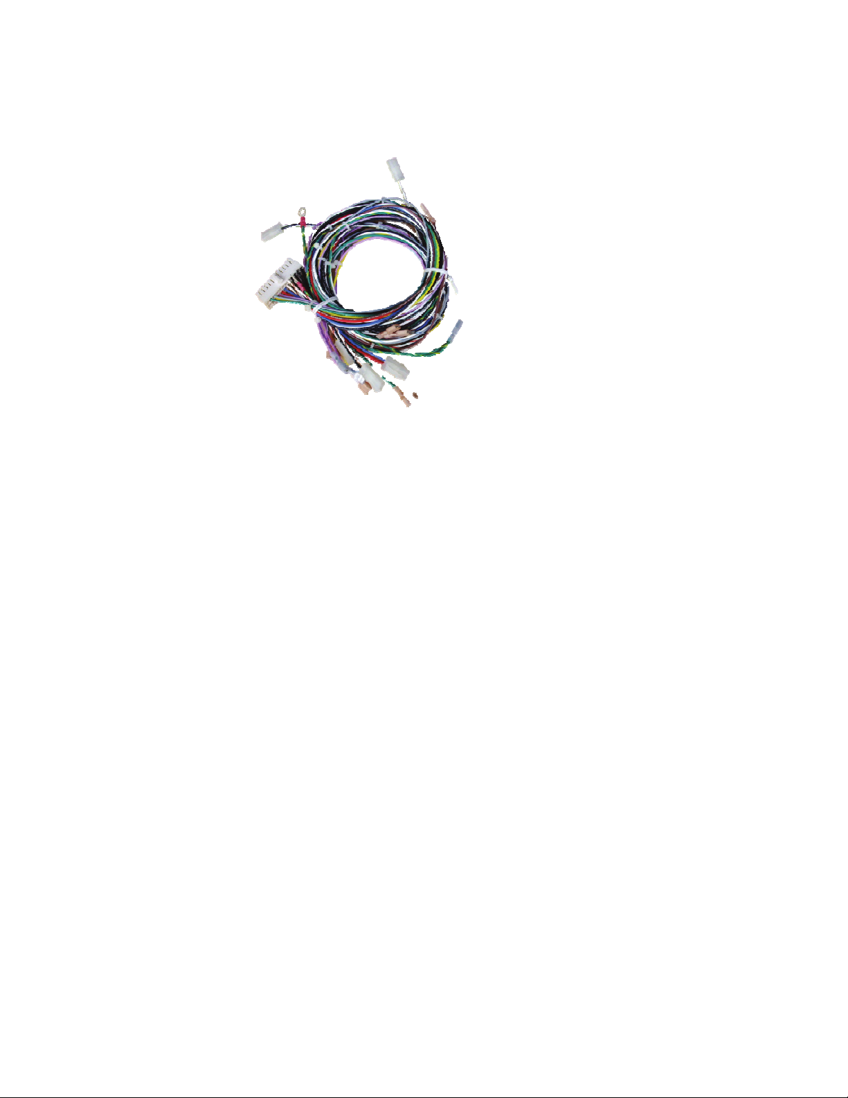
Wire Harness Assembly
Part #PP-1030-LR
For Models LR-01 (prior to 2011)
green wire to top terminal other end of green wire screwed to base
of unit
F:\AESBusinessSystems\AES Technical\Piece part instructions\PP-1030-LR Wire Harness Assembly LR01.doc
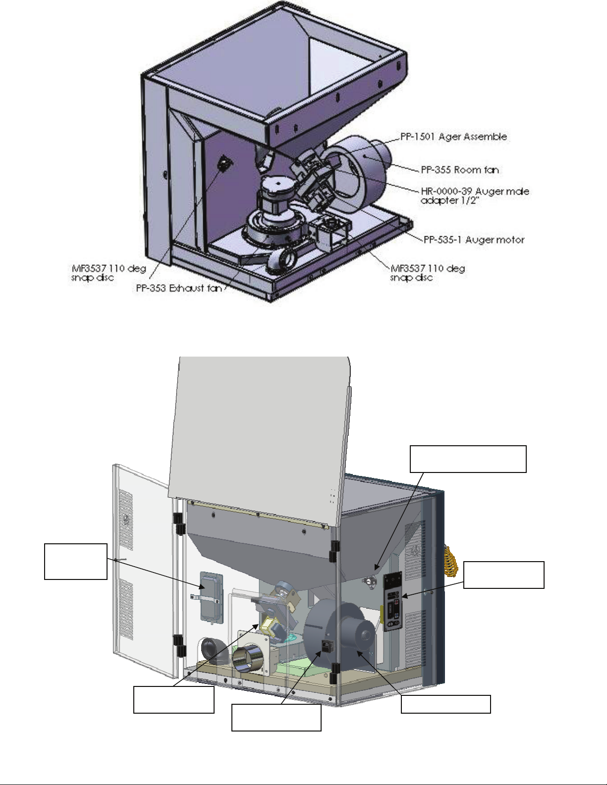
vacuum
switch
high limit snap disc
control board
auger motor
power inlet
F:\AESBusinessSystems\AES Technical\Piece part instructions\PP-1030-LR Wire Harness Assembly LR01.doc
 Loading...