

American Energy Systems O2 Catalytic User Manual
INSTALLATION OPERATION
& MAINTENANCE MANUAL
FOR
FREESTANDING MODELS: BBF, B, R
INSERT MODELS: BBF, B, O2
RETAIN THESE INSTRUCTIONS
Version 7.2

WARNING: COUNTRY FLAME RECOMMENDS A CERTIFIED PROFESSIONAL INSTALL AND
SERVICE WOOD BURNING STOVES. IMPROPER INSTALLATION OR SERVICE WILL
VOID THE COUNTRY FLAME WARRANTY. IMPROPER INSTALLATION CAN ALSO
RESTRICT, LIMIT, OR VOID A HOMEOWNER’S INSURANCE POLICY. READ THIS
ENTIRE MANUAL BEFORE UNDERTAKING THE INSTALLATION PROCESS. IMPROPER
INSTALLATION IS THE LEADING CAUSE OF WOOD STOVE PROPERTY DAMAGE. A
HOUSE FIRE, BODILY INJURY OR EVEN DEATH CAN OCCUR DUE TO IMPROPER
STOVE INSTALLATION. CHECK WITH LOCAL BUILDING OR FIRE INSPECTORS
ABOUT LOCAL CODE RESTRICTIONS AFFECTING INSTALLATION.
1 Country Flame Technologies grants no warranty, implied or written, for the installation or maintenance of any catalytic stove.
As such, Country Flame assumes no responsibility for any consequential damage resulting from the improper installation or improper
care of any specific catalytic stove.
2 Please fill out and return the warranty card within 30 days of purchase of a specific model catalytic stove.
3 ALWAYS consult local building authorities to determine if a permit is required for installation of any stove covered by this
manual.
4 ALWAYS consult local codes before installation to obtain information on local restrictions or additional local code
requirements.
5 ALWAYS maintain minimum clearances from all combustible surfaces and materials including clothing, drapes, furniture,
carpets, walls, wood, paper, etc. Do not store firewood within clearances established for a catalytic stove.
6 This stove requires a non-combustible fireplace hearth. Refer to the floor protection section in this manual.
7 ALWAYS connect any stove covered in this manual to a (a) listed UL103 or USC S629 rated type HT (2100
(b) code-approved masonry chimney with an appropriate flue liner. The chimney size should not be less than the stove flue collar size
or more than three times greater than the cross-sectional area of the flue collar.
8 NEVER OVER FIRE ANY FIREPLACE. If any part of a catalytic stove or chimney glows red it has been over fired.
Over firing causes a catalytic stove to operate at temperatures outside its designed capability. Over firing immediately voids the
catalytic stove warranty.
9 NEVER attempt to repair any part of a catalytic stove. Only qualified service personnel should make installations and
repairs. Any parts removed for servicing must be replaced prior to operation.
10 NEVER leave a catalytic stove unattended and burning on high. Uncontrolled and unattended high burn fires will lead to
over firing.
11 NEVER connect a stove described in this manual to a chimney flue already connected to another appliance.
12 NEVER install any Country Flame catalytic stove in a sleeping room.
13 NEVER CONNECT ANY PART TO AN EXISTING HOME AIR DUCT DISTRIBUTION SYSTEM.
14 NEVER use gasoline, lantern fuel, kerosene, charcoal lighter fluid, or similar combustible liquids to start or freshen up a fire.
Vapors from these liquids are highly explosive. Keep them a safe distance from stove.
15 ALWAYS use only solid wood fuel. Country Flame catalytic stoves have been approved for burning only dry seasoned
natural wood.
16 NEVER BURN GARBAGE, FLAMMABLE FLUIDS, OR TREATED WOOD.
17 NEVER allow creosote to build up in the chimney system. Inspect the chimney system at least twice monthly during use and
clean as required. Using green or improperly seasoned wood can greatly increase the production of creosote. Use wood with less than
25% moisture content in order to minimize creosote buildup.
18 ALWAYS wait until the unit is completely cool to perform any maintenance or cleaning procedures.
19 THIS STOVE IS HOT WHILE IN OPERATION. KEEP CHILDREN, CLOTHING, AND FURNITURE AWAY.
CONTACT MAY CAUSE SKIN BURNS.
20 SUPERVISE children when they are in the same room with an operating fireplace.
21 ALWAYS follow the lighting instructions in this manual; short cuts of any kind can be dangerous.
22 ALWAYS check local building codes and consult with your insurance company before installing your unit.
23 ALWAYS dispose of ash accumulations from your unit, using a metal container with a tight fitting lid. Place the closed ash
container on a non-combustible surface well away from all combustible materials, pending final disposal. Retain all ashes in the
closed container until they have thoroughly cooled.
24 INSTALL any safety screen; guard, or doors removed for maintenance prior to operation.
25
26 INSTALL a smoke detector within the proximity of a catalytic stove.
27 ALWAYS observe the unit closely during operation. If any part of the catalytic stove starts to glow red or white, it is in an
over fire condition. Close the air controls completely until the glowing material has returned to a normal dark color.
NEVER block free airflow through open vents connected to the fireplace units.
2
o
F) chimney or
28 NEVER burn wet or green wood. Firewood should be stored in a dry location away from the elements.
29 Check your chimney system carefully before installation. If in doubt about a chimney’s condition, contact a certified
professional.
30 ALWAYS comply with all minimum clearances to combustibles as they appear in this manual.
31 See the listing label located on the back of the catalytic stove for additional safety information.
32 ALWAYS start a fire with paper and kindling. Adding of wood fuel should be moderate as the fire progresses. Do not burn
large quantities of paper or foreign materials that create an extremely hot, quick fire that can lead to over fire conditions.
33 NEVER burn a catalytic stove with the damper open, except when reloading a stove.
34 ALWAYS build fires directly on the refractory brick floor. DO NOT use andirons or grates or elevate the fire in any other
manner.
35 For further information on using your catalytic wood stove, obtain a copy of the National Fire Protection Association’s
“Using Coal and Wood Stoves Safely”, NFPA No. NS-10-1978. The address of the NFPA is 470 Atlantic Avenue, Boston,
Massachusetts 02210.
36 INSTALLATION of a catalytic stove shall be in accordance with the Manufactured Home and Safety Standard (HUD), CFR
3280, Part 24.
37 Never allow the combustion or blower air intake to be blocked. Once a stove is installed as an insert do not allow a raised
hearth to create a blockage.
38 CAUTION: Do not turn a room air blower on until the fire has been burning for 30 minutes or longer. (This is not
applicable to units without the blower option.)
39 Never slam the door, strike the glass, or over tighten the glass screws.
40 ALWAYS operate a Country Flame catalytic stove with the door closed, except during refueling operation.
41 Do not burn coal in your stove
42 Keep the door of the unit closed except during the fueling process.
43 Check the door and glass seal frequently and keep them in good condition.
44 SAVE THESE INSTRUCTIONS
3
4
5

SAFETY NOTES...................................................................................................................................................................3
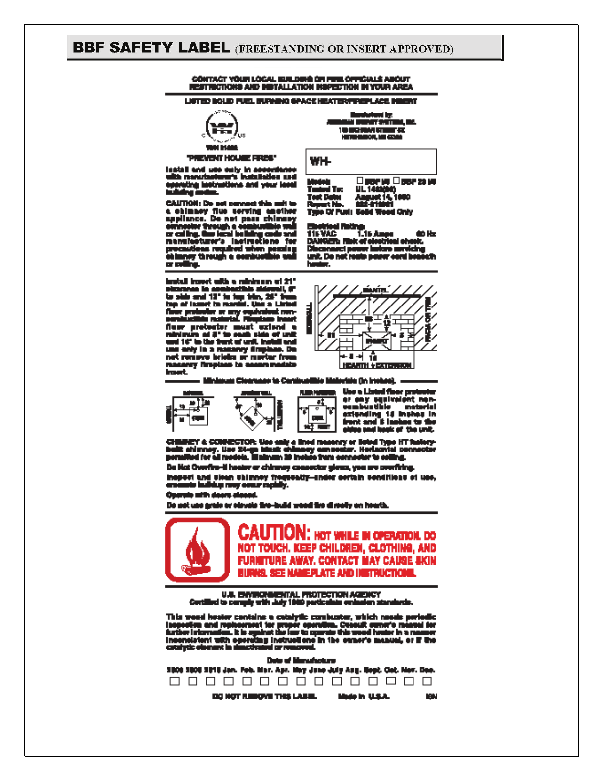
BBF SAFETY LABEL (FREESTANDING OR INSERT APPROVED).........................................................................5
B SAFETY LABEL (FREESTANDING OR INSERT APPROVED) .............................................................................6
R SAFETY LABEL (FREESTANDING APPROVED ONLY) .......................................................................................7
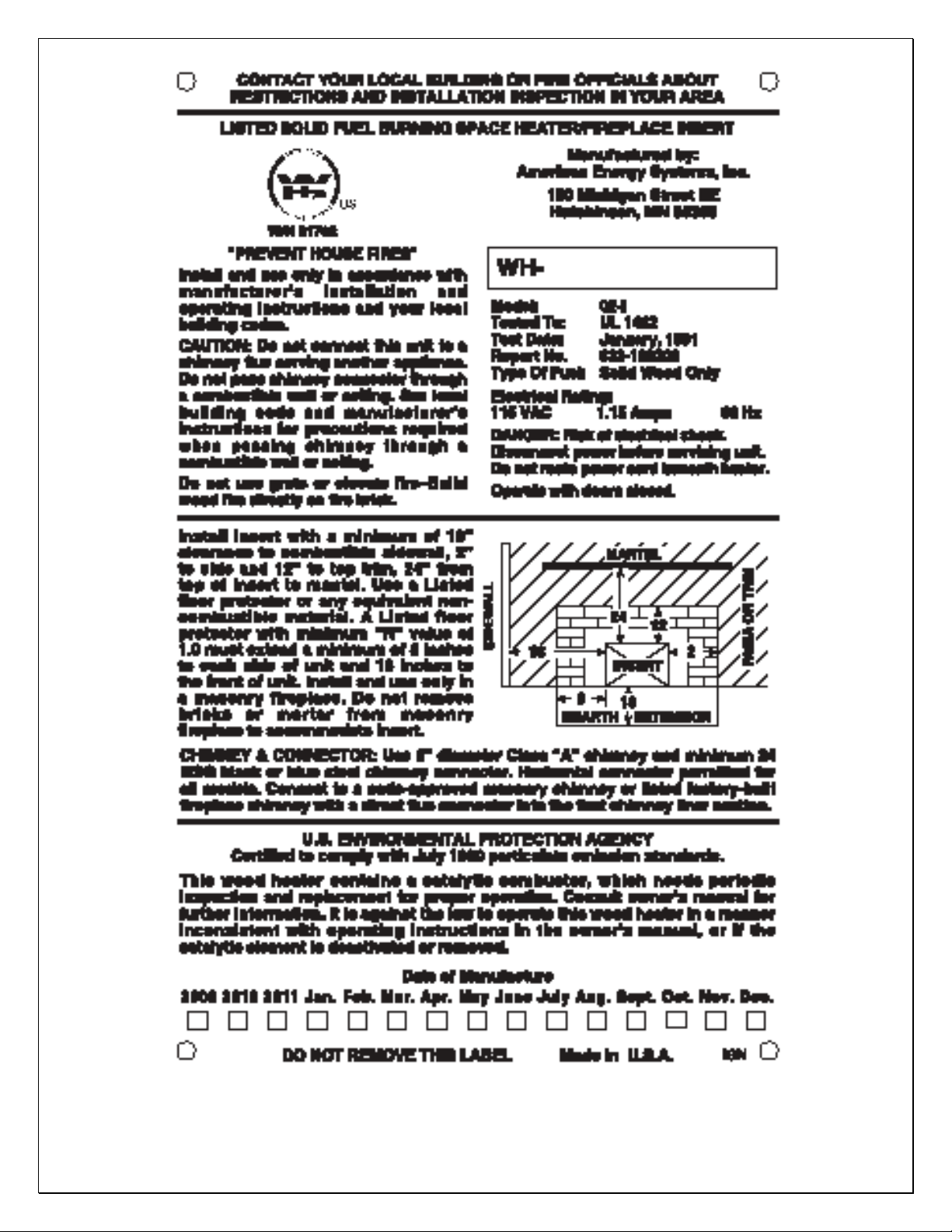
O2 SAFETY LABEL (INSERT APPROVED ONLY).......................................................................................................8
TABLE OF CONTENTS ......................................................................................................................................................9
EPA CERTIFIED......................................................................................................................................................13
LISTING/TESTING AGENCY................................................................................................................................13
MANUAL USAGE...................................................................................................................................................13
FORWARD – WHY A CATALYTIC STOVE?...............................................................................................................14
EARLY HISTORY...................................................................................................................................................14
HISTORICAL RESULTS ........................................................................................................................................14
THEORY OF OPERATION ..............................................................................................................................................15
LIMITED LIFETIME WARRANTY................................................................................................................................16
FREESTANDING INSTALLATION PROCEDURES ...................................................................................................18
MINIMUM CLEARANCES ...................................................................................................................................18
ALTERNATE MINIMUM CLEARANCES............................................................................................................19
ALCOVE CLEARANCES.......................................................................................................................................20
FLOOR PROTECTION REQUIREMENTS............................................................................................................21
CHIMNEY REQUIREMENTS ...............................................................................................................................22
FREESTANDING LEG REQUIREMENTS............................................................................................................23
STOVE INSTALLATION PREPARATION ..........................................................................................................24
INSERT INSTALLATION PROCEDURES ....................................................................................................................25
FACTORY BUILT FIREPLACES...........................................................................................................................25
MASONRY BUILT FIREPLACES ........................................................................................................................25
DRAFT .....................................................................................................................................................................26
MINIMUM CLEARANCES ...................................................................................................................................26
FLOOR PROTECTION REQUIREMENTS............................................................................................................26
SHROUD AND TRIM INSTALLATION................................................................................................................28
MOBILE HOME INSTALLATION..................................................................................................................................29
MOBILE HOME RULES.........................................................................................................................................29
MOBILE HOME CLEARANCES ..........................................................................................................................29
MOBILE HOME STOVE ATTACHMENT ...........................................................................................................30
MOBILE HOME FLOOR PROTECTION...............................................................................................................31
MOBILE HOME CHIMNEY AND DUCTS...........................................................................................................31
6

STOVE TERMINOLOGY .................................................................................................................................................34
STOVE COMPONENTS..........................................................................................................................................34
MANUAL DRAFT CONTROLS.............................................................................................................................34
CATALYTIC COMBUSTORS................................................................................................................................35
CATALYTIC BYPASS ROD...................................................................................................................................35
BLOWER UNITS.....................................................................................................................................................36
8” PROBE THERMOMETER..................................................................................................................................36
WOOD FUEL REQUIREMENTS ..........................................................................................................................36
CHIMNEY................................................................................................................................................................37
CHIMNEY CONNECTOR ......................................................................................................................................38
FLUE TRANSITION ...............................................................................................................................................38
WALL THIMBLE ...................................................................................................................................................38
MODEL BBF (FREESTANDING/INSERT) ....................................................................................................................39
MODEL BBF SPECIFICATIONS (FREESTANDING/INSERT) .................................................................................41
MODEL B (FREESTANDING/INSERT) .........................................................................................................................42
MODEL B SPECIFICATIONS (FREESTANDING/INSERT) ......................................................................................44
MODEL O2 (INSERT ONLY) ...........................................................................................................................................45
MODEL O2 SPECIFICATIONS (INSERT ONLY) ........................................................................................................47
MODEL R (FREESTANDING ONLY) ............................................................................................................................48
MODEL R SPECIFICATIONS (FREESTANDING ONLY)..........................................................................................50
APPENDIX A: REPLACEMENT PARTS DESCRIPTION...........................................................................................51
CATALYST PARTS ...............................................................................................................................................51
DOORS.....................................................................................................................................................................51
ELECTRICAL..........................................................................................................................................................51
REFRACTORY BRICK...........................................................................................................................................52
GLASS......................................................................................................................................................................52
HANDLES & KNOBS ............................................................................................................................................53
HARDWARE ..........................................................................................................................................................53
INSULATION .........................................................................................................................................................53
MISCELLANEOUS.................................................................................................................................................53
MOTORS..................................................................................................................................................................54
TRANSITIONS .......................................................................................................................................................54
OWNER'S MANUAL .............................................................................................................................................54
TRIM & GRILLS.....................................................................................................................................................54
GASKETS ...............................................................................................................................................................55
7

APPENDIX B: OPERATION & MAINTENANCE GUIDE...........................................................................................56
FIRST FIRE, STEP 1................................................................................................................................................56
FIRST FIRE, STEP 2................................................................................................................................................56
FIRST FIRE, STEP 3................................................................................................................................................56
FIRST FIRE, STEP 4................................................................................................................................................56
FIRST FIRE, IGNITION .........................................................................................................................................56
DRAFT PROBLEMS ...............................................................................................................................................57
FIRST LARGE FIRE................................................................................................................................................58
CARE OF STOVE GLASS: ....................................................................................................................................59
GLASS REPLACEMENT........................................................................................................................................59
GLASS-CERAMIC SPECIFICATIONS..................................................................................................................60
GLASS-CERAMIC CLEANING.............................................................................................................................60
DECORATIVE DOORS ..........................................................................................................................................61
ROOM AIR BLOWER MAINTENANCE...............................................................................................................61
ROOM AIR BLOWER TESTING ..........................................................................................................................62
BLOWER MALFUNCTION....................................................................................................................................62
NO ELECTRICITY..................................................................................................................................................62
CREOSOTE BUILDUP............................................................................................................................................63
FIREBOX TIPS AND TECHNIQUES.....................................................................................................................63
APPENDIX C: CATALYTIC SYSTEM ...........................................................................................................................64
THE CATALYTIC COMBUSTOR ..................................................................................................................................64
CATALYTIC COMBUSTOR CLEANING......................................................................................................................64
REPLACING THE COMBUSTOR...................................................................................................................................65
WARRANTY ....................................................................................................................................................................66
HOME INSURANCE........................................................................................................................................................66
FEDERAL LAW ...............................................................................................................................................................66
COMBUSTOR PROBLEMS ............................................................................................................................................66
MODEL B, BBF, AND R CATALYST INSPECTION & REPLACEMENT..................................................................67
CLEANING INSPECTION...............................................................................................................................................67
REPLACEMENT INSPECTION......................................................................................................................................67
REPLACEMENT ..............................................................................................................................................................67
MODEL O2 CATALYST INSPECTION & REPLACEMENT.......................................................................................68
CLEANING INSPECTION...............................................................................................................................................68
REPLACEMENT INSPECTION......................................................................................................................................68
REPLACEMENT ..............................................................................................................................................................68
APPENDIX D: BLOWER SYSTEMS, ELECTRICAL ..................................................................................................69
BLOWER THEORY OF OPERATION ...........................................................................................................................69
MODEL BBF, B ...............................................................................................................................................................69
MODEL O2 .......................................................................................................................................................................70
MODEL R..........................................................................................................................................................................71
APPENDIX E: WARNING LABELS................................................................................................................................72
APPENDIX F: TROUBLESHOOTING GUIDE..............................................................................................................75
8
APPENDIX G: CHIMNEY & VENTING GUIDE ..........................................................................................................77
VENTING SYSTEMS.......................................................................................................................................................77
THIMBLE INSTALLATION............................................................................................................................................78
OUTSIDE AIR COMBUSTION ......................................................................................................................................81
CHIMNEY INSTALLATION...........................................................................................................................................81
PREFABRICATED CHIMNEY SYSTEM INSTALLATION ........................................................................................84
EPA CERTIFIED
All Country Flame catalytic stoves have passed rigorous emission standard testing. All Country Flame catalytic stoves
have been certified by the United States Environmental Protection Agency.
LISTING/TESTING AGENCY
All Country Flame catalytic stoves have been tested to UL listing standards UL1482, ULC-S627 for installation into
residential dwellings, including standard construction units, mobile home, or modular home units. All catalytic stoves
tested to UL standards by Intertek Testing Services, NA, Inc., 8431
MANUAL USAGE
Please read, understand, and carefully follow all instructions, installation procedures, and proper care and maintenance
advice found in this manual. Please observe the safety instruction contained in this manual. If there are any questions,
please contact Country Flame or one of its authorized dealers.
9
Why consider a Country Flame Technologies catalytic stove for your home?
EARLY HISTORY
During the 1970’s Americans became obsessed with both indoor and outdoor air quality. By the early 1980’s America’s
obsession turned into governmental regulatory controls as the screams for improved air quality reached fever pitch.
Someone coined the phrase “fugitive emissions” and government agencies sprang into action to define, document, and
control fugitive emissions being released into the atmosphere from just about any source imaginable.
Of course, government involvement meant that dozens of laboratories sprang into action to begin the study of fugitive
emissions. Soon government laboratories had full-fledged programs studying the wood burning fireplace and stove
industry. The objective: to define the atmospheric (fugitive) emissions that was resulting from the use of every fireplace
or stove. At this historic point in time, the fireplace manufacturing industry changed from “art form to science” and
spelled the doom of literally thousands of small “mom and pop” manufacturers.
The fireplace industry had long understood the correlation between the three parts of a fire: a) fuel, b) oxygen, and c) heat
but the exacting theory of mixing these basic items and the resultants (emissions) eluded even the most sophisticated pre1970 fireplace manufacturer. Not the government laboratories! Quantification (defining numbers) was a government
specialty and thousands of papers were written on non-airtight and airtight fireplace combustion. These learned papers
defined and quantified every aspect of wood burning particulate emissions.
HISTORICAL RESULTS
The laboratory findings were conclusive. In 1970, wood stoves did emit large amounts of what has come to be known as
polycyclic organic matter, or POM’s. Many of these POM emissions were known to be carcinogens (meaning cancer
causing.) Armed with new documented science and an overabundance of evidence caused the Regulator Agencies to
spring into action. Soon draft government (federal and state) regulations were proposed that would establish limits on the
emissions of just about every fuel-burning device, including wood burning products. Once these government regulations
were rumored to be just a vote away, fireplace manufacturers sprang into action to design product that would meet the
new evolving emissions criteria.
Country Flame Technologies was part of that late 1970’s push to produce cleaner burning fireplace and stoves. Like all
fireplace manufacturers, Country Flame asked the question, HOW CAN EMISSIONS BE CONTROLLED? The answer
was as simple as the question, ENSURE FIREPLACES BURN 100% EFFICIENT. 100% BURN EFFICIENCY
ENSURES ALL UNACCEPTABLE EMISSIONS ARE ELIMINATED. It is always easier to state the problem and an
answer than it is to put it into practice. Country Flame engineers remained undaunted. In the early 1980’s Country Flame
Technologies began work on a full line of catalytic wood burning freestanding or insert stoves. Country Flame’s catalytic
stoves have evolved into an efficient and clean wood-burning product line.
Most likely, if you have read this far, you are strongly thinking about or have purchased a Country Flame catalytic stove.
After almost three decades of continuously developing this line of products, all of us at Country Flame are very proud of
this American born, American tested, and American produced product. With a sense of pride and dedication, our
employees wish you and your family a lifetime of happiness and warmth with a Country Flame catalytic stove. On behalf
of Country Flame, THANK YOU.
10

The purchase of a Country Flame Technologies catalytic stove is usually made based on its looks, its heating capacity, and
because of reduced emissions (clean and efficient burn.) Once the catalytic unit has been properly installed in a home,
usually the next question asked by the homeowner is how can a catalytic stove’s favorable operational characteristics be
maintained over the life of the product?
In 2004, the study of woodstove emissions and woodstove efficiency remains a strongly debated issue. “Experts” use
significantly different methodologies to arrive at often-conflicting conclusions. One thing is for certain, these same
experts unanimously agree on one aspect of a stove’s pollution and creosote production process: All stove studies
conclude that a homeowner’s operating procedure dramatically impacts the production of POM’s (fugitive emission) more
than any other single factor that has been examined over the past 20 years! BOTTOM LINE: a homeowner must
understand and operate a catalytic stove correctly to maintain its cleanliness and efficiency!
Catalytic stove theory is quite simple. The catalytic combustor begins oxidizing carbon monoxide and other flue gases
around 600
chimney unrestricted. As the stove reaches 700
O
F. With the bypass flue open, the stove operates as a non-catalytic stove and fugitive emissions escape up the
O
F degrees, close the bypass flue. All emissions are then forced to travel
through the combustor on their way to the chimney. As the stove’s temperature continues to rise, the combustor ignites
more particulates effectively burning these emissions. This secondary combustion, as it is called, occurs traditionally at
O
temperatures 300
F to 600 OF degrees lower than in non-catalytic stoves. Once “light-off” of the catalytic combustor
occurs, the overall efficiency and cleanliness of burn is dramatically improved in a catalytic stove.
The catalytic combustor creates a secondary burn process that “scrubs” the exhaust emissions producing a cleaner exhaust
gas. When operated properly, the Country Flame catalytic stove benefits are a) improved efficiency, b) longer burn times,
c) reduced chimney fire potential, and d) reduced operating costs. In order to maintain the Country Flame warranty, the
catalytic combustor must be properly engaged at all times during operation. Removing the combustor is dangerous and
can lead to uncontrolled or over firing. Operation of the stove with the combustor removed instantly voids Country
Flame’s warranty. Further, operating a woodstove in any manner that is restricted by Country Flame can cause a
homeowner’s insurance policy to be negatively affected. REMEMBER: Federal Law requires all catalytic woodstoves
to be maintained and operated with combustors in place over the life of the stove.
The catalytic combustor is a honeycomb ceramic and noble metal device. The catalytic combustor initiates combustion of
secondary gases at lower temperatures than would be possible without the combustor installed while not destroying itself.
Most modern catalytic combustors are designed to survive over 12,000 hours of continuous use. Operator use, firing
practices, and the type of fuel used can all negatively affect the life expectancy of the combustor. Signs of combustor
problems include increased smoke from the chimney, creosote accumulation, poor performance of the unit, continued
firebox smoking, and an increase in fuel consumption. Here are five ways to produce cleaner air when operating a
catalytic woodstove:
1 Use the largest diameter log that is practical in a particular model.
2 Build as small a fire as practical.
3 Keep the firebox hot and attempt to maintain a constant stove temperature.
4 Do not dramatically change draft settings. Gradual draft changes improve performance.
5 Avoid excessively dry or wet fuel. 20 to 25% moisture content in wood is good.
NEVER FORGET: Correct operation of a catalytic woodstove is key to its efficiency and life expectancy!
11

AMERICAN ENERGY SYSTEMS INC. LIMITED PRODUCT WARRANTY
This warranty is in effect on all products sold after 01/01/2009 and supersedes any and all warranties currently in existence.
Please keep a copy of this warranty for your personal records or in the event of a claim
American Energy Systems Inc., hereinafter referred to as (AES), warrants to you, the original consumer purchaser, that this product is
free from defects in material and workmanship for a period of five (5) years from the original purchase date minus any time past one
(1) year from manufacturing date, and that the product’s electrical parts and steel firepot, are free from defects in material and
workmanship for a period of one (1) year from the original consumer purchase date minus any time past one (1) year from
manufacturing date, and that the cast iron firepot models carry a lifetime warranty against defect in material or workmanship
(excluding war page or deterioration), and that door glass carries a lifetime replacement warranty against heat breakage (does not
cover accidental breakage) . There is expressly no warranty on installation of product, any venting, grates, gaskets, door latches,
insulation, ceramic or brick boards/logs/backing, paint, plated surfaces/doors/trims, baffles, bushings, bearings, auger flightings, war
page or discoloration of steel or plated parts or any other normal wearing part. In the event the product fails to conform to this
warranty, AES, through the place where you purchased the product or if purchased on the AES E-Com store directly through AES,
will provide the parts and components necessary to remedy such nonconformity. AES will not be responsible for any labor, mileage
or freight cost to the factory under this warranty. This warranty is not transferable.
In order to obtain performance under this warranty, you must (1) have registered this warranty within 30 days of purchase by
completing and returning the warranty registration card or filling in the on-line warranty registration form at www.magnumheat.com,
and (2) promptly report the claimed nonconformity to your place of purchase, also providing your name, address, phone number,
proof of purchase, date of purchase, the model and serial number of the stove, digital pictures of installation and venting inside and
outside of the home, pictures of the claimed nonconformity part and the claimed nonconformity. All claims must be submitted in
writing to your place of purchase.
AES shall have no warranty obligations if this product; (1) was not purchased from an authorized AES dealer; (2) was not installed by
a AES dealer or other qualified installer; does not have outside combustion air hooked directly to the unit; (3) was not operated and
maintained in strict accordance with the manufacturer’s instructions, local or national codes or (4) was subject to abuse, misuse,
negligence or accident. AES shall have no warranty obligation for damage caused by improper handling, freight damage (must be
reported to freight provider), over-firing, unapproved fuel, variance in feed rates, variances in BTU output or the unauthorized
disassembly or modification of the product. AES shall have no warranty obligation if this warranty is not timely registered, for claims
which are not submitted through the selling AES dealer, or for claims submitted verbally or without the required information and
documentation.
Before exercising this warranty, an AES representative (the place where the product was purchased or AES approved person) must
inspect the part/unit to determine if the part/unit is defective. If a local AES representative is not available the original purchaser of
the product must submit digital pictures of the part/unit, installation of the unit to AES at technical@magnumheat.com
inspection reveals that the failure is due to defective material or workmanship and the part is covered by the conditions of this
warranty, AES will, at its option, repair the defective part/unit. The sole duty of AES and liability under this warranty is limited to the
repair of the covered defective part/unit. The purchaser shall assume all costs related to shipping the replacement parts or return of the
unit to the factory for repairs. If it is determined that the defect was caused by AES, AES will cover the costs of shipping the repaired
part/unit to an AES approved shipping point. AES will not cover additional freight or delivery services such as residence delivery
charges, special handling, etc.
INSTALLATION, VENTING, REMOVAL OR REINSTALLATION COSTS ARE NOT COVERED BY THIS WARRANTY.
THE WARRANTY PRINTED ABOVE IS THE ONLY WARRANTY APPLICABLE TO THE PRODUCT. ALL
OTHER WARRANTIES, EXPRESSED OR IMPLIED, INCLUDING, WITHOUT LIMITATION, THE IMPLIED
WARRANTIES OF MERCHANTABILITY AND FITNESS FOR A PARTICULAR PURPOSE, ARE DISCLAIMED.
IT IS UNDERSTOOD AND AGREED THAT AES’S LIABILITY UNDER THIS WARRANTY SHALL BE LIMITED
TO THE PROVISION OF REPLACEMENT PARTS AND SHALL NOT INCLUDE LIABILITY FOR SPECIAL,
INCIDENTAL OR CONSEQUENTIAL DAMAGES. ANY ACTION BROUGHT UNDER THIS WARRANTY MUST
BE BROUGHT WITHIN ONE YEAR OF THE ACCRUAL OF THE CAUSE OF ACTION AND MAY ONLY BE
BROUGHT IN THE CIRCUIT COURT OF MCCLOUD COUNTY, MINNESOTA.
Some states do not allow limitations on how long an implied warranty lasts or the exclusion or limitation of incidental or consequential damage, so
the above limitations may not apply to you. This warranty gives you specific legal rights, and you may also have other rights which vary from state
to state.
ALL WARRANTY CLAIMS MUST BE SUBMITTED IN WRITING THROUGH THE PLACE WHERE THE PRODUCT WAS
PURCHASED. In the event where the place of purchase has ceased business or if you feel that there is a legitimate reason that you
If the
12

cannot submit your claim to the place where the product was purchased you may make a written request to the factory by emailing
your request along with all of the required information to technical@magnumheat.com
recognized. If it is determined that warranty could have been performed by the place of purchase, the factory will deny the
claim.
Included with the claim must be the following information: (if this information is not complete, the claim will be denied)
Name, address, telephone number, email address, of place of business where product was purchased & also purchaser contact
info.
Date of purchase, model and serial number of product, digital pictures of product (front, sides, back, venting inside and
outside)
(If there is ductwork, there must be digital pictures of entire ductwork installation, static pressures, air flow measurements,
and contact information of licensed/factory certified contractor that installed unit)
Nature of defect, what has been serviced (service record), who installed product along with contact information.
. NOTE: Verbal requests will not be
13

American Energy Systems, Inc
150 Michigan Street SE
Hutchinson, MN 55350
- - - - - - - - - - - - - - - - - - - - - - - - - - - - - - - - - - - - - - - - - - - - - - - - - - - - - - - - - - - - - - - - -
WARRANTY INFORMATION
Name ___________________________________________________________
Address ________________________________ City ____________________
State: __________ Zip _____________ Phone Number _____________
Authorized Dealer __________________________________________________
Dealer Telephone #: __________________________________________________
Date Purchased: __________________________________________________
Model No# ___________________ Serial No# __________________
Installed By: __________________________________________________
Trained By: __________________________________________________
NOTE: FILL OUT THE ABOVE WARRANTY INFORMATION AND KEEP THIS
COPY FOR YOUR PERSONAL RECORDS. REGISTRATION OF THIS
WARRANTY CONSTITUTES YOUR ACCEPTANCE OF ALL TERMS
CONTAINED THEREIN.
14
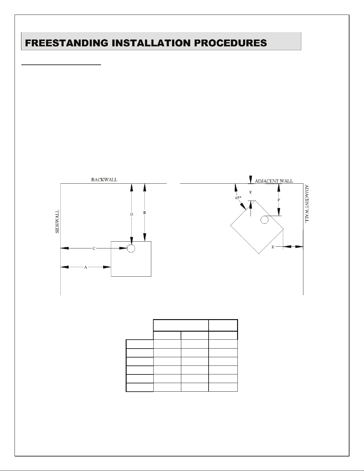
MINIMUM CLEARANCES
1. FIGURE 1 shows how to measure freestanding clearances for Country Flame catalytic models covered by this
manual. Table 1 provides minimum clearances for specific models that must be maintained in FIGURE 1. The
installer should familiarize themselves with FIGURE 1 and TABLE 1, understand MINIMUM CLEARANCE
requirements, incorporate, and maintain these clearances during installation.
Official wall clearances to combustibles are located on each Safety Testing Label that is located on the
back of each Country Flame catalytic stove. REMEMBER that all minimum clearances must be
measured and maintained from that part of the stove that is nearest to the combustible material. If there
is any doubt or confusion about clearance requirements, refer to both national and local codes. Failure
to properly install a stove and maintain proper clearances voids the warranty and can lead to a house
fire.
FIGURE 1: MINIMUM FREESTANDING CLEARANCE DIAGRAMS
Chimney
Pipe
Model
A 21 18 12
B 20 20 3
C 18 29 N/A
D 20 21 N/A
E 20 20 5
F 18 24 N/A
Single* Single* Double*
BBF B R
*S – Single wall chimney pipe
*D – Double wall chimney pipe
TABLE 1: MINIMUM CLEARANCES,
IN INCHES, REFER TO FIGURE 1
2. Contact the local building code department in your area to obtain necessary information about the installation of
15
the particular stove being installed in your home.
3. Questions to ask the local code department include but are not limited to:
a. Are there any local codes that impact installation and how do they differ from national codes?
b. What are the applicable local codes and any differences that will guide the installation of a stove covered
in this manual?
c. Country Flame stoves are approved for mobile home installation. What are the local codes governing
mobile home installation?
d. What electrical code must the stove power outlet meet? Country Flame’s woodstove requires a grounded
three-prong electrical outlet rated at 120VAC, 60Hz, and 15A.
e. What, if any, local code amendments are there concerning woodstove installation?
f. Does a permit need to be obtained before the stove is installed?
g. What is the cost of a permit, if it is required?
h. What is the local code concerning rooms where a woodstove cannot be installed?
i. Are smoke detectors required by local code? How many and where are they to be located? Country
Flame strongly recommends the use of smoke and carbon monoxide detectors in the home.
ALTERNATE MINIMUM CLEARANCES
1. Alternate minimum clearances can be obtained by following what is known as the 12 RULE.
2. Essentially, the 12 RULE states that no clearance can ever be less than twelve inches (12” or 300mm) from a
catalytic stove to any COMBUSTIBLE WALL regardless of the additional type of protection provided for a specific
combustible wall. Refer to FIGURE 2 for 12 RULE examples.
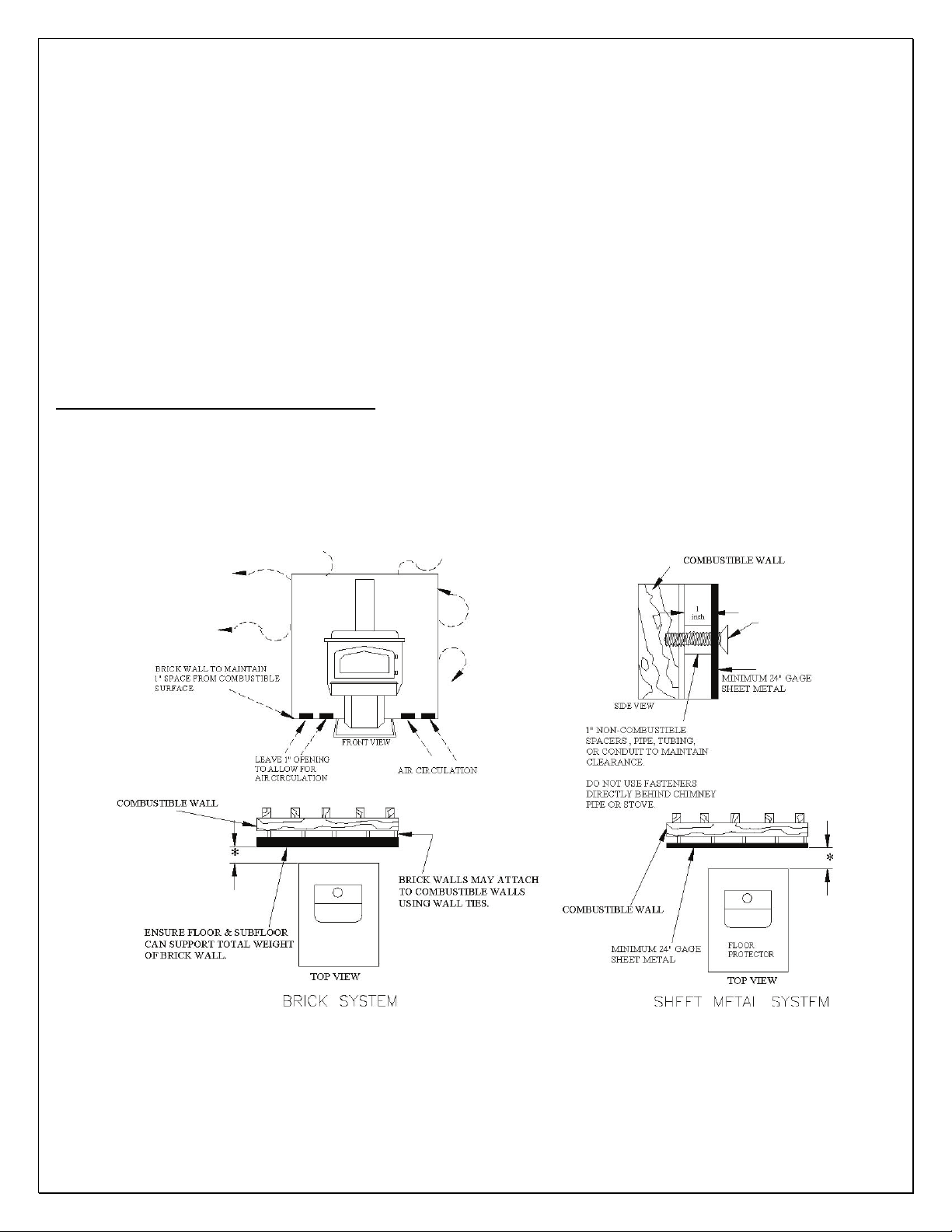
FIGURE 2: *12 RULE CLEARANCE SYSTEMS
3. If the 12 RULE is used, additional wall protection must be provided to protect combustible walls from radiated
heat.
4. Clearance reductions apply only to the clearances found in TABLE 1 of this manual for single wall stovepipe.
16
Reduced clearances CANNOT be applied to the already reduced clearances of a double wall insulated pipe with an added
heat shield.
EXAMPLE: The rear clearance defined for a Model B (FIGURE 1 and TABLE) measurement B, is listed as twenty
inches (20”, 500mm.) This rear clearance, for a Model B may be reduced up to 66% but never less than twelve inches
(12”, 300mm) by using either of the wall protection procedures listed in ITEM 5 and ITEM 6.
5. Tested and Listed Wall Protectors: Clearances to combustibles may be reduced if a tested and listed wall
protector is installed over a combustible surface when the following conditions exist:
a. A dead air space of 1” must separate the tested and listed wall protector from the combustible wall
surface.
b. The tested and listed wall protector must extend from floor to ceiling with a full 1” clearance for air
circulation. This air circulation must be between the combustible walls and the tested and listed wall protector all the way
from the floor to the ceiling.
c. Spacers (preferably 1”ceramic rather than metal) must be located at the corners on the tested and listed
wall protector rather than behind the heater or the chimney connector.
6. Untested and Unlisted Wall Protectors: Untested and Unlisted Wall Protectors may be constructed of masonry,
24-gauge metal or thicker sheet metal, or non-combustible half-inch (0.5”, 12.5mm) thick insulation board. If
untested and unlisted protectors are used, then Item 5a, 5b, and 5c above must be modified to read one and a half
inches (1.5”, 37.5mm) instead of the 1” separation.
NOTE: If the installer plans to use a reduced clearance by using double wall chimney connectors as shown in
TABLE 1, then the stove clearances may not be further reduced by utilizing any of the methods listed in ITEM 5
or ITEM 6.
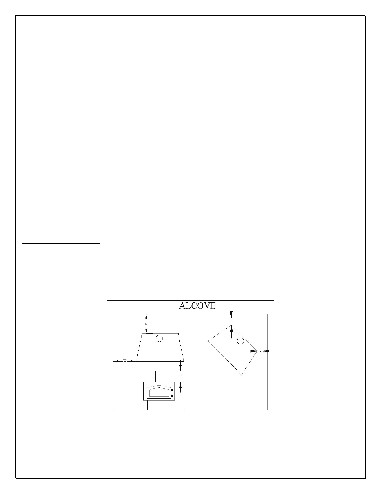
ALCOVE CLEARANCES
1 Country Flame’s Model R is the only catalytic stove tested and approved for alcove installation. The Model R
must use UL 103 listed double wall chimney pipe for all alcove installations.
2 Alcove clearances require the use of listed UL 103 or listed ULC S629 Type HT (2100
pipe to establish clearances according to FIGURE 3 as listed in TABLE 3.
O
F) double wall chimney
FIGURE 3: ALCOVE CLEARANCES
17
MODEL
R
A B C D
3 12 5 42
TABLE 2: ALCOVE CLEARANCES, IN INCHES, REFER TO FIGURE 3
3 If a Model R is to be installed in an Alcove, contact a local building professional or building inspector to
obtain information on any local code requirements for such installation.
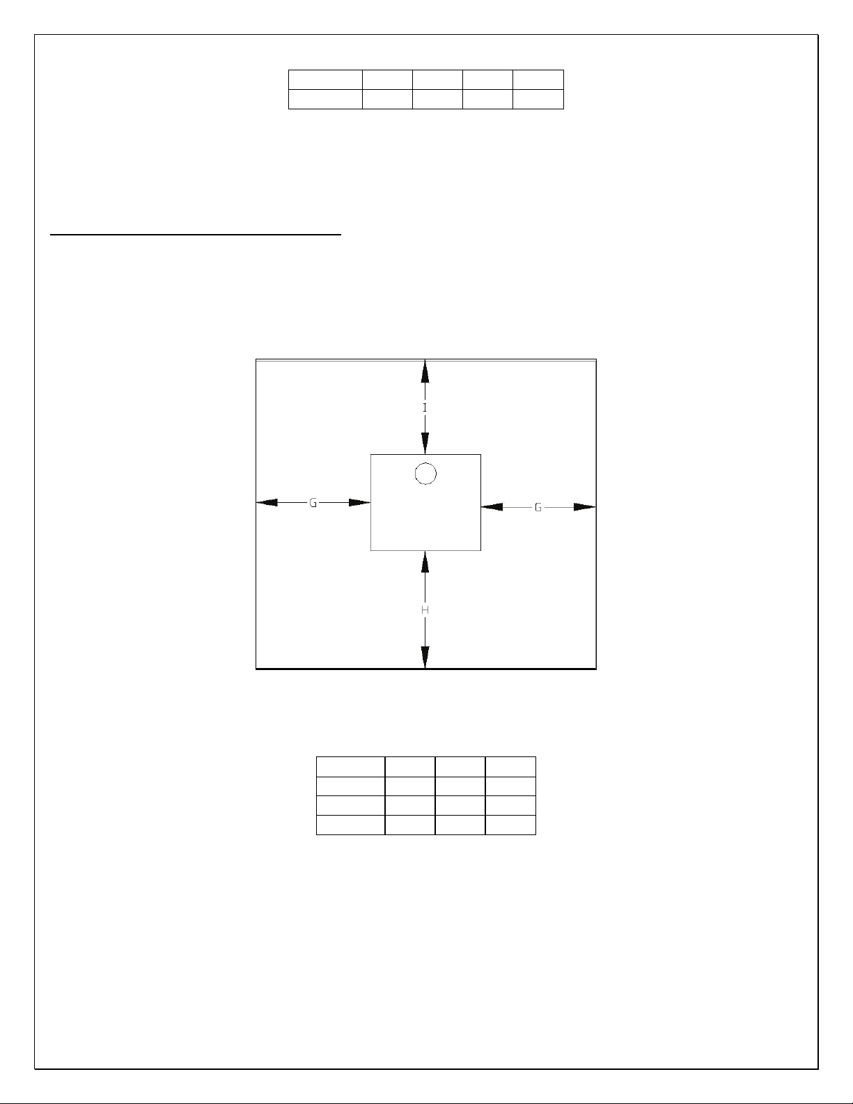
FLOOR PROTECTION REQUIREMENTS
1. All Country Flame freestanding catalytic woodstoves require a listed floor protector that is noncombustible.
Country Flame catalytic stoves were tested with a listed floor protection that had a thermal conductivity of K =
0.85 BTU-inch per hour per square foot per degree Fahrenheit and that was 3/8” thick (9.5mm) non-asbestos
millboard. Refer to FIGURE 4 and TABLE 4 for floor protector information.
FIGURE 4: FLOOR PROTECTOR DIMENSIONS
NOTE: Chimney connectors must have 2 inches of floor protection from all sides in all direction.
MODEL
G
H
I
BBF B R
8 8 8
18 18 16
8 8 3
TABLE 3: FLOOR PROTECTOR, IN INCHES, REFERS TO FIGURE 4
2. If a floor protector, different from the tested floor protector, is to be used, it must meet or exceed the requirements of
the listed R-value of the tested floor protector. To convert alternate floor protectors to their respective R value use the
following procedures:
a. Convert floor material specification to R-value.
i. R-value is given – no conversion is required.
ii. k-factor is given with required thickness (T) in inches: R = (1/k) x T.
iii. C-factor given: R = 1/C.
18

b. Determine the R-value of the proposed alternate floor protector.
i. Use the formulas provided in STEP 2 to convert values not expressed as “R.”
ii. For multiple layers of material, add each R-value of each layer to determine the materials overall RValue.
c. If the overall R-value of the alternate material is greater than the tested material defined in STEP 1, then the
alternate floor protection is acceptable.
d. EXAMPLE:
i. The tested material was 3/8 inch thick with a k-factor of 0.85.
ii. The R-value of the tested material was R = (1/0.85) x 3/8 = 0.44.
iii. Suppose the tested material is to be replaced by 4-inch brick material with a C of 1.25.
iv. The R-value of the alternate brick material is R = (1/1.25) = 0.80. Since the R-value of the alternate brick
material [R = 0.80] is greater than the tested material’s R-value [R = 0.44] then the alternate material is acceptable for use
in the specific application.
3. Listed Floor Protector Definitions:
a. Thermal Conductance = C = Btu/(hr)(ft
b. Thermal Conductivity = k = (Btu)(inch)/(hr)(ft
c. Thermal Resistance = R = (ft
2
)(hr)(OF)/Btu = (m2)(OK)/W
2)(O
F) = W/(m2)(OK)
2)(O
F) = W/(m)(OK) = Btu/(hr)(ft)(OF)
d. HEARTH EXTENSIONS must total an R-value equivalent to or greater than 2.0 to ensure proper floor
protection for combustible materials.
4. WARNING: A catalytic stove must always be placed on a listed floor protector if the existing floor where the stove
is to be placed is made of any combustible material. IF THE AREA WHERE THE STOVE IS TO BE PLACED IS
CARPETED, THE CARPET MUST BE REMOVED. A LISTED FLOOR PROTECTOR IS NEVER TO BE
PLACED ON CARPET. CHECK LOCAL CODES FOR ADDITIONAL CARPET RESTRICTIONS AND FLOOR
PROTECTION REQUIREMENTS.
CHIMNEY REQUIREMENTS
The installer must be prepared to deal with one of two different types of chimneys that will be encountered during the
installation of a freestanding catalytic stove. The chimney systems are defined as follows:
1 FACTORY BUILT CHIMNEY: Stainless steel pipe with interlocking sections that can be double walled or
triple wall air-cooled or double wall-insulated stovepipe. In the event that a factory built chimney already exists, a
certified chimney professional should inspect the chimney system for mechanical or structural weakness, broken, leaky,
corroded or warped joints or any other signs that would indicate the need for replacement. All sections of chimney that
pass through the floors, ceilings, or attics should be inspected for proper installation, adherence to code, and correct
installation to protect from overheating.
2 MASONRY BUILT CHIMNEY: Masonry chimneys are built with several different types of brick material.
The outer brick is for appearance and the inner brick (called tile) are designed to withstand high temperature exhaust gases
being emitted from the fire. A good masonry chimney system should not have cracks, loose mortar, missing sections of
tile, other signs of deterioration or blockage of the flue. A qualified mason should perform construction or repairs to a
masonry chimney. Inspection of a chimney should be completed by a certified chimney sweep and before a new stove is
attached, the chimney sweep should certify the chimney has no obstruction and is clean of creosote and debris.
3 OVERSIZED CHIMNEY: Regardless of the type of chimney used, over sizing a chimney will result in reduced
performance of the catalytic stove. A chimney’s flue size should be no more than three (3) times the cross sectional area
of the flue size of the catalytic stove’s flue collar. EXAMPLE: Assume the stove’s flue collar has an inside diameter of 6”.
This means the stove’s flue area is approximately 28 square inches, which means the chimney’s cross sectional area
cannot exceed 84 square inches. This means the chimney flue pipe or clay liner diameter must be less than 10” in
diameter. The installer should ensure a chimney is of proper size over the full length of the chimney. If not, install a
properly sized liner to ensure optimal performance of the catalytic stove that is being installed.
19
4 DRAFT REQUIREMENTS: The Country Flame catalytic stove is just one part of the heating system being
installed in a home. There are two airflow elements associated with each stove system. There is the (a) room air system
and the (b) combustion air system. Combustion airflow is extremely important to the proper operation of a catalytic stove.
Proper amounts of combustion air are required to achieve complete combustion in the firebox. Complete combustion
ensures that as much of the unwanted combustion byproducts (efficiency) are removed before entering the chimney. The
installer should use a draft gauge to ensure proper draft is achieved in a newly installed stove system.
5 AIR TIGHT HOMES: Newer homes have become more airtight with constantly improving insulation packages.
These improvements are great for energy efficiency but they can create draft problems for wood burning stoves. In fact,
these insulation packages can lead to what is called negative pressure (absence of air) in new homes. This means a
reverse draft will occur which pulls smoke and exhaust fumes into the home. Sometimes, if combustion air venting
systems are not installed, a homeowner may be required to crack a window on the windward side of the house when the
stove is in operation in order for it to operate properly. It is much safer and more cost effective for the homeowner to
ensure proper draft is accounted for and achieved during the installation process of the stove.
6 COMBUSTION AIR REQUIREMENTS: The room or area must be capable of delivering the proper volume
of combustion air required of a stove for proper burning of wood fuel. The installer and homeowner must recognize that
other appliances compete for fresh air, such as the clothes dryer, exhaust fans, hot water heater, other fireplaces, or other
fuel burning appliances. If the combustion air demand of a catalytic stove is not met or if a catalytic stove must compete
for a limited supply of combustion air, problems will occur. These problems can lead to poor draft of the catalytic stove,
improper combustion, smoke in the home, and a dirty chimney that could lead to a chimney fire. ENSURING PROPER
COMBUSTION VENTILATION IS IMPORTANT TO THE PROPER OPERATION OF A CATALYTIC STOVE.
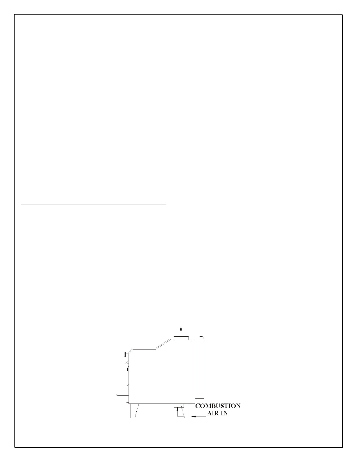
FREESTANDING STOVE LEG REQUIREMENTS
All Country Flame freestanding catalytic stoves have a Queen Ann leg system available for purchase. This leg kit includes
four Queen Anne legs that are available in a number of optional finishes and all mounting hardware required by the
installer. Please contact Country Flame or a local authorized dealer to discuss optional finishes and to order a Queen
Anne leg kit.
1. Refer to FIGURE 5 for a diagram and refer to this paragraph’s instructions on how to mount the Queen Anne leg
kit to a Model R catalytic stove. If the installer is working with a different model catalytic stove, the instructions and
mounting procedures are the same as the Model R.
a. Locate the eight (8) bolts that are included with the four Queen Anne Legs.
b. Bolt and tighten each leg to the stove using two bolts. DO NOT OVER TIGHTEN THE BOLTS AS
DAMAGE MAY OCCUR. Ensure each leg is positioned properly so the leg is facing towards the front of the stove.
c. Position the stove on a level surface. Adjust the leveling bolts in the legs in order to level the stove to the
floor, as necessary. Ensure that clearances to combustibles are maintained once the stove has been set in its final position.
TO CHIMNEY
FIGURE 5: QUEEN ANNE LEG INSTALLATION
20
STOVE INSTALLATION PREPARATION
1 Prepare the stove for installation by removing it from its shipping container. Discard all packaging material in an
appropriate waste container. WARNING: Do not throw away any stove parts that are included with the stove.
2 The installer and homeowner should familiarize themselves with the stove and adhere to ALL warning labels.
Protect the gold trim from any physical damage.
3 Ensure that a code approved electrical power outlet has been installed for later use with the stove’s blower system.
4 The installer or homeowner should IMMEDIATELY inspect the stove for any physical damage that may have
occurred during shipment. The fact that the package was NOT DAMAGED does not mean that the stove was not
damaged in shipping. Report all damage immediately to the shipper, the dealer, and Country Flame.
5 Check all stove controls for movement. In the event the stove was dropped during shipment, a jammed control
can be costly to fix. The stove controls should move freely before the stove is installed. Report all damage to the shipper,
dealer, and Country Flame.
6 TABLE 4 and TABLE 5 serve as a guide on equipment that is available with each stove.
TABLE 4: FREE STANDING MODELS
FREESTANDING
MODEL B
MODEL BBF
MODEL R
TEMP
PROBE
STANDARD RECTANGULAR STANDARD OPTION OPTIONAL
STANDARD RECTANGULAR STANDARD OPTION OPTIONAL
STANDARD RECTANGULAR OPTION OPTION OPTIONAL*
CATALYST BLOWER QUEEN
ANN
LEGS
FLUE
COLLAR
TABLE 5: INSERT MODELS
INSERTS TEMP
PROBE
MODEL B
MODEL BBF
MODEL O2
STANDARD RECTANGULAR STANDARD OPTION OPTION
STANDARD RECTANGULAR STANDARD OPTION OPTION
STANDARD ROUND STANDARD OPTION OPTION
NOTES:
1 SHROUDS ARE SOMETIMES REFERRED TO AS PANELS OR TRIM.
2 OTHER OPTIONAL ITEMS MAY BE AVAILABLE FOR THE CATALYTIC STOVES, CHECK WITH A
DEALER OR COUNTRY FLAME.
3 CHECK THE OWNERS MANUAL FOR SPECIFIC ITEMS PROVIDED WITH A CATALYTIC STOVE OR
CONSULT A DEALER OR COUNTRY FLAME.
CATALYST BLOWER FLUE
ADAPTOR
TRANSITION
SHROUD
TRIM
21
FACTORY BUILT FIREPLACES
Country Flame catalytic stoves are approved for installation in factory built wood burning fireplaces. Any fireplace used
to install a Country Flame catalytic stove should be listed to UL 127 or ULC S610 standards. Further, Country Flame
stoves have been specifically tested and approved for installation in the following manufacturer’s fireplaces: Heatilator,
Superior, Preway, Marco, Majestic, Martin. The approval to install one of Country Flames stoves in one of these
manufacturers’ fireplaces extends to all models if it meets one condition. A minimum clearance (air space) of 1” (25mm)
is to be maintained from the sides, back and top between the zero clearance fireboxes and the Country Flame catalytic
stove once installation has been completed. Only two modifications may be made to any zero clearance fireplaces before
installing a Country Flame catalytic stove:
1 The damper may be removed from the existing fireplace. If the damper is not removable, it must be permanently
wired into the open position before the catalytic stove is installed and,
2 The ember catcher, located in the base of the fireplace flue, may be permanently removed before the catalytic
stove is installed.
NOTE: Any parts removed from an existing fireplace should be properly stored. In the event the catalytic stove is
removed, these fireplace parts would need to be reinstalled. Failure to reinstall a removed part will create a dangerous
situation during fireplace operation.
MASONRY BUILT FIREPLACES
Country Flame catalytic stoves are approved for installation in masonry built fireplaces constructed in accordance with the
requirements of the Standard for Chimneys, Fireplaces, Vents, and Solid Fuel Burning Appliances in accordance with
NFPA Number 211, UBC 37 standards, or any applicable local code requirements. Carefully plan the installation in order
to avoid costly mistakes. First, be sure to understand clearance requirements and ensure the Country Flame catalytic stove
model selected for the home will fit into an existing masonry built fireplace. An installation in masonry built fireplaces
requires that the damper be secured into the open position. Although Country Flame catalytic stoves have been approved
for “face seal” installation only, Country Flame STRONGLY recommends the use of one of the following techniques
when deciding on a chimney connection:
a) GOOD – Minimum of 12” (300mm) starter pipe installed into fireplace flue.
b) BETTER – Direct connection of a chimney liner past the first clay flue tile in
accordance with NFPA 211 or any applicable local code.
c) BEST - Install a complete relining of the masonry chimney system with an 8”
(200mm) diameter standard steel chimney connector.
Kits are available to assist in the connection of a catalytic stove to a masonry fireplace chimney. Look for a listed kit,
which means it has agency approval. The stove to fireplace kit is to be installed in place of the fireplace damper. In most
cases, the existing fireplace damper will be removed to allow for installation of the kit adaptor. The critical points are that:
(1) The stove connector pipe (either 6” [150mm] or 8” [200mm]) must extend up the masonry chimney past the first clay
flue tile and (2) The adaptor and chimney connector must fit tightly and be sealed with high temperature furnace cement.
The adaptor kit’s instructions must be followed over any information provided in this manual.
DO NOT REMOVE BRICK OR MORTAR FROM THE FIREPLACE IN ORDER TO INSTALL ANY STOVE
OR ADAPTOR KIT. FIREPLACE INSERT FLOOR PROTECTORS MUST EXTEND AT LEAST 8” (200MM)
TO EACH SIDE AND 18” (450MM) IN FRONT.
Have the masonry fireplace inspected by a certified installer or chimney sweep. Inspect for loose mortar, cracks, broken
clay liners, deterioration, blockage of the flue, etc. The existing masonry chimney system should be certified for use with
a catalytic stove. If the masonry chimney has an oversized flue, it will contribute to poor draft, creosote build up and
other problems. A chimney’s flue size should be no less than the existing diameter of a stove’s flue collar and no more
than three (3) times the cross sectional area of the flue size of the catalytic stove’s flue collar. EXAMPLE: Assume the
22
stove’s flue collar has an inside diameter of 6”. This means the stove’s flue area is approximately 28 square inches, which
means the chimney’s cross sectional flue area cannot exceed 84 square inches. Thus, if the clay tile inside the chimney has
a dimension larger than 8” (200mm) by 8” (200mm) a full liner would need to be installed in the chimney flue to ensure
proper stove draft. The installer should ensure that the proper size chimney tile is installed over the full length of the
chimney. If not, install a properly sized liner to ensure optimal performance.
DRAFT
A good draft is necessary for the proper operation of any stove. Draft is the force created as warm flue gases move up the
chimney and pull fresh air into the stove. Any restriction either at the exhaust or intake ends of the chimney will affect
draft. The amount of draft in the chimney system depends on the length of the chimney, the local geography, nearby
obstructions, prevailing winds, etc. A draft gauge should measure somewhere between 0.05 to 0.07 inches of water
column (W.C.) for the stove to operate efficiently.
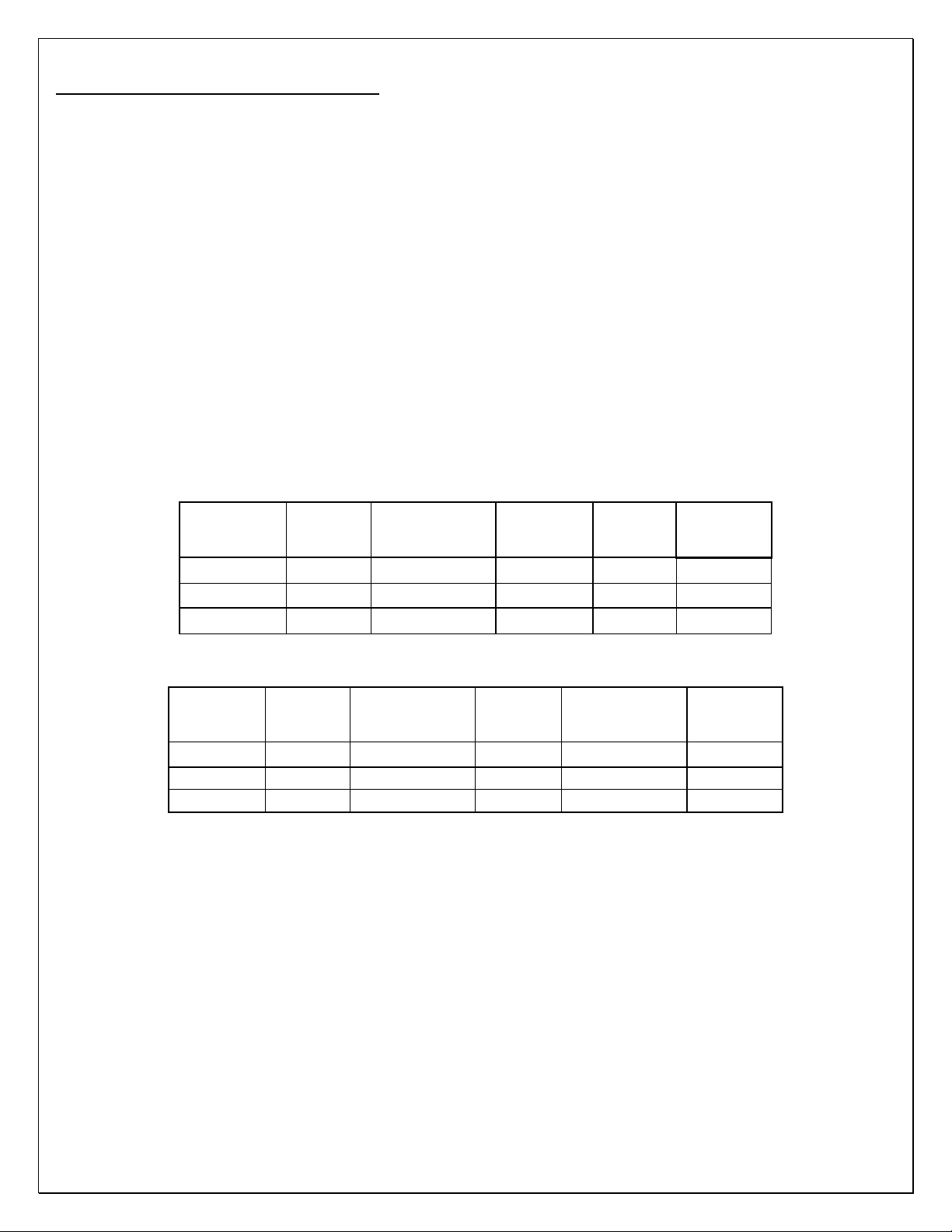
MINIMUM CLEARANCES
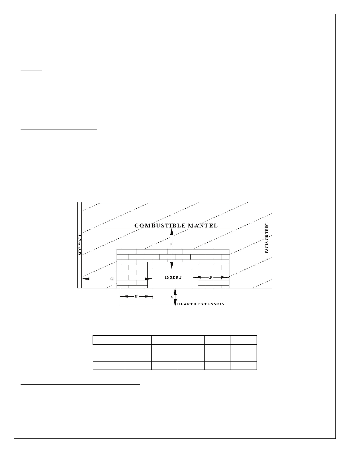
When installing a catalytic stove into an existing fireplace, ensure that all minimum clearances shown in FIGURE 7 and
defined in TABLE 6 are maintained during installation. Failure to maintain these minimum clearances can create
overheating of the fireplace, the stove, or surrounding combustible materials. Do not seal over the face of any chimney or
air-cooling system of the existing fireplace system. Failure to maintain the proper clearances during installation voids the
Country Flame warranty. Always refer to the Safety Label on the
rear of the specific Country Flame stove being
installed for the latest clearance and installation instructions.
FIGURE 7: INSERT MINIMUM CLEARANCE REQUIREMENTS
TABLE 6: INSERT MINIMUM CLEARANCES, IN INCHES
MODEL A B C D E
BBF
B
O2
18" 8" 21" 10" 26"
18" 8" 18" 8" 16"
18" 8" 14" 8" 24"
FLOOR PROTECTION REQUIREMENTS
1. All Country Flame freestanding catalytic wood stoves require a listed floor protector that is noncombustible.
Country Flame catalytic stoves were tested with a listed floor protection that had a thermal conductivity of K =
0.85 BTU-inch per hour per square foot per degree Fahrenheit and that was 3/8” thick (9.5mm) non-asbestos
millboard. Refer to FIGURE 8 and TABLE 7 for floor protector information.
23

FIGURE 8: FLOOR PROTECTOR DIMENSIONS
MODEL BBF B R
G
H
I
8 8 8
18 18 16
8 8 3
TABLE 7: MINIMUM DIMENSIONS OF FLOOR PROTECTOR (in inches)
2. If a floor protector, different from the tested floor protector, is to be used, it must meet or exceed the requirements of
the listed R-value of the tested floor protector. To convert alternate floor protectors to their respective R value use the
following procedures:
a. Convert floor material specification to R-value.
i. R-value is given – no conversion is required.
ii. k-factor is given with required thickness (T) in inches: R = (1/k) x T.
iii. C-factor given: R = 1/C.
b. Determine the R-value of the proposed alternate floor protector.
i. Use the formulas provided in STEP 2 to convert values not expressed as “R.”
ii. For multiple layers of material, add each R-value of each layer to determine the materials overall R-
Value.
c. If the overall R-value of the alternate material is greater than the tested material defined in STEP 1, then the
alternate floor protection is acceptable.
d. EXAMPLE:
i. The tested material was 3/8 inch thick with a k-factor of 0.85.
ii. The R-value of the tested material was R = (1/0.85) x 3/8 = 0.44.
iii. Suppose the tested material is to be replaced by 4-inch brick material with a C of 1.25.
iv. The R-value of the alternate brick material is R = (1/1.25) = 0.80. Since the R-value of the alternate brick
material [R = 0.80] is greater than the tested material’s R-value [R = 0.44] then the alternate material is acceptable
for use in the specific application.
3. Listed Floor Protector Definitions:
b. Thermal Conductance = C = Btu/(hr)(ft
c. Thermal Conductivity = k = (Btu)(inch)/(hr)(ft
d. Thermal Resistance = R = (ft
2
)(hr)(OF)/Btu = (m2)(OK)/W
e. HEARTH EXTENSIONS must have an R-value greater than to ensure proper combustible floor protection.
2)(O
F) = W/(m2)(OK)
2)(O
F) = W/(m)(OK) = Btu/(hr)(ft)(OF)
24
4. WARNING: A catalytic stove must always be placed on a listed floor protector if the existing floor where the stove
is to be placed is made of any combustible material. IF THE AREA WHERE THE STOVE IS TO BE PLACED IS
CARPETED, THE CARPET MUST BE REMOVED. A LISTED FLOOR PROTECTOR IS NEVER TO BE
PLACED ON CARPET. CHECK LOCAL CODES FOR ADDITIONAL CARPET RESTRICTIONS AND FLOOR
PROTECTION REQUIREMENTS.
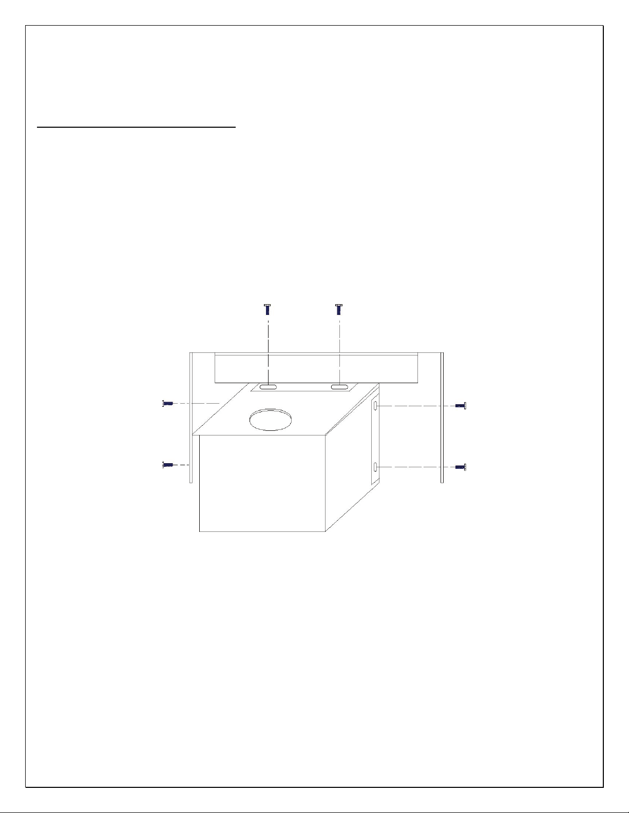
SHROUD AND TRIM INSTALLATION
Each Country Flame insert can be installed with an optional shroud and trim package. There are three shroud and trim
packages available for each catalytic stove depending on the installation requirements. There is the (a) standard shroud kit,
(b) the oversized shroud kit, and (c) the custom shroud kit. The size of the fireplace opening and the surrounding fireplace
facing will determine which one of these kits will be selected by the installer or homeowner. In the event there is any
confusion, about which one to select, the local Country Flame Dealer or Country Flame will be able to assist in the
selection of the appropriate shroud kit.
Once the stove is properly located in the opening, leveled on the floor, and installed in its finished position, the installer
would pull the stove out from the fireplace in order to install a shroud kit on the catalytic stove. FIGURE 9 shows a
shroud kit on a generic stove; however, each Country Flame shroud kit comes with detailed instructions for use in
installing the kit on a specific model stove. Refer to these instructions and in the event of any confusion, contact Country
Flame or its local dealer to assist with clarification.
FIGURE 9: SHROUD AND TRIM INSTALLATION
25
 Loading...