

Page 1
Mounting the camera (continued)
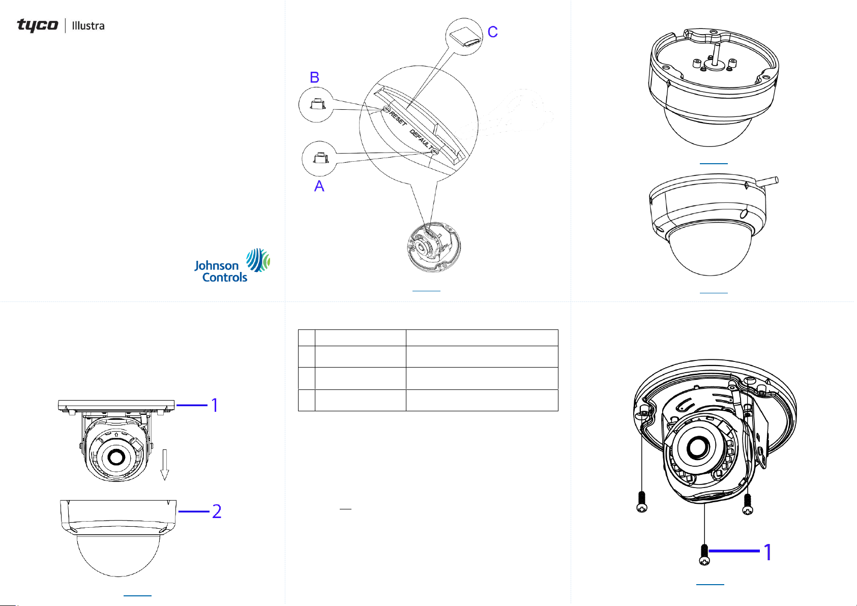
Figure 3
Figure 4
Security
Quick Start Guide
(8200-1929-01_B0)
Essential Gen4 2MP Fixed & Varifocal Dome Cameras
In the box
1 x Essentials Indoor / Outdoor Dome camera
1 x Printed Quick Guide
1 x Desiccant
1 x Torx Wrench
3 x Plastic Anchors
3 x Tapping Screws
1 x Mounting Guide Pattern
Installation tools
Drill
Screwdrivers
Wire cutters
Quick reference
Default IP: 192.168.1.168 (DHCP enabled)
Default Username: admin
Default Password: admin
Power: 12Vdc / PoE (IEEE 802.3af Class 3)
Disassembling the camera.
A. Use the Torx wrench to loosen the three screws on the camera top
cover (1) (Figure 1) and gently remove the cover (2) (Figure 1).
Figure 1
Figure 2: Internal Interface pictorial index
Figure 2
Table 1: Internal interface pictorial index descriptions
Name
Description
A
Reboot Button
Press and release the button to reboot the
camera.
B
Reset Button
Press the button for 1 second to reboot the
camera.
C
Micro SD card slot
Insert a micro SD card into the slot for video
recording and file storage.
Mounting the camera
A. Place the mounting template on the wall / ceiling and drill three
Ø4.5mm holes.
B. Insert the three plastic anchors into the three holes.
C. Determine how the camera pigtail cable should be routed:
Through the cable entry on top of the camera (Figure 3).
Note: If required then drill a cable hole on the wall as identified
on the mounting template.
OR
Through the cable side entry slot (Figure 4).
Note: You do not need to drill a cable hole as identified in the
mounting template when using the cable side entry slot.
D. Route the camera pigtail cable as per one of the options in step C and
place the camera onto the wall / ceiling and align the three holes on the
camera with three holes on the wall / ceiling.
Mounting the camera (continued)
E. Insert the three tapping screws (1) (Figure 5) into the three holes on
the camera body and using the screw driver securely attach the
camera to the wall / ceiling.
Figure 5
Page 2

Security
Adjusting the camera position
The camera has three axes to adjust the field of view for different applications
(Figure 6). While screening live view on your monitor, adjust the axes as per
the information below on the next page.
Figure 6
Adjusting the camera position (continued)
Pan Adjustment (A - Figure 6) Rotate the lens base until satisfied
with the field of view. Please DO NOT rotate over the default limit of
˃355°.
Tilt Adjustment (B – Figure 6) Tilt the camera lens within the certain
range (70°) to your desired field of view.
Horizontal Rotation (C – Figure 6) Rotate the 3D assembly in the
lens, DO NOT turn the assembly more than the limit (± 355°) as this
may result in the internal cables becoming twisted, disconnected, or
broken.
Assembling the camera
A. Place the camera top cover (2) (Figure 7) onto the camera body (1)
(Figure 7).
B. Use the Torx wrench to securely attach the three Torx screws located
on the camera top cover (2) (Figure 7).
Assembling the camera (continued)
Figure 7
Powering up the camera
12Vdc: Connect the 12Vdc cable to the DC 12V terminal.
OR
PoE: Connect the RJ-45 jack to a PoE compatible network device that
supplies power through the Ethernet cable.
Warnings
This product is intended for professional installation, please follow local
wiring regulations.
To meet EU security immunity requirements this product should be used
with a Uninterruptable Power Supply to feed the mains input of any
power adaptor
The product should be powered by a limited power supply (LPS) sized
according to the product rating label.
The LAN symbol on the unit means this is not intended for connection to
a public network or a LAN from a different building.
Do not install where children are likely to have access.
© 2020 Johnson Controls. All rights reserved.
JOHNSON CONTROLS, TYCO and ILLUSTRA are trademarks and/or
registered trademarks. Unauthorized use is strictly prohibited.
 Loading...