

Page 1

Configuration and User Guide
VideoEdge® IP SpeedDome Camera
Version 1.0
Part Number 8200-2613-01 C0
Page 2

Notice
The information in this manual was current when published. The manufacturer reserves the right to revise and improve its
products. All specifications are therefore subject to change without notice.
Copyright
Under copyright laws, the contents of this manual may not be copied, photocopied, reproduced, translated or reduced to
any electronic medium or machine-readable form, in whole or in part, without prior written consent of Tyco International
Ltd.
© Copyright 2009 and its Respective Companies. All Rights Reserved,
Customer Service
Thank you for using American Dynamics products. We support our products through an extensive worldwide network of
dealers. The dealer through whom you originally purchased this product is your point of contact if you need service or
support. Our dealers are empowered to provide the very best in customer service and support. Dealers should contact
American Dynamics at (800) 507-6268 or (561) 912-6259 or on the Web at www.americandynamics.net.
Trademarks
Windows® is a registered trademark of Microsoft Corporation. PS/2® is a registered trademark of International Business
Machines Corporation.
Trademarked names are used throughout this manual. Rather than place a symbol at each occurrence, trademarked
names are designated with initial capitalization. Inclusion or exclusion is not a judgment on the validity or legal status of the
term.
License Information
Your use of this product is governed by certain terms and conditions. Please see the detailed license information at the end
of this manual.
ii Configuration and User Guide
Page 3
Warning
To Reduce Risk of electric shock, do not remove cover. No user serviceable parts inside. Refer servicing to qualified
service personnel.
Do not expose this appliance to rain or moisture.
Do not install this product in hazardous areas where highly combustible or explosive products are
stored or used.
The lightning flash/arrowhead symbol, within an equilateral triangle, alerts the user to the presence
of a shock hazard within the product’s enclosure.
IT E161302
Underwriters Laboratories Inc. (“UL”) has not tested the performance or reliability of the security or
signaling aspects of this product. UL has only tested for fire, shock or casualty hazards as outlined
in the UL's Standard for Safety UL 60950-1. UL Certification does not cover the performance
or reliability of the security or signaling aspects of this product. UL makes no
representations, warranties or certifications whatsoever regarding the performance or
reliability of any security or signaling related functions of this product.
Note to Camera System Installer - This reminder is provided to call the camera systems
installer's attention to Section 820.93 of the National Electrical Code, ANSI/NFPA 70: 2005, which
provide guidelines for proper grounding and, in particular, specify that the coaxial cable shield shall
be connected to the grounding system of the building, as close to the point of cable entry as
practical.
This equipment has been tested and found to comply with the limits for a Class “A” digital device,
pursuant to part 15 of the FCC Rules. These limits are designed to provide reasonable protection
against harmful interference when the equipment is operated in a commercial environment. This
equipment generates, uses and can radiate radio frequency energy and, if not installed and used
in accordance with the instruction manual, may cause interference to radio communications.
Operation of this equipment in a residential area is likely to cause harmful interference in which
case the user will be required to correct the interference at their own expense.
Changes or modifications not expressly approved by Sensormatic the party responsible for FCC
compliance, could void the user’s authority to operate the equipment.
Certified Limited Power Required. This installation should be made by a qualified service person
and should conform to all local codes. For outdoor installations use liquid-tight conduit or liquidtight pipe.
This class A digital apparatus complies with Canadian ICES-003.
Cet appareil numérique de la classe A est conforme à la norme NMB-003 du Canada.
Refer to the Configuration and User Guide contained on the CD for more information.
iii
Page 4

iv Configuration and User Guide
Page 5

Table of Contents
Introduction 1
Overview . . . . . . . . . . . . . . . . . . . . . . . . . . . . . . . . . . . . . . . . . . . . . . . . . . . . . . . . . 1-1
Features . . . . . . . . . . . . . . . . . . . . . . . . . . . . . . . . . . . . . . . . . . . . . . . . . . . . . . . . . . 1-2
ACC compression . . . . . . . . . . . . . . . . . . . . . . . . . . . . . . . . . . . . . . . . . . . . . . . . 1-2
Frame Rates . . . . . . . . . . . . . . . . . . . . . . . . . . . . . . . . . . . . . . . . . . . . . . . . . . . . 1-2
Resolutions . . . . . . . . . . . . . . . . . . . . . . . . . . . . . . . . . . . . . . . . . . . . . . . . . . . . . 1-2
Video loss detection . . . . . . . . . . . . . . . . . . . . . . . . . . . . . . . . . . . . . . . . . . . . . . 1-2
Bandwidth Throttling . . . . . . . . . . . . . . . . . . . . . . . . . . . . . . . . . . . . . . . . . . . . . . 1-2
Web Configuration. . . . . . . . . . . . . . . . . . . . . . . . . . . . . . . . . . . . . . . . . . . . . . . . 1-3
Installation 2
Minimum System Requirements . . . . . . . . . . . . . . . . . . . . . . . . . . . . . . . . . . . . . 2-1
Mounts. . . . . . . . . . . . . . . . . . . . . . . . . . . . . . . . . . . . . . . . . . . . . . . . . . . . . . . . . 2-1
Installation Process . . . . . . . . . . . . . . . . . . . . . . . . . . . . . . . . . . . . . . . . . . . . . . . 2-2
Install and Detect the IP Dome . . . . . . . . . . . . . . . . . . . . . . . . . . . . . . . . . . . . . . 2-3
Installation using DHCP and Bonjour for Windows . . . . . . . . . . . . . . . . . . . . . 2-3
Installation without a DCHP Server using a Static IP Address . . . . . . . . . . . . 2-4
ActiveX Installation . . . . . . . . . . . . . . . . . . . . . . . . . . . . . . . . . . . . . . . . . . . . . . . 2-5
Web Configuration 3
Log in to the IP Dome . . . . . . . . . . . . . . . . . . . . . . . . . . . . . . . . . . . . . . . . . . . . . 3-2
User Accounts . . . . . . . . . . . . . . . . . . . . . . . . . . . . . . . . . . . . . . . . . . . . . . . . . 3-2
Administrator. . . . . . . . . . . . . . . . . . . . . . . . . . . . . . . . . . . . . . . . . . . . . . . . . 3-3
Recorder . . . . . . . . . . . . . . . . . . . . . . . . . . . . . . . . . . . . . . . . . . . . . . . . . . . . 3-4
User . . . . . . . . . . . . . . . . . . . . . . . . . . . . . . . . . . . . . . . . . . . . . . . . . . . . . . . 3-5
Checking Camera Feed using the Live Viewing function . . . . . . . . . . . . . . . . . . 3-6
Controlling dome cameras on the Live Viewing page . . . . . . . . . . . . . . . . . . . 3-7
Dome Camera Controls . . . . . . . . . . . . . . . . . . . . . . . . . . . . . . . . . . . . . . . . 3-7
Controlling the Pan-Tilt Control via Mouse . . . . . . . . . . . . . . . . . . . . . . . . . . 3-9
Zoom via Mouse Scroll Wheel . . . . . . . . . . . . . . . . . . . . . . . . . . . . . . . . . . . 3-9
Live Viewing Menu 4
Video . . . . . . . . . . . . . . . . . . . . . . . . . . . . . . . . . . . . . . . . . . . . . . . . . . . . . . . . . . 4-1
Presets . . . . . . . . . . . . . . . . . . . . . . . . . . . . . . . . . . . . . . . . . . . . . . . . . . . . . . . . 4-3
Using Preset as Home Position . . . . . . . . . . . . . . . . . . . . . . . . . . . . . . . . . . . . 4-6
Patterns . . . . . . . . . . . . . . . . . . . . . . . . . . . . . . . . . . . . . . . . . . . . . . . . . . . . . . . . 4-7
Using Pattern as Home Position . . . . . . . . . . . . . . . . . . . . . . . . . . . . . . . . . . 4-10
Scans/Sequences . . . . . . . . . . . . . . . . . . . . . . . . . . . . . . . . . . . . . . . . . . . . . . . 4-12
v
Page 6

Table of Contents
Scans . . . . . . . . . . . . . . . . . . . . . . . . . . . . . . . . . . . . . . . . . . . . . . . . . . . . . . . 4-12
Using Scan as Home Position . . . . . . . . . . . . . . . . . . . . . . . . . . . . . . . . . . . . 4-13
Sequences . . . . . . . . . . . . . . . . . . . . . . . . . . . . . . . . . . . . . . . . . . . . . . . . . . . 4-14
Using Sequence as Home Position . . . . . . . . . . . . . . . . . . . . . . . . . . . . . . . . 4-14
Privacy Zones . . . . . . . . . . . . . . . . . . . . . . . . . . . . . . . . . . . . . . . . . . . . . . . . . . 4-17
Privacy Zone Settings . . . . . . . . . . . . . . . . . . . . . . . . . . . . . . . . . . . . . . . . . . 4-17
Stored Audio . . . . . . . . . . . . . . . . . . . . . . . . . . . . . . . . . . . . . . . . . . . . . . . . . . . 4-24
Audio File Requirements . . . . . . . . . . . . . . . . . . . . . . . . . . . . . . . . . . . . . . . . 4-24
Camera Adjust. . . . . . . . . . . . . . . . . . . . . . . . . . . . . . . . . . . . . . . . . . . . . . . . . . 4-28
Electronic Image Stabilization and Wide Dynamic Range . . . . . . . . . . . . . . . 4-28
Wide Dynamic Range . . . . . . . . . . . . . . . . . . . . . . . . . . . . . . . . . . . . . . . . . . 4-29
Focus and Iris Control . . . . . . . . . . . . . . . . . . . . . . . . . . . . . . . . . . . . . . . . . . 4-30
De-Interlacing. . . . . . . . . . . . . . . . . . . . . . . . . . . . . . . . . . . . . . . . . . . . . . . . . 4-31
Automatic White Balance. . . . . . . . . . . . . . . . . . . . . . . . . . . . . . . . . . . . . . . . 4-33
Infra Red Features . . . . . . . . . . . . . . . . . . . . . . . . . . . . . . . . . . . . . . . . . . . . . 4-36
IR Mode . . . . . . . . . . . . . . . . . . . . . . . . . . . . . . . . . . . . . . . . . . . . . . . . . . . 4-36
Day/Night Mode . . . . . . . . . . . . . . . . . . . . . . . . . . . . . . . . . . . . . . . . . . . . . 4-37
North Position . . . . . . . . . . . . . . . . . . . . . . . . . . . . . . . . . . . . . . . . . . . . . . . . 4-39
Shutter Limit. . . . . . . . . . . . . . . . . . . . . . . . . . . . . . . . . . . . . . . . . . . . . . . . . . 4-40
Automatic Gain Control. . . . . . . . . . . . . . . . . . . . . . . . . . . . . . . . . . . . . . . . 4-40
Shutter Speed . . . . . . . . . . . . . . . . . . . . . . . . . . . . . . . . . . . . . . . . . . . . . . . 4-42
Picture . . . . . . . . . . . . . . . . . . . . . . . . . . . . . . . . . . . . . . . . . . . . . . . . . . . . . . 4-44
Camera Menu 5
PTZ Configuration . . . . . . . . . . . . . . . . . . . . . . . . . . . . . . . . . . . . . . . . . . . . . . . . 5-1
Automatic Flip . . . . . . . . . . . . . . . . . . . . . . . . . . . . . . . . . . . . . . . . . . . . . . . . . 5-2
Zoom Stop . . . . . . . . . . . . . . . . . . . . . . . . . . . . . . . . . . . . . . . . . . . . . . . . . . . . 5-2
22X Camera Dome . . . . . . . . . . . . . . . . . . . . . . . . . . . . . . . . . . . . . . . . . . . . 5-2
35X Camera Dome . . . . . . . . . . . . . . . . . . . . . . . . . . . . . . . . . . . . . . . . . . . . 5-3
Freeze Frame . . . . . . . . . . . . . . . . . . . . . . . . . . . . . . . . . . . . . . . . . . . . . . . . . 5-3
Return Settings . . . . . . . . . . . . . . . . . . . . . . . . . . . . . . . . . . . . . . . . . . . . . . . . 5-4
Return to Auto Focus/Auto Iris . . . . . . . . . . . . . . . . . . . . . . . . . . . . . . . . . . . 5-4
Return to Previous . . . . . . . . . . . . . . . . . . . . . . . . . . . . . . . . . . . . . . . . . . . . 5-4
Current Home Position. . . . . . . . . . . . . . . . . . . . . . . . . . . . . . . . . . . . . . . . . . . 5-4
Overlay Settings . . . . . . . . . . . . . . . . . . . . . . . . . . . . . . . . . . . . . . . . . . . . . . . . . 5-6
Camera Name . . . . . . . . . . . . . . . . . . . . . . . . . . . . . . . . . . . . . . . . . . . . . . . . . 5-6
Camera Status . . . . . . . . . . . . . . . . . . . . . . . . . . . . . . . . . . . . . . . . . . . . . . . . . 5-7
Dome Names . . . . . . . . . . . . . . . . . . . . . . . . . . . . . . . . . . . . . . . . . . . . . . . . . . 5-7
Time/Direction Indicators . . . . . . . . . . . . . . . . . . . . . . . . . . . . . . . . . . . . . . . . . 5-7
Text Attributes . . . . . . . . . . . . . . . . . . . . . . . . . . . . . . . . . . . . . . . . . . . . . . . . . 5-8
Areas . . . . . . . . . . . . . . . . . . . . . . . . . . . . . . . . . . . . . . . . . . . . . . . . . . . . . . . . . 5-10
Areas List . . . . . . . . . . . . . . . . . . . . . . . . . . . . . . . . . . . . . . . . . . . . . . . . . . . . 5-10
Alarms . . . . . . . . . . . . . . . . . . . . . . . . . . . . . . . . . . . . . . . . . . . . . . . . . . . . . . . . 5-13
Alarm Actions. . . . . . . . . . . . . . . . . . . . . . . . . . . . . . . . . . . . . . . . . . . . . . . . . 5-13
Add Sequence. . . . . . . . . . . . . . . . . . . . . . . . . . . . . . . . . . . . . . . . . . . . . . . . . . 5-16
Sequence Names . . . . . . . . . . . . . . . . . . . . . . . . . . . . . . . . . . . . . . . . . . . . . 5-16
vi Configuration and User Guide
Page 7

Table of Contents
Scheduled Tasks. . . . . . . . . . . . . . . . . . . . . . . . . . . . . . . . . . . . . . . . . . . . . . . . 5-19
Task Details . . . . . . . . . . . . . . . . . . . . . . . . . . . . . . . . . . . . . . . . . . . . . . . . . . 5-19
Video . . . . . . . . . . . . . . . . . . . . . . . . . . . . . . . . . . . . . . . . . . . . . . . . . . . . . . . . . 5-22
Audio . . . . . . . . . . . . . . . . . . . . . . . . . . . . . . . . . . . . . . . . . . . . . . . . . . . . . . . . . 5-24
Networking Menu 6
Date Time . . . . . . . . . . . . . . . . . . . . . . . . . . . . . . . . . . . . . . . . . . . . . . . . . . . . . . 6-1
Date Time Format . . . . . . . . . . . . . . . . . . . . . . . . . . . . . . . . . . . . . . . . . . . . . . 6-1
Setting Camera Time . . . . . . . . . . . . . . . . . . . . . . . . . . . . . . . . . . . . . . . . . . . . 6-2
TCP/IP. . . . . . . . . . . . . . . . . . . . . . . . . . . . . . . . . . . . . . . . . . . . . . . . . . . . . . . . . 6-4
DHCP Configuration . . . . . . . . . . . . . . . . . . . . . . . . . . . . . . . . . . . . . . . . . . . . 6-4
IP Address Configuration . . . . . . . . . . . . . . . . . . . . . . . . . . . . . . . . . . . . . . . . . 6-4
DNS Configuration . . . . . . . . . . . . . . . . . . . . . . . . . . . . . . . . . . . . . . . . . . . . . . 6-5
Users . . . . . . . . . . . . . . . . . . . . . . . . . . . . . . . . . . . . . . . . . . . . . . . . . . . . . . . . . . 6-6
User Administration . . . . . . . . . . . . . . . . . . . . . . . . . . . . . . . . . . . . . . . . . . . . . 6-6
SMTP Settings . . . . . . . . . . . . . . . . . . . . . . . . . . . . . . . . . . . . . . . . . . . . . . . . . . 6-8
Email Settings . . . . . . . . . . . . . . . . . . . . . . . . . . . . . . . . . . . . . . . . . . . . . . . . . 6-8
Email Test . . . . . . . . . . . . . . . . . . . . . . . . . . . . . . . . . . . . . . . . . . . . . . . . . . . . 6-9
FTP Settings . . . . . . . . . . . . . . . . . . . . . . . . . . . . . . . . . . . . . . . . . . . . . . . . . . . 6-10
FTP Settings . . . . . . . . . . . . . . . . . . . . . . . . . . . . . . . . . . . . . . . . . . . . . . . . . 6-10
Firewall . . . . . . . . . . . . . . . . . . . . . . . . . . . . . . . . . . . . . . . . . . . . . . . . . . . . . . . 6-12
Maintenance . . . . . . . . . . . . . . . . . . . . . . . . . . . . . . . . . . . . . . . . . . . . . . . . . . . 6-14
HTTPS Certificate . . . . . . . . . . . . . . . . . . . . . . . . . . . . . . . . . . . . . . . . . . . . . 6-16
Advanced . . . . . . . . . . . . . . . . . . . . . . . . . . . . . . . . . . . . . . . . . . . . . . . . . . . . . 6-18
Bandwidth Throttling . . . . . . . . . . . . . . . . . . . . . . . . . . . . . . . . . . . . . . . . . . . 6-19
Bonjour. . . . . . . . . . . . . . . . . . . . . . . . . . . . . . . . . . . . . . . . . . . . . . . . . . . . . . 6-19
Zero Configuration Networking . . . . . . . . . . . . . . . . . . . . . . . . . . . . . . . . . . 6-20
Implementation . . . . . . . . . . . . . . . . . . . . . . . . . . . . . . . . . . . . . . . . . . . . . . 6-20
Address Assignment . . . . . . . . . . . . . . . . . . . . . . . . . . . . . . . . . . . . . . . . . . 6-20
Service Discovery . . . . . . . . . . . . . . . . . . . . . . . . . . . . . . . . . . . . . . . . . . . . 6-20
Information Menu 7
Model. . . . . . . . . . . . . . . . . . . . . . . . . . . . . . . . . . . . . . . . . . . . . . . . . . . . . . . . . . 7-1
Statistics . . . . . . . . . . . . . . . . . . . . . . . . . . . . . . . . . . . . . . . . . . . . . . . . . . . . . . . 7-2
Environmental . . . . . . . . . . . . . . . . . . . . . . . . . . . . . . . . . . . . . . . . . . . . . . . . . . . 7-4
System Log . . . . . . . . . . . . . . . . . . . . . . . . . . . . . . . . . . . . . . . . . . . . . . . . . . . . . 7-5
Boot Log . . . . . . . . . . . . . . . . . . . . . . . . . . . . . . . . . . . . . . . . . . . . . . . . . . . . . . . 7-6
Current Faults . . . . . . . . . . . . . . . . . . . . . . . . . . . . . . . . . . . . . . . . . . . . . . . . . . . 7-7
Fault Details . . . . . . . . . . . . . . . . . . . . . . . . . . . . . . . . . . . . . . . . . . . . . . . . . . . 7-8
DIOM (Digital Input Output Monitor) Faults. . . . . . . . . . . . . . . . . . . . . . . . . . 7-8
ENVM (Environmental Monitor) Faults . . . . . . . . . . . . . . . . . . . . . . . . . . . . . 7-8
ENVM Card Upgrade Progress. . . . . . . . . . . . . . . . . . . . . . . . . . . . . . . . . . . 7-8
Change Password . . . . . . . . . . . . . . . . . . . . . . . . . . . . . . . . . . . . . . . . . . . . . . . . 7-9
vii
Page 8

Table of Contents
Camera Recovery . . . . . . . . . . . . . . . . . . . . . . . . . . . . . . . . . . . . . . . . . . . . . . . . . . 8-1
Physical Factory Reset . . . . . . . . . . . . . . . . . . . . . . . . . . . . . . . . . . . . . . . . . . . . . . 8-3
Technical specification 9
Technical Specifications . . . . . . . . . . . . . . . . . . . . . . . . . . . . . . . . . . . . . . . . . . . 9-1
Camera Specifications . . . . . . . . . . . . . . . . . . . . . . . . . . . . . . . . . . . . . . . . . . . . 9-2
Compression . . . . . . . . . . . . . . . . . . . . . . . . . . . . . . . . . . . . . . . . . . . . . . . . . . . . 9-3
CODEC Combinations . . . . . . . . . . . . . . . . . . . . . . . . . . . . . . . . . . . . . . . . . . . . 9-3
Alarm Buffering . . . . . . . . . . . . . . . . . . . . . . . . . . . . . . . . . . . . . . . . . . . . . . . . . . 9-3
Certification and Regulations . . . . . . . . . . . . . . . . . . . . . . . . . . . . . . . . . . . . . . . 9-5
User Account Privileges 10
Site Maps 11
Live Viewing Site Map . . . . . . . . . . . . . . . . . . . . . . . . . . . . . . . . . . . . . . . . . . . . 11-2
Camera Site Map . . . . . . . . . . . . . . . . . . . . . . . . . . . . . . . . . . . . . . . . . . . . . . . 11-3
Networking Site Map . . . . . . . . . . . . . . . . . . . . . . . . . . . . . . . . . . . . . . . . . . . . . 11-4
Information Site Map . . . . . . . . . . . . . . . . . . . . . . . . . . . . . . . . . . . . . . . . . . . . . 11-5
List of Figures
Bonjour displaying IP devices found on the network. . . . . . . . . . . . . . . . . . . . . . 2-3
Install ActiveX Control . . . . . . . . . . . . . . . . . . . . . . . . . . . . . . . . . . . . . . . . . . . . . 2-5
Sign in page . . . . . . . . . . . . . . . . . . . . . . . . . . . . . . . . . . . . . . . . . . . . . . . . . . . . 3-2
Live Viewing Screen . . . . . . . . . . . . . . . . . . . . . . . . . . . . . . . . . . . . . . . . . . . . . . 3-3
Live Viewing Logged in as Recorder. . . . . . . . . . . . . . . . . . . . . . . . . . . . . . . . . . 3-4
Live Viewing Logged in as User . . . . . . . . . . . . . . . . . . . . . . . . . . . . . . . . . . . . . 3-5
Live image with Cursor Origin Mark and Direction cursor displayed. . . . . . . . . . 3-9
Video screen . . . . . . . . . . . . . . . . . . . . . . . . . . . . . . . . . . . . . . . . . . . . . . . . . . . . 4-1
Add Preset screen. . . . . . . . . . . . . . . . . . . . . . . . . . . . . . . . . . . . . . . . . . . . . . . . 4-4
Select Preset . . . . . . . . . . . . . . . . . . . . . . . . . . . . . . . . . . . . . . . . . . . . . . . . . . . . 4-5
Delete Preset. . . . . . . . . . . . . . . . . . . . . . . . . . . . . . . . . . . . . . . . . . . . . . . . . . . . 4-6
Add Pattern screen . . . . . . . . . . . . . . . . . . . . . . . . . . . . . . . . . . . . . . . . . . . . . . . 4-7
Add Pattern with active Add and Cancel button . . . . . . . . . . . . . . . . . . . . . . . . . 4-8
Add Pattern with progress bar displayed. . . . . . . . . . . . . . . . . . . . . . . . . . . . . . . 4-9
Select Pattern . . . . . . . . . . . . . . . . . . . . . . . . . . . . . . . . . . . . . . . . . . . . . . . . . . 4-10
Delete Pattern . . . . . . . . . . . . . . . . . . . . . . . . . . . . . . . . . . . . . . . . . . . . . . . . . . 4-11
Scan Limits section . . . . . . . . . . . . . . . . . . . . . . . . . . . . . . . . . . . . . . . . . . . . . . 4-12
Select Scan screen . . . . . . . . . . . . . . . . . . . . . . . . . . . . . . . . . . . . . . . . . . . . . . 4-13
Select Sequence . . . . . . . . . . . . . . . . . . . . . . . . . . . . . . . . . . . . . . . . . . . . . . . . 4-14
Delete Sequence. . . . . . . . . . . . . . . . . . . . . . . . . . . . . . . . . . . . . . . . . . . . . . . . 4-15
Shortcut to Add Sequence . . . . . . . . . . . . . . . . . . . . . . . . . . . . . . . . . . . . . . . . 4-16
viii Configuration and User Guide
Page 9

Table of Contents
Adding a Privacy Zone screen . . . . . . . . . . . . . . . . . . . . . . . . . . . . . . . . . . . . . 4-18
Privacy Zone being selected . . . . . . . . . . . . . . . . . . . . . . . . . . . . . . . . . . . . . . . 4-19
Privacy Zone Selected . . . . . . . . . . . . . . . . . . . . . . . . . . . . . . . . . . . . . . . . . . . 4-20
Privacy Zone confirmed. . . . . . . . . . . . . . . . . . . . . . . . . . . . . . . . . . . . . . . . . . . 4-21
Select Zone . . . . . . . . . . . . . . . . . . . . . . . . . . . . . . . . . . . . . . . . . . . . . . . . . . . . 4-21
Delete Zone. . . . . . . . . . . . . . . . . . . . . . . . . . . . . . . . . . . . . . . . . . . . . . . . . . . . 4-22
Toggle Zone . . . . . . . . . . . . . . . . . . . . . . . . . . . . . . . . . . . . . . . . . . . . . . . . . . . 4-22
Add Audio screen . . . . . . . . . . . . . . . . . . . . . . . . . . . . . . . . . . . . . . . . . . . . . . . 4-25
Audio clips cannot be uploaded . . . . . . . . . . . . . . . . . . . . . . . . . . . . . . . . . . . . 4-25
Select Audio . . . . . . . . . . . . . . . . . . . . . . . . . . . . . . . . . . . . . . . . . . . . . . . . . . . 4-26
Delete Audio . . . . . . . . . . . . . . . . . . . . . . . . . . . . . . . . . . . . . . . . . . . . . . . . . . . 4-26
Camera Adjust screen. . . . . . . . . . . . . . . . . . . . . . . . . . . . . . . . . . . . . . . . . . . . 4-28
EIS/WDR . . . . . . . . . . . . . . . . . . . . . . . . . . . . . . . . . . . . . . . . . . . . . . . . . . . . . . 4-29
Auto Focus/Iris . . . . . . . . . . . . . . . . . . . . . . . . . . . . . . . . . . . . . . . . . . . . . . . . . 4-31
De-Interlacing disabled . . . . . . . . . . . . . . . . . . . . . . . . . . . . . . . . . . . . . . . . . . . 4-32
De-Interlacing enabled . . . . . . . . . . . . . . . . . . . . . . . . . . . . . . . . . . . . . . . . . . . 4-32
De-Interlacing section . . . . . . . . . . . . . . . . . . . . . . . . . . . . . . . . . . . . . . . . . . . . 4-33
Automatic White Balance . . . . . . . . . . . . . . . . . . . . . . . . . . . . . . . . . . . . . . . . . 4-34
White Balance . . . . . . . . . . . . . . . . . . . . . . . . . . . . . . . . . . . . . . . . . . . . . . . . . . 4-35
Red and Blue balance . . . . . . . . . . . . . . . . . . . . . . . . . . . . . . . . . . . . . . . . . . . . 4-36
IR/Day Night Mode section . . . . . . . . . . . . . . . . . . . . . . . . . . . . . . . . . . . . . . . . 4-38
North Position . . . . . . . . . . . . . . . . . . . . . . . . . . . . . . . . . . . . . . . . . . . . . . . . . . 4-39
Shutter Setting off . . . . . . . . . . . . . . . . . . . . . . . . . . . . . . . . . . . . . . . . . . . . . . . 4-40
Shutter Setting on . . . . . . . . . . . . . . . . . . . . . . . . . . . . . . . . . . . . . . . . . . . . . . . 4-41
Shutter Setting at openshutter. . . . . . . . . . . . . . . . . . . . . . . . . . . . . . . . . . . . . . 4-43
Picture section. . . . . . . . . . . . . . . . . . . . . . . . . . . . . . . . . . . . . . . . . . . . . . . . . . 4-44
PTZ Configuration screen . . . . . . . . . . . . . . . . . . . . . . . . . . . . . . . . . . . . . . . . . . 5-1
Overlay Settings screen . . . . . . . . . . . . . . . . . . . . . . . . . . . . . . . . . . . . . . . . . . . 5-6
Screen locations for Direction Indicators. . . . . . . . . . . . . . . . . . . . . . . . . . . . . . . 5-8
Examples of text attributes . . . . . . . . . . . . . . . . . . . . . . . . . . . . . . . . . . . . . . . . . 5-9
Areas screen . . . . . . . . . . . . . . . . . . . . . . . . . . . . . . . . . . . . . . . . . . . . . . . . . . . 5-10
An example of areas . . . . . . . . . . . . . . . . . . . . . . . . . . . . . . . . . . . . . . . . . . . . . 5-11
Alarms screen . . . . . . . . . . . . . . . . . . . . . . . . . . . . . . . . . . . . . . . . . . . . . . . . . . 5-13
Edit Alarms screen . . . . . . . . . . . . . . . . . . . . . . . . . . . . . . . . . . . . . . . . . . . . . . 5-14
FTP Details screen . . . . . . . . . . . . . . . . . . . . . . . . . . . . . . . . . . . . . . . . . . . . . . 5-15
Sequence Names screen . . . . . . . . . . . . . . . . . . . . . . . . . . . . . . . . . . . . . . . . . 5-16
Add Sequence Screen . . . . . . . . . . . . . . . . . . . . . . . . . . . . . . . . . . . . . . . . . . . 5-17
Sequence Details screen . . . . . . . . . . . . . . . . . . . . . . . . . . . . . . . . . . . . . . . . . 5-18
Scheduled Tasks screen . . . . . . . . . . . . . . . . . . . . . . . . . . . . . . . . . . . . . . . . . . 5-19
Schedule/Edit a Task . . . . . . . . . . . . . . . . . . . . . . . . . . . . . . . . . . . . . . . . . . . . 5-20
Video screen . . . . . . . . . . . . . . . . . . . . . . . . . . . . . . . . . . . . . . . . . . . . . . . . . . . 5-22
Audio screen . . . . . . . . . . . . . . . . . . . . . . . . . . . . . . . . . . . . . . . . . . . . . . . . . . . 5-24
Date Time screen . . . . . . . . . . . . . . . . . . . . . . . . . . . . . . . . . . . . . . . . . . . . . . . . 6-1
TCP/IP screen . . . . . . . . . . . . . . . . . . . . . . . . . . . . . . . . . . . . . . . . . . . . . . . . . . . 6-4
Users Administration screen . . . . . . . . . . . . . . . . . . . . . . . . . . . . . . . . . . . . . . . . 6-6
User Details screen . . . . . . . . . . . . . . . . . . . . . . . . . . . . . . . . . . . . . . . . . . . . . . . 6-6
SMTP Settings screen. . . . . . . . . . . . . . . . . . . . . . . . . . . . . . . . . . . . . . . . . . . . . 6-8
ix
Page 10

Table of Contents
FTP Settings screen . . . . . . . . . . . . . . . . . . . . . . . . . . . . . . . . . . . . . . . . . . . . . 6-10
Firewall Settings screen . . . . . . . . . . . . . . . . . . . . . . . . . . . . . . . . . . . . . . . . . . 6-12
Address List section . . . . . . . . . . . . . . . . . . . . . . . . . . . . . . . . . . . . . . . . . . . . . 6-13
Maintenance screen . . . . . . . . . . . . . . . . . . . . . . . . . . . . . . . . . . . . . . . . . . . . . 6-14
Advanced screen. . . . . . . . . . . . . . . . . . . . . . . . . . . . . . . . . . . . . . . . . . . . . . . . 6-18
Camera Friendly Name displayed in VideoEdge® banner . . . . . . . . . . . . . . . . 6-19
Model Information screen . . . . . . . . . . . . . . . . . . . . . . . . . . . . . . . . . . . . . . . . . . 7-1
Statistics screen . . . . . . . . . . . . . . . . . . . . . . . . . . . . . . . . . . . . . . . . . . . . . . . . . 7-2
Environmental screen . . . . . . . . . . . . . . . . . . . . . . . . . . . . . . . . . . . . . . . . . . . . . 7-4
System Log screen . . . . . . . . . . . . . . . . . . . . . . . . . . . . . . . . . . . . . . . . . . . . . . . 7-5
Boot Log screen . . . . . . . . . . . . . . . . . . . . . . . . . . . . . . . . . . . . . . . . . . . . . . . . . 7-6
Current Faults screen with no faults displayed . . . . . . . . . . . . . . . . . . . . . . . . . . 7-7
Faults displayed in the View Fault Table. . . . . . . . . . . . . . . . . . . . . . . . . . . . . . . 7-7
Change Password screen . . . . . . . . . . . . . . . . . . . . . . . . . . . . . . . . . . . . . . . . . . 7-9
Camera Recovery screen . . . . . . . . . . . . . . . . . . . . . . . . . . . . . . . . . . . . . . . . . . 8-1
The Camera Base . . . . . . . . . . . . . . . . . . . . . . . . . . . . . . . . . . . . . . . . . . . . . . . . 8-3
List of Procedures
Installing the IP Dome using Bonjour for Windows . . . . . . . . . . . . . . . . . . . . . . . 2-3
Installing the IP Dome using DHCP Server Logs . . . . . . . . . . . . . . . . . . . . . . . . 2-4
Installing the IP Dome when a DHCP Server is not available . . . . . . . . . . . . . . . 2-4
Logging in to the IP Dome. . . . . . . . . . . . . . . . . . . . . . . . . . . . . . . . . . . . . . . . . . 3-2
Starting the Live Web Video feed . . . . . . . . . . . . . . . . . . . . . . . . . . . . . . . . . . . . 3-6
Checking camera feed using the Live Viewing function . . . . . . . . . . . . . . . . . . . 3-6
Controlling the camera via the Live Web Video pane . . . . . . . . . . . . . . . . . . . . . 3-8
Controlling Pan and Tilt via a mouse using the Live Web Video pane . . . . . . . . 3-9
Zooming via the mouse scroll wheel using the Live Web Video pane . . . . . . . . 3-9
Selecting a Pattern via the Camera Control Overlay. . . . . . . . . . . . . . . . . . . . . 3-10
Add a Pattern via the Camera Control Overlay . . . . . . . . . . . . . . . . . . . . . . . . . 3-10
Selecting a Preset via the Camera Control Overlay . . . . . . . . . . . . . . . . . . . . . 3-11
Defining a Preset via the Camera Control Overlay . . . . . . . . . . . . . . . . . . . . . . 3-12
Configuring the Video settings . . . . . . . . . . . . . . . . . . . . . . . . . . . . . . . . . . . . . . 4-1
Adding a Preset. . . . . . . . . . . . . . . . . . . . . . . . . . . . . . . . . . . . . . . . . . . . . . . . . . 4-3
Selecting a Preset . . . . . . . . . . . . . . . . . . . . . . . . . . . . . . . . . . . . . . . . . . . . . . . . 4-4
Editing a Preset . . . . . . . . . . . . . . . . . . . . . . . . . . . . . . . . . . . . . . . . . . . . . . . . . . 4-5
Using a Preset as a Home Position. . . . . . . . . . . . . . . . . . . . . . . . . . . . . . . . . . . 4-6
Delete a Preset . . . . . . . . . . . . . . . . . . . . . . . . . . . . . . . . . . . . . . . . . . . . . . . . . . 4-6
Adding a Pattern . . . . . . . . . . . . . . . . . . . . . . . . . . . . . . . . . . . . . . . . . . . . . . . . . 4-7
Selecting a Pattern . . . . . . . . . . . . . . . . . . . . . . . . . . . . . . . . . . . . . . . . . . . . . . . 4-9
Using a Pattern as a Home Position . . . . . . . . . . . . . . . . . . . . . . . . . . . . . . . . . 4-10
Delete a Pattern . . . . . . . . . . . . . . . . . . . . . . . . . . . . . . . . . . . . . . . . . . . . . . . . 4-10
Setting Scan Limits . . . . . . . . . . . . . . . . . . . . . . . . . . . . . . . . . . . . . . . . . . . . . . 4-12
Activating a Scan. . . . . . . . . . . . . . . . . . . . . . . . . . . . . . . . . . . . . . . . . . . . . . . . 4-12
Using a Scan as a Home Position. . . . . . . . . . . . . . . . . . . . . . . . . . . . . . . . . . . 4-13
Selecting a Sequence . . . . . . . . . . . . . . . . . . . . . . . . . . . . . . . . . . . . . . . . . . . . 4-14
x Configuration and User Guide
Page 11

Table of Contents
Using a Sequence as a Home Position. . . . . . . . . . . . . . . . . . . . . . . . . . . . . . . 4-15
Delete a Sequence . . . . . . . . . . . . . . . . . . . . . . . . . . . . . . . . . . . . . . . . . . . . . . 4-15
Add Sequence. . . . . . . . . . . . . . . . . . . . . . . . . . . . . . . . . . . . . . . . . . . . . . . . . . 4-15
Defining Privacy Zones . . . . . . . . . . . . . . . . . . . . . . . . . . . . . . . . . . . . . . . . . . . 4-18
Selecting a Privacy Zone. . . . . . . . . . . . . . . . . . . . . . . . . . . . . . . . . . . . . . . . . . 4-21
Delete a Privacy Zone . . . . . . . . . . . . . . . . . . . . . . . . . . . . . . . . . . . . . . . . . . . . 4-22
Toggle Privacy Zones . . . . . . . . . . . . . . . . . . . . . . . . . . . . . . . . . . . . . . . . . . . . 4-22
Add Audio . . . . . . . . . . . . . . . . . . . . . . . . . . . . . . . . . . . . . . . . . . . . . . . . . . . . . 4-24
Selecting Audio . . . . . . . . . . . . . . . . . . . . . . . . . . . . . . . . . . . . . . . . . . . . . . . . . 4-26
Deleting Audio . . . . . . . . . . . . . . . . . . . . . . . . . . . . . . . . . . . . . . . . . . . . . . . . . . 4-26
Configuring the Electronic Image Stabilization . . . . . . . . . . . . . . . . . . . . . . . . . 4-28
Configuring Wide Dynamic Range . . . . . . . . . . . . . . . . . . . . . . . . . . . . . . . . . . 4-30
Configuring the Auto Iris setting . . . . . . . . . . . . . . . . . . . . . . . . . . . . . . . . . . . . 4-30
Configuring the Auto Focus setting . . . . . . . . . . . . . . . . . . . . . . . . . . . . . . . . . . 4-31
Configuring the De-Interlacing setting . . . . . . . . . . . . . . . . . . . . . . . . . . . . . . . . 4-32
Configuring the Automatic White Balance. . . . . . . . . . . . . . . . . . . . . . . . . . . . . 4-34
Configuring the Red and Blue Settings . . . . . . . . . . . . . . . . . . . . . . . . . . . . . . . 4-35
Configuring the IR Mode setting . . . . . . . . . . . . . . . . . . . . . . . . . . . . . . . . . . . . 4-37
Configuring the Day/Night Mode setting . . . . . . . . . . . . . . . . . . . . . . . . . . . . . . 4-38
Set North Position . . . . . . . . . . . . . . . . . . . . . . . . . . . . . . . . . . . . . . . . . . . . . . . 4-39
Configuring the AGC/Shutter Setting . . . . . . . . . . . . . . . . . . . . . . . . . . . . . . . . 4-40
Configuring the MAX Gain setting . . . . . . . . . . . . . . . . . . . . . . . . . . . . . . . . . . . 4-41
Configuring the Shutter Speed setting . . . . . . . . . . . . . . . . . . . . . . . . . . . . . . . 4-42
Changing the Brightness, Contrast, Hue and Saturation . . . . . . . . . . . . . . . . . 4-44
Restore Picture Defaults . . . . . . . . . . . . . . . . . . . . . . . . . . . . . . . . . . . . . . . . . . 4-45
Configuring the Automatic Flip setting. . . . . . . . . . . . . . . . . . . . . . . . . . . . . . . . . 5-2
Configuring the 22X Camera Zoom Stop settings. . . . . . . . . . . . . . . . . . . . . . . . 5-2
Configuring the 35X Camera Zoom Stop settings. . . . . . . . . . . . . . . . . . . . . . . . 5-3
Configuring the Freeze Frame function. . . . . . . . . . . . . . . . . . . . . . . . . . . . . . . . 5-3
Configuring the Return Settings . . . . . . . . . . . . . . . . . . . . . . . . . . . . . . . . . . . . . 5-4
Display Current Home Position . . . . . . . . . . . . . . . . . . . . . . . . . . . . . . . . . . . . . . 5-5
Clear the Current Home Position . . . . . . . . . . . . . . . . . . . . . . . . . . . . . . . . . . . . 5-5
Display the Camera Name . . . . . . . . . . . . . . . . . . . . . . . . . . . . . . . . . . . . . . . . . 5-6
Configuring the Camera Status display. . . . . . . . . . . . . . . . . . . . . . . . . . . . . . . . 5-7
Configuring the Dome Names . . . . . . . . . . . . . . . . . . . . . . . . . . . . . . . . . . . . . . . 5-7
Configuring the Time and Direction Indicators . . . . . . . . . . . . . . . . . . . . . . . . . . 5-8
Configuring the attributes of displayed text . . . . . . . . . . . . . . . . . . . . . . . . . . . . . 5-9
Programming Areas . . . . . . . . . . . . . . . . . . . . . . . . . . . . . . . . . . . . . . . . . . . . . 5-11
Editing Areas . . . . . . . . . . . . . . . . . . . . . . . . . . . . . . . . . . . . . . . . . . . . . . . . . . . 5-12
Deleting Areas. . . . . . . . . . . . . . . . . . . . . . . . . . . . . . . . . . . . . . . . . . . . . . . . . . 5-12
Configuring Alarm Actions. . . . . . . . . . . . . . . . . . . . . . . . . . . . . . . . . . . . . . . . . 5-14
FTP Details for Alarm . . . . . . . . . . . . . . . . . . . . . . . . . . . . . . . . . . . . . . . . . . . . 5-15
Add a Sequence . . . . . . . . . . . . . . . . . . . . . . . . . . . . . . . . . . . . . . . . . . . . . . . . 5-16
Editing a Sequence . . . . . . . . . . . . . . . . . . . . . . . . . . . . . . . . . . . . . . . . . . . . . . 5-17
Delete a Sequence . . . . . . . . . . . . . . . . . . . . . . . . . . . . . . . . . . . . . . . . . . . . . . 5-18
Creating a Scheduled Task . . . . . . . . . . . . . . . . . . . . . . . . . . . . . . . . . . . . . . . . 5-19
Editing a Scheduled Task . . . . . . . . . . . . . . . . . . . . . . . . . . . . . . . . . . . . . . . . . 5-20
xi
Page 12

Table of Contents
Deleting a Scheduled Task . . . . . . . . . . . . . . . . . . . . . . . . . . . . . . . . . . . . . . . . 5-20
Configuring the Web GUI ACC Frame Rate . . . . . . . . . . . . . . . . . . . . . . . . . . . 5-22
Configuring Alarm Video Settings . . . . . . . . . . . . . . . . . . . . . . . . . . . . . . . . . . . 5-22
Setting RSTP Timeout. . . . . . . . . . . . . . . . . . . . . . . . . . . . . . . . . . . . . . . . . . . . 5-23
Configuring Audio Input. . . . . . . . . . . . . . . . . . . . . . . . . . . . . . . . . . . . . . . . . . . 5-24
Configuring Audio Out . . . . . . . . . . . . . . . . . . . . . . . . . . . . . . . . . . . . . . . . . . . . 5-24
Configuring the Time format 24-Hour . . . . . . . . . . . . . . . . . . . . . . . . . . . . . . . . . 6-1
Configuring the Date Time Format . . . . . . . . . . . . . . . . . . . . . . . . . . . . . . . . . . . 6-2
Configuring the Time Zone and Daylight Savings. . . . . . . . . . . . . . . . . . . . . . . . 6-2
Setting the Camera Time . . . . . . . . . . . . . . . . . . . . . . . . . . . . . . . . . . . . . . . . . . 6-2
Configuring the DHCP. . . . . . . . . . . . . . . . . . . . . . . . . . . . . . . . . . . . . . . . . . . . . 6-4
Configuring the IP Address settings . . . . . . . . . . . . . . . . . . . . . . . . . . . . . . . . . . 6-4
Configuring the DNS . . . . . . . . . . . . . . . . . . . . . . . . . . . . . . . . . . . . . . . . . . . . . . 6-5
Add a User . . . . . . . . . . . . . . . . . . . . . . . . . . . . . . . . . . . . . . . . . . . . . . . . . . . . . 6-6
Delete a User . . . . . . . . . . . . . . . . . . . . . . . . . . . . . . . . . . . . . . . . . . . . . . . . . . . 6-7
Configuring the Email Settings . . . . . . . . . . . . . . . . . . . . . . . . . . . . . . . . . . . . . . 6-8
Testing the SMTP configuration . . . . . . . . . . . . . . . . . . . . . . . . . . . . . . . . . . . . . 6-9
Configuring Remote Settings and Authentication . . . . . . . . . . . . . . . . . . . . . . . 6-10
Testing FTP Settings. . . . . . . . . . . . . . . . . . . . . . . . . . . . . . . . . . . . . . . . . . . . . 6-10
Configuring Basic Filtering . . . . . . . . . . . . . . . . . . . . . . . . . . . . . . . . . . . . . . . . 6-12
Address Filtering . . . . . . . . . . . . . . . . . . . . . . . . . . . . . . . . . . . . . . . . . . . . . . . . 6-12
Backup Camera Settings. . . . . . . . . . . . . . . . . . . . . . . . . . . . . . . . . . . . . . . . . . 6-14
Restore Camera Settings . . . . . . . . . . . . . . . . . . . . . . . . . . . . . . . . . . . . . . . . . 6-15
Upgrade Server . . . . . . . . . . . . . . . . . . . . . . . . . . . . . . . . . . . . . . . . . . . . . . . . . 6-15
Add a HTTPS Certificate . . . . . . . . . . . . . . . . . . . . . . . . . . . . . . . . . . . . . . . . . . 6-16
Delete an HTTPS Certificate . . . . . . . . . . . . . . . . . . . . . . . . . . . . . . . . . . . . . . . 6-16
Restore Factory Defaults. . . . . . . . . . . . . . . . . . . . . . . . . . . . . . . . . . . . . . . . . . 6-16
Reboot the Camera . . . . . . . . . . . . . . . . . . . . . . . . . . . . . . . . . . . . . . . . . . . . . . 6-17
Setting the Camera Name. . . . . . . . . . . . . . . . . . . . . . . . . . . . . . . . . . . . . . . . . 6-18
Set Bandwidth Throttling . . . . . . . . . . . . . . . . . . . . . . . . . . . . . . . . . . . . . . . . . . 6-19
Set Session Timeout . . . . . . . . . . . . . . . . . . . . . . . . . . . . . . . . . . . . . . . . . . . . . 6-19
Enable or Disable Bonjour. . . . . . . . . . . . . . . . . . . . . . . . . . . . . . . . . . . . . . . . . 6-21
Enable or Disable SSH Secure Shell . . . . . . . . . . . . . . . . . . . . . . . . . . . . . . . . 6-21
Update System Log. . . . . . . . . . . . . . . . . . . . . . . . . . . . . . . . . . . . . . . . . . . . . . . 7-5
System Log Filter Search . . . . . . . . . . . . . . . . . . . . . . . . . . . . . . . . . . . . . . . . . . 7-5
Update Boot Log . . . . . . . . . . . . . . . . . . . . . . . . . . . . . . . . . . . . . . . . . . . . . . . . . 7-6
Boot Log Filter Search. . . . . . . . . . . . . . . . . . . . . . . . . . . . . . . . . . . . . . . . . . . . . 7-6
Changing an existing password . . . . . . . . . . . . . . . . . . . . . . . . . . . . . . . . . . . . . 7-9
Using Camera Recovery . . . . . . . . . . . . . . . . . . . . . . . . . . . . . . . . . . . . . . . . . . . 8-1
Retry Main System Boot . . . . . . . . . . . . . . . . . . . . . . . . . . . . . . . . . . . . . . . . . . . 8-2
Physical Factory Reset . . . . . . . . . . . . . . . . . . . . . . . . . . . . . . . . . . . . . . . . . . . . 8-3
List of Tables
Frame Rates . . . . . . . . . . . . . . . . . . . . . . . . . . . . . . . . . . . . . . . . . . . . . . . . . . . . 1-2
Resolutions . . . . . . . . . . . . . . . . . . . . . . . . . . . . . . . . . . . . . . . . . . . . . . . . . . . . . 1-2
xii Configuration and User Guide
Page 13

Table of Contents
Corresponding IR Switching with IR Illumination at 850nM . . . . . . . . . . . . . . . 4-37
IR Mode Parameters . . . . . . . . . . . . . . . . . . . . . . . . . . . . . . . . . . . . . . . . . . . . 4-37
AGC and Open Shutter relationship . . . . . . . . . . . . . . . . . . . . . . . . . . . . . . . . . 4-42
Technical Specifications . . . . . . . . . . . . . . . . . . . . . . . . . . . . . . . . . . . . . . . . . . . 9-1
Camera Specifications . . . . . . . . . . . . . . . . . . . . . . . . . . . . . . . . . . . . . . . . . . . . 9-2
Video Codec Combinations . . . . . . . . . . . . . . . . . . . . . . . . . . . . . . . . . . . . . . . . 9-3
Alarm Buffering . . . . . . . . . . . . . . . . . . . . . . . . . . . . . . . . . . . . . . . . . . . . . . . . . . 9-4
Certification and Regulations . . . . . . . . . . . . . . . . . . . . . . . . . . . . . . . . . . . . . . . 9-5
User Account Privileges . . . . . . . . . . . . . . . . . . . . . . . . . . . . . . . . . . . . . . . . . . 10-1
xiii
Page 14

Overview
The VideoEdge® IP SpeedDome Camera (hereafter referred to as IP Dome) operates across an IP
network, e.g. the Internet, a LAN or WAN. The video output from the camera is compressed and
sent across the network using IP transport mechanisms. PTZ camera control outputs from IPconnected controllers will be passed to the dome control electronics, allowing complete
functionality as existing domes at a remote location connected by any kind of IP network.
A built-in web server provides web pages to configure the domes and streams the video using a
customer-selected set of protocols with a standardized transport stream. This will also support
other metadata and audio as required. Emails and movie clips (avi) may be sent across the
network in response to alarms. The IP Dome can operate as a stand alone camera on a network
however it is intended to be integrated into sophisticated security solutions.
The IP Dome is available in four models:
•35X PAL
•35X NTSC
•22X PAL
•22X NTSC
Introduction
The IP Dome can be used with a proprietary Network Video Recording device, for example the
VideoEdge
The maximum number of streams currently supported is four. When using Intellex Direct Protocol
(IDP) a maximum of two streams are supported, running ACC from the WebGUI or ACC from an
network video recording device. When using Real Time Streaming Protocol (RTSP) a maximum of
two streams are supported running MJPEG and MPEG4 or H.264.
®
NVR or Intellex IP.
1-1
Page 15
Introduction
Features
The following provides information on the features of the IP Dome.
ACC compression
Three quality levels (Super, Normal, and Extended Record) are available on the camera.
Two sensitivity levels (Normal and High) are available on the camera.
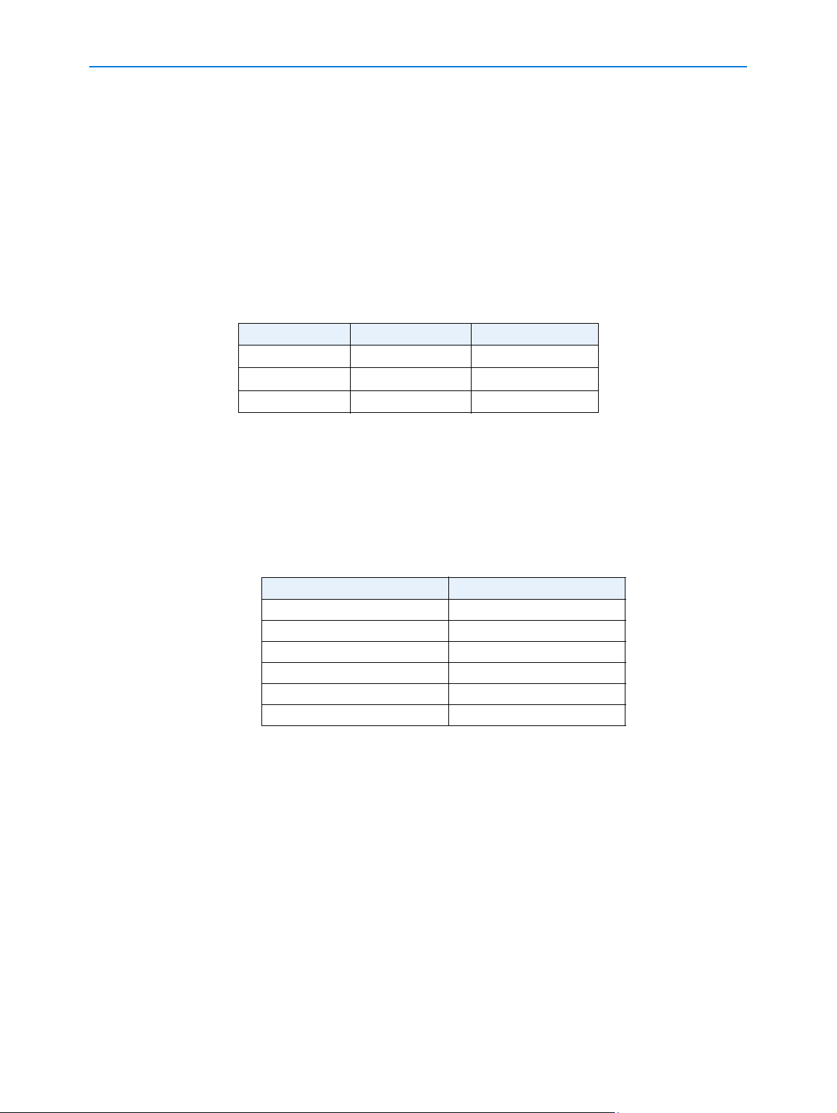
Frame Rates
CIF NTSC PAL
4CIF 30 IPS 25 IPS
2CIF 30 IPS 25 IPS
1CIF 30 IPS 25 IPS
Table 1-1 — Frame Rates
The IP Dome supports a maximum or 30/25 (NTSC/PAL) images per second per video channel at
4 CIF. Actual frame rates may be less due to high motion. Multiple Ethernet connections can limit
the maximum available IPS rate per connection.
Resolutions
The following table displays the resolutions for NTSC and PAL
NTSC PAL
QVGA (320 x 240) QVGA (320 x 240)
1 CIF (352 x 240) 1 CIF (352 x 288)
HVGA (640 x 240) HVGA (640 x 240)
2CIF (704 x 240) 2CIF (704 x 288)
VGA (640 x 480) VGA (640 x 480)
4CIF (704 x 480) 4CIF (704 x 576)
Table 1-2 — Resolutions
Video loss detection
In the event of video loss, an alarm is generated. The alarm is automatically cleared when the
video is restored.
Bandwidth Throttling
When bandwidth throttling is turned on, the camera will attempt to restrict the total bandwidth of all
camera activity to within the specified limits by varying the quality of all video streams. When the
limit is exceeded, for example, by sudden movement in the captured image, the quality of each
codec is reduced by one unit, until the total bandwidth lies below the limit. When the camera
detects that there is sufficient bandwidth available, for example, when the motion stops, it will
increase the video quality by single steps.
1-2 Configuration and User Guide
Page 16

Introduction
This may continue until the total bandwidth reaches 85% of the upper limit, in order to prevent
instability due to continuous throttling. The video quality cannot be increased beyond the original
user configured quality.
The throttling is not carried out on any MJPEG codec if it is only being used for the alarm buffer,
since this is not being streamed over the network.
When bandwidth throttling is turned off, all affected codecs' quality is restored to the original
configured value.
Web Configuration
The IP Dome’s web configuration feature allows you to access the configuration and setting details
for the camera. Depending on user access you can view Live video and control the camera
through PTZ controls as well as changing the settings for the camera environment.
1-3
Page 17

Introduction
1-4 Configuration and User Guide
Page 18
Installation
Detailed installation instructions can be found in the printed Quick Start Guide provided with the IP
Dome.
The installation process is documented using a flowchart in the Quick Installation Guide provided
with the IP Dome and is also found in this manual as the Installation Process.
For detailed installation instructions refer to Install and Detect the IP Dome.
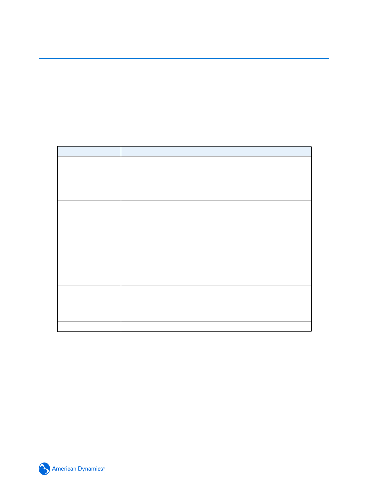
Minimum System Requirements
Component Minimum Requirement
Processor 1 GHz Intel Pentium 4 or Celeron processor or equivalent
processor that supports streaming SIMD extensions (SSE)
Operating System Windows XP Home
Windows XP Professional
Microsoft Vista
RAM 512MB
Monitor 800 × 600 resolution and capable of displaying 16-bit color
Video Card AGP or PCI Express X8 graphics card with 64MB memory and
DirectX 8.0 support
Browser Microsoft Internet Explorer 6.x
Microsoft Internet Explorer 7.x
Microsoft Internet Explorer 8 (IE7Compatibility Mode must be
enabled)
Network Card Ethernet 10/100 NIC
Add-ons QuickTime
ActiveX
JavaScript
Adobe Reader
Miscellaneous Mouse or other pointing device.
Mounts
The IP Dome can be installed using the following mounts:
• ROENDC • RHIUIBM • RHOPN
• RHIU2X2P • RHIUCM • RHOSW
• RHOLW • RHOWCA • RHOWPA
• ADSDICM • ADVESDHRDCLG • ADVESDBASE
Please contact your American Dynamics Sales Representative for more information.
2-1
Page 19
Installation
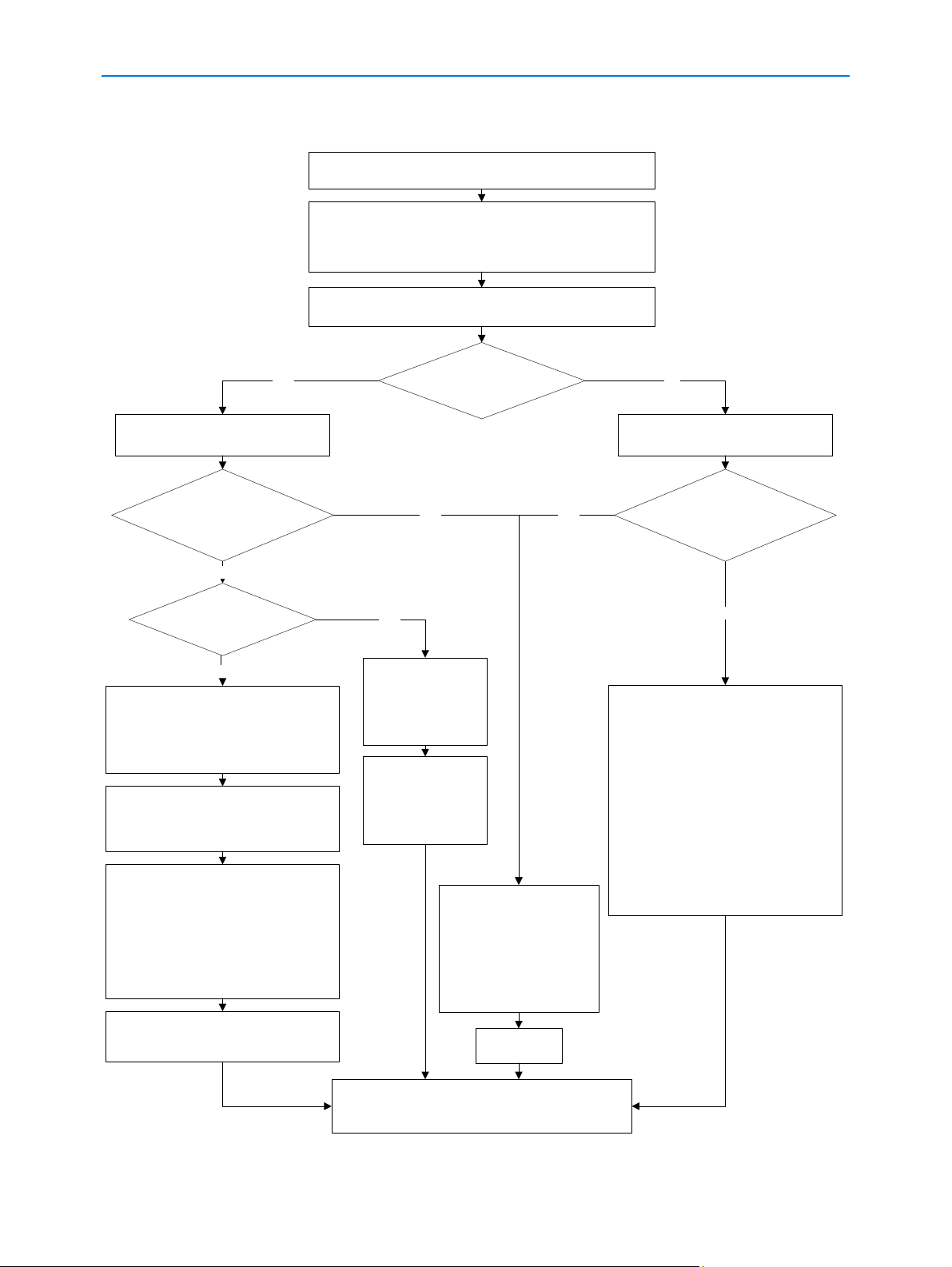
Installation Process
Remove the camera and make note of the serial number and MAC
address located on the side of the box or base of the camera.
Ensure that the IP Dome is connected to the computer or network
which will be used for the configuration and power on.
The camera will begin its initial boot up sequence which will take
approximately 1 to 2 minutes.
The IP Dome will perform three attempts to obtain an IP Address from
YES NO
The camera will automatically be assigned
a Network IP address.
Are you using a proprietary
Network Video Recorder (NVR) to
configure the IP Dome?
NO
Do you have access to the
DHCP Server Logs?
NO
Using a computer which is connected to the
Internet, go to the Apple website
(www.apple.com) and download the Bonjour
for Windows discovery tool from http://
www.apple.com/downloads/macosx/apple/
windows/bonjourforwindows.html.
Follow the directions provided by the
installation file to install Bonjour for Windows
on the computer that will be used to configure
the IP Dome.
Open Microsoft Internet Explorer. To open the
Bonjour toolbar click on the Bonjour icon.
Alternatively you may also enable Bonjour by
selecting View > Explorer Bar > Bonjour. The
Bonjour toolbar will be displayed. The Bonjour
toolbar will list all IP devices found on the
network. The IP Dome is identified as ‘Product
Code - MAC Address’, for example
‘ADVEIPSD22N-00:30:46:01:05:AA'
the DHCP Server.
DHCP Server found and IP
Address allocated?
YES YES
YES
View the DHCP Server
system logs and make
note of the IP address
assigned to the IP
Dome.
Open Microsoft Internet
Explorer and enter the
URL of the IP Dome as
shown in the DHCP
Server logs.
Refer to the NVR manual for
information on how to locate
the IP Dome on the network.
NOTE: The NVR being used to
configure the IP Dome must
have an IP address on the
The IP Dome will be assigned a Static IP
address of 192.168.0.80
Are you using a proprietary
Network Video Recorder (NVR) to
configure the IP Dome?
NO
Open Microsoft Internet Explorer and enter the
URL of the IP Dome as https://192.168.0.80
NOTE: The computer being used to configure
the IP Dome must have an IP address on the
same subnet.
NOTE: Bonjour can also be used to discover
the IP Dome on a static network. Refer to the
Configuration and User guide for more
detailed information.
NOTE: We recommend that the the cameras
IP Address is changed so that conflicts can be
avoided when using the same Static IP
Address.
same subnet.
Double click the required IP Dome from
Bonjour toolbar list to open the Web
Configuration Sign In page.
Refer to the Web Configuration chapter in the Configuration
and User guide for details on how to log in to the IP Dome
and modify the IP Dome configuration.
Select the IP
Dome.
2-2 Configuration and User Guide
Page 20
Install and Detect the IP Dome
The following provides detailed information for installing and accessing the IP Dome.
Installation using DHCP and Bonjour for Windows
The following provides information for installing the IP Dome on your network using the Zeroconf
service discovery protocol and Apple Inc.'s application discovery tool, called Bonjour.
Bonjour, enables automatic discovery of devices on IP networks and is the recommended method
for installation and detection of the IP Dome on the network.
Note
A known limitation of Bonjour for Windows is that it is not always able to maintain an up-to-date list
of IP devices. If Bonjour fails to connect to an IP Dome after the IP Address has been changed,
please restart Microsoft Internet Explorer and re-select the IP Dome in the Bonjour toolbar.
Procedure 2-1 Installing the IP Dome using Bonjour for Windows
1 Using the Quick Start Guide install and connect the IP Dome to the computer or network which
will be used for the configuration and power on.
The camera will begin its initial boot up sequence which will take approximately 1 to 2 minutes.
2 When using a DHCP Server the IP Dome will automatically be assigned a Network IP Address.
Installation
3 Using a computer which is connected to the Internet, go to the Apple website (www.apple.com)
and download the Bonjour for Windows discovery tool from
http://www.apple.com/downloads/macosx/apple/windows/bonjourforwindows.html.
4 Follow the directions provided by the installation file to install Bonjour for Windows on the
computer that will be used to configure the IP Dome.
5 When the installation is complete, open Microsoft Internet Explorer. To open the Bonjour
toolbar click on the Bonjour icon. Alternatively you may also enable Bonjour by selecting View >
Explorer Bar > Bonjour.
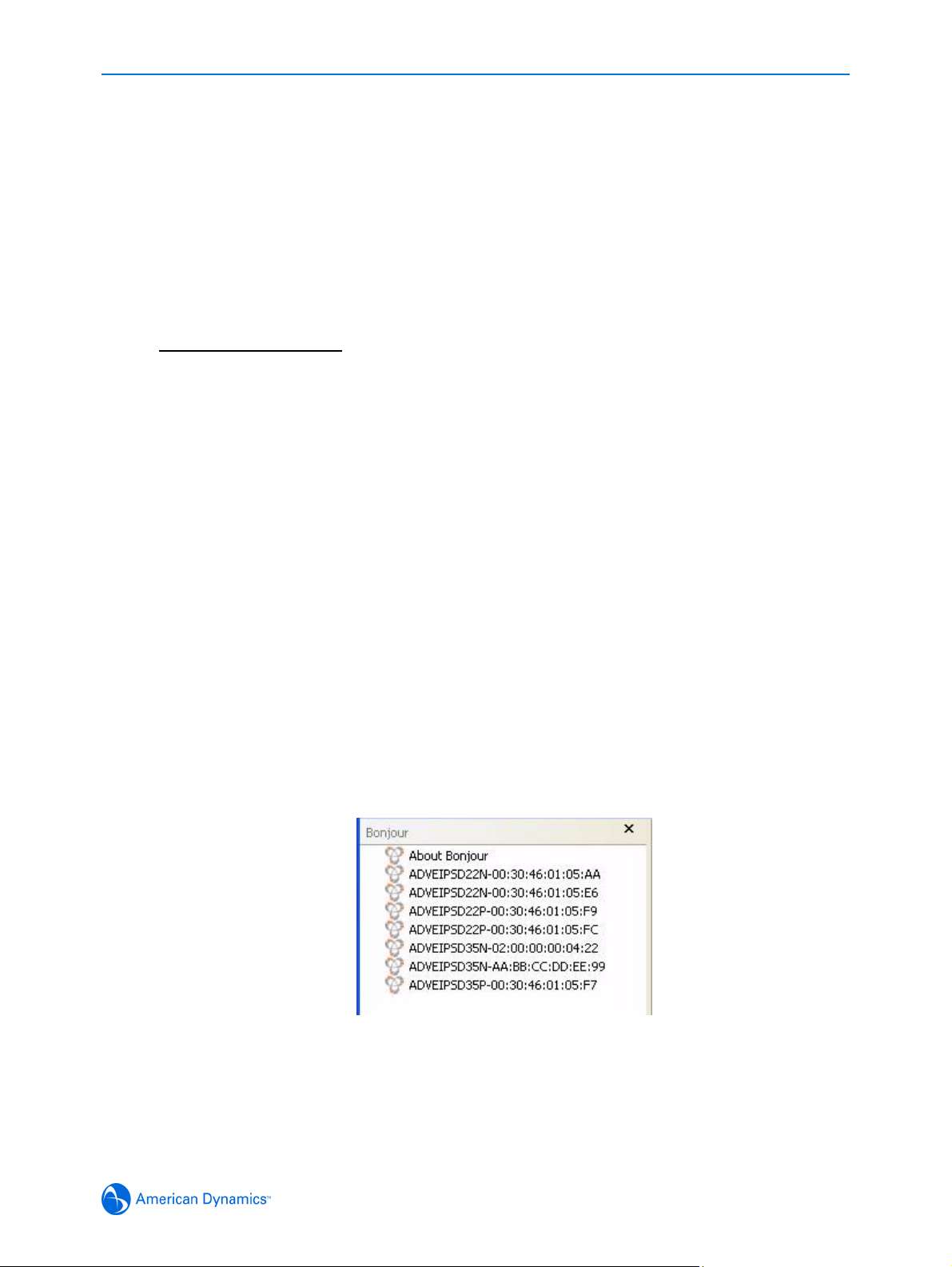
6 The Bonjour toolbar will list all IP devices found on the network. The IP Dome is identified as
‘Product Code - MAC Address’ for example ‘ADVEIPSD22N-00:30:46:01:05:AA’, this can be
seen in
required IP Dome from this list to open the Web Configuration pages.
7 Refer to the Web Configuration chapter for details on how to log in to the IP Dome and modify
the configuration.
Figure 2-1 Bonjour displaying IP devices found on the network. Double click the
Figure 2-1 Bonjour displaying IP devices found on the network
2-3
Page 21

Installation
Procedure 2-2 Installing the IP Dome using DHCP Server Logs
1 Using the Quick Start Guide install and connect the IP Dome to the computer or network which
will be used for the configuration and power on.
The camera will begin its initial boot up sequence which will take approximately 1 to 2 minutes.
2 When using a DHCP Server the IP Dome will automatically be assigned a Network IP Address.
3 View the DHCP Server system logs and make note of the IP address assigned to the IP Dome.
4 Open Microsoft Internet Explorer and enter the URL of the IP Dome as shown in the DHCP
Server log.
Note
The computer being used to configure the IP Dome must have an IP address on the same
subnet.
5 Refer to the Web Configuration chapter for details on how to log in to the IP Dome and modify
the configuration.
Installation without a DCHP Server using a Static IP Address
The following provides information for installing the IP Dome on your network when no DHCP
Server is available. In this situation the IP Dome will be assigned a Static IP Address.
Note
We recommend that once you are logged into the Web Configuration pages you change the Static
IP Address of the camera so that conflicts can be avoided when using the same Static IP Address
to setup additional cameras. Refer to
address of the IP Dome.
IP Address Configuration for information on changing the IP
Procedure 2-3 Installing the IP Dome when a DHCP Server is not available
1 Using the Quick Start Guide install and connect the IP Dome to the computer or network which
will be used for the configuration and power on.
The camera will begin its initial boot up sequence which will take approximately 1 to 2 minutes.
2 The IP Dome will attempt to obtain an IP Address from the DHCP Server. When no DHCP
Server is available the IP Dome will be assigned a Static IP address of 192.168.0.80.
3 Open Microsoft Internet Explorer and enter the URL of the IP Dome as https://192.168.0.80
Note
The computer being used to configure the IP Dome must have an IP address on the same
subnet.
Note
Bonjour for Windows can also be used to discover the IP Dome when using a Static IP
Address. Refer to
at Step 3.
Procedure 2-1 Installing the IP Dome using Bonjour for Windows and begin
4 Refer to the Web Configuration chapter for details on how to log in to the IP Dome and modify
the configuration.
2-4 Configuration and User Guide
Page 22
ActiveX Installation
When using Internet Explorer to access the IP Dome the browser may need to download and
install selected ActixeX plug-ins.
The web browser uses the following ActiveX controls:
• Sensormatic Electronics Corporation - to display live video and enable privacy zones.
• Apple Quick Time - to enable audio.
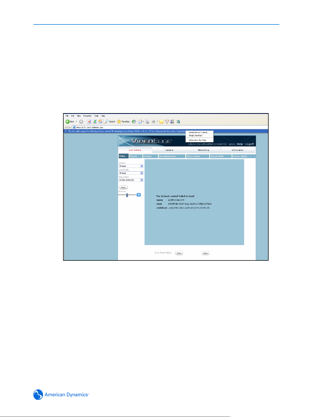
Depending on your browser security settings you may see a message displayed in the information
bar prompting you to proceed with an automatic installation. The highlighted information bar can
be seen in Figure 2-2 Install ActiveX Control.
Installation
Figure 2-2 Install ActiveX Control
Right-click the information bar and select “Install ActiveX Control” the ActiveX plug-in will be
installed.
2-5
Page 23

Installation
2-6 Configuration and User Guide
Page 24

Web Configuration
This section details how to configure the IP Dome using the built-in Web Configuration feature.
Depending on user access you can view Live video and control the camera through PTZ controls
as well as changing the settings for the camera environment.
Some items supplement similar features that may be available through your controller.
Note
To view the Live Web Video pane the latest versions of JavaScript, ActiveX and QuickTime must
be installed and enabled on the computer running the browser session.
Note
Adobe Reader must be installed to view the online help.
Note
Web Configuration sessions timeout after a period of inactivity.
Note
Only users with administrative rights can access all the areas of the Web Configuration pages.
3-1
Page 25
Web Configuration
Log in to the IP Dome
Procedure 3-4 Logging in to the IP Dome
1 Refer to the Installation chapter for details on how to connect to the IP Dome on your network
or computer.
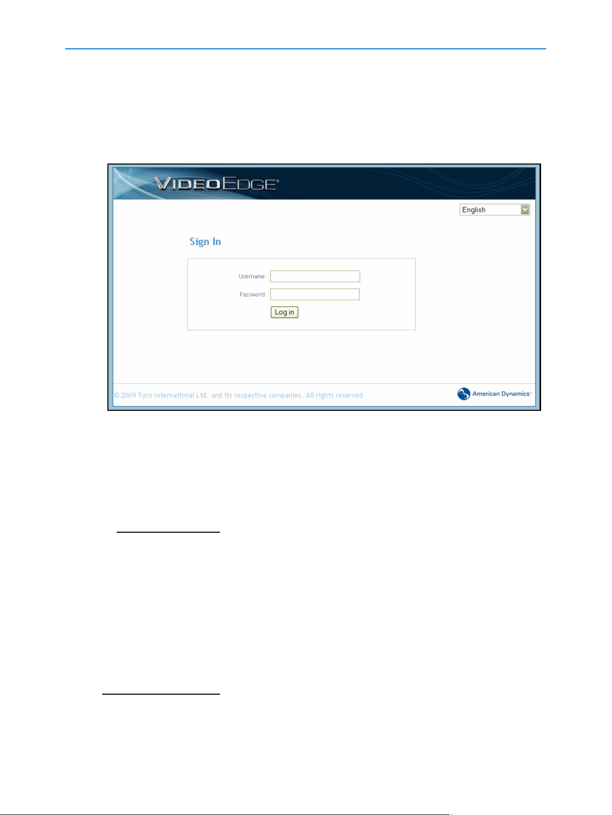
2 When the IP Dome is selected Figure 3-1 the IP Dome Sign In page will be displayed.
Figure 3-1 Sign in page
3 Select your preferred language from the drop-down menu in the right hand corner. The sign in
page will be updated to display the selected language.
4 Enter the appropriate user name and password, then select the Log in button.
Depending on the access rights of the user, there may be specific camera functions that are
unavailable. All camera functions are described on the following pages.
Note
The default username is admin and the default password is admin. To maintain security we
recommend that the password on the admin account is changed, refer to
Changing an existing password for further information.
Procedure 7-60
User Accounts
There are three types of user account that can be used to access the camera functions these are
administrator, recorder and user.
• Refer to Procedure 6-36 Add a User for information on creating user accounts.
• Refer to Appendix 10: User Account Privileges which provides an overview of user accounts.
Note
The default user accounts for ‘admin’ and ‘recorder’ cannot be deleted. To maintain security we
recommend that the password on these accounts are changed, refer to
an existing password for further information.
Procedure 7-60 Changing
3-2 Configuration and User Guide
Page 26
Web Configuration
Administrator
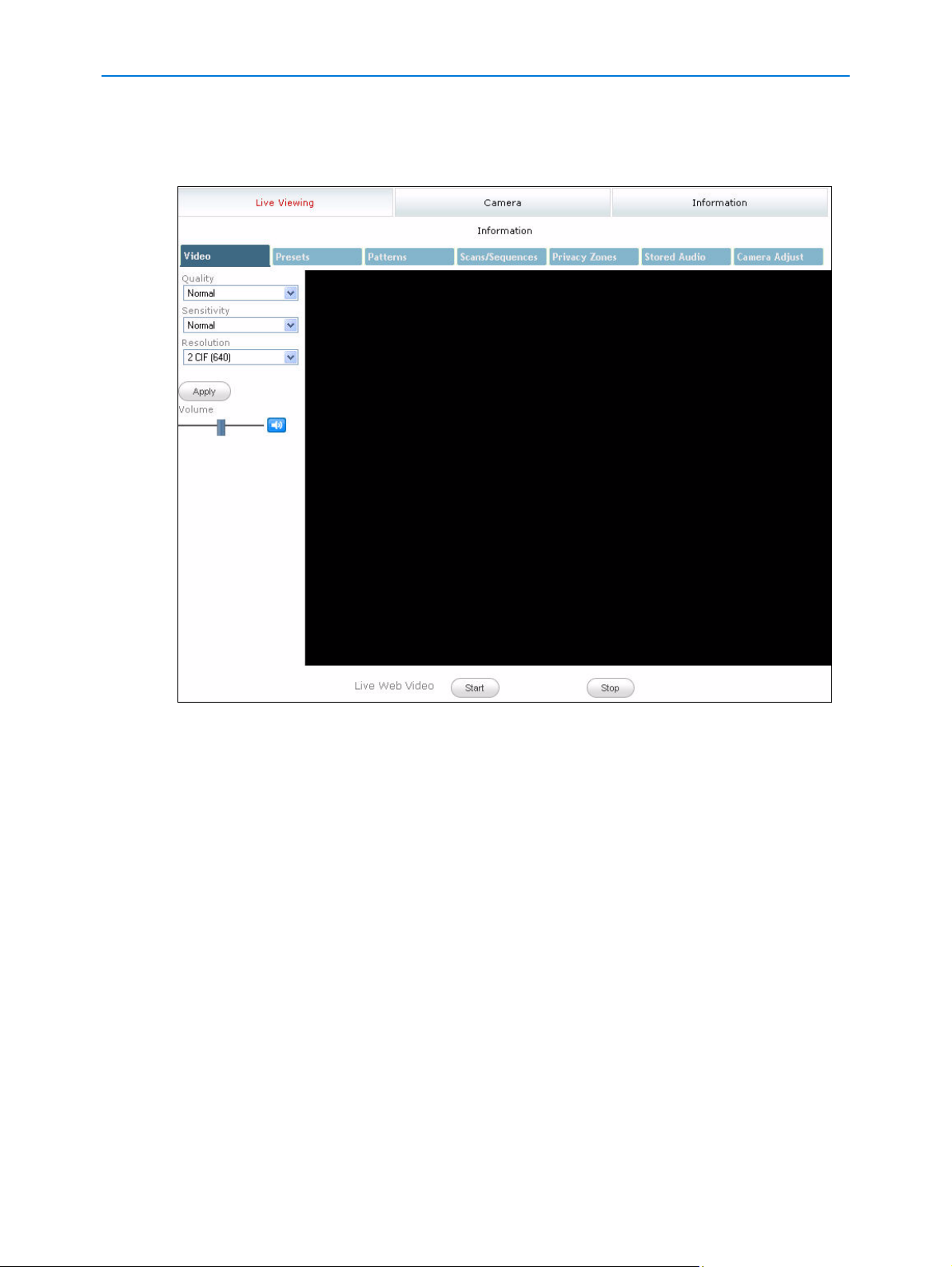
When an Administrator has logged in Figure 3-2 the Live Viewing screen will be displayed. An
‘admin’ account has full access to all of the cameras functions and information. The default
Figure 3-2 Live Viewing Screen
The options available to the Administrator are:
• Live Viewing - allows access to live video and camera controls. It also allows the
configuration of video, presets, patterns, scans/sequences, privacy zones, audio and camera
settings.
• Camera - allows configuration of the PTZ functionality, overlay settings, areas within the field
of view, alarms, sequences, scheduled tasks, video settings and further audio.
• Networking - allows configuration of camera date and time, TCP/IP, user rights, SMTP, FTP,
firewall, general maintenance and advanced settings.
• Information - provides information on the camera model, PTZ statistics, environmental
readings, system log, boot log, current faults and provides a password changing function.
• Help - opens a window with help information.
• Logoff - exit the application.
3-3
Page 27
Web Configuration
Recorder
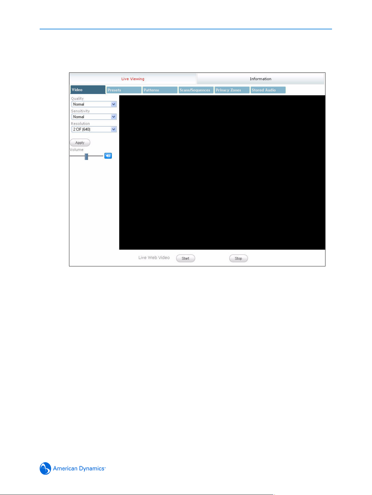
When a Recorder user has logged inFigure 3-3 the Live Viewing screen will be displayed. A
‘recorder’ account has limited access to the camera functions and information.
Figure 3-3 Live Viewing Logged in as Recorder
The options available to the Recorder are:
• Live Viewing - allows access to live video and camera controls. It also allows the
configuration of video, presets, patterns, scans/sequences, privacy zones, audio and camera
settings.
• Camera - allows configuration of the PTZ functionality and sequences.
• Information - provides information on the camera model, PTZ statistics, environmental
readings, current faults and provides a password changing function.
• Help - opens a window with help information.
• Logoff - exit the application.
3-4 Configuration and User Guide
Page 28
Web Configuration
User
When a User user has logged in Figure 3-4 the Live Viewing screen will be displayed. A ‘user’
account has limited access to the camera functions and information.
Figure 3-4 Live Viewing Logged in as User
The options available to the user are:
• Live Viewing - allows access to live video and camera controls. Also allows the selection of
presets, patterns, scans/sequences, audio and privacy zones.
• Information - provides data on the camera model and provides a password changing
function.
• Help - opens a window with help information.
• Logoff - exit the application.
3-5
Page 29

Web Configuration
Checking Camera Feed using the Live Viewing function
The Live Viewing page provides a simple way to test the video inputs from the IP Dome. This Live
Viewing page is not intended to be the primary way of viewing the video on the IP Dome; this
should be performed using the Network Video Recording device.
The Live Web Video is accessible to any authorized user.
Procedure 3-5 Starting the Live Web Video feed
Note
To view the Live Web Video pane the latest versions of JavaScript, Active X and QuickTime must
be installed and enabled on the computer running the browser session.
1 Log in to the IP Dome using an appropriate user name and password, for more details refer to
Procedure 3-4 Logging in to the IP Dome. Figure 3-2 the Live Viewing page is displayed.
2 Select the Live Web Video Start and Stop button, located to start and stop the live video feed.
The live web Video pane will display the video feed.
Note
Displaying live video may affect other video streams.
Procedure 3-6 Checking camera feed using the Live Viewing function
Note
Changing the Quality, Sensitivity, Resolution or Volume settings only affects what is being
displayed on the Live Viewing page. Changing these settings does not affect the video being sent
by the IP Dome to the Network Video Recording device.
Note
When Apply is selected it may take a few seconds to update the Live Web Video feed.
1 Log in to the IP Dome using an appropriate user name and password, refer to Procedure 3-4
Logging in to the IP Dome. Figure 3-2 the Live Viewing page is displayed.
2 Follow Procedure 3-5 Starting the Live Web Video feed.
3 Select the Quality setting from the drop-down menu and select the Apply button.
• Extended
• Normal
• Super
The default Quality is set to Normal.
4 Select the Sensitivity from the drop-down menu and select the Apply button.
• Normal
•High
The default Sensitivity is set to Normal.
5 Select the Resolution from the drop-down menu and select the Apply button.
•1CIF (320)
•1CIF (352)
•2CIF (640)
3-6 Configuration and User Guide
Page 30

Web Configuration
•2CIF (704)
•4CIF (640)
•4CIF (704)
The default Resolution is set to 2CIF (640).
6 To adjust the volume use the slider, or the mute button. The slider bar can be moved left or right
using the mouse or for fine adjustments using the left and right arrow keys on the PC keyboard.
The default volume is set to 50 and the mute button will be enabled.
7 Select a different tab to exit the screen, or Logoff to exit the application.
Controlling dome cameras on the Live Viewing page
The IP Dome camera may be controlled using the on-screen controls in the live web Video pane.
Dome Camera Controls
The following information details the various controls that are available for the on-screen dome
control.
Note
It is possible for two users to access Live Viewing at the same time however only one user may
control the camera at any time. If a new user opens a camera control session on the same camera
using a different browser the original user will lose their camera control session.
The dome control symbol appears in the lower right hand corner.
3-7
Page 31

Web Configuration
Procedure 3-7 Controlling the camera via the Live Web Video pane
Note
Scheduled tasks, alarms and manual dome camera control will always begin when they are
selected or scheduled to start. None of these camera actions have a priority over the other. If a
camera action is in progress and a new action is selected or activated the previous action will stop
before the new action is started.
1 Follow Procedure 3-5 Starting the Live Web Video feed.
2 Select Dome Control in the Live Web Video pane.
3 Select the camera control item on the overlay to activate the control.
Pan/Tilt control
Zoom
Flips the camera 180°
Close the dome control overlay
(Exit)
Opens the pattern menu
Iris
.
Focus
Zoom
In
Out
Iris
Open
Auto Iris (on cameras with this feature)
Close
Presets
Open the Preset Menu
Opens the preset menu
Focus
Near
Far
Pan/Tilt Movement
Pan/Tilt (outer rim)
Patterns
Open the Pattern Menu
4 Select Exit to close the camera control overlay.
3-8 Configuration and User Guide
Page 32

Web Configuration
Controlling the Pan-Tilt Control via Mouse
Controlling the camera using the mouse will allow you to move slowly which will provide maximum
accuracy.
Procedure 3-8 Controlling Pan and Tilt via a mouse using the Live Web Video pane
1 Follow Procedure 3-5 Starting the Live Web Video feed.
2 Select Dome Control in the live web Video pane. The camera control overlay will be
displayed.
3 Move the cursor over the center of the video pane. The Cursor Origin Mark appears as
shown in Figure 3-5.
Figure 3-5 Live image with Cursor Origin Mark and Direction cursor displayed
4 Click and drag the cursor to set the direction and speed, then release.
• The camera’s movement speed increases proportionally with the arrow’s distance from the
cursor origin mark.
• The camera’s direction is relative to cursor origin mark.
5 Select Exit to close the camera control overlay.
Zoom via Mouse Scroll Wheel
Controlling the zoom function using the mouse
Procedure 3-9 Zooming via the mouse scroll wheel using the Live Web Video pane
1 Follow Procedure 3-5 Starting the Live Web Video feed.
2 Use Procedure 3-7 Controlling the camera via the Live Web Video pane or/and Procedure 3-8
Controlling Pan and Tilt via a mouse using the Live Web Video pane to locate the area you
would like to zoom.
3 Point the camera at a target.
4 Scroll the mouse wheel upwards (zoom in) and downwards (zoom out).
3-9
Page 33

Web Configuration
5 Select Exit to close the camera control overlay.
Procedure 3-10 Selecting a Pattern via the Camera Control Overlay
Note
It is also possible to select a pattern using the Pattern menu, refer to Procedure 4-21 Selecting a
Pattern for more information.
1 Follow Procedure 3-5 Starting the Live Web Video feed.
2 Select Dome Control in the Live Web Video pane. The camera control overlay will be
displayed.
3 Select Pattern in the camera control overlay to open the pattern menu. The pattern menu
will be displayed:
4 Select a pattern number from the drop-down menu.
5 Select to run the pattern.
The pattern will run continuously until interrupted by a camera command, pattern, scan or
alarm.
6 Select Exit to close the pattern menu.
7 Select Exit to close the camera control overlay.
Procedure 3-11 Add a Pattern via the Camera Control Overlay
Note
For best results we recommend that you use the Pattern menu to define a new pattern, refer to
Procedure 4-20 Adding a Pattern for more information.
1 Follow Procedure 3-5 Starting the Live Web Video feed.
2 Select Dome Control in the Live Web Video pane. The camera control overlay will be
displayed.
Click the dome icon, use the camera overlay controls to locate the pattern starting point. See
Procedure 3-7 Controlling the camera via the Live Web Video pane and Procedure 3-8
Controlling Pan and Tilt via a mouse using the Live Web Video pane for further details.
3 Select Pattern in the camera control overlay to open the pattern menu. The pattern menu
will be displayed:
3-10 Configuration and User Guide
Page 34

Web Configuration
4 Select a pattern slot number from the drop-down menu, the new pattern will be saved to this
slot number. Select Define Pattern
the pattern definition menu will be displayed:
Note
If the selected pattern slot number has been assigned to a pattern it will be replaced without
warning. This also applies to any pattern that is associated with a Home Position, Alarm Action
or Scheduled task. The original pattern will be replaced by the new pattern.
Note
The apple peel pattern as a default will be saved to pattern slot numbers 1 and 16. If these
pattern slot numbers are selected when defining a pattern the apple peel pattern will be
replaced by the new pattern. To restore the apple peel pattern you must follow
Procedure 6-49
Restore Factory Defaults.
5 Select Start to begin programming the pattern. Use the camera control overlay to define
the pattern’s behavior.
Note
A pattern can contain a maximum of 97 steps with an unlimited duration.
Note
A diagonal pan or tilt move will use 4 steps.
6 The white progress bar provides a visual representation of the number of steps remaining in
the pattern. As steps are added to the pattern this progress bar will decrease.
When the progress bar reaches the left side, no more steps will be saved for the pattern.
7 Select Stop . to end the pattern recording. The Replace Pattern dialog will appear prompting
you to confirm that the pattern should be saved. Select Yes to save or No to cancel.
The camera settings you have configured will be used for the pattern. Refresh the page.
8 Select Exit to close the pattern’s definition menu.
9 To test the new pattern, select the pattern number from the drop-down menu and select .
The pattern will run continuously until interrupted by a camera command, pattern, scan or
alarm.
10 Select Exit to close the Pattern menu.
11 Select Exit to close the Primary Camera Control menu.
Procedure 3-12 Selecting a Preset via the Camera Control Overlay
Note
It is also possible to select a preset using the Preset menu, refer to Procedure 4-16 Selecting a
Preset for more information.
1 Follow Procedure 3-5 Starting the Live Web Video feed.
3-11
Page 35

Web Configuration
2 Select Dome Control in the Live Web Video pane. The camera control overlay will be
displayed.
3 Select Preset in the camera control overlay to open the preset menu. The preset menu
will be displayed:
4 Select a preset slot number from the drop-down menu.
5 Select to run the preset.
The preset will run continuously until interrupted by a camera command, pattern, scan or alarm.
6 Select Exit to close the preset menu.
7 Select Exit to close the camera control overlay.
Procedure 3-13 Defining a Preset via the Camera Control Overlay
Note
For best results we recommend that you use the Preset menu to add a new preset, refer to
Procedure 4-15 Adding a Preset for more information.
1 Follow Procedure 3-5 Starting the Live Web Video feed.
2 Select Dome Control in the Live Web Video pane. The camera control overlay will be
displayed.
Click the dome icon, use the camera overlay controls to locate the preset scene. See
Procedure 3-7 Controlling the camera via the Live Web Video pane and Procedure 3-8
Controlling Pan and Tilt via a mouse using the Live Web Video pane for further details.
3 Select in the camera control overlay to open the preset menu. The preset menu will be
displayed:
4 Select a preset slot number from the drop-down menu, the new preset will be saved to this slot
number.
Note
If the selected preset slot number has been assigned to a preset it will be replaced without
warning. This also applies to any preset that is associated with a Sequence, Home Position,
Alarm Action or Scheduled task. The original preset will be replaced by the new preset.
5 Select Define Preset the Replace Preset dialog will appear prompting you to confirm that
the preset should be saved. Select Yes to save or No to cancel.
The camera settings you have configured on the camera will be used for the preset. Refresh
the page.
6 To test the new preset, select the preset number from the drop-down menu and select .
The preset will run continuously until interrupted by a camera command, pattern, scan or alarm.
7 Select to close the preset menu.
8 Select to close the camera control overlay.
3-12 Configuration and User Guide
Page 36

Live Viewing Menu
Video
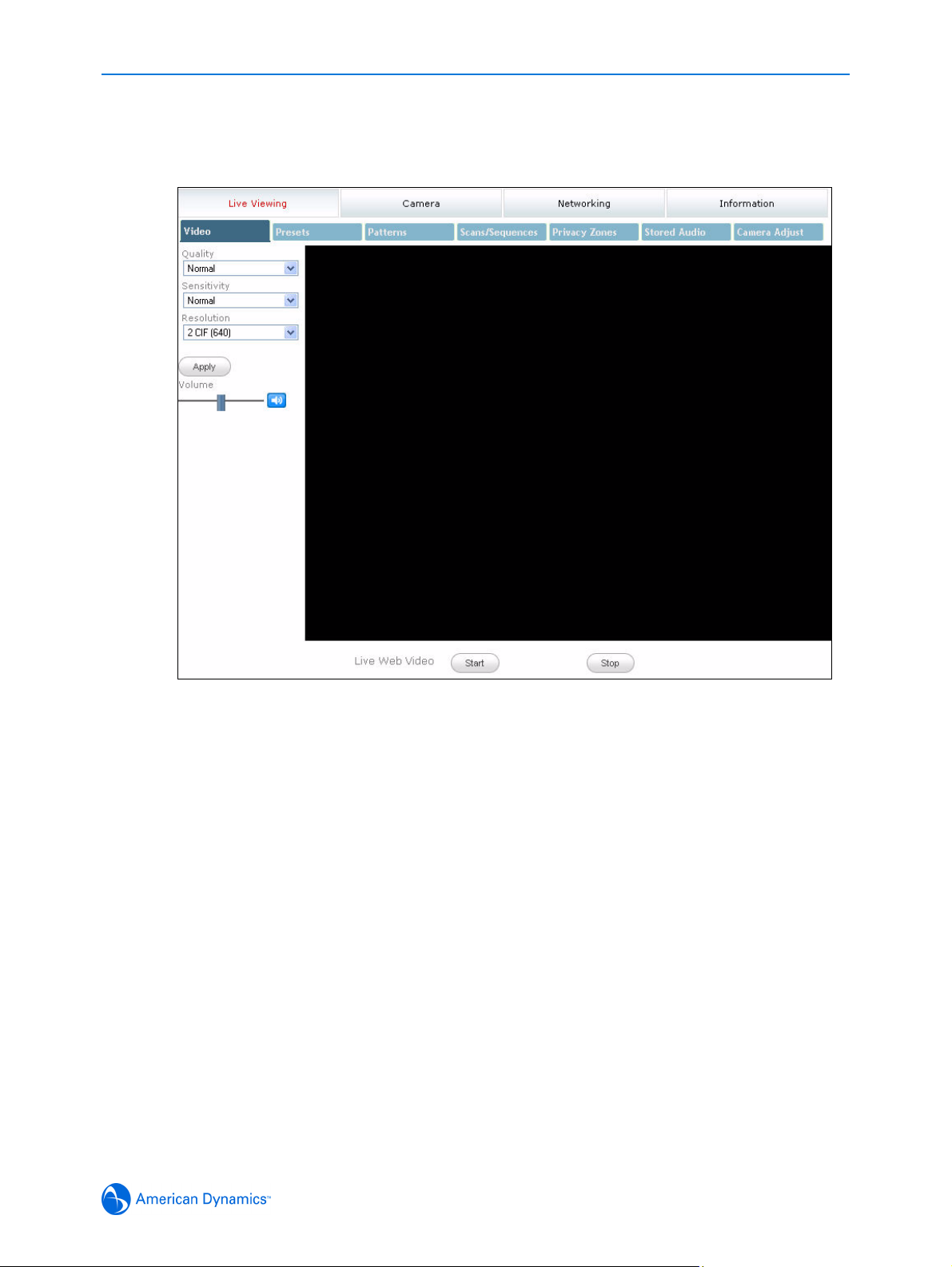
When Video is selected from the Live Viewing menu and Live Web Video has been started, (refer
to Procedure 3-5 Starting the Live Web Video feed) Figure 4-6 the Video screen will be displayed.
Figure 4-6 Video screen
Procedure 4-14 Configuring the Video settings
Note
Changing the Quality, Sensitivity, Resolution or Volume settings only affects what is being
displayed on the Live Viewing page. Changing these settings does not affect the video being sent
by the Network Video Recording device.
Note
When Apply is selected it may take a few seconds to update the Live Web Video feed.
1 Log in to the IP Dome using an appropriate user name and password, for more details refer to
Procedure 3-4 Logging in to the IP Dome.
2 Select Video from the Live Viewing menu. Figure 4-6 the Video screen will be displayed.
3 Follow Procedure 3-5 Starting the Live Web Video feed.
4 Select the Quality setting from the drop-down menu and select the Apply button.
• Extended
4-1
Page 37

Live Viewing Menu
• Normal
• Super
The default Quality is set to Normal.
5 Select the Sensitivity from the drop-down menu and select the Apply button.
• Normal
•High
The default Sensitivity is set to Normal.
6 Select the Resolution from the drop-down menu and select the Apply button.
When using PAL, the resolution options are:
• QVGA (320 x 240)
• 1 CIF (352 x 288)
• HVGA (640 x 240)
• 2CIF (704 x 288)
• VGA (640 x 480)
• 4CIF (704 x 576)
The default PAL resolution is set to 2CIF (704 x 288).
When using NTSC, the resolution options are:
• QVGA (320 x 240)
• 1 CIF (352 x 240)
• HVGA (640 x 240)
• 2CIF (704 x 240)
• VGA (640 x 480)
• 4CIF (704 x 480)
The default NTSC resolution is set to 2CIF (704 x 240).
7 To adjust the volume use the slider, or the mute button. The slider bar can be moved left or right
using the mouse or for fine adjustments using the left and right arrow keys on the PC keyboard.
The default volume is set to 50 and the mute button will be enabled.
8 Select a different tab to exit the screen, or Logoff to exit the application.
4-2 Configuration and User Guide
Page 38

Live Viewing Menu
Presets
A Preset is a pre-positioned camera scene that you program for cameras installed with pan/tilt and
motorized lens capability. Up to 96 presets can be programmed from the Live Viewing screen.
Procedure 4-15 Adding a Preset
Note
This procedure is the recommended method for adding a new preset, however It is also possible
to add a preset using the camera overlay control, refer to
Camera Control Overlay.
1 Follow Procedure 3-5 Starting the Live Web Video feed.
2 Make the necessary camera adjustments.
The following controls can be modified and saved as part of the preset. The pan, tilt and zoom
can be accessed using Procedure 3-7 Controlling the camera via the Live Web Video pane.
The remaining controls can be accessed via the Camera Adjust menu.
• Pan, Tilt and Zoom.
• Focus Mode and Iris Mode
Procedure 3-13 Defining a Preset via the
Note
Additional controls can also be saved as part of the preset. Complete this procedure then refer
to
Procedure 4-17 Editing a Preset to add the additional controls.
3 Select Presets from the Live Viewing menu.
4-3
Page 39

Live Viewing Menu
4 Select Add Preset from the Presets menu. Figure 4-7 the add Preset screen will be displayed.
Figure 4-7 Add Preset screen
5 Enter the Preset Name in the text box.
6 Select a Preset Slot Number from the drop-down menu.
A free preset slot number will have the slot number displayed, for example, ‘12)’. If the slot
number has been pre-defined, the slot number and preset name will be displayed, for example,
‘10) Main Entrance’.
If you select a preset slot number that has been pre-defined will be prompted to overwrite the
existing preset. Select OK to continue or Cancel to select an alternative preset slot number.
7 Select the Add button. The camera settings you have configured on the camera will be used
for the preset.
The preset will now appear on the Select Preset and Delete Preset drop-down menus.
Procedure 4-16 Selecting a Preset
Note
It is also possible to select a preset using the camera overlay control, refer to Procedure 3-12
Selecting a Preset via the Camera Control Overlay.
1 Follow Procedure 3-5 Starting the Live Web Video feed.
2 Select Presets from the Live Viewing menu.
4-4 Configuration and User Guide
Page 40

Live Viewing Menu
3 Choose Select Preset from the Presets menu. Figure 4-8 the Select Preset section will be
displayed.
Figure 4-8 Select Preset
4 Select the pre-defined preset from the drop-down menu.
5 Select the Goto button to activate the preset. The Live Web Video pane will update to display
the selected preset.
The preset will run continuously until interrupted by a camera command, pattern, scan or alarm.
Procedure 4-17 Editing a Preset
1 Select Presets from the Live Viewing menu.
2 Choose Select Preset from the Presets menu. Figure 4-8 the Select Preset section will be
displayed.
3 Select a pre-defined preset from the drop-down menu. Select the Goto button to activate the
preset.
4 Make the necessary camera adjustments.
The following controls can be modified and saved as part of the preset. The pan, tilt and zoom
can be accessed using Procedure 3-7 Controlling the camera via the Live Web Video pane.
The remaining controls can be accessed via the Camera Adjust menu.
• Pan, Tilt and Zoom
• Focus Mode and Iris Mode
• Electronic Image Stabilization and Wide Dynamic Range
• White Balance
• Infrared Mode and Day Night Mode
• Shutter Limit and Gain
• Brightness, Contrast, Hue and Saturation
Select Presets from the Live Viewing menu when you have finished the camera adjustments.
5 Select the Set button when you have finished any modifications. You will be prompted to
confirm the update.Select the OK button to confirm or the Cancel button to stop the update.
The camera settings you have configured on the camera will be used for the preset.
4-5
Page 41

Live Viewing Menu
Using Preset as Home Position
The home position runs after a designated period of dome inactivity. Select a home position if you
want to keep a specific area under surveillance whenever the dome is not moving.
Follow Procedure 5-6 Display Current Home Position to change the return time for the home
position.
Procedure 4-18 Using a Preset as a Home Position
1 Select Presets from the Live Viewing menu.
2 Choose Select Preset from the Presets menu. Figure 4-8 the Select Preset section will be
displayed.
3 Select a pre-defined preset from the drop-down menu.
4 Select the Use as Home button to set the selected preset as the camera home position.
Procedure 4-19 Delete a Preset
1 Select Presets from the Live Viewing menu.
2 Select Delete Preset from the Presets menu. Figure 4-8 the Delete Preset section will be
displayed.
Figure 4-9 Delete Preset
3 Select a pre-defined preset from the drop-down menu.
Note
You cannot delete a preset while it is associated with another camera function. To remove the
preset refer to the associated camera function,
Position, Configuring Alarm Actions and Editing a Scheduled Task.
4 Select the Delete button. You will be prompted to confirm the deletion. Select the OK button to
confirm or the Cancel button to stop the deletion.
4-6 Configuration and User Guide
Editing a Sequence, Clear the Current Home
Page 42

Live Viewing Menu
Patterns
A pattern is a series of pan, tilt, zoom and focus movements which can be saved to the dome. A
maximum of 16 patterns can be programmed for the IP Dome each containing up to 97 steps with
an unlimited duration.
Procedure 4-20 Adding a Pattern
Note
This procedure is the recommended method for adding a new pattern, however It is also possible
to add a pattern using the camera overlay control, refer to
Camera Control Overlay.
1 Follow Procedure 3-5 Starting the Live Web Video feed.
Click the dome icon, use the camera overlay controls to locate the pattern starting point. See
Procedure 3-7 Controlling the camera via the Live Web Video pane and Procedure 3-8
Controlling Pan and Tilt via a mouse using the Live Web Video pane for further details.
2 Select Patterns from the Live Viewing menu.
3 Select Add Pattern from the Patterns menu. Figure 4-10 the Add Pattern screen will be
displayed.
Procedure 3-11 Add a Pattern via the
Figure 4-10 Add Pattern screen
4-7
Page 43

Live Viewing Menu
4 Enter the Pattern Name in the text box and select the Define button. The Add Pattern section
will update with an Add and Cancel button. See
Figure 4-11 Add Pattern with active Add and Cancel button
Figure 4-11.
Use the camera overlay controls to configure the required pattern settings. See Procedure 3-7
Controlling the camera via the Live Web Video pane and Procedure 3-8 Controlling Pan and
Tilt via a mouse using the Live Web Video pane for further details.
Note
A pattern can contain a maximum of 97 steps with an unlimited duration.
Note
A diagonal pan or tilt move will use 4 steps.
The following controls can also be modified and saved as part of the pattern. These can be
accessed via the Camera Adjust menu.
• Focus Mode
• Iris Mode
4-8 Configuration and User Guide
Page 44

Live Viewing Menu
5 The white progress bar provides a visual representation of the number of steps remaining in
the pattern, this can be seen in
Figure 4-12 Add Pattern with progress bar displayed. As steps
are added to the pattern this progress bar will decrease.
Figure 4-12 Add Pattern with progress bar displayed
When the progress bar reaches the left side, no more steps will be saved for the pattern.
6 Select the Add button when you have finished. The camera settings you have configured will
be used for the pattern. Select the Cancel button to cancel the configuration.
The pattern will now appear on the Select Pattern and Delete Pattern drop-down menus.
Procedure 4-21 Selecting a Pattern
Note
It is also possible to select a pattern using the camera overlay control, refer to Procedure 3-10
Selecting a Pattern via the Camera Control Overlay.
1 Select Patterns from the Live Viewing menu.
4-9
Page 45

Live Viewing Menu
2 Choose Select Pattern from the Patterns menu. Figure 4-8 the Select Pattern section will be
displayed.
Figure 4-13 Select Pattern
3 Select the pre-defined pattern from the drop-down menu.
Note
Apple Peel is a predefined pattern stored on the camera by default. This pattern slowly tilts and
rotates the camera through 360 degrees starting at the ceiling line. When the IP Dome reaches
the lowest tilt point it will perform three revolutions. The IP Dome will then follow the tilt and
rotate pattern to return to the starting point. The pattern will run continuously until interrupted by
a camera command, preset, scan or alarm.
4 Select the Start button to activate the pattern. The Live Web Video pane will update to display
the selected pattern.
The pattern will run continuously until interrupted by a camera command, preset, scan or alarm.
Using Pattern as Home Position
The home position runs after a designated period of dome inactivity. Select a home position if you
want to keep a specific area under surveillance whenever the dome is not moving.
Follow Procedure 5-6 Display Current Home Position to change the return time for the home
position.
Procedure 4-22 Using a Pattern as a Home Position
1 Select Patterns from the Live Viewing menu.
2 Choose Select Pattern from the Patterns menu. Figure 4-8 the Select Pattern section will be
displayed.
3 Select a pre-defined pattern from the drop-down menu.
4 Select the Use as Home button to set the selected pattern as the camera home position.
Procedure 4-23 Delete a Pattern
1 Select Patterns from the Live Viewing menu.
4-10 Configuration and User Guide
Page 46

Live Viewing Menu
2 Select Delete Pattern from the Patterns menu button. Figure 4-14 the Delete Pattern section
will be displayed.
Figure 4-14 Delete Pattern
3 Select a pre-defined pattern from the drop-down menu.
Note
You cannot delete a pattern while it is associated with another camera function. To remove the
pattern refer to the associated camera function,
Clear the Current Home Position, Configuring
Alarm Actions and Editing a Scheduled Task.
4 Select the Delete button. You will be prompted to confirm the deletion. Select the OK button to
confirm or the Cancel button to stop the deletion.
4-11
Page 47

Live Viewing Menu
Scans/Sequences
The following section provides information on configuring Scans and Sequences for the IP Dome.
Scans
A scan allows you to program left and right scan limits to automate your surveillance activities.
Once these scan limits are programmed you can choose to run a smooth scan, stepped scan, or
random scan. When active, the scan repeats until interrupted by a camera command, preset,
pattern or alarm.
Procedure 4-24 Setting Scan Limits
1 Select Scans/Sequences from the Live Viewing menu.
2 Select Scan Limits from the Scans/Sequences menu. Figure 4-8 the Scan Limits section will
be displayed.
Figure 4-15 Scan Limits section
3 Click the dome icon on the Live Web Video pane and use the camera controls to locate the left
scan limit. See
details. Select the Set Left button to set the displayed position as the left limit.
4 Use the camera controls to locate the right scan limit. See Procedure 3-7 Controlling the
camera via the Live Web Video pane for further details. Select the Set Right button to set the
displayed position as the right limit.
5 Follow Procedure 4-25 Activating a Scan. The Live Web Video pane will run the scan within the
selected scan limits.
Procedure 3-7 Controlling the camera via the Live Web Video pane for further
Procedure 4-25 Activating a Scan
1 Follow Procedure 4-24 Setting Scan Limits before starting a scan.
2 Select Scans/Sequences from the Live Viewing menu.
4-12 Configuration and User Guide
Page 48

Live Viewing Menu
3 Choose Select Scan from the Scans/Sequences menu. Figure 4-16 the Select Scan screen
will be displayed.
Figure 4-16 Select Scan screen
4 Select the type of scan to perform from the drop-down menu:
• smooth - slowly pans between the left and right scan limits, starting at the left scan limit.
When the right scan limit is reached, the scan reverses.
• stepped - pans slowly, pausing briefly every 10° between the left and right scan limits. Once
the right scan limit is reached, the scan reverses.
• random - pans randomly between the left and right scan limits. For example, the scan may
start at 10°, then pan right 40° and pause, pan right 20° and pause, pan left 30° and pause,
and pan right until it reaches the right scan limit.
5 Select the Start button to activate the scan. The Live Web Video pane will update and display
the selected scan.
The scan will run continuously until interrupted by a camera command, pattern, preset or alarm.
Using Scan as Home Position
The home position runs after a designated period of dome inactivity. Select a home position if you
want to keep a specific area under surveillance whenever the dome is not moving.
Follow Procedure 5-6 Display Current Home Position to change the return time for the home
position.
Procedure 4-26 Using a Scan as a Home Position
1 Select Scans/Sequences from the Live Viewing menu.
4-13
Page 49

Live Viewing Menu
2 Choose Select Scan from the Scans/Sequences menu. Figure 4-16 the Select Scan screen
will be displayed.
3 Select the type of scan to perform from the drop-down menu.
4 Select the Use as Home button to set the selected scan as the camera home position.
Sequences
A Sequence is a sequential display of multiple camera Presets. Sequences provide a methodical
and effective way to monitor multiple areas of interest by switching to different Presets
automatically.
Sequences are created by identifying Preset views to include in the Sequence and specifying a
dwell time that controls how long each Preset remains on-screen before switching to another
Preset. Up to 16 Sequences can be created, each with 16 steps (Presets).
Refer to Procedure 5-18 Add a Sequence for information on adding a sequence.
Procedure 4-27 Selecting a Sequence
1 Follow Procedure 5-18 Add a Sequence.
1 Select Scans/Sequences from the Live Viewing menu.
2 Choose Select Sequence from the Scans/Sequences menu. Figure 4-17 the Select Sequence
section will be displayed.
Figure 4-17 Select Sequence
3 Select the sequence from the drop-down menu.
4 Select the Start button to activate the sequence.The Live Web Video pane will display the
sequence.
The sequence will run continuously until interrupted by a camera command, pattern, preset,
scan or alarm.
Using Sequence as Home Position
The home position runs after a designated period of dome inactivity. Select a home position if you
want to keep a specific area under surveillance whenever the dome is not moving.
4-14 Configuration and User Guide
Page 50

Live Viewing Menu
Follow Procedure 5-6 Display Current Home Position to change the return time for the home
position.
Procedure 4-28 Using a Sequence as a Home Position
1 Select Scans/Sequences from the Live Viewing menu.
2 Choose Select Sequence from the Scans/Sequences menu. Figure 4-17 the Select Sequence
section will be displayed.
3 Select a sequence from the drop-down menu.
4 Select the Use as Home button to set the selected sequence as the camera home position.
Procedure 4-29 Delete a Sequence
1 Select Scans/Sequences from the Live Viewing menu.
2 Select Delete Sequence from the Scans/Sequences menu button. Figure 4-18 the Delete
Sequence section will be displayed.
Figure 4-18 Delete Sequence
3 Select a pre-defined sequence from the drop-down menu.
Note
You cannot delete a sequence while it is associated with another camera function. To remove
the sequence refer to the associated camera function,
Configuring Alarm Actions and Editing a Scheduled Task.
4 Select the Delete button. You will be prompted to confirm the deletion. Select the OK button to
confirm or the Cancel button to stop the deletion.
Clear the Current Home Position,
Procedure 4-30 Add Sequence
1 Select Scans/Sequences from the Live Viewing menu.
4-15
Page 51

Live Viewing Menu
2 Select Add Sequence from the Scans/Sequences menu button. Figure 4-18 the Add
Sequence section will be displayed.
Figure 4-19 Shortcut to Add Sequence
3 Select the Add button to open the Add Sequence screen. Refer to Procedure 5-18 Add a
Sequence for information on adding a sequence, begin at step 4.
4-16 Configuration and User Guide
Page 52

Live Viewing Menu
Privacy Zones
The following provides information on configuring Privacy Zones for the IP Dome. Up to 32 privacy
zones can be established for the IP Dome.
Note
Ensure that you have the latest version of ActiveX installed.
Privacy Zone Settings
Privacy Zones are “masked” sections of the dome’s viewing area. These masks prevent operators
of the surveillance system who do not have access to the dome password from viewing these
designated zones. Each zone has four sides, and the zones may overlap to form irregular shapes.
The Privacy Zones move in relation to the dome pan/tilt position. In addition, the apparent size of
the Privacy Zone adjusts automatically as the zoom level is adjusted.
Privacy Zones are useful for high security areas. For example, you might establish a privacy Zone
around a safe’s combination, but still view people approaching or opening the safe.
When Privacy Zones are active, the dome's firmware automatically disables text transparency.
The dome’s firmware prevents you from establishing a zone that is too small or too large (greater
than 90-degrees pan or tilt from the starting point).
Note
Areas of the Privacy Zone may be exposed during rapid pan / tilt movements of the dome. To
compensate for this limitation, you may want to program the Privacy Zone to be 20 to 25% larger
than the area you want to mask.
4-17
Page 53

Live Viewing Menu
Procedure 4-31 Defining Privacy Zones
1 Select Privacy Zones from the Live Viewing page.
2 Select Add Zone from the Privacy Zones menu. Figure 4-20 the Adding a Privacy Zone screen
will be displayed.
Figure 4-20 Adding a Privacy Zone screen
3 Click on the dome icon, and use the camera controls to position the camera so that the area to
be obscured is in the centre of the live viewing pane. See
Procedure 3-7 Controlling the
camera via the Live Web Video pane for further details.
4 Enter the Privacy Zone name in the text box, and select the Draw button. The image will freeze
and a still image will be displayed.
The Add Zone section will update with an Add and Cancel button.
4-18 Configuration and User Guide
Page 54

Live Viewing Menu
5 Using the cursor locate the start point for the privacy zone then click and drag on the still image
to define the area. As you move the cursor an outline will appear on the image which highlights
the privacy zone as seen in
Figure 4-21.
Figure 4-21 Privacy Zone being selected
4-19
Page 55

Live Viewing Menu
6 Release the mouse button. The selected area will turn black as seen in Figure 4-22.
Figure 4-22 Privacy Zone Selected
Note
Areas of the Privacy Zone may be exposed during rapid pan/tilt movements of the dome. To
compensate for this limitation, you may want to program the Privacy Zone to be 20 to 25%
larger than the area you want to mask.
Note
When creating a small Privacy Zone it is recommended to use a low zoom level, preferably
between 1x and 10x. Creating a small privacy zone at a higher zoom level will be less effective
as when panning and tilting the camera the zone may appear slightly out of place from the
original created position.
7 To reselect an alternative area for the privacy zone repeat steps 5 and 6.
4-20 Configuration and User Guide
Page 56

Live Viewing Menu
8 Select the Add button to save the selected privacy zone. The black rectangle will change to
grey to confirm that the privacy zone has been saved. Alternatively select the Cancel button to
clear the privacy zone name and selection
.
Figure 4-23 Privacy Zone confirmed
The privacy zone will now appear on the Select Zone and Delete Zone drop-down menus.
Procedure 4-32 Selecting a Privacy Zone
1 Select Privacy Zones from the Live Viewing page.
2 Choose Select Zone from the Privacy Zones menu. Figure 4-24 the Select Zone section will be
displayed
Figure 4-24 Select Zone
4-21
Page 57

Live Viewing Menu
3 Select the pre-defined privacy zone from the drop-down menu.
4 Select the Goto button to activate the privacy zone. The Live Web Video pane will update to
display the selected privacy zone.
Procedure 4-33 Delete a Privacy Zone
1 Select Privacy Zones from the Live Viewing page.
2 Select Delete Zone from the Privacy Zones menu. Figure 4-25 the Delete Zone section will be
displayed
Figure 4-25 Delete Zone
3 Select a pre-defined zone from the drop-down menu.
4 Select the Delete button. You will be prompted to confirm the deletion. Select the OK button to
confirm or the Cancel button to stop the deletion.
Procedure 4-34 Toggle Privacy Zones
Allows the user to enable and disable privacy zones.
1 Select Privacy Zones from the Live Viewing page.
2 Select Toggle Zone from the Privacy Zones menu. Figure 4-26 the Toggle Zone section will be
displayed
Figure 4-26 Toggle Zone
3 Select a pre-defined zone from the drop-down menu.
4-22 Configuration and User Guide
Page 58

Live Viewing Menu
4 Select the Toggle button. If the zone is currently disabled it will be enabled. Select the Toggle
button again to disable the privacy zone.
Note
Disabled Privacy Zones are followed with an ‘*’.
5 Repeat steps 3 and 4 to enable or disable further privacy zones.
4-23
Page 59

Live Viewing Menu
Stored Audio
The IP Dome is capable of playing back stored audio. The dome supports one channel of bidirectional audio, streamed as uncompressed data. Audio 'frames' are time stamped to allow the
synchronization of audio and video playback. This is part of the normal program stream protocol.
Note
Audio can only be used if a Micro SD Card has been installed. Refer to the printed Quick Start
Guide for information on how to install the micro SD card.
Note
A maximum of three audio files can be uploaded and used by the IP Dome.
Audio File Requirements
When uploading an audio file it must meet the following requirements.
• The filename cannot contain spaces.
• It must be a ‘wav’ file with a ‘.wav’ extension.
• A single channel mono file with a bit depth of 16kHz.
• The sample rate must be 8kHz.
• The duration must be no longer than 20 seconds.
Procedure 4-35 Add Audio
Note
The audio volume can be adjusted by following Procedure 3-6 Checking camera feed using the
Live Viewing function step 6.
1 Select Stored Audio from the Live Viewing page.
4-24 Configuration and User Guide
Page 60

Live Viewing Menu
2 Select Add Audio from the Stored Audio menu. Figure 4-27 the Add Audio screen will be
displayed.
Figure 4-27 Add Audio screen
Note
If the Browse and Upload buttons are unavailable, an example is shown in Figure 4-28, the
maximum number of audio files have been uploaded. It will be necessary to delete an existing
audio file before uploading a new one. Follow
Procedure 4-37 Deleting Audio then return to this
procedure.
Figure 4-28 Audio clips cannot be uploaded
4-25
Page 61

Live Viewing Menu
3 Select the Browse button. The Choose file dialog will be displayed, navigate to the location
where the audio file has been saved. Select the audio file then select the Open button.
Note
The audio filename cannot contain spaces. An ‘Invalid item name’ error message will be
displayed.
4 Select the Upload button. You will be prompted to confirm that you would like to upload the
audio file. Select the OK button to confirm or the Cancel button to stop the upload.
5 The audio file will now appear on the Select Audio and Delete Audio drop-down menus.
Procedure 4-36 Selecting Audio
1 Select Stored Audio from the Live Viewing menu.
2 Choose Select Audio from the Stored Audio menu. Figure 4-8 the Select Audio section will be
displayed.
Figure 4-29 Select Audio
3 Select the Audio clip to play from drop-down menu.
4 Select the Start button to activate the audio.
Procedure 4-37 Deleting Audio
1 Select Stored Audio from the Live Viewing menu.
2 Select Delete Audio from the Stored Audio menu. Figure 4-30 the Delete Audio section will be
displayed.
Figure 4-30 Delete Audio
3 Select the audio clip to delete from the drop-down menu.
4-26 Configuration and User Guide
Page 62

Live Viewing Menu
4 Select the Delete button to delete the audio clip. You will be prompted to confirm the deletion.
Select the OK button to confirm or the Cancel button to stop the deletion.
4-27
Page 63

Live Viewing Menu
Camera Adjust
This section describes how to adjust the camera’s settings.
When Camera Adjust is selected from the Live Viewing menu. Figure 4-31 the Camera Adjust
screen will be displayed.
Figure 4-31 Camera Adjust screen
Electronic Image Stabilization and Wide Dynamic Range
EIS is used to help stabilize the image when the dome is being externally vibrated, for example,
when it is situated on a light pole in windy conditions or on a dropped ceiling being vibrated by an
air conditioning unit.
Procedure 4-38 Configuring the Electronic Image Stabilization
1 Select Camera Adjust from the Live Viewing menu.
4-28 Configuration and User Guide
Page 64

Live Viewing Menu
2 Select EIS/WDR from the Camera Adjust menu. Figure 4-32 the EIS/WDR section will be
displayed.
Figure 4-32 EIS/WDR
3 In the EIS/WDR section select a setting:
• Off - turns off the image stabilization and allows WDR to be selected)
• 5Hz - designed to stabilize the dome when unwanted dome movements are at 5Hz)
• 10Hz - designed to stabilize the dome when unwanted dome movements are at 10Hz)
The default setting is ‘off’.
Note
When Electronic Image Stabilization is enabled, the WDR and Open Shutter cannot be
enabled. Digital Zoom is also limited to 64X.
Wide Dynamic Range
Wide Dynamic Range (WDR) is a feature that allows clear viewing of both bright and low light
areas in a scene. Use this feature if you need to view both indoor and outdoor lighting conditions
simultaneously.
Note
The Wide Dynamic Range feature is only available on 35X camera domes.
4-29
Page 65

Live Viewing Menu
Procedure 4-39 Configuring Wide Dynamic Range
1 Select Camera Adjust from the Live Viewing menu.
2 Select EIS/WDR from the Camera Adjust menu. Figure 4-32 the EIS/WDR section will be
displayed.
3 Select Off in the EIS Setting.
Note
When Electronic Image Stabilization is enabled, the WDR feature cannot be enabled.
4 Select the check box in the Wide Dynamic Range section to enable or disable the function. The
default setting is disabled.
Focus and Iris Control
Auto iris lenses enable reliable monitoring in areas where light levels are unpredictable. These
lenses offer high contrast, fast signal response, color corrected optics, and low geometric
distortion.
Manual iris lenses provide a solution for situations where scene and lighting requirements are
relatively stable.
Procedure 4-40 Configuring the Auto Iris setting
1 Select Camera Adjust from the Live Viewing menu.
4-30 Configuration and User Guide
Page 66

Live Viewing Menu
2 Select Auto Focus/Iris from the Camera Adjust menu. Figure 4-33 the Auto Focus/Iris section
will be displayed.
Figure 4-33 Auto Focus/Iris
3 Select the Auto Iris check box to enable or disable the Auto Iris function. The default setting is
enabled.
Procedure 4-41 Configuring the Auto Focus setting
1 Select Camera Adjust from the Live Viewing menu.
2 Select Auto Focus/Iris from the Camera Adjust menu. Figure 4-33 the Auto Focus/Iris section
will be displayed
3 Select the Auto Focus check box to enable or disable the Auto Focus function. The default
setting is enabled.
De-Interlacing
De-Interlacing is the process of improving the picture quality of an image that implements
interlaced video. Interlace video standards require individual frames to be captured from a camera
as two separate images. A video frame is divided into an odd and even field, where the odd field
captures all the odd lines of the image and sends those pixels to the display first, then the even
field captures all the even lines and sends those pixels to the display. The two fields are captured
at separate points in time from the camera, and are later interlaced, or woven together, to form a
complete frame at the display.
It is this capturing of fast motion images at separate points in time that cause artifacts in the video.
These artifacts are removed with the De-Interlacing Processing Block, providing enhanced visual
4-31
Page 67

Live Viewing Menu
quality, reduce the workload for down stream image compression techniques and also save
storage space on a network video recorder.
The effectiveness of de-interlacing is clearly visible on Figure 4-34 and Figure 4-35. In Figure 4-34
de-interlacing has been disabled, this results in an unclear image. In Figure 4-35 de-interlacing
has been enabled and a clear image is visible.
Figure 4-34 De-Interlacing disabled
Figure 4-35 De-Interlacing enabled
For best results it is recommended that de-interlacing should always be enabled on the IP Dome.
Procedure 4-42 Configuring the De-Interlacing setting
1 Select Camera Adjust from the Live Viewing menu.
4-32 Configuration and User Guide
Page 68

Live Viewing Menu
2 Select De-Interlacing from the Camera Adjust menu. Figure 4-36 the De-Interlacing section
will be displayed.
Figure 4-36 De-Interlacing section
3 Select the De-Interlacing check box to enable or disable the De-Interlacing function. The
default setting is enabled.
Note
It is recommended that de-interlacing should always be enabled on the IP Dome.
Automatic White Balance
White balance is normally compensated for by the automatic white balance gain control. In some
lighting conditions, you may need to adjust the red and blue settings manually for optimal viewing.
When Automatic White Balance is enabled, the red and blue setting values are based on feedback
from the camera. When Automatic White Balance is disabled, the camera uses the red and blue
setting values to control the white balance. When Automatic White Balance is first switched from
On to Off, the red and blue values displayed are based on the current feedback from the camera.
The red and blue values range from 1 to 511.
Note
Auto White Balance must be set to Off to modify the Red and Blue settings manually.
Figure 4-37 illustrates the relationship of the red and blue settings to the white balance.
4-33
Page 69

Live Viewing Menu
Figure 4-37 Automatic White Balance
Procedure 4-43 Configuring the Automatic White Balance
1 Select Camera Adjust from the Live Viewing menu.
4-34 Configuration and User Guide
Page 70

Live Viewing Menu
2 Select White Balance from the Camera Adjust menu. Figure 4-38 the White Balance section
will be displayed.
Figure 4-38 White Balance
3 Select the Auto White Balance check box to enable or disable the White Balance function. The
default setting is enabled.
Note
When Automatic White Balance is disabled, the camera uses the red and blue setting values to
control the white balance. See
Procedure 4-44 Configuring the Red and Blue Settings.
Procedure 4-44 Configuring the Red and Blue Settings
1 Select Camera Adjust from the Live Viewing menu.
2 Select White Balance from the Camera Adjust menu. Figure 4-38 the White Balance section
will be displayed.
4-35
Page 71

Live Viewing Menu
3 Disable the White Balance function by selecting the check box, Figure 4-39 the Red and Blue
balance section will be displayed.
Note
When Automatic White Balance is first switched from disabled to enabled, the red and blue
values displayed are based on the current feedback from the camera.
Figure 4-39 Red and Blue balance
4 Use the slider to change the Red and Blue balance. The slider bar can be moved left or right
using the mouse or for fine adjustments using the left and right arrow keys on the PC keyboard.
The red and blue values range from 0 to 511.
Infra Red Features
Note
Infra Red features are only available on 35X camera domes.
IR Mode
When the camera is in B/W mode, sensitivity and focusing can be improved using IR Illumination.
Optimize the camera block by matching the lighting to get a sharper IP picture. Table 4-3 —
Corresponding IR Switching with IR Illumination at 850nM below is an example of what will happen
with the incorrect illumination.
4-36 Configuration and User Guide
Page 72

Live Viewing Menu
Zoom tracing is the process of maintaining auto focus as the zoom lens moves in or out.
IR Curve Focusing status after switching
Zoom tracing
IR On from IR Off
Visible Not in focus Won’t be zoom traced
850nM Will be focused Will be zoom traced
950nM Not in focus Won’t be zoom traced
Table 4-3 — Corresponding IR Switching with IR Illumination at 850nM
Day/Night Mode
The IP Dome provides a black-and-white (B/W) mode to improve camera performance when the
light level falls below certain thresholds. This allows clear images to be obtained under low-light
conditions. This is referred to as IR Mode. There are five IR Mode settings: Off, nM On, nM Auto
High, nM Auto Mid, and nM Auto Low. nM stands for nano meters.
The table below lists the approximate lux values when the camera is expected to switch between
color and B/W modes. Actual values depend on the current zoom setting of the camera and the
light source.
IR Mode Setting Camera Performance B/W Mode Activates B/W Mode Deactivates
Off No B/W capabilities N/A N/A
nM On Full-time B/W mode N/A N/A
nM Auto High Cleanest possible
~30 lux ~135–155 lux
picture
No field integration effect
nM Auto Mid Minimizes field
~3 lux ~20–25 lux
integration effect
nM Auto Low Maximizes color low-
~0.5 lux ~10–12 lux
light performance
Table 4-1 — IR Mode Parameters
Procedure 4-45 Configuring the IR Mode setting
Switching to black-and-white (B/W) mode when the light level falls below certain thresholds allows
clear images to be obtained under low-light conditions.
1 Select Camera Adjust from the Live Viewing menu.
4-37
Page 73

Live Viewing Menu
2 Select IR/Day Night Mode from the Camera Adjust menu. Figure 4-40 the IR/Day Night Mode
section will be displayed.
Figure 4-40 IR/Day Night Mode section
3 In the IR/DayNight Mode section, use the DayNight Mode drop-down menu to select:
• visible - no special lighting
• 850nm
• 950nm
The default setting is ‘visible’.
Procedure 4-46 Configuring the Day/Night Mode setting
1 Select Camera Adjust from the Live Viewing menu.
2 Select IR/Day Night Mode from the Camera Adjust menu. Figure 4-40 the IR/Day Night Mode
section will be displayed
3 In the IR/DayNight Mode section, use the DayNight Mode drop-down menu to select:
• off - disable the IR mode. The camera will operate in color mode only.
• on - enable full-time B/W mode.
• autohigh - enable automatic B/W mode at approximately 30 lux.
• automid - enable automatic B/W mode at approximately 3 lux.
• autolow - enable automatic B/W mode at approximately 0.5 lux.
4-38 Configuration and User Guide
Page 74

Live Viewing Menu
The default setting is ‘automid’.
Note
If EIS is enabled autolow and automid will be unavailable.
Note
If AGC/Shutter Setting is set to openshutter autohigh will be unavailable.
North Position
Direction Indicators permit you to understand the approximate pointing position of the dome to an
established reference point. This reference point is called “North” and may correspond to magnetic
north (if it is known) or some other landmark or fixture. When the dome is initially installed, “North”
defaults to a pre-defined position (0° pan/tilt). You may program the “North” position to be any point
along the dome's pan axis.
Procedure 4-47 Set North Position
1 Follow Procedure 3-5 Starting the Live Web Video feed.
2 Select Camera Adjust from the Live Viewing menu.
3 Select North Position from the Camera Adjust menu. Figure 4-41 the North Position section
will be displayed.
Figure 4-41 North Position
4-39
Page 75

Live Viewing Menu
4 Use Procedure 3-7 Controlling the camera via the Live Web Video pane or/and Procedure 3-8
Controlling Pan and Tilt via a mouse using the Live Web Video pane to locate the desired north
position.
5 Select the Set button to confirm the North Position.
Shutter Limit
The Shutter Limit value sets the video update time in fractions of a second. Depending on the
lighting conditions, the video information may be updated more frequently, but no slower than the
limit set.
Automatic Gain Control
The IP Dome provides settings for compensating for low-light scenes in color: Automatic Gain
Control and Open Shutter. Automatic Gain Control (AGC) amplifies the video signal in scenes with
minimal light. Many low-light scenes result in picture noise. As gain is increased, the picture noise
is also amplified.
Procedure 4-48 Configuring the AGC/Shutter Setting
1 Select Camera Adjust from the Live Viewing menu.
2 Select Shutter Limit from the Camera Adjust menu. Figure 4-42 the Shutter Limit section will
be displayed.
Figure 4-42 Shutter Setting off
3 Select an AGC/Shutter Setting from the drop-down menu:
4-40 Configuration and User Guide
Page 76

Live Viewing Menu
• AGC off - produces the cleanest image with the least noise but is not suitable for low light
scenes.
• AGC on - good for low light scenes but slight noise will be visible.
• openshutter - best for low light scenes but will show a lot of noise.
The default setting is ‘openshutter’.
Note
If you require “Real Time” video this feature must be turned off to ensure that the resulting
video quality is acceptable for prosecution purposes.
Procedure 4-49 Configuring the MAX Gain setting
The Max Gain setting is an upper limit for how much gain can be increased when AGC is enabled.
The trade-off between picture level (brightness) and noise may be adjusted by setting the Max
Gain value. Lower values for Max Gain setting may result in a darker picture with less noise.
Higher values for Max Gain setting may result in a brighter picture with more noise.
1 Select Camera Adjust from the Live Viewing menu.
2 Select Shutter Limit from the Camera Adjust menu. Figure 4-43 the Shutter Limit section will
be displayed.
3 When ‘on’ or ‘openshutter’ is selected from the AGC/Shutter Setting drop-down menu the MAX
Gain section will be displayed as in
Figure 4-43.
Figure 4-43 Shutter Setting on
4-41
Page 77

Live Viewing Menu
4 In the MAX Gain section use the slider to select the maximum gain. Selecting a lower value will
give a cleaner image but reduced low light performance, a higher value will give better low light
performance but a more noise will be visible.
The slider bar can be moved left or right using the mouse or for fine adjustments using the left
and right arrow keys on the PC keyboard. The values range from:
• 10-32 (35X NTSC)
• 10-32 (35X PAL)
• 0-28 (22X PAL/NTSC)
The default setting is 26 (35x) / 27 (22x).
Shutter Speed
The IP Dome provides the ability to view color images from extremely low light situations. This
feature is called Open Shutter and is only in effect during low light situations where an image
would not be obtainable otherwise. It does not affect the camera performance in normal or bright
light situations.
When the Open Shutter is enabled and the scene illumination is too low to obtain a clear image at
the normal video rate, the camera collects luminance information from multiple fields. As it does
so, the current video information is retransmitted until new information is available from the
camera. Under these conditions, moving objects will appear blurred, and still images may appear
blurred, choppy, and with more static than video obtained under normal lighting conditions.
The Shutter Limit value sets the video update time in fractions of a second. Depending on the
lighting conditions, the video information may be updated more frequently, but no slower than the
limit set.
In addition to the AGC settings, you may also adjust the Open Shutter settings to improve dome
performance in low light situations. When using the Open Shutter feature it is possible for the IP
Dome to view color images from extremely low light situations. This feature is only in effect during
low light situations where an image would not be obtainable otherwise. It does not affect the
camera performance in normal or bright light situations.
The following table shows the relationship between AGC and the Open Shutter.
AGC/Shutter Setting Max Gain Limit
AGC Off N/A N/A
AGC On 0–28 dB (NTSC)
N/A
0–29 dB (PAL)
Open Shutter 0–28 dB (NTSC)
0–29 dB (PAL)
1/2–1/60 (NTSC)
2/3–1/50 (PAL)
Table 4-2 — AGC and Open Shutter relationship
Procedure 4-50 Configuring the Shutter Speed setting
1 Select Camera Adjust from the Live Viewing menu.
2 Select Shutter Limit from the Camera Adjust menu. Figure 4-43 the Shutter Limit section will
be displayed.
4-42 Configuration and User Guide
Page 78

Live Viewing Menu
3 When ‘openshutter’ is selected from the AGC/Shutter Setting drop-down menu the MAX Gain
and Shutter Speed section will be displayed as in
Figure 4-44.
Figure 4-44 Shutter Setting at openshutter
4 In the MAX Gain section use the slider to select the maximum gain. Selecting a lower value will
give a cleaner image but reduced low light performance, a higher value will give better low light
performance but a more noise will be visible.
The slider bar can be moved left or right using the mouse or for fine adjustments using the left
and right arrow keys on the PC keyboard. The values range from:
• 10-32 (35X NTSC)
• 10-32 (35X PAL)
• 0-28 (22X PAL/NTSC)
The default setting is 26 (35x) / 27 (22x).
5 Select the Shutter Speed from the drop-down menu.
• 2/3 (PAL) • 1/2 (NTSC)
• 1/3 (PAL) • 1/4 (NTSC)
• 1/6 (PAL) • 1/8 (NTSC)
• 1/12 (PAL) • 1/15 (NTSC)
• 1/25 (PAL) • 1/30 (NTSC)
• 1/25 (PAL) • 1/60 (NTSC)
4-43
Page 79

Live Viewing Menu
Selecting a fast shutter speed will give the least amount of artifacts but reduced low light
performance, a slower shutter speed will give better low light performance but more artifacts
will be visible.
6 The default setting is 1/3 (PAL) and 1/4 (NTSC).
Picture
Adjust brightness, contrast, hue and saturation of the image displayed in the Live Web Video pane.
Procedure 4-51 Changing the Brightness, Contrast, Hue and Saturation
1 Follow Procedure 3-5 Starting the Live Web Video feed.
2 Select Camera Adjust from the Live Viewing menu.
3 Select Picture from the Camera Adjust menu. Figure 4-45 the Picture section will be displayed.
Figure 4-45 Picture section
4 Use the slider to change the Brightness. The slider bar can be moved left or right using the
mouse or for fine adjustments using the left and right arrow keys on the PC keyboard. The
values range from 0 to 255. The image displayed in the Live Web Video pane will update to
display the changes. The default setting is 128.
4-44 Configuration and User Guide
Page 80

Live Viewing Menu
5 Use the slider to change the Contrast. Contrast changes shades between the lightest and
darkest areas of the Live Web Video display. The values range from 0 to 255. The image
displayed in the Live Web Video pane will update to display the changes. The default setting is
128.
6 Use the slider to change the Hue. The values range from -128 to 127. The image displayed in
the Live Web Video pane will update to display the changes. The default setting is 0.
7 Use the slider to change the Saturation. Saturation determines how intense or vibrant the
colors are on the live video web display. The values range from 0 to 255. The image displayed
in the Live Web Video pane will update to display the changes. The default setting is 128.
Procedure 4-52 Restore Picture Defaults
1 Select Camera Adjust from the Live Viewing menu.
2 Select Picture from the Camera Adjust menu. Figure 4-45 the Picture section will be displayed.
3 Select the Defaults button to restore the Live Web Video picture default settings.
4-45
Page 81

Live Viewing Menu
4-46 Configuration and User Guide
Page 82

Camera Menu
In this section you can adjust the camera settings, including PTZ configuration, Overlay Settings,
Alarms, Video and Audio.
PTZ Configuration
When PTZ Configuration is selected from the Camera menu. Figure 5-1the PTZ Configuration
screen will be displayed.
Figure 5-1 PTZ Configuration screen
5-1
Page 83

Camera Menu
Automatic Flip
Use the automatic (proportional) “flip” feature when you need to track someone who walks directly
under the dome and continues on the other side. You start the flip by moving the tilt control to its
lower limit and holding for a brief period. When the flip engages, the dome automatically rotates
180°. You may then continue to track the person as long as the tilt control stays in its lower limit.
Once the tilt control is released, the dome resumes normal operation.
Procedure 5-1 Configuring the Automatic Flip setting
1 Select PTZ Configuration from the Camera menu.
2 In the Automatic Flip section select the check box to enable or disable Automatic Flip. The
default setting is enabled.
3 Once you have chosen your settings, to save the changes select the Apply button or to cancel
the changes select the Refresh button at the bottom of the page.
Zoom Stop
Zoom stop settings define how the zoom function is partitioned. Depending on the current zoom
level, the camera will either stop at the first zoom stop setting or continue to the maximum zoom
setting.
Note
The Zoom Stop will not be used if EIS is turned enabled to either 5Hz or 10Hz.
22X Camera Dome
The IP Dome 22X includes a 22X optical zoom camera with 12X digital zoom capability. The
maximum possible zoom is 264X.
The following example explains how 22X camera zoom stop settings work.
The default 22X camera settings are 33X for the first zoom stop setting and 88X for the maximum
zoom setting. If the current zoom level is less than 33X, pressing Zoom In continuously causes the
zoom to stop at 33X. If the zoom level is 33X or greater, pressing Zoom In continuously causes the
zoom to stop at the maximum zoom setting of 88X. The second zoom stop remains in effect until
the zoom function is reduced to less than the first zoom stop setting (33X) and the zoom button is
released for one second or longer. To achieve higher zoom levels, change the maximum zoom
setting.
2X is the margin of error for the zoom stop settings.
Procedure 5-2 Configuring the 22X Camera Zoom Stop settings
1 Select PTZ Configuration from the Camera Menu.
2 In the Zoom Stops section use the slider to change the First Zoom Stop setting. The slider bar
can be moved left or right using the mouse or for fine adjustments using the left and right arrow
keys on the PC keyboard. The default first zoom setting is 33X.
• Move the slider to 22 to set the first zoom stop to 22X magnification.
• Move the slider to 33 to set the first zoom stop to 33X magnification.
3 Use the slider to change the Max Zoom setting. The Max Zoom setting should always be higher
than the First Zoom setting. The default maximum zoom setting is 88X.
4 Once you have chosen your settings, to save the changes select the Apply button or to cancel
the changes select the Refresh button at the bottom of the page.
5-2 Configuration and User Guide
Page 84

Camera Menu
35X Camera Dome
The IP Dome 35X camera dome includes a 35X optical zoom camera with 12X digital zoom
capability. The maximum possible zoom is 420X.
The following example explains how 35X camera zoom stop settings work.
The default camera settings are 52X for the first zoom stop setting and 140X for the maximum
zoom setting. If the current zoom level is less than 52X, pressing Zoom In continuously causes the
zoom to stop at 52X. If the zoom level is 52X or greater, pressing Zoom In continuously causes the
zoom to stop at the maximum zoom setting of 140X. The second zoom stop remains in effect until
the zoom function is reduced to less than the first zoom stop setting (52X) and the zoom button is
released for one second or longer. To achieve higher zoom levels, change the maximum zoom
setting.
Procedure 5-3 Configuring the 35X Camera Zoom Stop settings
1 Select PTZ Configuration from the Camera menu.
2 In the Zoom Stops section use the slider to change the First Zoom Stop setting. The slider bar
can be moved left or right using the mouse or for fine adjustments using the left and right arrow
keys on the PC keyboard. The default first stop zoom setting is 52X.
• Select 35 to set the first zoom stop to 35X magnification.
• Select 52 to set the first zoom stop to 52X magnification.
3 Use the slider to change the Max Total Zoom X setting. The Max Zoom setting should always
be higher than the First Zoom setting. The default maximum zoom setting is 140X.
4 Once you have chosen your settings, to save the changes select the Apply button or to cancel
the changes select the Refresh button at the bottom of the page.
Freeze Frame
If you need to maintain a static image when calling automatic functions, such as presets or
patterns, use the Freeze Frame setting. This prevents the dome movement and lens adjustments
being displayed on-screen while the preset or pattern is being found.
When the Freeze Frame setting is enabled, the scene currently displayed on the monitor will be
preserved (frozen) on-screen until the pattern or preset is ready for display. The image then
switches smoothly to the new scene. You may want to use this setting if using a digital video
recorder.
The Freeze Frame feature allows the current image to be maintained on-screen when switching to
a preset or pattern. If presets or patterns are included as part of a sequence or tour, the total
movement and lens adjustment time should be included as part of the dwell time to ensure that the
scene will be displayed before moving to the next scene.
Procedure 5-4 Configuring the Freeze Frame function
This prevents the display of the dome movement and lens adjustments from being displayed onscreen while the preset or pattern is being found.
1 Select PTZ Configuration from the Camera menu.
2 In the Freeze Frame section select the check box to enable or disable the function. The default
setting is disabled.
3 Once you have chosen your settings, to save the changes select the Apply button or to cancel
the changes select the Refresh button at the bottom of the page.
5-3
Page 85

Camera Menu
Return Settings
When calling a Preset, the dome adopts the settings (both only available on 35X cameras)
uniquely created for that Preset. When an operator moves the dome from its Preset position, the
dome can return to global settings only if programmed to do so through the Return to Auto screen.
Return to Auto Focus/Auto Iris
The automatic focus will keep the scene displayed in focus and will make the necessary changes
to ensure this is maintained. Sometimes, however, it may be necessary to disable the automatic
focus and use manual focus to bring a subject or area into greater clarity. When manual focus is
enabled by the user the automatic focus is disabled.
As long as the camera continues to view the same scene, no change is made to the auto focus.
However, when the camera viewpoint moves away (about half a screen width, and more than a
few seconds) from the point at which the focus was manually adjusted, when return to auto focus
is enabled the system software automatically switches auto focus back on.
Return to Previous
Return to previous is similar to return to Auto Focus and Auto Iris but is associated with presets
and sequences.
When a preset is selected the various settings that have been determined for that preset are also
used, this can include, white balance, shutter limit, brightness and contrast to name a few. Just as
with Return to Auto Focus, the camera saves various camera settings when it is about to go start a
preset. Once the viewpoint moves away from the preset position by a sufficient amount (about half
a screen width, and more than a few seconds), the saved settings are restored, the display will
return to the way it was before the preset was selected.
The same situation applies when a sequence is run. The camera settings before the first preset is
started are saved. When the user interrupts the sequence by moving the camera manually, the
saved settings are reapplied.
Procedure 5-5 Configuring the Return Settings
Reinstate global camera settings after viewing a preset.
1 Select PTZ Configuration from the Camera menu.
2 In the Return Settings section select the check boxes to either enable or disable each function
as the global camera default:
• Return to Auto Focus
• Return to Auto Iris
• Return to Previous
The default setting of these functions is enabled.
3 Once you have chosen your settings, to save the changes select the Apply button or to cancel
the changes select the Refresh button at the bottom of the page.
Current Home Position
The home position is a preset, pattern or scan/sequence that automatically runs after a designated
period of dome inactivity. Use this option if you want to keep a specific area under surveillance
when the dome is not moving.
5-4 Configuration and User Guide
Page 86

Camera Menu
If a home position has been set on the camera the information will be displayed. You also have the
option to clear the current home position.
Procedure 5-6 Display Current Home Position
1 Select PTZ Configuration from the Camera menu.
2 If a home position has been set the details will be displayed in the Current Home Position
section. If no home position has been set the text boxes will be empty.
3 Use the slider bar to select the Return Time in minutes. The slider bar can be moved left or right
using the mouse or for fine adjustments using the left and right arrow keys on the PC keyboard.
The default setting is 5 minutes.
4 Once you have chosen your settings, to save the changes select the Apply button or to cancel
the changes select the Refresh button at the bottom of the page.
Procedure 5-7 Clear the Current Home Position
1 Select PTZ Configuration from the Camera menu.
2 In the Current Home Position select the Clear Home check box to clear the home settings.
3 Use the Apply or Refresh button at the bottom of the page to either save or cancel the
settings.
5-5
Page 87

Camera Menu
Overlay Settings
Use this section to display dome status information, enable or disable the display of all name
information and display direction information about where the dome is pointing.
When Overlay Settings is selected from the Camera menu. Figure 5-1 the Overlay Settings screen
will be displayed.
Figure 5-1 Overlay Settings screen
Camera Name
Choose whether or not to display the camera name in the on-screen display.
Procedure 5-8 Display the Camera Name
1 Select Overlay Settings from the Camera menu.
5-6 Configuration and User Guide
Page 88

Camera Menu
2 In the Camera Name section select the Display Camera Name to enable or disable the camera
name display. The default setting is disabled.
The Camera Name is defined in Procedure 6-51 Setting the Camera Name.
3 Once you have chosen your settings, to save the changes select the Apply button or to cancel
the changes select the Refresh button at the bottom of the page.
Camera Status
You can choose to display the status of the zoom setting, auto iris, and auto focus. This
information appears in the upper left corner of the monitor. The information only appears when
there is a change in the status of any item and remains on the screen for five seconds. If “D”
appears next to the zoom factor, the digital zoom is active.
Note
If Display Camera Name has been disabled, the status information still appears if Status Display
has been enabled.
Procedure 5-9 Configuring the Camera Status display
1 Select Overlay Settings from the Camera menu.
2 In the Camera Status section select the check box to enable or disable the status display. The
default setting is disabled.
3 Once you have chosen your settings, to save the changes select the Apply button or to cancel
the changes select the Refresh button at the bottom of the page.
Dome Names
You can choose to display the area, preset, pattern and alarm names on the dome when they are
active.
Procedure 5-10 Configuring the Dome Names
1 Select Overlay Settings from the Camera menu.
2 In the Dome Names section select the check boxes to enable or disable the following functions
when they are active:
• Area name
• Preset name
•Pattern name
• Alarm name
The default setting for these functions is disabled.
3 Once you have chosen your settings, to save the changes select the Apply button or to cancel
the changes select the Refresh button at the bottom of the page.
Time/Direction Indicators
Display the time, and the approximate direction the dome is pointing in relation to its established
“North”. The north position is defined using Procedure 4-47 Set North Position.
When enabled, the Direction Indicators appear along the top edge of the display. In addition, a tilt
elevation indicator also appears along the left edge of the display. The value of the tilt elevation
5-7
Page 89

Camera Menu
indicator is relative to the “virtual horizon” of 0° tilt. Figure 5-2 illustrates the locations of the
Direction Indicators on the display.
Figure 5-2 Screen locations for Direction Indicators
In this example, the current pointing position is 60° from North. The tilt elevation is 12° above the
virtual horizon. Panning to the left points the dome towards the Northeast. Panning to the right
points the dome towards the East. If you tilt below the virtual horizon, the negative values will be
displayed along the left edge (for example -25°). The elevation values range from +22° to -90°.
Procedure 5-11 Configuring the Time and Direction Indicators
1 Select Overlay Settings from the Camera menu.
2 In the Time/Direction Indicators section select the check boxes to enable or disable the
following functions:
• Time display
• Direction Indicator display
The default setting for these functions is disabled.
3 Once you have chosen your settings, to save the changes select the Apply button or to cancel
the changes select the Refresh button at the bottom of the page.
Text Attributes
Choose whether to display text as translucent (slightly clear) or solid, and with or without outlines.
If the video background is light, enable character outlines. If on-screen text obscures the video
being displayed, enable translucent names. Character outlines and translucent names may be
used together to best suit your video environment.
Figure 5-3 illustrates the type of text attributes available.
5-8 Configuration and User Guide
Page 90

Figure 5-3 Examples of text attributes
Procedure 5-12 Configuring the attributes of displayed text
Camera Menu
1 Select Overlay Settings from the Camera menu.
2 In the Text Attributes section select the check boxes to enable or disable the characteristics of
the displayed text. Choose whether to display text as translucent (slightly clear) or solid, with or
without outlines.
• Character Outline
• Translucent
The default setting for these functions is disabled.
3 Once you have chosen your settings, to save the changes select the Apply button or to cancel
the changes select the Refresh button at the bottom of the page.
5-9
Page 91

Camera Menu
Areas
The following provides information on configuring Areas.
Areas List
Areas allow sections within the field of view to be labeled. These labels may then be turned on
within the Overlay Settings option. Areas may not overlap. The zoom level affects the size areas
may appear. You may program from two to 16 areas.
When Areas is selected from the Camera menu. Figure 5-4 the Areas screen will be displayed.
Figure 5-4 Areas screen
If the dome is installed in a location where you can see numerous departments or other identifiable
objects, programming area boundaries might be useful. Areas are programmed start and end
points of a camera's field of view. Each area is a part of a circular viewing area that extends around
the dome.
For example, Figure 5-5 represents the floor plan of a break room. The room includes a main
entrance, tables with chairs, vending machines, lockers, and an emergency exit. Areas have been
programmed around the fixtures in the room. As shown in this example, areas can be different
sizes.
5-10 Configuration and User Guide
Page 92

Camera Menu
Figure 5-5 An example of areas
The ending point of one area is the starting point for the next area. The ending point of the last
area cannot go past the starting point of the first area. In this example, the area that includes the
vending machines cannot extend past the starting point of the area that includes the emergency
exit. If your controller supports areas, these are separate from the areas you can program with the
dome. You should not use both the controller and the configuration utility to define areas.
The zoom level also affects how large areas appear. When you zoom in to an area, the area may
appear to be small. When you pan the dome, area boundaries may appear to be close. However, if
you zoom out, the area appears to be larger. When you pan the dome, the area boundaries appear
further apart. With this in mind, it will be easier to establish area boundaries if the zoom level is
small than if the zoom level is large.
Procedure 5-13 Programming Areas
1 Select Areas from the Camera menu.
2 Enter a name of the area you are programming in the Name text box.
3 Enter the left boundary, in degrees, in the Left Boundary text box. Values range from 0 to 359.
Note
This must not be less than the right boundary of the previous area.
4 Enter the right boundary in degrees in the Right Boundary text box.Values range from 0 to 359.
Note
This must not be greater than the next area’s left boundary.
5 Select the Add button.
6 Repeat steps 2–5 until you have finished programming boundaries (up to 16 can be set).
5-11
Page 93

Camera Menu
7 Once you have chosen your settings, to save the changes select the Apply button or to cancel
the changes select the Refresh button at the bottom of the page.
Procedure 5-14 Editing Areas
1 Select Areas from the Camera menu.
2 Select the Edit icon of the area you would like to change.
3 Make your changes.
4 Once you have chosen your settings, to save the changes select the Apply button or to cancel
the changes select the Refresh button at the bottom of the page.
Procedure 5-15 Deleting Areas
1 Select Areas from the Camera menu.
2 Select the Delete icon of the area you would like to delete.
3 You will be prompted to confirm the deletion. Select the OK button to confirm or the Cancel
button to stop the deletion.
5-12 Configuration and User Guide
Page 94

Camera Menu
Alarms
The camera can be commanded to carry out a specified operation when a alarm is triggered. The
following provides information on setting Alarms.
Note
Scheduled tasks, alarms and manual dome camera control will always begin when they are
selected or scheduled to start. None of these camera actions have a priority over the other. If a
camera action is in progress and a new action is selected or activated the previous action will stop
before the new action is started.
Alarm Actions
The dome provides four alarm inputs. By connecting alarm devices, such as smoke alarms,
twilight sensors, or motion sensors, to these inputs, you can enhance the usability of your video
surveillance system. You can further improve your video surveillance by assigning a dome action,
such as a preset or pattern, to start whenever an alarm input changes from normal to abnormal.
When Alarms is selected from the Camera menu. Figure 5-6 the Alarms screen will be displayed.
Figure 5-6 Alarms screen
Use this screen to assign a preset, pattern, sequence or scan to occur whenever the alarm's input
state changes from normal to abnormal. You may also choose to have no action occur when the
alarm's input state changes.
5-13
Page 95

Camera Menu
Alarms can be processed internally by the dome, externally by the controller, or both. If the
changes in input state are sent to the host controller, the host actions have higher priority than the
associated dome actions.
Note
An active internal alarm only resets when the input state changes to “normal.” A manual reset is
not available.
Note
Enabling Email or FTP of video or pictures requires a MJPEG video stream. One will be started if a
suitable stream does not already exist, which may affect the performance of other video streams.
Note
A Micro SD Card must be inserted to send video files and images from triggered alarms.
Procedure 5-16 Configuring Alarm Actions
1 Select Alarms from the Camera menu.
2 Select the Edit icon for the alarm you would like to configure. Figure 5-7 the Edit Alarm screen
will be displayed.
Figure 5-7 Edit Alarms screen
3 From here you can edit the:
• Priority - select a priority from 1 to 4, 1 has the highest priority and 4 has the lowest. If two
alarms happen at the same time, priority 1 will take precedence over priority 2.
• Name - a name for the alarm condition
• Normal Condition - make a selection from: open or closed
• Action – make a selection from: preset, pattern, sequence, scan or none.
5-14 Configuration and User Guide
Page 96

Camera Menu
• Parameter - only selectable if an action has been selected. Choose the preset, pattern,
sequence or scan to run when the alarm has been triggered.
• Output – check box to activate the digital output as a action. For example, this digital output
could be linked to a electrical device, i.e. a security light or siren.
• Email – check box to send an email to the user configured in STMP Settings.
Refer to Procedure 6-38 Configuring the Email Settings if SMTP settings have not been
defined.
• FTP - check box to send a file to the FTP details configured in FTP Settings.
Refer to Procedure 6-40 Configuring Remote Settings and Authentication if FTP settings
have not been defined.
Refer to Procedure 5-17 FTP Details for Alarm to determine the type of file to be sent.
4 Once you have chosen your settings, to save the changes select the Apply button or to cancel
the changes select the Refresh button at the bottom of the page.
Procedure 5-17 FTP Details for Alarm
Note
AVI clips can only be sent via FTP if a Micro SD Card has been installed. Refer to the printed
Quick Start Guide for information on how to install a micro SD card.
When FTP is enabled in the Alarm Details section. Figure 5-8 the FTP Details section screen will
be displayed. Use this screen to edit the details of the alarm file to be sent via FTP.
Figure 5-8 FTP Details screen
1 Select your Data Format by checking one of the radio buttons:
• Video (AVI) - a playable movie containing MJPEG video. Refer to Procedure 5-25
Configuring Alarm Video Settings to modify the settings for the video (avi) file.
• Audio/Video (AVI) - a playable movie containing MJPEG video and WAV audio.
2 Select the Pre Event duration in seconds from the drop-down menu. Values range from 0 to 10.
The default setting is 5 seconds.
3 Select the Post Event duration in seconds from the drop-down menu. Values range from 0 to
10. The default setting is 5 seconds.
4 Select Apply to keep your choices.
5 Once you have chosen your settings, to save the changes select the Apply button or to cancel
the changes select the Refresh button at the bottom of the page.
5-15
Page 97

Camera Menu
Add Sequence
The following provides information on configuring sequences.
Sequence Names
A Sequence is a sequential display of multiple camera Presets. Sequences provide a methodical
and effective way to monitor multiple areas of interest by switching to different Presets
automatically.
Sequences are created by identifying Preset views to include in the Sequence and specifying a
dwell time that controls how long each Preset remains on-screen before switching to another
Preset. Up to 16 Sequences can be created, each with 16 steps (Presets). To create a preset refer
to Procedure 4-15 Adding a Preset.
When Sequences is selected from the Camera menu.Figure 5-9 the Add Sequence screen will be
displayed.
Figure 5-9 Sequence Names screen
Procedure 5-18 Add a Sequence
1 If no presets have been created, follow Procedure 4-15 Adding a Preset before continuing to
step 2.
2 Select Add Sequence from the Camera menu. Figure 5-9 the Sequence Name screen will be
displayed.
5-16 Configuration and User Guide
Page 98

Camera Menu
3 Select the Add Sequence button. Figure 5-10 the Add Sequence Screen will appear.
Figure 5-10 Add Sequence Screen
4 Enter a Sequence Name in the text box.
5 Select a preset from the Preset Name drop-down menu.
6 Enter a Dwell Time in seconds in the text box. The values range from 5 to 600 seconds.
7 Select the Add button. The preset is now listed as part of the sequence.
8 Repeat steps 5 and 6 to add further presets to the sequence.
Note
Up to 16 presets can be added to a sequence.
9 Once you have finished, use the Apply or Refresh button at the bottom of the page to either
save or cancel the settings.
The sequence will now appear on the Select Sequence and Delete Sequence drop-down
menus.
Procedure 5-19 Editing a Sequence
1 Select Sequences from the Camera menu. Figure 5-9 the Sequences Name screen will be
displayed.
5-17
Page 99

Camera Menu
2 Select the Edit icon of the sequence you would like to edit. Figure 5-11 the Sequence Details
screen will be displayed which shows details of the presets included within the sequence.
Figure 5-11 Sequence Details screen
3 You can now make any necessary changes to the sequence.
• To edit an existing preset select the edit icon of the preset you would like to edit. You are now
able to select a different Preset Name and change the Dwell Time.
• To add a new preset, move to the next available free slot and select a preset from the Preset
Name drop-down menu and enter a Dwell Time.
Select the Add button to confirm the change.
4 Repeat step 3 to make further edits to the sequence.
5 Once you have finished, use the Apply or Refresh button at the bottom of the page to either
save or cancel the settings.
Procedure 5-20 Delete a Sequence
1 Select Sequences from the Camera menu. Figure 5-9 the Sequences Name screen will be
displayed.
2 Select the Delete icon of the sequence you would like to delete.
3 You will be prompted to confirm the deletion. Select the OK button to confirm or the Cancel
button to stop the deletion.
5-18 Configuration and User Guide
Page 100

Camera Menu
Scheduled Tasks
Schedule tasks to include specific situations or events; you can set up a regular schedule or a
custom schedule. For example, you could set the same schedule for all cameras, every day of the
week, or set custom schedules for weekday, weekend, and holiday operation for each camera.
Note
Changing the schedule can affect the recording’s duration. Use defaults when possible.
Note
Scheduled tasks, alarms and manual dome camera control will always begin when they are
selected or scheduled to start. None of these camera actions have a priority over the other. If a
camera action is in progress and a new action is selected or activated the previous action will stop
before the new action is started.
Task Details
When you select Scheduled Tasks from the Camera menu. Figure 5-12 the Scheduled Tasks
screen will be displayed.
Figure 5-12 Scheduled Tasks screen
Procedure 5-21 Creating a Scheduled Task
1 Select Scheduled Tasks from the Camera menu.
5-19
 Loading...