

Page 1
ADG-530HS/WDA-530
Hot Surface Ignition
020197JEV/abe
Parts Manual
1996 Thru February 1999
American Dryer Corporation
88 Currant Road
Fall River, MA 02720-4781
Telephone: (508) 678-9000 / Fax: (508) 678-9447
e-mail: techsupport@amdry.com
ADC Part No. 450171
Page 2

Retain This Manual In A Safe Place For Future Reference
American Dryer Corporation products embody advanced concepts in engineering, design, and safety. If this product is
properly maintained, it will provide many years of safe, efficient, and trouble-free operation.
ONLY qualified technicians should service this equipment.
OBSERVE ALL SAFETY PRECAUTIONS displayed on the equipment or specified in the installation/operator's manual
included with the dryer.
The following “FOR YOUR SAFETY” caution must be posted near the dryer in a prominent location.
FOR YOUR SAFETY
Do not store or use gasoline or
other flammable vapors or liquids
in the vicinity of this or any other
appliance.
We have tried to make this manual as complete as possible and hope you will find it useful. ADC reserves the right to make
changes from time to time, without notice or obligation, in prices, specifications, colors, and material, and to change or
discontinue models.
POUR VOTRE SÉCURITÉ
Ne pas entreposer ni utiliser d’essence
ni d’autres vapeurs ou liquides
inflammables dans le voisinage de cet
appareil ou de yout autre appareil.
Important
For your convenience, log the following information:
DATE OF PURCHASE MODEL NO.
DISTRIBUTORS NAME
Serial Number(s)
Replacement parts can be obtained from your distributor or the ADC factory. When ordering replacement parts from the
factory, you can FAX your order to ADC at (508) 678-9447 or telephone your orders directly to the ADC Parts Department at
(508) 678-9000. Please specify the dryer model number and serial number in addition to the description and part number, so
that your order is processed accurately and promptly.
The illustrations on the following pages may not depict your particular dryer exactly. The illustrations are a composite from
the various dryer models. Be sure to check descriptions of the parts thoroughly before ordering.
“IMPORTANT NOTE TO PURCHASER”
Information must be obtained from your local gas supplier on the instructions
to be followed if the user smells gas. These instructions must be posted in a
prominent location near the dryer.
Page 3
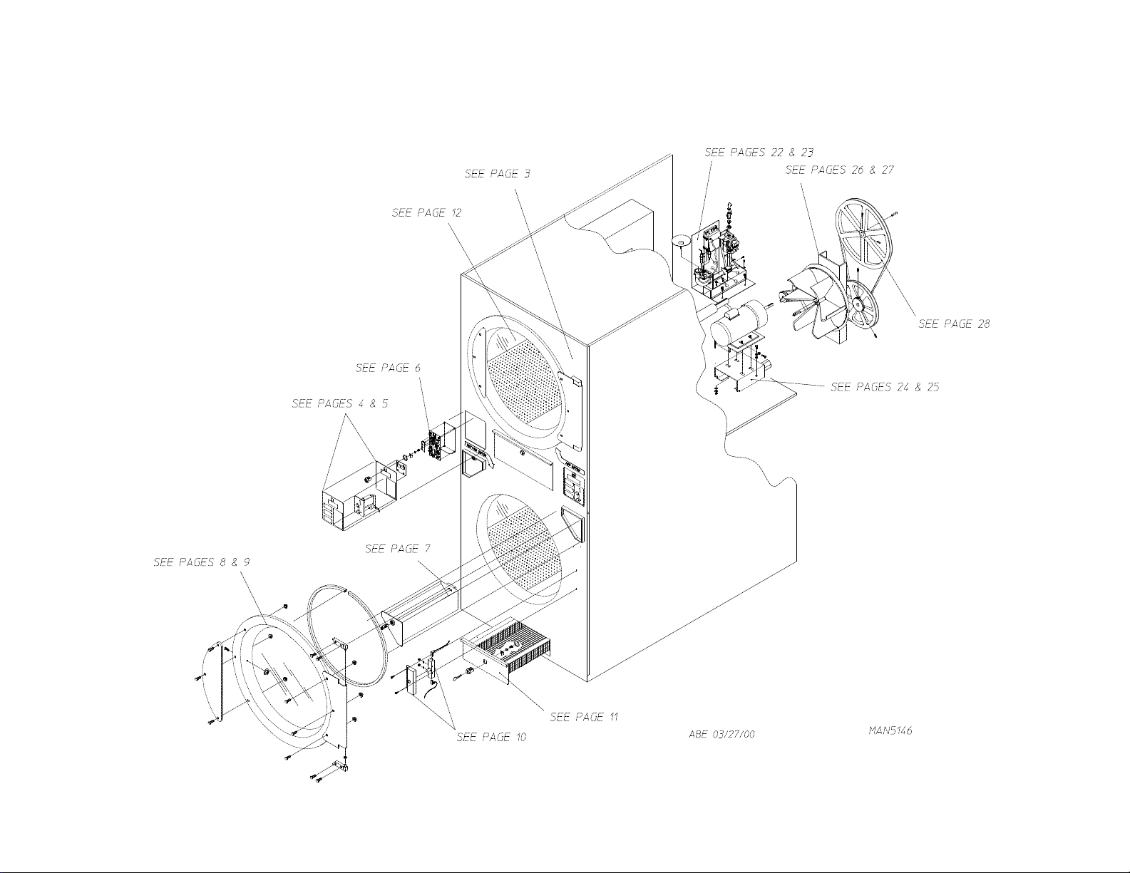
Quick Reference Diagram
For Detailed Information refer to the Table of Contents on next page.
Page 4

Table of Contents
Front Panel Assembly ...................................................................................................... 3
Left Coin Panel Assembly................................................................................................ 4
Right Coin Panel Assembly..............................................................................................5
Microprocessor 2-Piece (Computer) Panel Coin Chute Assembly ................................ 6
Coin Box/Vault Assembly (Left and Right) ..................................................................... 7
Main Door “Steel’’ Assembly...................................................................................... 8, 9
Main Door Switch Assembly ......................................................................................... 10
Lint Drawer/Basket Assembly III................................................................................... 11
Tumbler (Basket)/Support Assemblies .......................................................................... 12
Microprocessor Temperature Sensor Bracket Assembly ............................................. 13
Lint Drawer/Switch Assembly IV .................................................................................. 14
Lint Drawer/Switch Assembly III................................................................................... 15
Rear Electrical Panel Assembly................................................................................16, 17
Tumbler Bearing Mount Assembly .......................................................................... 18, 19
Sail Switch Assembly..................................................................................................... 20
Burner Hi-Limit Assembly.............................................................................................. 21
Burner Train Assembly............................................................................................. 22, 23
Drive Motor Mount Assembly
(for 60 Hz Models) ............................................................................................. 24, 25
Fan (Impellor)/Idler Bearing Assembly
(for 60 Hz Models) ............................................................................................. 26, 27
Drive and Idler Belts/Pulleys
(for 60 Hz Models) ................................................................................................... 28
Exhaust Duct Assembly ................................................................................................. 29
Rear Guard Assemblies.................................................................................................. 30
Additional Parts Available .............................................................................................. 31
Page 5
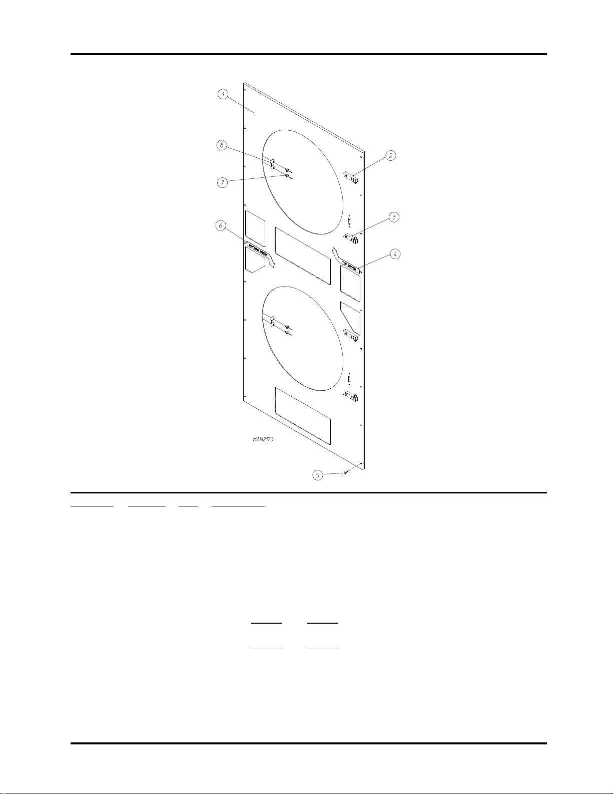
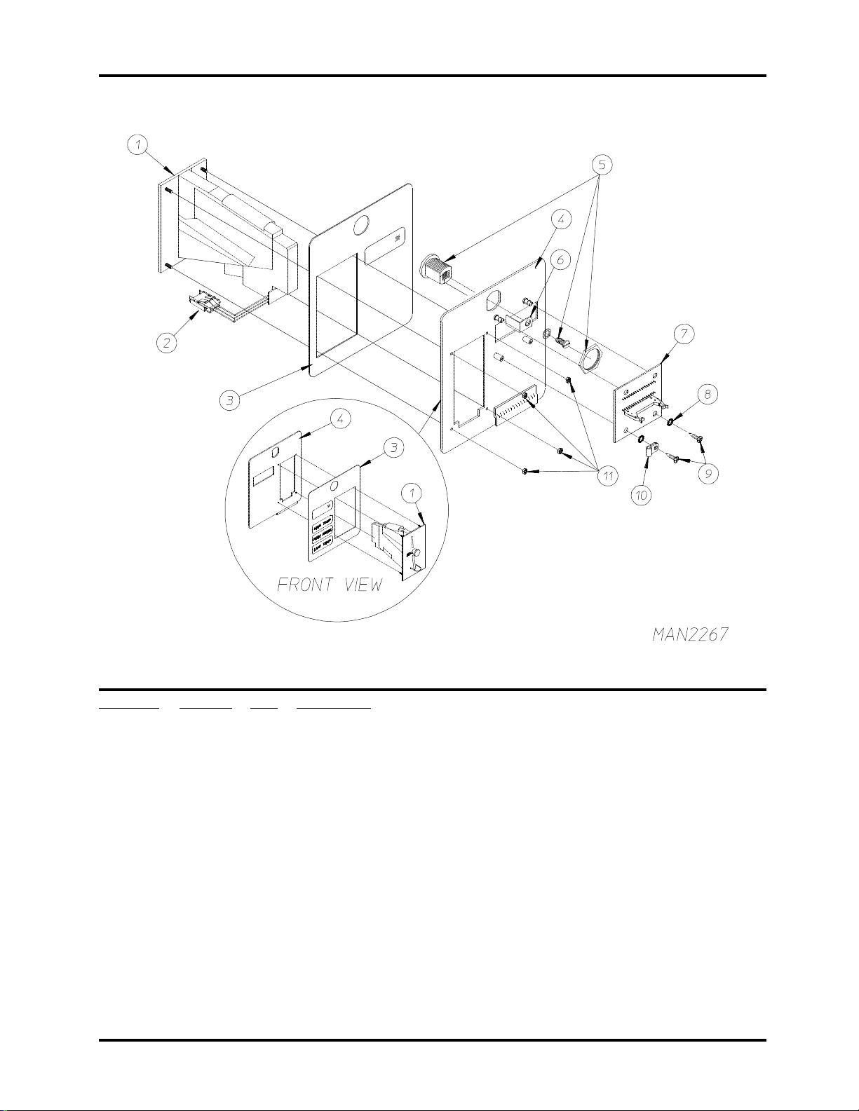
Front Panel Assembly
3
Illus. No. Part No. Qty. Description
1 881471* 1 Right Hand Textured Front Panel Assembly
(includes illus. nos. 1, 7, and 8)
881472 1 Right Hand Stainless Steel Front Panel Assembly
(includes illus. nos. 1, 7, and 8)
881473* 1 Right Hand Front Panel Assembly
(includes illus. nos. 1, 7, and 8)
2 --------- 1 Top Hinge Block Assembly
(refer to page 8
3 --------- 1 Bottom Hinge Block Assembly
(refer to page 8 and page 9)
4 112227 1 Top Arrow Label (Red)
5 150309 24 #10-16 x 1/2" Hex Head TEK Crimptite Screw
6 112226 1 Bottom Arrow Label (Blue)
7 154215 4 5/32” Pop Rivet
8 170330 2 Friction Door Catch
* Specify color when ordering.
and page 9)
Telephone: (508) 678-9000 Fax: (508) 678-9447
Page 6
4
Left Coin Panel Assembly
Illus. No. Part No. Qty. Description
1 881163 1 25¢ U.S. Hanke Coin Acceptor Assembly with Optic Switch
881450 1 25¢ Canadian Hanke Coin Acceptor with Optic Switch
881451 1 .880 Token Hanke Coin Acceptor with Optic Switch
2 881143 1 Hanke Optic Switch w/Connector
3 112564 1 Left Keypad (Blue)
4 881160 1 Coin Panel ONLY
881161 1 Left Coin Panel with Label
(includes illus. nos, 3, 4, 8, and 9)
5 160029 1 Lock (keyed NO530) ONLY with Key
160129 1 NO530 Key ONLY
6 160028 1 Lock Cam ONLY
7 137098 1 Display Board
137104 1 Display Board Ribbon Cable Assembly ... Not Illustrated
8 153010 2 #6 Star Washer
9 150005 2 #6-32 x 1/4" Phillips Round Head Machine Screw
10 120906 1 1/8" Wire Clip
11 152102 4 M3 Metric Hex Nut
American Dryer Corporation 88 Currant Road / Fall River, MA 02720-4781
Page 7
Right Coin Panel Assembly
5
Illus. No. Part No. Qty. Description
1 881163 1 25¢ U.S. Hanke Coin Acceptor Assembly with Optic Switch
881450 1 25¢ Canadian Hanke Coin Acceptor with Optic Switch
881451 1 .880 Token Hanke Coin Acceptor with Optic Switch
2 881143 1 Hanke Optic Switch w/Connector
3 112565 1 Right Keypad (Red)
4 881160 1 Coin Panel ONLY
881162 1 Right Coin Panel with Label
(includes illus. nos, 3, 4, 8, and 9)
5 160029 1 Lock (keyed NO530) ONLY with Key
160129 1 NO530 Key ONLY
6 160028 1 Lock Cam ONLY
7 137098 1 Display Board
137104 1 Display Board Ribbon Cable Assembly ... Not Illustrated
8 153010 2 #6 Star Washer
9 150005 2 #6-32 x 1/4" Phillips Round Head Machine Screw
10 120906 1 1/8" Wire Clip
11 152102 4 M3 Metric Hex Nut
Telephone: (508) 678-9000 Fax: (508) 678-9447
Page 8
6
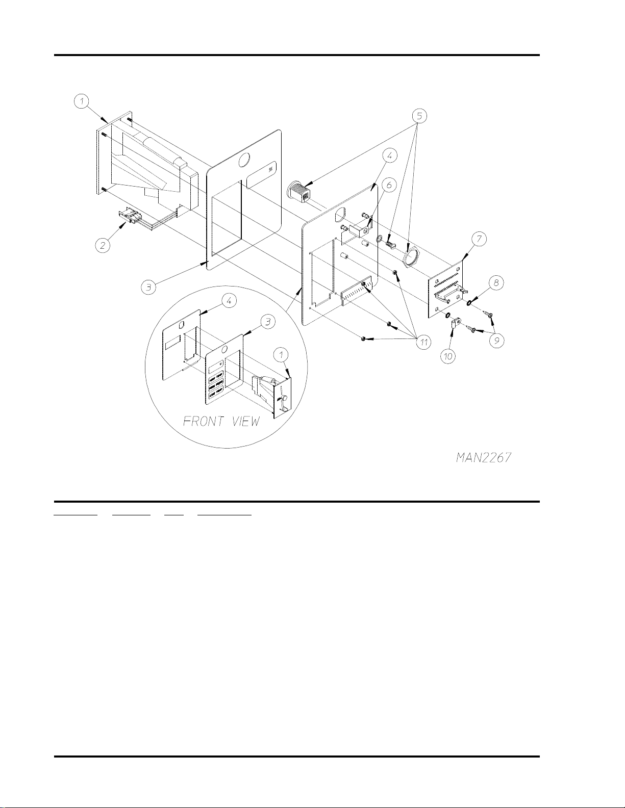
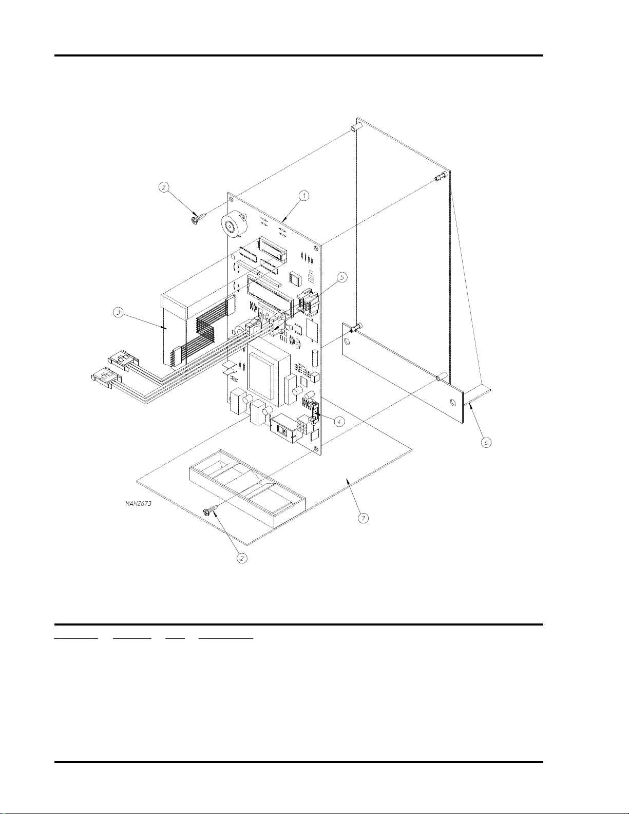
Microprocessor 2-Piece (Computer) Panel/Coin Chute Assembly
Illus. No. Part No. Qty. Description
1 137103 1 Phase 5 Microprocessor Controller (computer)
2 150005 2 #6-32 x 1/4" Phillips Round Head Machine Screw
3 137104 1 Ribbon Cable Assembly
4 136048 1 1/8-Amp (Slo Blo) Fuse ONLY
5 853071 1 or 2 Optic Switch Harness
6 853171 1 Computer Panel II
853170 1 Computer Panel Mounting Plate ... Not Illustrated
7 881484 1 2-Piece 8" Coin Chute Assembly V
American Dryer Corporation 88 Currant Road / Fall River, MA 02720-4781
Page 9
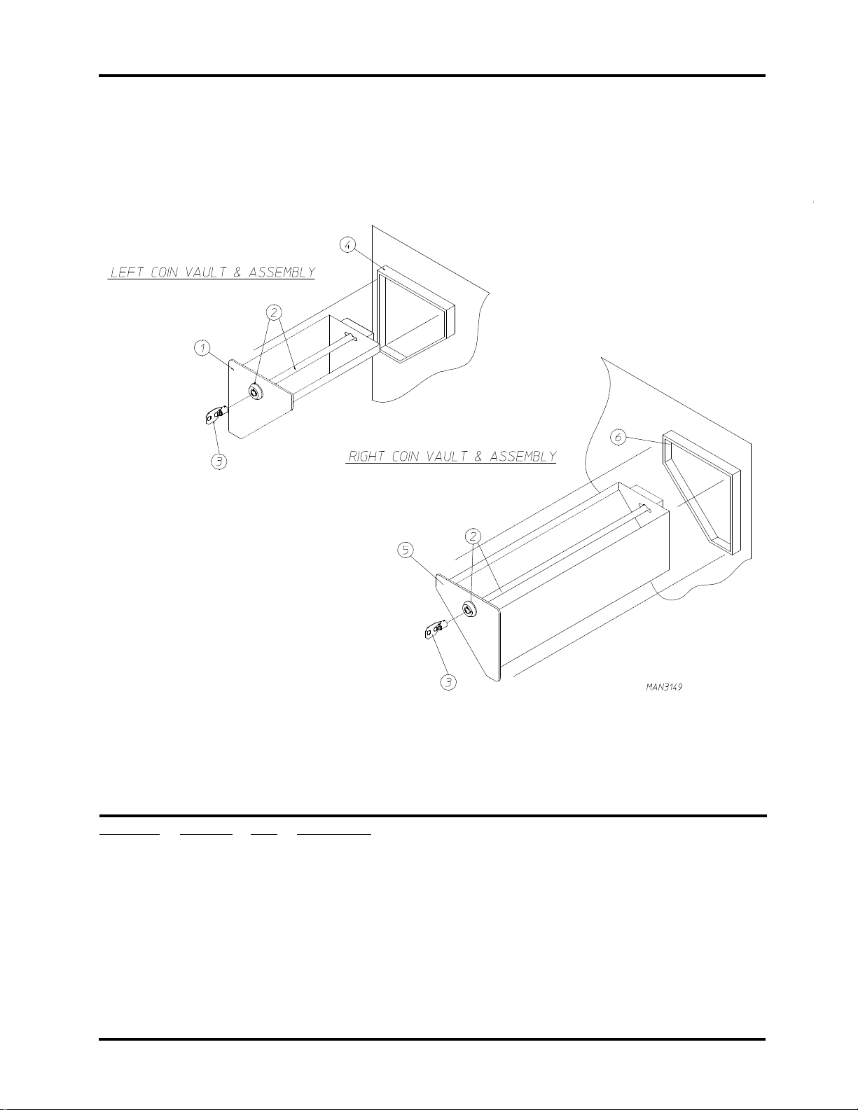
Coin Box/Vault Assembly (Left and Right)
7
Illus. No. Part No. Qty. Description
1 881174 1 Left / Right Coin Box Face Plate ONLY (Black)
881476 1 Left Coin Box with Black Face Plate Only (less Lock)
2 881474 1 Coin Box Lock Kit (includes 2 Locks with keys "keyed alike")
3* 160136 1 Coin Box Lock Key ONLY
4 881477 1 Left Coin Vault ONLY (Black)
5 881174 1 Left/Right Coin Box Face Plate ONLY (Black)
881167 1 Right Coin Box with Black Face Plate ONLY (less Lock)
6 881179 1 Right Coin Vault ONLY (Black)
* Specify key number when ordering.
Telephone: (508) 678-9000 Fax: (508) 678-9447
Page 10
8
Main Door “Steel’’ Assembly
American Dryer Corporation 88 Currant Road / Fall River, MA 02720-4781
Page 11

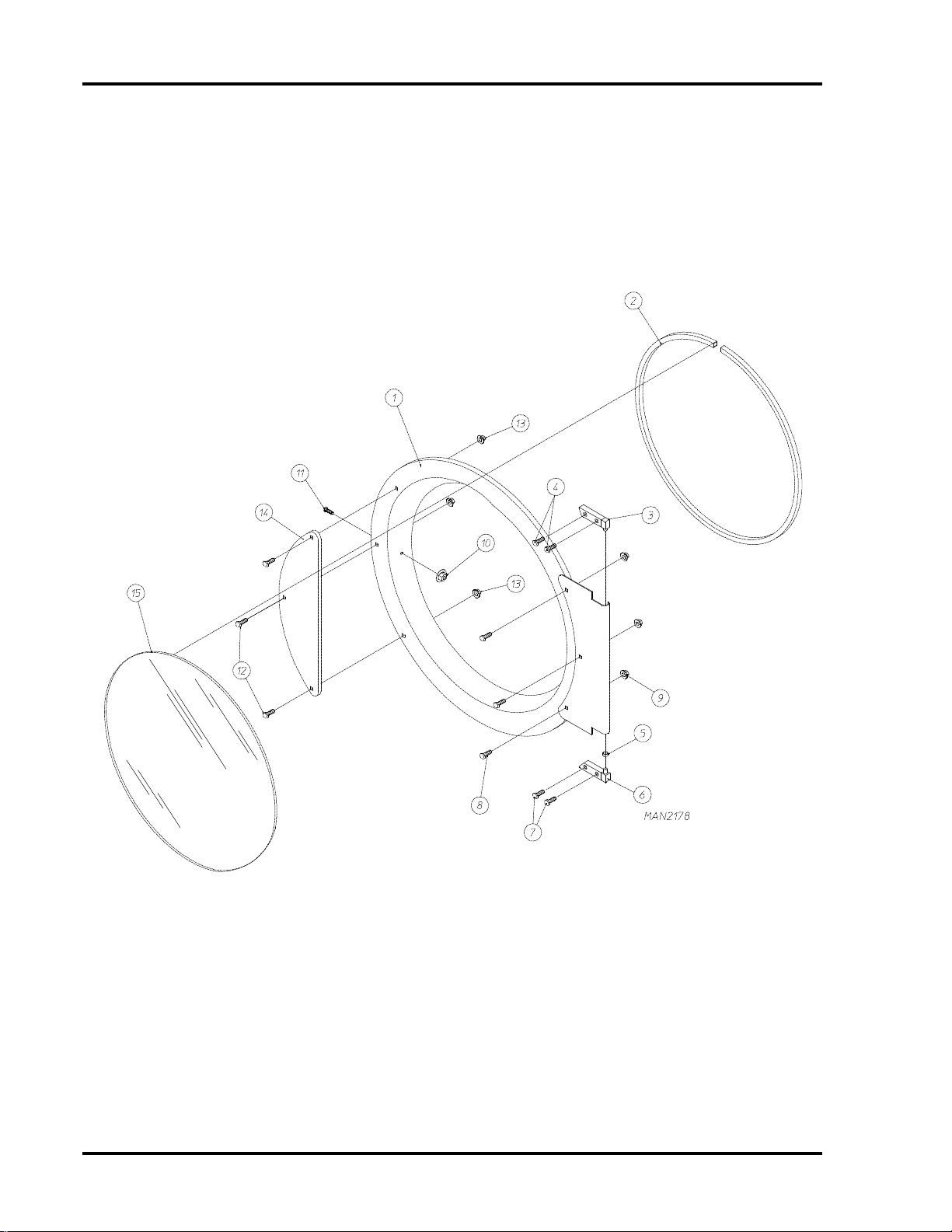
Main Door “Steel’’ Assembly
Illus. No. Part No. Qty. Description
1 881150 1 Black Main Door Assembly Complete
(includes illus. nos. 1, 2, and 8 through 15)
881207 1 Stainless Steel Main Door Assembly Complete
(includes illus. 1, 2, and 8 through 15)
2 102354 1 Door Gasket
170730 1 Glass/Gasket Adhesive (Clear) 10.3 oz. cartridge
170731 1 Glass/Gasket Adhesive (Black) 10.3 oz. cartridge
3 881152 1 Top Hinge Block Assembly (Black)
(includes illus. nos. 3 and 4)
881208 1 Stainless Steel Top Hinge Block Assembly
(includes illus. nos. 3 and 4)
4 150445 2 1/4-20 x 3/4" Black Cap Head Set Screw
150443 2 1/4-20 x 3/4" Stainless Steel Cap Head Set Screw
5 153031 1 1/4" Nylon Washer
6 881151 1 Bottom Hinge Block Assembly (Black)
(includes illus. nos. 5, 6, and 7)
881209 1 Stainless Steel Bottom Hinge Block Assembly
(includes illus. nos. 5, 6, and 7)
7 150445 2 1/4-20 x 3/4" Black Cap Head Set Screw
150443 2 1/4-20 x 3/4" Stainless Steel Cap Head Set Screw
8 150683 3 1/4-20 x 5/8" Black Carriage Bolt
150682 3 1/4-20 x 5/8" Polished Carriage Bolt
(for models with Stainless Steel Door)
9 152014 3 1/2-20 Free Spin Wash Nut
10 151010 1 #10-32 Black Hex Acorn Nut
151009 1 #10-32 Stainless Steel Hex Acorn Nut
11 150120 1 Door Latch Screw
12 150683 3 1/4-20 x 5/8" Black Carriage Bolt
150682 3 1/4-20 x 5/8" Polished Carriage Bolt
(for models with Stainless Steel Doors)
13 152014 3 1/2-20 Free Spin Wash Nut
14 881210 1 Black Main Door Handle ONLY
170333 1 Stainless Steel Main Door Handle ONLY
15 102211 1 20-7/16" Door Glass
170730 1 Glass/Gasket Adhesive (Clear) 10.3 oz. cartridge
170731 1 Glass/Gasket Adhesive (Black) 10.3 oz. cartridge
9
Telephone: (508) 678-9000 Fax: (508) 678-9447
Page 12

10
Main Door Switch Assembly
Illus. No. Part No. Qty. Description
1 150006 2 #6-32 x 7/8" Phillips Pan Head Machine Screw
2 152013 2 #6-32 Hex Nut
3 153010 2 #6 Star Washer
4 137005 1 Door Switch ONLY
5 122636 2 Flag Terminal
6 881211 1 Black Main Door Switch Housing ONLY
881212 1 Beige Main Door Switch Housing ONLY
881213 1 White Main Door Switch Housing ONLY
881214 1 Blue Main Door Switch Housing ONLY
881153 1 Black Main Door Switch Housing Complete
(includes illus. nos. 1, 2, 3, 4, and 6)
881215 1 Beige Main Door Switch Housing Complete
(includes illus. nos. 1, 2, 3, 4, and 6)
881216 1 White Main Door Switch Housing Complete
(includes illus. nos. 1, 2, 3, 4, and 6)
881217 1 Blue Main Door Switch Housing Complete
(includes illus. nos. 1, 2, 3, 4, and 6)
7 150301 2 #8-18 x 7/16" Phillips Pan Head TEK Screw
American Dryer Corporation 88 Currant Road / Fall River, MA 02720-4781
Page 13

Lint Drawer/Basket Assembly III
11
Illus. No. Part No. Qty. Description
1 881467* 1 Textured Lint Drawer Assembly III
(Less Lock and Logo)
881466 1 Stainless Steel Lint Drawer Assembly III
(Less Lock and Logo)
881468* 1 Lint Drawer Assembly III
(Less Lock and Logo)
112346 1 Wasco Dry Logo ... Not Illustrated
2 160015 1 MK-100 Lock with key (less cam)
3 160031 1 Cam Only (90° Bend)
4 160104 1 MK-100 Key ONLY
5 117604 4 Neoprene Sponge Tape (sold by the foot)
For models mfd. as of July 13, 1998
117600 4 Noise Suppressor Tape (sold by the foot)
For models mfd. prior to July 13, 1998
6 --------- 1 Lint Drawer Switch
(refer to Lint Drawer Switch Assembly IV on page 14)
(refer to Lint Drawer Switch Assembly III on page 15)
* Specify color when ordering.
Telephone: (508) 678-9000 Fax: (508) 678-9447
Page 14

12
Tumbler (Basket)/Support Assemblies
Illus. No. Part No. Qty. Description
1 800831 1 Galvanized Tumbler (Basket)/Support Assembly Complete with Felt Collar
(includes illus. nos. 1 through 11)
800721* 1 Galvanized Tumbler (Basket) ONLY
800891 1 Stainless Steel Tumbler (Basket)/Support Assembly Complete with Felt Collar
(includes illus. nos. 1 through 11)
800841* 1 Stainless Steel Tumbler (Basket) ONLY
2 301315 2 Short Galvanized Tumbler (Basket) Rib ONLY
301316 1 Tall Galvanized Tumbler (Basket) Rib ONLY
301414 2 Short Stainless Steel Tumbler (Basket) Rib ONLY
301415 1 Tall Stainless Steel Tumbler (Basket) Rib ONLY
3 150518 1 5/16-18 x 3/8" Socket Button Head Screw
4 100902 3 5/16-18 x 31" Tie Rod
5 153001 3 5/16” Flat Washer
6 154210 30 5/32” Pop Rivet
7 800617 1 Tumbler (Basket) Support ONLY
8 152004 3 5/16-18 Hex Nut
9 153002 3 5/16” Lock Washer
10 153001 3 5/16” Flat Washer
11 116003 1 Felt Collar ONLY
401010 1 #847 Adhesive for Felt Collar (5 oz. Tube)
* Felt Collar is not included and must be ordered separately.
American Dryer Corporation 88 Currant Road / Fall River, MA 02720-4781
Page 15

Microprocessor Temperature Sensor Bracket Assembly
13
Illus. No. Part No. Qty. Description
1 853021 1 Sensor Bracket ONLY
881090 1 Microprocessor Temperature Sensor Bracket Assembly Complete
(includes illus. nos. 1 through 6 and 9 through 12)
2 880251 1 Microprocessor Sensor Probe Assembly Complete
(includes illus. nos. 2 through 6)
3 154007 2 1/4" Push-On Fastener
4 121028 2 1/4" Terminal
5 122701 4 Socket Terminal ONLY
122801 1 Pin/Socket Extraction Tool
6 122605 1 4-Position Connector (Female)
7 122700 4 Pin Terminal ONLY
8 122604 1 4-Position Connector (Male)
9 130112 1 225° Thermostat ONLY
10 150005 2 #6-32 x 1/4" Phillips Round Head Machine Screw
11 153010 2 #6 Star Washer
12 152013 2 #6-32 Hex Nut
13 152014 2 1/4-20 Free Spin Wash Nut
Telephone: (508) 678-9000 Fax: (508) 678-9447
Page 16

14
Lint Drawer/Switch Assembly IV
for models mfd. as of January 31, 1997
Illus. No. Part No. Qty. Description
1 150301 2 #8-18 x 7/16" Phillips Pan Head TEK Screw
2 826303 1 Lint Drawer Switch Panel
3 150301 4 #8-18 x 7/16" Phillips Pan Head TEK Screw
4 353261 1 Lint Drawer Bracket
881494 1 Lint Drawer Switch Box Assembly (Type IV)
(includes illus. nos. 1, 2 and 4 through 9)
5 122116 1 Lint Drawer Switch
6 122636 2 .250 Insulated Flag Terminal
7 122701 4 M-N-L (Mate-N-Lock) Socket Terminal
8 122605 2 4-Pin Socket Connector
9 881502 1 Lint Drawer Switch Harness
American Dryer Corporation 88 Currant Road / Fall River, MA 02720-4781
Page 17

Lint Drawer/Switch Assembly III
for models mfd. prior to January 31, 1997
15
Illus. No. Part No. Qty. Description
1 122116 1 Lint Drawer Switch
2 122605 2 4-Pin Socket Connector
3 122701 4 M-N-L (Mate-N-Lock) Socket
4 304034 1 Lint Drawer Switch Box Cover
881493 1 Lint Drawer Switch Box Assembly (Type III)
(includes illus. nos. 1 through 5 and 8)
5 150301 2 #8-18 x 7/16" Phillips Pan Head TEK Screw
6 122700 2 Pin Terminal ONLY
122801 1 Pin/Socket Extraction Tool
7 122604 2 4-Pin Terminal
8 853104 1 Lint Drawer Switch Mounting Panel
9 150301 2 #8-18 x 7/16" Phillips Pan Head TEK Screw
10 152014 2 1/4-20 Free Spin Wash Nut
Telephone: (508) 678-9000 Fax: (508) 678-9447
Page 18

16
Rear Electrical Panel Assembly
American Dryer Corporation 88 Currant Road / Fall River, MA 02720-4781
Page 19

Rear Electrical Panel Assembly
Illus. No. Part No. Qty. Description
1 881495 1 HSI (Hot Surface Ignition) 24 VAC Transformer Kit
2 150301 2 #8-18 x 7/16" Phillips Pan Head TEK Screw
3 152014 2 1/4-20 Free Spin Wash Nut
4 150301 2 #8-18 x 7/16" Phillips Pan Head TEK Screw
5 136008 1 or 2 Fuse Block
6 136049 1 or 2 3/4-Amp (Slo Blo) Fuse
7 150301 1 or 2 #8-18 x 7/16" Phillips Pan Head TEK Screw
8 132451 1 Motor Contactor - 24 VAC
9 150301 2 #8-18 x 7/16" Phillips Pan Head TEK Screw
10 112025 1 “CAUTION - Disconnect Supply” Label
11 353161 1 Connector Bracket
12 150301 2 #8-18 x 7/16" Phillips Pan Head TEK Screw
13 122642 1 9-Pin Connector
14 122643 8 M-N-L (Mate-N-Lock) Pin
15 122645 1 6-Pin Connector
16 122643 6 M-N-L (Mate-N-Lock) Pin
17 122645 1 4-Pin Connector
18 122643 4 Mate-N-Lock Pin
19 150301 2 #8-18 x 7/16" Phillips Pan Head TEK Screw
20 353153 1 Rear Electrical Box Cover
21 112046 1 “Computer Ground” Label
22 112014 1 “High Voltage” Label
23 112039 1 “Black/White/Green Ground” Label
24* 150008 2 #6-32 x 1-1/4" Round Head Machine Screw
25* 120701 1 4-Position Terminal Block
26* 881222 1 Power Distribution Block Mounting Bracket
27* 151000 2 #6-32 Pal Nut
28* 153528 2 #8-32 x 1/2" Clinch Stud
29* 121300 2 Bushing
30* 152001 2 #8-32 Hex Nut
31 121010 1 L-70 Ground Lug
32 153007 1 1/4" Lock Washer
33 152002 1 1/4"-20 Hex Nut
34 131814 1 Relay
(for use on 120 VAC Models Only)
131815 1 Relay
(for use on 240 VAC Models Only)
35 150301 2 #8-18 x 7/16" Phillips Pan Head TEK Screw
36 824828 1 R.C. Network
17
* For use on Top Tumbler (basket) ONLY.
Telephone: (508) 678-9000 Fax: (508) 678-9447
Page 20

18
Tumbler Bearing Mount Assembly
American Dryer Corporation 88 Currant Road / Fall River, MA 02720-4781
Page 21

Tumbler Bearing Mount Assembly
Illus. No. Part No. Qty. Description
1 880203 1 1-3/8" Flange Bearing with Nylock Set Screws
880938 1 Cone Point Set Screw Kit ... Not Illustrated
2 153005 4 3/8" Lock Washer
3 152005 4 3/8-16 Hex Nut
4 153004 2 3/8" Flat Washer
5 153005 2 3/8" Lock Washer
6 152005 2 3/8-16 Hex Nut
7 880881 1 1-3/8" Pillow Block Bearing with Rotation Sensor Magnet
880938 1 Cone Point Set Screw Kit ... Not Illustrated
8 824807 1 Rotational Sensor Magnetic Switch Assembly
9 853040 1 Tumbler Bearing Support only
10 152004 2 5/16-18 Hex Nut
11 150621 2 5/16-18 x 1-1/2" Hex Head Machine Bolt
12 150601 2 3/8-16 x 1-1/2" Hex Head Tap Bolt
13 150501 2 5/16-18 x 3/4" Hex Head Machine Bolt
14 153002 2 5/16" Lock Washer
15 153001 2 5/16" Flat Washer
16 150610 2 5/16-18 x 1-1/2" Allen Set Screw
17 152004 2 5/16-18 Hex Nut
18 153001 2 5/16" Flat Washer
19 153002 2 5/16" Lock Washer
20 150501 2 5/16-18 x 3/4" Hex Head Machine Bolt
19
Telephone: (508) 678-9000 Fax: (508) 678-9447
Page 22

20
Sail Switch Assembly
Illus. No. Part No. Qty. Description
1 150301 2 #8-18 x 7/16" Phillips Pan Head TEK Screw
2 802800 1 Sail Switch Box with Cover and Bracket ONLY
(includes illus. nos. 4 and 8)
802801 1 Sail Switch Box Assembly Complete
(includes illus. nos. 2 through 10)
3 154004 1 Twin Speed Nut
4 150309 2 10-16 x 1/2” Hex Head TEK Crimptite Screw
5 802709 1 Sail Switch Box Cover and Bracket ONLY
6 122200 1 Sail Switch ONLY
7 150303 2 #4 x 3/4" Pan Head “A” Machine Screw
8 105500 1 Sail Switch Actuator Rod
9 319202 1 Sail Switch Damper (embossed)
10 154002 1 1/8” Push-on Fastener
11 853105 1 Burner Box ONLY
American Dryer Corporation 88 Currant Road / Fall River, MA 02720-4781
Page 23

Burner Hi-Limit/Hood Assembly
21
Illus. No. Part No. Qty. Description
1 881223 1 HSI (Hot Surface Ignition) Burner Hood
2 130401 1 330° Hi-Limit
3 150300 2 #10 x 1/2" Hex Washer TEK Screw
4 150300 4 #10 x 1/2" Hex Washer TEK Screw
Telephone: (508) 678-9000 Fax: (508) 678-9447
Page 24

22
Burner Train Assembly
American Dryer Corporation 88 Currant Road / Fall River, MA 02720-4781
Page 25

Burner Train Assembly
Illus. No. Part No. Qty. Description
1* 881469 1 Natural Gas Burner Assembly Complete less Orifice
(includes illus. nos. 1 through 19)
881470 1 L.P. Gas Burner Assembly Complete less Orifice
(includes illus. nos. 1 through 19)
2 142502 1 1/2” x 3/4” Street Elbow
3 881372 1 1/2” F.P.T. Straight Shut Off with Tail Piece
4 128927 1 1/2” 24 VAC Redundant (natural gas) Gas Valve
880960 1 1/2” 24 VAC L.P. (liquid propane) Gas Valve
140411 1 1/2” 24 VAC Gas Valve L.P. (liquid propane) Conversion Kit
5 353237 1 Notched Double Sided Pipe Bracket
6 141211 1 1/2” Single Port Manifold
7 150300 2 #10 x 1/2" Hex Washer TEK Screw
8 353222 1 HSI (Hot Surface Ignition) Manifold Pipe Bracket
9 318009 1 Burner Tube Bracket
10 151001 4 #8 Pal Nut
11 141131 1 Upshot Burner Tube with Spreader
12 353099 1 Burner Tube Angle Bracket
13 150309 2 6-32 x 1/2” Hex Head TEK Crimptite Screw
14 150002 1 6-32 x 1” Phillips Round Head Machine Screw
15 881479 1 Hot Surface Ignitor - 24 VAC
16 151000 1 #6 Pal Nut
17 128918 1 Flame Probe
18 150315 1 #6 x 3/8” Phillips Pan Head Screw
19 881500 1 HSI (Hot Surface Ignition) Module II
(for models mfd. as of January 1, 1997)
128974 1 HSI (Hot Surface Ignition) Module
(for models mfd. prior to December 31, 1996)
20** 140836 1 #10 Burner Orifice (natural gas) ONLY
140855 1 #33 Burner Orifice (liquid propane) ONLY
881119 1 ADG-530HS L.P. Conversion Kit
(includes parts to convert both top and bottom tumblers)
23
* Burner Orifice is not included and must be ordered separately.
**Consult the factory for elevations over 2,000 feet.
Telephone: (508) 678-9000 Fax: (508) 678-9447
Page 26

24
Drive Motor Mount Assembly
for 60 Hz Models
American Dryer Corporation 88 Currant Road / Fall River, MA 02720-4781
Page 27

Drive Motor Mount Assembly
for 60 Hz Models
Illus. No. Part No. Qty. Description
1 100718 1 3/16" x 3/16" x 2-1/4" Key
2 101133 1 2-1/4” x 5/8" Pulley
3 100171 1 4L-440 V-Belt
4 101207 1 3.0 x 5/8" Pulley
5 100156 1 5L-330 V-Belt
6* 181022 1 3/4 HP 120/230v 1ø 60 Hz Motor
(for models mfd. as of May 22, 1998)
881096 1 3/4 HP 120/230v 1ø 60 Hz Drive Motor Mount Assembly
(for models mfd. prior to May 22, 1998)
7 152004 4 5/16-18 Hex Nut
8 153002 4 5/16" Lock Washer
9 153001 4 5/16" Flat Washer
10 853087 1 Motor Mount Slide Mount Assembly ONLY
11 152005 1 3/8-16 Hex Nut
12 150601 1 3/8-16 x 2" Hex Head Tap Bolt
13 853042 1 Motor Base Assembly ONLY
14 152004 4 5/16-18 Hex Nut
15 153002 4 5/16" Lock Washer
16 153001 4 5/16" Flat Washer
17 153001 4 5/16" Flat Washer
18 153002 4 5/16" Lock Washer
19 150501 4 5/16-18 x 3/4" Hex Head Machine Bolt
--- 881096* 1 3/4 HP 120/230v 1ø 60 Hz Drive Motor Mount Assembly Complete
(includes illus. nos. 1, 2, 4, and 6 through 16)
25
* Specify voltage when ordering.
Telephone: (508) 678-9000 Fax: (508) 678-9447
Page 28

26
Impellor/Idler Bearing Assemblies
for 60 Hz Models
American Dryer Corporation 88 Currant Road / Fall River, MA 02720-4781
Page 29

Impellor/Idler Bearing Assemblies
for 60 Hz Models
Illus. No. Part No. Qty. Description
1 100701 1 3/16" x 3/16" x 1" Key
2 101206 1 2.8 x 5/8" Pulley
3 152002 4 1/4-20 Hex Nut
4 153007 4 1/4" Lock Washer
5 154324 4 #10-32 x 1/4" Cone Point Set Screw
6 881361 2 5/8" Flange Bearing
7 881225 1 Impellor (Fan/Blower) Bearing Mount ONLY
8 101129 1 9" Pulley
9 154301 2 5/16-18 x 1” Allen (Cone Point) Set Screw
10 100705 1 3/16" x 3/16" x 1-3/8" Key
11 301850 1 Idler Shaft
12 150529 3 1/4-20 x 2-1/4" Carriage Bolt
13 --------- 4 Flanges (part of Part No. 100214 Bearing)
14 100214 2 5/8" Flange Bearing
15 150617 2 3/8-16 x 1" Hex Head Machine Bolt
16 153005 2 3/8" Lock Washer
17 153004 2 3/8" Flat Washer
18 152020 1 5/16-18 Square Nut
19 152004 1 5/16-18 Hex Nut
20 150509 1 5/16-18 x 3" Hex Head Machine Bolt
21 801016 1 Cast Idler Assembly Complete
(includes illus. nos. 10 through 23)
100406 1 Cast Idler Bearing Mount Assembly
22 153007 3 1/4" Lock Washer
23 152002 3 1/4-20 Hex Nut
24 881226 1 Impellor (fan/blower) Mount ONLY
(includes illus. no. 33)
25 153004 4 3/8" Flat Washer
26 153005 4 3/8" Lock Washer
27 150508 4 3/8-16 x 3/4" Hex Head Machine Bolt
28 153050 3 or 4 1/2" x 1-1/16" Flat Washer
29 100604 1 12-1/2” Impellor fan/blower)
30 100723 1 1/8 x 1/8 x 1 3/8'" Key
31 152006 2 1/2-20 Left Hand Jam Nut
32 353111 1 Fan Shaft
33 117604 4 Neoprene Sponge Tape (sold by the foot)
For models mfd. as of July 13, 1998
117600 4 Noise Suppressor Tape (sold by the foot)
For models mfd. prior to July 13, 1998
34 116011 1 3-1/2" x 4" Felt Bearing Seal
27
Telephone: (508) 678-9000 Fax: (508) 678-9447
Page 30

28
Drive and Idler Belts/Pulleys
for 60 Hz Models
Illus. No. Part No. Qty. Description
1 --------- 1 Tumbler (Basket) Support
(refer to page 12)
2 101100 1 18" Pulley
- 154301 2 5/16-18 x 1" Allen (Cone Point) Set Screw
3 100713 1 1/4" x 1/4" x 7/8" Key
4 100106 1 5L-690 V-Belt
5 101206 1 2.8 x 5/8" Pulley
6 101129 1 9" x 2-1/2" Compound Pulley
7 --------- 1 Idler Assembly
(refer to page 26
8 100171 1 4L-440 V-Belt
9 154301 2 5/16-18 x 1” Allen (Cone Point) Set Screw
10 101133 1 2-1/4” x 5/8" Pulley
11 100156 1 5L-330 V-Belt
12 101207 1 3.0 x 5/8" Pulley
13 --------- 1 Drive Motor Mount Assembly
(refer to page 24
14 100718 1 3/16" x 3/16" x 2-1/4" Key
and page 27)
and page 25)
American Dryer Corporation 88 Currant Road / Fall River, MA 02720-4781
Page 31

Exhaust Duct Assembly
29
Illus. No. Part No. Qty. Description
1 143536 1 6" x 45° Elbow
2 143536 2 6" x 45° Elbow
- 117505 6 Aluminum Duct Tape (sold by the foot)
- 881373 1 6" x 45° Elbow with 6" Damper
Telephone: (508) 678-9000 Fax: (508) 678-9447
Page 32

30
Rear Guard Assemblies
Illus. No. Part No. Qty. Description
1 353147 2 Upper and Lower Back Guard
2 150301 14 #8-18 x 7/16" Phillips Pan Head TEK Screw
3 112041 1 “CAUTION - Exhaust/Lint Screen” Label
4 112086 1 “Installation Instructions” Label
5 103500 4 Leveling Leg
American Dryer Corporation 88 Currant Road / Fall River, MA 02720-4781
Page 33

Additional Parts Available
Part No. Description
112179 ADG-530HS/WDA-530 Installation/Operators Manual
112533 Phase 5 Coin "PROGRAM LOCATION SUMMARY" Label
120903 Closed End Connector
121026 Tab Receptacle Combination
121495 4" Wire Tie
121500 7" Wire Tie
122804 Manometer (used to Measure Gas Pressure)
404502 White Brush-In-Cap Bottle Touch Up Paint
404506 Beige Brush-In-Cap Bottle Touch-Up Paint
404507 Cornflower Blue Brush-In-Cap Bottle Touch Up Paint
410001 1/2" Allen Wrench (used to remove Gas Valve Brass Tail Piece)
880200 Electrical Terminal (Assortment) Kit
881299 Loctite Kit (includes 2 [two] .02 oz tubes of #290 Wicking Loctite)
31
Telephone: (508) 678-9000 Fax: (508) 678-9447
Page 34

ADC 450171 1- 02/05/97-100 2* 01/30/98-50 3- 02/25/98-50
4- 08/20/99-50 5* 03/27/00-50 6* 09/12/00-25
7- 09/26/00-75 8- 11/20/00-100
 Loading...