


AD-115ES
Installation/Operator's Manual
WARNING: For your safety the information in this manual must be followed to minimize the risk of fire or explosion or to prevent property damage, personal injury or death.
Do not store or use gasoline or other flammable vapor and liquids in the vicinity of this or any other appliance.
WHAT DO YOU DO IF YOU SMELL GAS
*Do not try to light any appliance.
*Do not touch any electrical switch; do not use any phone in your building.
*Clear the room, building or area of all occupants.
*Immediately call your gas supplier from a neighbor's phone. Follow the gas supplier's instructions.
*If you cannot reach your gas supplier, call the fire department.
Installation and service must be performed by a qualified installer, service agency or the gas supplier.
AVERTISSEMENT: Assurez-vous de bien suivre les instructions données dans cette notice pour réduire au minimum le risque d’incendie ou d’explosion ou pour éviter tout dommage matériel, toute blessure ou la mort.
Ne pas entreposer ni utiliser d’essence ni d’autres vapeurs ou liquides inflammables dans le voisinage de cet appareil ou de tout autre appareil.
QUE FAIRE SI VOUS SENTEZ UNE ODEUR DE GAZ:
*Ne pas tenter d’allumer d’appareil.
*Ne touchez à aucun interrupteur. Ne pas vous servir des téléphones se trouvant dans le bâtiment où vous vous trouvez..
*Évacuez la pièce, le bâtiment ou la zone.
*Appelez immédiatement votre fournisseur de gaz depuis un voisin. Suivez les instructions du fournisseur.
*Si vous ne pouvez rejoindre le fournisseur de gaz, appelez le service des incendies.
L’installation et l’entretien doivent être assurés par un installateur ou un service d’entretien qualifié ou par le fournisseur de gaz.
For replacement parts, contact the distributor from which the dryer was purchased or
American Dryer Corporation
88 Currant Road
Fall River MA 02720-4781
Telephone: (508) 678-9000 / Fax: (508) 678-9447 e-mail: techsupport@amdry.com
010500JEV/abe |
ADC Part No. 113119 |
Retain This Manual In A Safe Place For Future Reference
American Dryer Corporation products embody advanced concepts in engineering, design, and safety. If this product is properly maintained, it will provide many years of safe, efficient, and trouble-free operation.
ONLY qualified technicians should service this equipment.
OBSERVE ALL SAFETY PRECAUTIONS displayed on the equipment or specified in the installation/operator's manual included with the dryer.
The following “FOR YOUR SAFETY” caution must be posted near the dryer in a prominent location.
FOR YOUR SAFETY
Do not store or use gasoline or other flammable vapors or liquids in the vicinity of this or any other appliance.
POUR VOTRE SÉCURITÉ
Ne pas entreposer ni utiliser d’essence ni d’autres vapeurs ou liquides inflammables dans le voisinage de cet appareil ou de yout autre appareil.
We have tried to make this manual as complete as possible and hope you will find it useful. ADC reserves the right to make changes from time to time, without notice or obligation, in prices, specifications, colors, and material, and to change or discontinue models.
Important
For your convenience, log the following information:
DATE OF PURCHASE |
|
MODEL NO. |
AD-115ES
DISTRIBUTORS NAME
Serial Number(s)
Replacement parts can be obtained from your distributor or the ADC factory. When ordering replacement parts from the factory, you can FAX your order to ADC at (508) 678-9447 or telephone your orders directly to the ADC Parts Department at (508) 678-9000. Please specify the dryer model number and serial number in addition to the description and part number, so that your order is processed accurately and promptly.
“IMPORTANT NOTE TO PURCHASER”
Information must be obtained from your local gas supplier on the instructions to be followed if the user smells gas. These instructions must be posted in a prominent location near the dryer.
IMPORTANT
YOU MUST DISCONNECT and LOCKOUTTHE ELECTRIC SUPPLYand THE GAS SUPPLY or THE STEAM SUPPLY BEFORE ANY COVERS or GUARDS ARE REMOVEDFROMTHEMACHINETOALLOWACCESS FORCLEANING,ADJUSTING, INSTALLATION, or TESTING OFANY EQUIPMENT per OSHA (Occupational Safety and HealthAdministration) STANDARDS.
“Caution: Label all wires prior to disconnection when servicing controls. Wiring errors can cause improper operation.”
«Attention: Lor des opérations d’entretien des commandes étiqueter tous fils avant de les déconnecter. Toute erreur de câblage peut étre une source de danger et de panne.»
CAUTION
DRYERS SHOULD NEVER BE LEFT UNATTENDEDWHILE IN OPERATION.
WARNING
CHILDREN SHOULD NOT BEALLOWEDTO PLAYON OR NEAR THE DRYER(S). CHILDREN SHOULD BE SUPERVISED IFNEAR DRYERS IN OPERATION.
FOR YOUR SAFETY
DO NOT DRYMOPHEADS IN THE DRYER.
DO NOT USE DRYER IN THE PRESENCE OF DRYCLEANING FUMES.
WARNING
UNDER NO CIRCUMSTANCES should the door switch or the heat circuit devices ever be disabled.
WARNING
The dryer must never be operated with any of the back guards, outer tops, or service panels removed. PERSONALINJURY or FIRE COULD RESULT.
WARNING
DRYER MUST NEVER BE OPERATED WITHOUTTHE LINT FILTER/SCREEN IN PLACE, EVEN IF AN EXTERNAL LINT COLLECTION SYSTEM IS USED.
IMPORTANT
PLEASE OBSERVEALLSAFETYPRECAUTIONS displayed on the equipment and/or specified in the installation and operator's manual included with the dryer.
Dryers must not be installed or stored in an area where it will be exposed to water or weather.
The wiring diagram for the dryer is located in the front electrical control box area.
Table of Contents
SECTION I |
|
IMPORTANT INFORMATION ............................................................................... |
3 |
A. Receiving and Handling ............................................................................................................... |
3 |
B. Safety Precautions ....................................................................................................................... |
4 |
SECTION II |
|
SPECIFICATIONS/COMPONENT IDENTIFICATION .................................... |
6 |
A. Specifications .............................................................................................................................. |
6 |
B. Component Identification ............................................................................................................. |
8 |
SECTION III |
|
INSTALLATION PROCEDURES ......................................................................... |
10 |
A. Location Requirements .............................................................................................................. |
10 |
B. Unpacking and Setting Up ......................................................................................................... |
11 |
C. Dryer Enclosure Requirements .................................................................................................. |
14 |
D. FreshAir Supply ....................................................................................................................... |
15 |
E. Exhaust Requirements ............................................................................................................... |
16 |
F. Electrical Information ................................................................................................................ |
26 |
G. Gas Information ......................................................................................................................... |
33 |
H. Steam Information ..................................................................................................................... |
37 |
I. Preparation For Operation/Start-Up .......................................................................................... |
41 |
J. Preoperational Tests .................................................................................................................. |
42 |
K. Shut Down Instructions ............................................................................................................. |
44 |
SECTION IV |
|
SERVICE AND PARTS INFORMATION ............................................................ |
45 |
A. Service ..................................................................................................................................... |
45 |
B. Parts ......................................................................................................................................... |
45 |
SECTION V |
|
WARRANTY INFORMATION .............................................................................. |
46 |
A. Returning Warranty Card(s) ...................................................................................................... |
46 |
B. Warranty ................................................................................................................................... |
46 |
B. Returning Warranty Part(s) ........................................................................................................ |
46 |
SECTION VI |
|
ROUTINE MAINTENANCE .................................................................................. |
48 |
A. Cleaning ................................................................................................................................... |
48 |
B. Adjustments .............................................................................................................................. |
50 |
C. Lubrication ............................................................................................................................... |
50 |
SECTION VII |
|
TROUBLESHOOTING ........................................................................................... |
51 |
SECTION VIII |
|
PROCEDURE FOR FUNCTIONAL CHECK OF REPLACEMENT |
|
COMPONENTS ....................................................................................................... |
58 |
SECTION IX |
|
BURNER and LINT (TUMBLER) CHAMBER MANUAL RESET |
|
HI-LIMIT INSTRUCTIONS |
|
Gas Models .................................................................................................................................... |
61 |
Electric/Steam Models .................................................................................................................... |
62 |

SECTION I
IMPORTANT INFORMATION
A. RECEIVING and HANDLING
The dryer is shipped in a protective stretch wrap cover with protective cardboard corners and top cover (or optional box) as a means of preventing damage in transit. Upon delivery, the dryer and/or packaging, and wooden skid should be visually inspected for shipping damage. If any damage whatsoever is noticed, inspect further before delivering carrier leaves.
Dryers damaged in shipment:
1.ALL dryers should be inspected upon receipt and before they are signed for.
2.If there is suspected damage or actual damage, the trucker's receipt should be so noted.
3.If the dryer is damaged beyond repair, it should be refused. Those dryers which were not damaged in a damaged shipment should be accepted, but the number received and the number refused must be noted on the receipt.
4.If you determine that the dryer was damaged after the trucker has left your location, you should call the delivering carrier's freight terminal immediately and file a claim. The freight company considers this concealed damage. This type of freight claim is very difficult to get paid and becomes extremely difficult when more than a day or two passes after the freight was delivered. It is your responsibility to file freight claims. Dryer/parts damaged in transit cannot be claimed under warranty.
5.Freight claims are the responsibility of the consignee, and ALL claims must be filed at the receiving end. ADC assumes no responsibility for freight claims or damages.
6.If you need assistance in handling the situation, please contact the ADC Traffic Manager at (508) 678-9000.
IMPORTANT: The dryer must be transported and handled in an upright position at all times.
3
B. SAFETY PRECAUTIONS
WARNING: For your safety, the information in this manual must be followed to minimize the risk of fire or explosion or to prevent property damage, personal injury, or loss of life.
WARNING: The dryer must never be operated with any of the back guards, outer tops, or service panels removed. PERSONAL INJURY or FIRE COULD RESULT.
1.DO NOT store or use gasoline or other flammable vapors and liquids in the vicinity of this or any other appliance.
2.Purchaser and user should consult the local gas supplier for proper instructions to be followed in the event the user smells gas. The instructions should be posted in a prominent location.
3.WHAT TO DO IF YOU SMELL GAS...
a.DO NOT try to light any appliance.
b.DO NOT touch any electrical switch.
c.DO NOT use any phone in your building.
d.Clear the room, building, or area of ALL occupants.
e.Immediately call your gas supplier from a neighbor's phone. Follow the gas supplier's instructions.
f.If you cannot reach your gas supplier, call the fire department.
4.Installation and service must be performed by a qualified installer, service agency, or gas supplier.
5.Dryers must be exhausted to the outdoors.
6.Although ADC produces a very versatile machine, there are some articles that, due to fabric composition or cleaning method, should not be dried in it.
WARNING: Dry only water-washed fabrics. DO NOT dry articles spotted or washed in dry cleaning solvents, a combustible detergent, or "all purpose" cleaner.
EXPLOSION COULD RESULT.
WARNING: DO NOT dry rags or articles coated or contaminated with gasoline, kerosene, oil, paint, and wax.
EXPLOSION COULD RESULT.
WARNING: DO NOT dry mop heads. Contamination by wax or flammable solvents will create a fire hazard.
WARNING: DO NOT use heat for drying articles that contain plastic, foam, sponge rubber, or similarly textured rubber materials. Drying in a heated basket (tumbler) may damage plastics or rubber and also may be a fire hazard.
4

7.A program should be established for the inspection and cleaning of lint in the heating unit area, exhaust duct work, and inside the dryer. The frequency of inspection and cleaning can best be determined from experience at each location.
WARNING: THE COLLECTION OF LINT IN THE BURNERAREAand EXHAUST DUCT
WORK CAN CREATEAPOTENTIALFIRE HAZARD.
8.For personal safety, the dryer must be electrically grounded in accordance with local codes and/or the National Electric Code ANSI/NFPA NO. 70-LATEST EDITION or in Canada, the CANADIAN ELECTRICAL CODES PARTS 1 & 2 CSA C22.1-1990 or LATEST EDITION.
NOTE: Failure to do so will VOID THE WARRANTY.
9.UNDER NO CIRCUMSTANCES should the dryer door switches, lint door switch, heat safety circuit ever be disabled.
WARNING: PERSONALINJURY or FIRE COULD RESULT.
10.This dryer is not to be used in the presence of dry cleaning solvents or fumes.
11.Remove articles from the dryer as soon as the drying cycle has been completed.
WARNING: Articles left in the dryer after the drying and cooling cycles have been completed can create a fire hazard.
12. READ and FOLLOW ALL CAUTION and DIRECTION LABELS ATTACHED TO THE DRYER.
WARNING: YOU MUST DISCONNECT and LOCKOUT THE ELECTRIC SUPPLYand
THE GAS SUPPLY BEFOREANY COVERS or GUARDSARE REMOVED FROM THE MACHINE TOALLOWACCESS FOR CLEANING, ADJUSTING, INSTALLATION, or TESTING OFANY EQUIPMENT per OSHA (Occupational Safety and Health Administration) STANDARDS.
5

SECTION II
SPECIFICATIONS/COMPONENT IDENTIFICATION
A. SPECIFICATIONS
Maximum Capacity (DRY WEIGHT) |
115 lbs. |
|
|
52.2 kg |
|||||
|
|
|
|
|
|
|
|
|
|
Basket Diameter |
42" |
|
|
106.7 cm |
|||||
|
|
|
|
|
|
|
|
|
|
Basket Depth |
42" |
|
|
106.7 cm |
|||||
|
|
|
|
|
|
|
|
|
|
Basket Motor |
3/4 HP |
|
|
.560 kw |
|||||
|
|
|
|
|
|
|
|
|
|
Blower Motor |
3 HP |
|
|
2.238 kw |
|||||
|
|
|
|
|
|
|
|
|
|
Door Opening (DIAMETER) |
31-3/8" |
|
|
79.7 cm |
|||||
|
|
|
|
|
|
|
|
|
|
Basket Volume |
33.7 cu. ft. |
|
|
.98 cu. m. |
|||||
|
|
|
|
|
|
|
|
|
|
Dryers Per 20’/40’ Container |
|
|
|
|
4/8 |
|
|
||
|
|
|
|
|
|
|
|
|
|
Dryers Per 45’/48’ Truck |
|
|
|
9/10 |
|
|
|||
|
|
|
|
|
|
|
|
||
|
Voltage Available* |
208-460v |
3ø |
3,4w 50/60 Hz |
|||||
|
|
|
|
|
|
|
|
||
Gas |
Heat Input |
343,000 btu/hr |
|
86,436 kcal/hr |
|||||
|
|
|
|
|
|
|
|
||
Approx. Weight (UNCRATED) |
1,300 lbs. |
|
|
591 kg |
|||||
|
|
|
|
|
|
|
|
||
Approx. Weight (CRATED) |
1,500 lbs. |
|
|
682 kg |
|||||
|
|
|
|
|
|
|
|
|
|
|
Airflow |
2,100 cfm |
|
|
59.4 cmm |
||||
|
|
|
|
|
|
|
|
|
|
|
Inlet Size |
|
1" |
|
|
2.54 cm |
|||
|
|
|
|
|
|
|
|
|
|
Electric |
Voltage Available** |
208-460v |
3ø |
3,4w |
50/60 Hz |
||||
|
|
|
|
|
|
|
|
||
|
|
|
|
Oven Size |
|
|
|||
|
|
|
|
|
|
|
|
||
|
kw |
btu/hr |
|
kcal/hr |
|
Airflow |
|||
|
|
|
|
|
|
|
|||
|
60 |
205,000 |
|
51,620 |
1,700 cfm |
48.5 cmm |
|||
|
|
|
|
|
|
|
|||
|
72 |
246,000 |
|
61,944 |
2,100 cfm |
59.5 cmm |
|||
|
|
|
|
|
|
|
|
|
|
|
80 |
273,300 |
|
68,827 |
2,420 cfm |
68.5 cmm |
|||
|
|
|
|||||||
|
|
|
|
|
|
|
|
|
|
|
Voltage Available* |
208-460v |
3ø |
3,4w |
50/60 Hz |
||||
|
|
|
|
|
|
|
|
|
|
|
Approx. Weight (UNCRATED) |
1650 lbs. |
|
|
748.4 kg |
||||
Steam |
|
|
|
|
|
|
|
|
|
Approx. Weight (CRATED) |
1,875 lbs. |
|
|
850.5 kg |
|||||
|
|
|
|
|
|
|
|
|
|
Heat Input |
|
|
|
12 Bhp |
|
|
|||
|
|
|
|
|
|
|
|||
Steam Consumption |
410 lbs/hr |
|
186.3 kg/hr |
||||||
|
|
|
|
|
|
|
|
||
Airflow |
2,700 cfm |
|
|
76.46 cmm |
|||||
|
|
|
|
|
|
|
|
|
|
|
Inlet Size |
1-1/4" |
|
|
3.18 cm |
||||
|
|
|
|
|
|
|
|
|
|
|
80 PSI Compressed Air |
1/8" F.P.T. |
|
|
--- |
||||
|
|
|
|
|
|
|
|
|
|
Shaded areas are stated in metric equivalents
*Refer to the Electrical Service Specification chart on page 27 for detailed electrical information.
**Refer to the Electrical Service Specification chart on page 28 (60 Kw oven), page 29 (72 Kw oven), and page 30 (80 Kw oven) for detailed electrical information.
IMPORTANT: Steam dryers must be provided with a clean, dry, regulated 80 PSI ± 10 PSI (552 kPa ± 69 kPa) air supply.
NOTE: ADC reserves the right to make changes in specifications at any time, without notice or obligation.
6
Specifications
ADG-115ES (Gas)
ADE-115ES (Electric)
ADS-115ES (Steam)
NOTE: ADC reserves the right to make changes in specifications at any time, without notice or obligation.
7
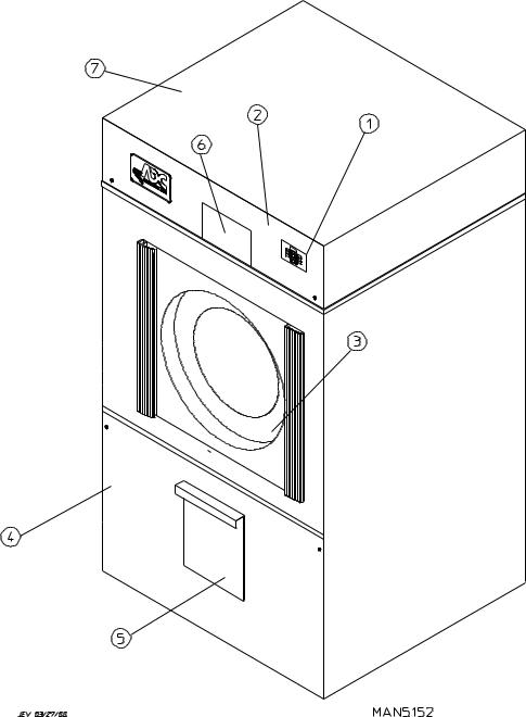
B. COMPONENT IDENTIFICATION
1. Dryer Front View
Illus. No. Description
1Microprocessor Control and Keyboard Panel Assembly (Controls)
2Control (Top Access) Door Assembly
3Main Door Assembly
4 |
Lint Door Assembly |
5Lint Drawer
6Wire Diagram (located behind control door)
7Top Console (module) Assembly
8
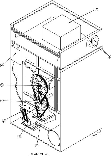
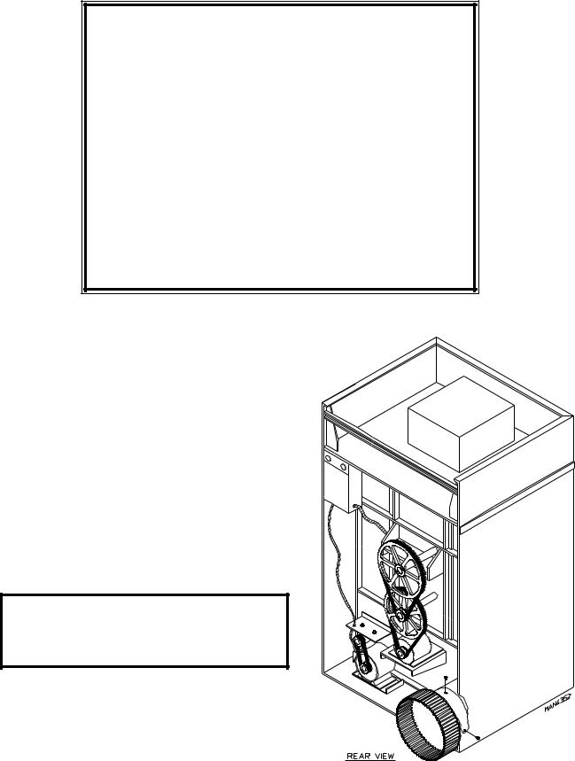
2. Dryer Rear View
Illus. No. Description
1Basket (Drive) MotorAssembly
2Blower Motor MountAssembly
3Impellor (fan/blower)Assembly
4Idler Bearing MountAssembly
5Tumbler Bearing MountAssembly
6* |
Electric Service Relay Box |
7HeatingUnit
8 Data Label and Installation Label
* Electric service connections are made in this box.
9

SECTION III
INSTALLATION PROCEDURES
Installation should be performed by competent technicians in accordance with local and state codes. In the absence of these codes, the installation must conform to applicable AMERICAN NATIONAL STANDARDS or in Canada, the installation must conform to applicable Canadian Standards: CAN/CGA-B149.1-M91 (Natural Gas) or CAN/CGA-B149.2-M91 (L.P. Gas) or LATEST EDITION (for General Installation and Gas Plumbing) or Canadian Electrical Codes Parts 1 & 2 CSA C22.1-1990 or LATEST EDITION (for Electrical Connections).
A. LOCATION REQUIREMENTS
Before installing the dryer, be sure the location conforms to local codes and ordinances. In the absence of such codes or ordinances the location must conform with the National Fuel Gas Code ANSI.Z223.1-LATEST EDITION or applicable Canadian Standards: CAN/CGA-B149.1-M91 (Natural Gas) or CAN/CGA-B149.2- M91 (L.P. Gas) or LATEST EDITION (for General Installation and Gas Plumbing).
1.The dryer must be installed on a sound level floor capable of supporting its weight. It is recommended that carpeting be removed from the floor area that the dryer is to rest on.
2.The dryer must not be installed or stored in an area where it will be exposed to water and/or weather.
3.This dryer is for use in noncombustible locations.
4.Provisions for adequate air supply must be provided as noted in this manual (refer to Fresh Air Supply in
Section D).
5.Clearance provisions must be made from combustible construction as noted in this manual (refer to Dryer Enclosure Requirements in Section C).
6.Provisions must be made for adequate clearances for servicing and for operation as noted in this manual (refer to Dryer Enclosure Requirements in Section C).
7.Dryer must be exhausted to the outdoors (refer to Exhaust Requirements in Section E).
8.Dryer must be located in an area where correct exhaust venting can be achieved as noted in the manual (refer to Exhaust Requirements in Section E).
IMPORTANT: Dryer should be located where a minimum amount of exhaust duct will be necessary.
10
B. UNPACKING and SETTING UP
Remove protective shipping material (i.e., plastic wrap and optional shipping box) from dryer.
IMPORTANT: Dryer must be transported and handled in an upright position at all times.
The dryer can be moved to its final location while still attached to the skid or with the skid removed. To unskid the dryer, locate and remove the four (4) lag bolts securing the base of the dryer to the wooden skid. Two (2) are located at the rear base (remove the back panel for access), and two (2) are located in the bottom of the lint chamber. To remove the two (2) lag bolts located in the lint chamber area, remove the lint drawer and the two (2) Phillips head screws securing lint door in place.
NOTE: Lint door cannot be removed totally from dryer due to a safety chain. The chain is secured to the dryer and door with special tamper proof screws. The safety chain must not be removed or cut from the lint door. Once these lag bolts are off, remove the eight (8) nuts and bolts holding the skid together and take the skid apart. The dryer can now be removed from the skid and set into place.
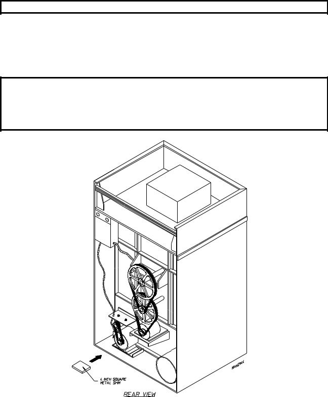
1. Leveling Dryer
a.To level dryer, place 4-inch (10.16 cm) square metal shims (refer to illustration above) or other suitable material under the base pads. It is suggested that the dryer be tilted slightly to the rear.
11
2.The V-belts are disconnected from the basket drive motor for shipping. Reconnect V-belts before starting the dryer.
a.To Reconnect V-belts
1)Remove hardware holding back (belt) guard and remove guard from dryer.
2)Lay one (1) belt into motor sheave (pulley) groove and wind belt into corresponding groove of the idler pulley by rotating the idler pulley by hand. Rotate the idler pulley an extra turn or two to insure that the belt is tracking properly in the motor sheave (pulley) and idler pulley grooves without twisting.
3)Repeat procedure to reconnect the remaining belt.
4)Replace back (belt) guard and hardware.
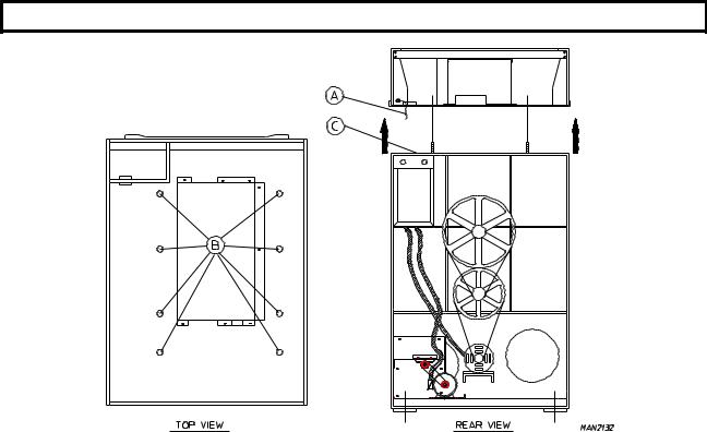
3.If more headroom is needed when moving dryer into position, the top console (module) may be removed.
a.To remove top console (module)
1)Disconnect the ground wire (A) at the Rear Upper Left Hand Corner of Dryer.
2)Remove the six (6) set of nuts and washers (B) holding the console (module) to base.
3)Open the control door and control panel, and disconnect the white 15-pin plug connector (C) located in the base of the control box.
4)Disconnect white plug connector located outside backside of the control box (provides power to heat circuit).
5)Lift the console (module) off of the dryer base.
IMPORTANT: The dryer must be transported and handled in an upright position at all times.
12
4. Exhaust Transition Piece
WARNING
An exhaust duct transition piece is shipped inside of the dryer’s tumbler and MUST be installed on the dryer’s exhaust duct, with the hardware provided, BEFORE location venting is connected to the dryer.
THIS EXHAUST DUCT TRANSITION PIECE
MUST BE INSTALLED FIRST!
Failure to observe this installation requirement may result in damage to the dryer, create a FIRE HAZARD and will VOID the manufacturer’s warranty.
012999JEV-GS/cj |
P/N: 114092 |
a.Inside the tumbler (basket) of this dryer is an Exhaust Transition Piece that must be installed on the outlet of the exhaust before any further venting is connected;
1)Remove the Exhaust Transition Piece from the tumbler (basket) and place it on the exhaust outlet.
2) Using the screws provided, secure the Exhaust Transition Piece to the dryer.
NOTE: It is recommended that this joint be taped as well as ALL other duct joints to prevent moisture and lint from escaping into the building.
13

C. DRYER ENCLOSURE REQUIREMENTS
It is recommended that the rear of the dryer be positioned approximately 3 feet (0.91 meters) from the nearest obstruction (i.e., wall) for ease of installation, maintenance, and service. Bulkheads and partitions should be made of noncombustible materials. The bulkhead facing must not be closed in ALL the way to the top of the dryer. A 2-inch (5.08 cm) clearance is required.
NOTE: Bulkhead facing should not be installed until after dryer is in place. Ceiling area must be located a minimum of 12-inches (30.48 cm) above the top of the dryer.
IMPORTANT: Even though a minimum of only 12-inches (30.48 cm) is required, 18-inches (45.72 cm) or more is suggested for steam dryers and especially in cases where sprinkler heads are over the dryers.
NOTE: When fire sprinkler systems are located above the dryers, a minimum of 18-inches (45.72 cm) above the dryer console (module) is suggested. Dryers may be positioned side wall to side wall however, 1 or 2 inches (2.54 or 5.08 cm) is suggested between dryers (or wall) for ease of installation and maintenance. Allowances must be made for the opening and closing of the control and lint doors.
14
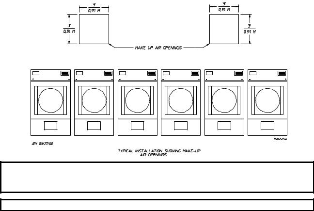
D. FRESH AIR SUPPLY
When the dryer is operating, it draws in room air, heats it, passes this air through the tumbler (basket), and exhausts it out of the building. Therefore, the room air must be continually replenished from the outdoors. If the make-up air is inadequate, drying time and drying efficiency will be adversely affected. Ignition problems and sail switch "fluttering" problems may result, as well as premature motor failure from overheating.
Air supply (make-up air) must be given careful consideration to assure proper performance of each dryer. An unrestricted source of air is necessary for each dryer. An airflow of 2,100 cfm (cubic feet per minute) - 59.4 cmm (cubic meters per minute) - must be supplied to each gas dryer and electric dryer with a 72 Kw oven, 1,700 cfm (48.5 cmm) to each electric dryer with a 60 Kw oven, 2,420 cfm (68.5 cmm) to each electric dryer with a 80 Kw oven, and 2,750 cfm (75.5 cmm) for each steam dryer. As a general rule, an unrestricted air entrance from the outdoors (atmosphere) of a minimum of 3 square feet (0.28 square meters) is required for each gas dryer and 72 Kw electric dryer and a minimum of 5 square feet (0.46 square meters) for each steam dryer.
To compensate for the use of registers or louvers used over the openings, increased by approximately thirty-three percent (33%). Make-up air openings directly near where exhaust vents exit the building.
this make-up air area must be should not be located in an area
It is not necessary to have a separate make-up air opening for each dryer. Common make-up air openings are acceptable. However, they must be set up in such a manner that the make-up air is distributed equally to ALL the dryers.
EXAMPLE: For a bank of six (6) gas dryers, two (2) openings measuring 3 feet by 3 feet (0.91 meters by 0.91 meters (9 square feet [0.84 square meters]) is acceptable.
Allowances must be made for remote or constricting passageways or where dryers are located at excessive altitudes or predominantly low pressure areas.
IMPORTANT: Make-up air must be provided from a source free of dry cleaning solvent fumes. Make-up air that is contaminated by dry cleaning solvent fumes will result in irreparable damage to motors and other dryer components.
NOTE: Component failure due to dry cleaning solvent fumes will VOID THE WARRANTY.
15
E. EXHAUST REQUIREMENTS
1.General Exhaust Duct Work Information
Exhaust duct work should be designed and installed by a qualified professional. Improperly sized duct work will create excessive back pressure which results in slow drying, increased use of energy, overheating of the dryer, and shutdown of the burner by the airflow (sail) switches, burner hi-limits, or basket (tumbler) hi-heat thermostats.
CAUTION: DRYER MUST BE EXHAUSTED TO THE OUTDOORS.
CAUTION: IMPROPERLY SIZED OR INSTALLED EXHAUST DUCT WORK CAN
CREATE A POTENTIAL FIRE HAZARD.
NOTE: When a dryer is exhausted separately, it is recommended that a back draft damper be installed.
NOTE: When dryers are exhausted into a multiple (common) exhaust line, each dryer must be supplied with a back draft damper.
The exhaust duct work should be laid out in such a way that the duct work travels as directly as possible to the outdoors with as few turns as possible. Single or independent dryer venting is recommended.
When single dryer venting is used, the duct work from the dryer to the outside exhaust outlet should not exceed 20 feet (6.1 meters). In the case of multiple (common) dryer venting, the distance from the last dryer to the outside exhaust outlet should not exceed 20 feet (6.1 meters). The shape of the duct work is not critical so long as the minimum cross section area is provided. It is suggested that the use of 90º turns in ducting be avoided; use 30º or 45º angles instead. The radius of the elbows should preferably be 1-1/2 times the diameter of the duct. Excluding basket and dryer elbow connections or elbows used for outside protection from the weather, no more than two (2) elbows should be used in the exhaust duct run. If more than two (2) elbows are used, the cross section area of the duct work must be increased in proportion to number of elbows added.
ALL duct work should be smooth inside with no projections from sheet metal screws or other obstructions which will collect lint. When adding ducts, the ducts to be added should overlap the duct to which it is connected. ALL duct work joints must be taped to prevent moisture and lint from escaping into the building. Additionally, inspection doors should be installed at strategic points in the exhaust duct work for periodic inspection and clean-out of lint from the duct work.
IMPORTANT: Exhaust back pressure measured by a manometer at the dryer exhaust duct area must not exceed 0.3 inches of water column (0.74 millibars).
NOTE: Where the exhaust duct work passes through a wall, ceiling, or roof made of combustible materials, the opening must be 2-inches (5.08 cm) larger (all the way around) than the duct. The duct must be centered within this opening.
16
a.Outside Duct Work Protection
1)To protect the outside end of horizontal duct work from the weather, a 90° elbow bent downward should be installed where the exhaust exits the building. If the exhaust duct work travels vertically up through the roof, it should be protected from the weather by using a 180° turn to point the opening downward. In either case, allow at least twice the diameter of the duct between the duct opening and the nearest obstruction.
IMPORTANT: DO NOT use screens or caps on the outside of opening of exhaust duct work.
2.Single Dryer Venting
a.Horizontal Venting
Where possible, it is suggested to provide a separate exhaust duct for each dryer. The exhaust duct should be laid out in such a way that the duct work travels as directly as possible to the outdoors with as few turns as possible. It is suggested that the use of 90° turns in ducting be avoided; use 30° or 45° angles instead. The shape of the exhaust duct work is not critical so long as the minimum cross section area is provided.
IMPORTANT: Minimum duct size for a gas dryer and 60 Kw or 72 Kw electric dryer is 14-inches (35.56 cm) for a round duct or 12-1/2" by 12-1/2" (31.75 cm by 31.75 cm) for a square duct. The minimum duct size for a steam dryer or 80 Kw electric dryer is 16-inches (40.64 cm) for a round duct or 14-1/2" by 14-1/2" (36.83 cm by 36.83 cm) for a square duct. DUCT SIZE MUST NOT BE REDUCED
ANYWHERE DOWN STREAM OF THE DRYER.
IMPORTANT: Exhaust back pressure measured by a manometer at each basket (tumbler) exhaust duct area should not exceed 0.3 inches of water column (0.74 millibars).
17
 Loading...