

Page 1
AD-115 Parts Manual
24 VAC Phase 5
1994 thru 2000
American Dryer Corporation
88 Currant Road
Fall River MA 02720-4781
Telephone: (508) 678-9000 / Fax: (508) 678-9447
E-mail: techsupport@amdry.com
071594
071995
060297MFM/tf ADC Part No. 450145
Page 2

Retain This Manual In A Safe Place For Future Reference
American Dryer Corporation products embody advanced concepts in engineering, design, and safety. If this product is
properly maintained, it will provide many years of safe, efficient, and trouble-free operation.
ONLY qualified technicians should service this equipment.
OBSERVE ALL SAFETY PRECAUTIONS displayed on the equipment or specified in the installation/operator's manual
included with the dryer.
The following FOR YOUR SAFETY caution must be posted near the dryer in a prominent location.
FOR YOUR SAFETY
Do not store or use gasoline or
other flammable vapors or liquids
in the vicinity of this or any other
appliance.
We have tried to make this manual as complete as possible and hope you will find it useful. ADC reserves the right to make
changes from time to time, without notice or obligation, in prices, specifications, colors, and material, and to change or
discontinue models.
POUR VOTRE SÉCURITÉ
Ne pas entreposer ni utiliser dessence
ni dautres vapeurs ou liquides
inflammables dans le voisinage de cet
appareil ou de yout autre appareil.
Important
For your convenience, log the following information:
DATE OF PURCHASE ____________________________ MODEL NO. __________________________________________
DISTRIBUTORS NAME ___________________________________________________________________________________
Serial Number(s) ________________________________________________________________________________________
________________________________________________________________________________________
AD-115
________________________________________________________________________________________
Replacement parts can be obtained from your distributor or the ADC factory. When ordering replacement parts from the
factory, you can FAX your order to ADC at (508) 678-9447 or telephone your orders directly to the ADC Parts Department at
(508) 678-9000. Please specify the dryer model number and serial number in addition to the description and part number, so
that your order is processed accurately and promptly.
The illustrations on the following pages may not depict your particular dryer exactly. The illustrations are a composite from
the various dryer models. Be sure to check descriptions of the parts thoroughly before ordering.
IMPORTANT NOTE TO PURCHASER
Information must be obtained from your local gas supplier on the instructions
to be followed if the user smells gas. These instructions must be posted in a
prominent location near the dryer.
Page 3

Table of Contents
Control Door Assembly ....................................................................................................................................... 3
Microprocessor Control Panel Assembly ............................................................................................................ 4
Control Box Assembly ......................................................................................................................................... 5
Dual Timer Control Panel Assembly................................................................................................................ 6, 7
Dual Timer Control Box Assembly .................................................................................................................. 8, 9
Front Panel Main Door Assembly ................................................................................................................10, 11
Main Door Switch Assembly
for Models mfd. as of December 15, 1994 ........................................................................................... 12
Main Door Switch Assembly
for Models mfd. prior to December 15, 1994 ...................................................................................... 13
Lint Drawer/Lint Drawer Switch Box Assemblies
for Models mfd. between March 28, 1995 through September 1, 1999 ......................................... 14
Lint Drawer/Lint Drawer Switch Box Assemblies
for Models mfd. prior to March 28, 1995 and after September 1, 1999 ......................................... 15
Drop Lint Door Assembly .................................................................................................................................. 16
Microprocessor Temperature Sensor Bracket Assembly .................................................................................. 17
Non-Microprocessor Temperature Sensor Bracket Assembly.................................................................... 18, 19
Tumbler (Basket)/Support Assemblies......................................................................................................... 20, 21
Tumbler Bearing Mount Assembly .............................................................................................................. 22, 23
Idler Bearing Mount Assembly .................................................................................................................... 24, 25
Totally Enclosed, Fan-Cooled (T.E.F.C.) Tumbler (Basket) Motor Mount Assembly ................................. 26, 27
Blower Motor Mount Assembly
for Gas Models ONLY ....................................................................................................................... 28, 29
Blower Motor Mount Assembly
for Electric Models ONLY ................................................................................................................ 30, 31
Blower Motor Mount Assembly
for Steam Models ONLY ................................................................................................................... 32, 33
Direct Spark Ignition (DSI) Burner Assembly
for Gas Models ONLY ....................................................................................................................... 34, 35
Direct Spark Ignition (DSI) Module Mount Assembly
for Gas Models ONLY ............................................................................................................................. 36
Sail Switch Assembly ......................................................................................................................................... 37
Electric Oven Assembly .............................................................................................................................. 38, 39
Electric Oven Relay Box Assembly
208/240 VAC 3ø 50/60 Hz ..................................................................................................................... 40
Electric Oven Relay Box Assembly
380/416/480 VAC 3ø 50/60 Hz ............................................................................................................. 41
Steam Damper Assembly ............................................................................................................................ 42, 43
Microprocessor Reversing Control Box Assembly
for Gas, Steam, and Electric Models mfd. prior to March 29, 1995 ................................................ 44
Microprocessor Reversing Contactor Mounting Panel Assembly
for Electric Models mfd. as of March 29, 1995 ................................................................................... 45
Dual Timer Reversing Control Box Assembly
for Gas, Steam, and Electric Models mfd. prior to March 29, 1995 ................................................ 46
Dual Timer Reversing Relay Mounting Panel Assembly
for Gas, Steam, and Electric Models mfd. as of March 29, 1995 ...................................................... 47
Extended Back Guard Assembly
for ALL 60 Hz Models mfd. as of January 26, 1995
for ALL 50 Hz Models mfd. as of January 9, 1995 ............................................................................. 48
Extended Back Guard Assembly
for ALL 60 Hz Models mfd. prior to January 26, 1995
for ALL 50 Hz Models mfd. prior to January 9, 1995 ........................................................................ 49
Page 4

Step Down Transformer Usage Listing ............................................................................................................. 50
Direct Spark Ignition (DSI) Burner Assembly Specifications ........................................................................... 51
60 Kw Electric Oven Component Application Charts ....................................................................................... 52
72 Kw and 80 Kw Electric Oven Component Application Charts .................................................................... 53
Electric Oven Power Distribution
for 60 Kw 208/240 VAC Microprocessor Models mfd. as of April 11, 1995 .................................. 54
Electric Oven Power Distribution
for 60 Kw 380/416/480 VAC Microprocessor Models mfd. as of April 11, 1995........................... 55
Electric Oven Power Distribution
for 60 Kw 208/240 VAC Dual Timer Models mfd. as of April 11, 1995 ........................................... 56
Electric Oven Power Distribution
for 60 Kw 380/416/480 VAC Dual Timer Models mfd. as of April 11, 1995 ................................... 57
Electric Oven Power Distribution
for 60 Kw 208/240 VAC Models mfd. prior to April 11, 1995 ........................................................... 58
Electric Oven Power Distribution
for 60 Kw 380/416/480 VAC Models mfd. prior to April 11, 1995 ................................................... 59
Electric Oven Power Distribution
for 72 Kw 208/240 VAC Microprocessor Models mfd. as of April 11, 1995 .................................. 60
Electric Oven Power Distribution
for 72 Kw 600 VAC Microprocessor Models mfd. as of April 11, 1995 .......................................... 61
Electric Oven Power Distribution
for 72 Kw 380/416/480 VAC Microprocessor Models mfd. as of April 11, 1995........................... 62
Electric Oven Power Distribution
for 72 Kw 208/240 VAC Dual Timer Models mfd. as of April 11, 1995 ........................................... 63
Electric Oven Power Distribution
for 72 Kw 380/416/480 VAC Dual Timer Models mfd. as of April 11, 1995 ................................... 64
Electric Oven Power Distribution
for 72 Kw 208/240 VAC Models mfd. prior to April 11, 1995 ........................................................... 65
Electric Oven Power Distribution
for 72 Kw 380/416/480 VAC Models mfd. as of April 11, 1995 ........................................................ 66
Electric Oven Power Distribution
for 80 Kw 208/240 VAC Microprocessor Models mfd. as of April 11, 1995 .................................. 67
Electric Oven Power Distribution
for 80 Kw 380/416/480 VAC Microprocessor Models mfd. as of April 11, 1995........................... 68
Electric Oven Power Distribution
for 80 Kw 208/240 VAC Dual Timer Models mfd. as of April 11, 1995 ........................................... 69
Electric Oven Power Distribution
for 80 Kw 380/416/480 VAC Dual Timer Models mfd. as of April 11, 1995 ................................... 70
Electric Oven Power Distribution
for 80 Kw 208/240 VAC Models mfd. prior to April 11, 1995 ........................................................... 71
Electric Oven Power Distribution
for 80 Kw 380/416/480 VAC Models mfd. prior to April 11, 1995 ................................................... 72
Electric Oven Wiring
for
ALL 208/240 VAC Models mfd. as of April 11, 1995 ................................................................... 73
Electric Oven Wiring
for ALL 380/416/480 VAC Models mfd. as of April 11, 1995 ............................................................ 74
Electric Oven Element Structure
for 60 Kw 208/240 VAC Models mfd. prior to April 11, 1995 ........................................................... 75
Electric Oven Element Structure
for 60 Kw 380/416/480 VAC Models mfd. prior to April 11, 1995 ................................................... 76
Additional Parts Available .................................................................................................................................. 77
Page 5
Telephone: (508) 678-9000
Fax: (508) 678-9447
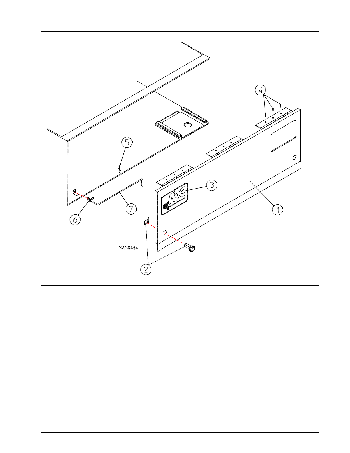
Control Door Assembly
3
Illus. No. Part No. Qty. Description
1 850491* 1 Control Door Assembly ONLY
2 160005 2 Spring Turn Latch (2-piece)
3 112360 1 ADC Logo ONLY
4 150309 9 #10-16 x 1/2” Hex Head TEK Crimptite Screw
5 102600 1 Control Door Support Rod Catch
6 102601 1 Control Door Rod Retainer Clip
7 102505 1 Control Door Support Rod
* Specify color when ordering.
(for gas models and electric models Only)
850492 1 Stainless Steel Control Door Assembly ONLY
(for gas models and electric models Only)
850489* 1 Short Control Door ONLY
(for steam models Only)
850490 1 Stainless Steel Short Control Door ONLY
(for steam models Only)
870011 1 Logo Double Tape Kit
Page 6
4
American Dryer Corporation
88 Currant Road / Fall River, MA 02720-4781
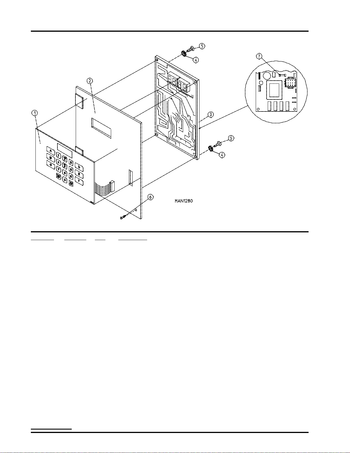
Microprocessor Control Panel Assembly
Illus. No. Part No. Qty. Description
1 112535 1 OPL English Keyboard Label Assembly
112276 1 OPL Stick-on Labels (English Only) ... Not Illustrated
112275 1 OPL Stick-on Labels (Spanish, Italian, and Hebrew) ... Not Illustrated
112277 1 3-Language OPL Stick-on Labels
(English, Spanish, and Hebrew) ... Not Illustrated
112278 1 5-Language OPL Stick-on Labels
(Italian, Dutch, French, German, and Chinese) ... Not Illustrated
2 880836 1 Microprocessor Control Panel ONLY
801260 1 Microprocessor Control Panel ONLY with Battery Bracket
801215 1 Microprocessor Control Panel Assembly Complete
(includes illus. nos. 1 through 5 and 7)
801214 1 Microprocessor Control Panel Assembly Complete with Battery Option
(includes illus. nos. 1 through 5 and 7)
3 137231 1 Phase 5 OPL Reversing Controller ONLY
824998 1 Phase 5 Battery Clip
4 153010 2 #6 Star Washer
5 150005 2 #6-32 x 1/4” Phillips Round Head Machine Screw
6 150309 1 #10-16 x 1/2” Hex Head TEK Crimptite Screw
(for models mfd. as of March 1, 1994)
160005 1 Spring Turn Latch (2-piece)
For Models mfd. prior to March 1, 1994
7 136048 1 1/8-Amp (slo blo) Fuse ONLY
IMPORTANT : Check label on computer chip to verify correct part number for controller.
Page 7
Telephone: (508) 678-9000
Fax: (508) 678-9447
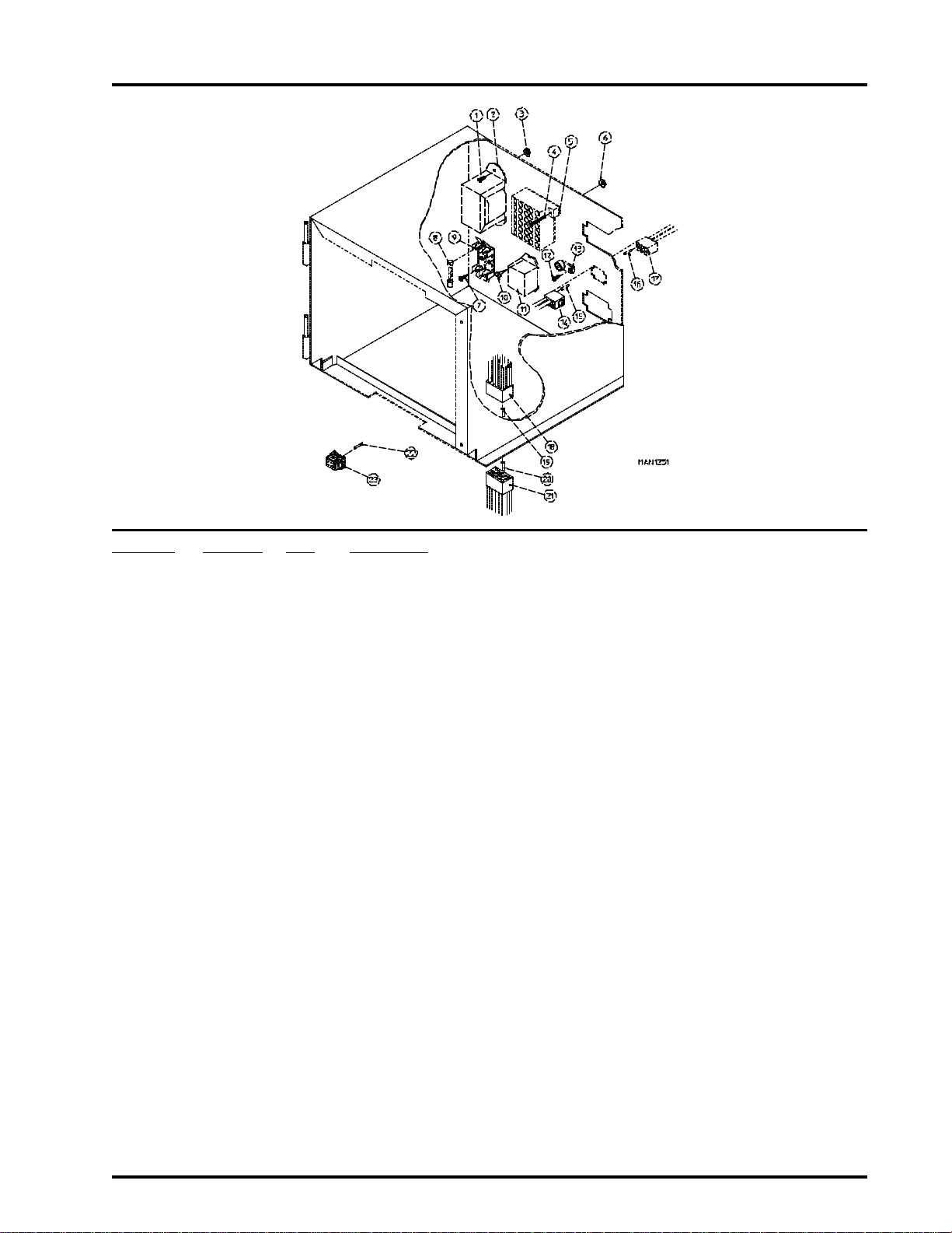
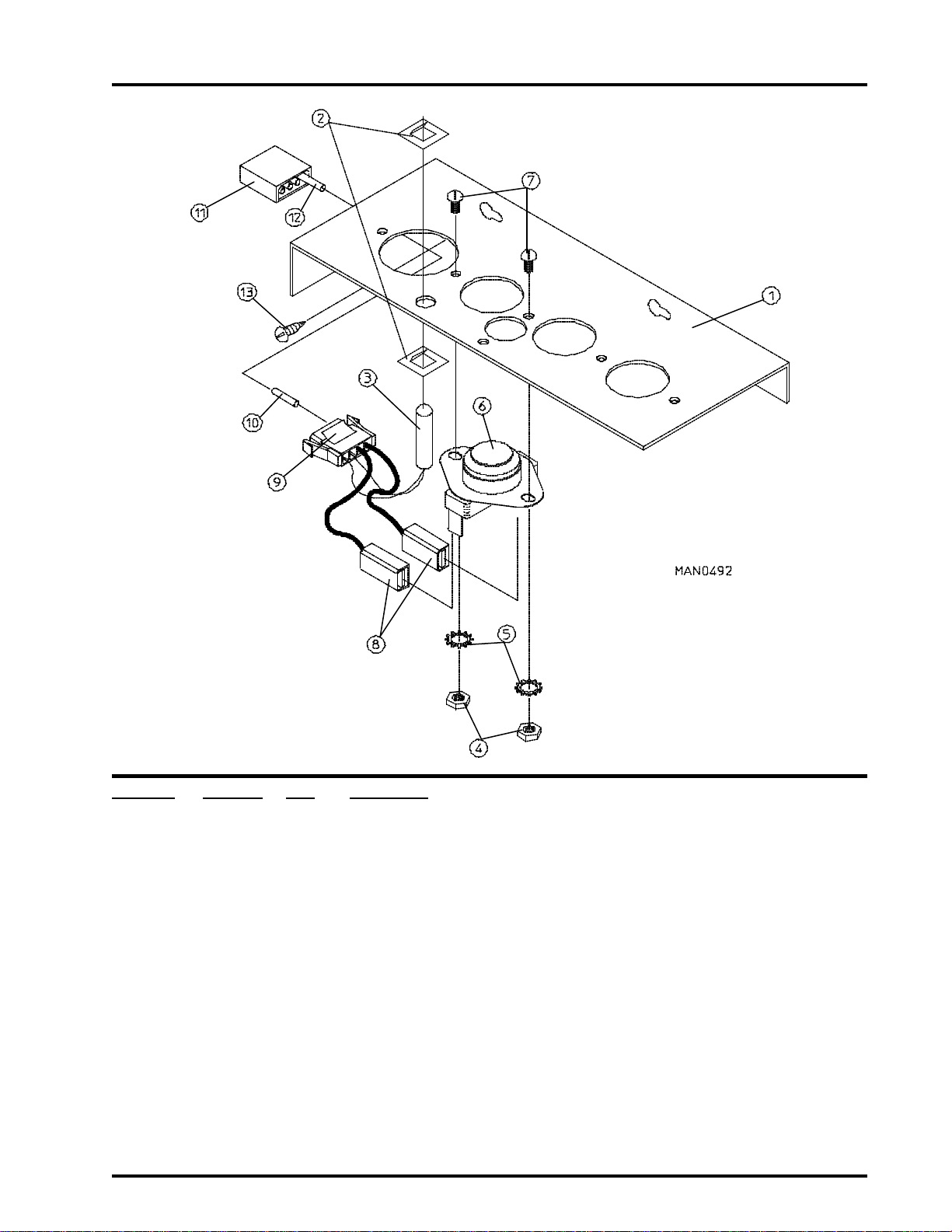
Control Box Assembly
5
Illus. No. Part No. Qty. Description
1 150100 2 #8-32 x 1/2” Phillips Round Head Machine Screw
2 141403 1 24 VAC Transformer - 50/60 Hz
3 151001 2 #8-32 Pal Nut
4 150002 2 #6-32 x 1” Phillips Round Head Machine Screw
5 120715 1 30-Position Terminal Block
6 151000 2 #6-32 Pal Nut
7 150102 2 or 3 #8 x 3/8” Phillips Pan Head TEK Screw
8 136057 2 1/2-Amp (slo blo) Fuse ONLY
182453 1 6-Amp Fuse (for electric models Only)
9 136008 2 or 3 Fuse Block/Strip ONLY
10 150309 2 #10-16 x 1/2” Hex Head TEK Crimptite Screw
11 131932 1 24 VAC Relay (for electric models Only)
12 150309 1 #10-16 x 1/2” Hex Head TEK Crimptite Screw
13 121010 1 L-70 Ground Lug
14 122631 1 6-Pin Socket Connector ONLY
15 122705 * Socket Terminal ONLY
16 122704 * Pin Terminal ONLY
17 122630 1 6-Pin Connector ONLY
137025 1 6/15-Position Strain Relief ... Not Illustrated
18 122625 1 15-Pin Connector ONLY
19 122704 12 Pin Terminal ONLY
20 122705 12 Socket Terminal ONLY
21 122626 1 15-Pin Socket Connector ONLY
22 122706 11 Microprocessor Socket ONLY
23 122641 1 15-Pin Microprocessor Connector ONLY
-- 122800 1 Microprocessor (female) Pin Extraction Tool
-- 122801 1 Pin/Socket Extraction Tool
* As required (either 2 or 3).
Page 8
6
American Dryer Corporation
88 Currant Road / Fall River, MA 02720-4781
Dual Timer Control Panel Assembly
Page 9

Telephone: (508) 678-9000
Fax: (508) 678-9447
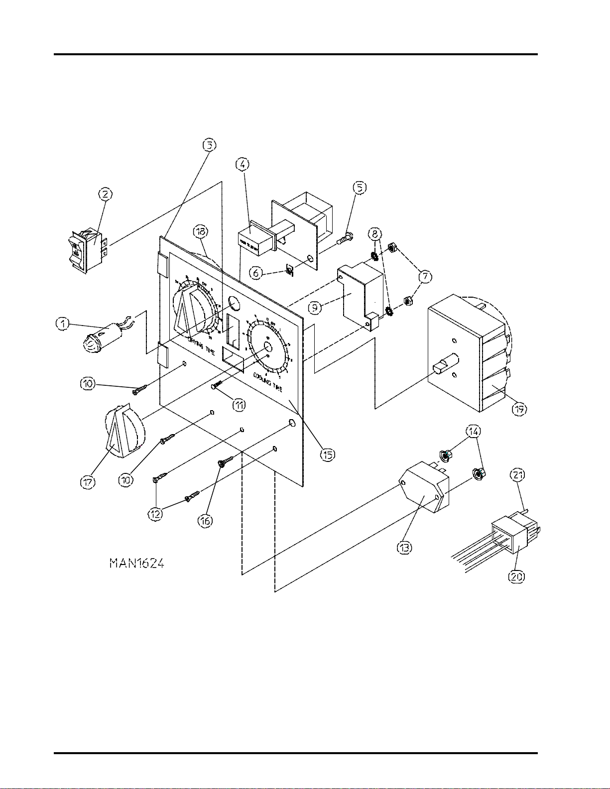
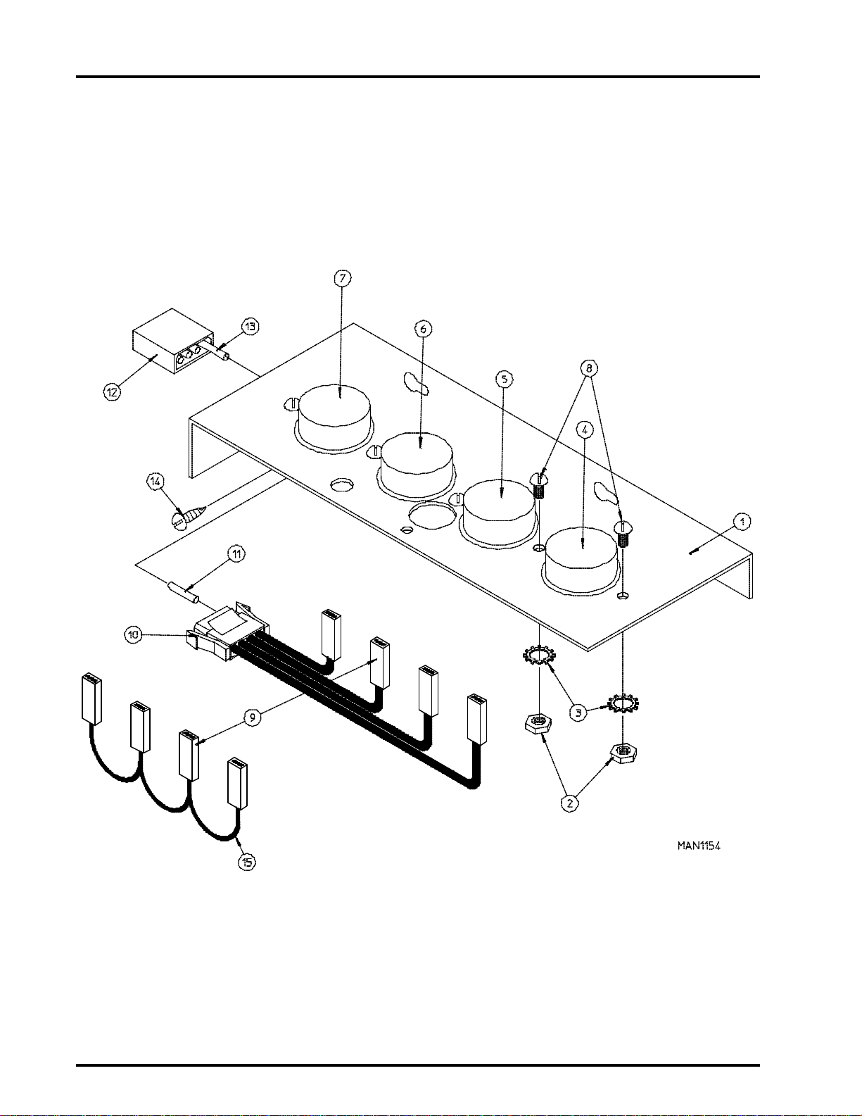
Dual Timer Control Panel Assembly
Illus. No. Part No. Qty. Description
1 123005 1 Red Indicator Light - 24 VAC
2 122400 1 Rocker Heat Selector Switch
3 880838 1 Dual Timer Control Panel Assembly Complete - 24 VAC
(includes illus. nos. 1 through 15 and 17 through 21)
880837 1 Dual Timer Control Panel ONLY
4 131917 1 Push to Start Relay - 24 VAC
5 150207 2 #10-24 x 1/2” Phillips Pan Head Machine Screw
6 154001 2 #10-24 Speed Nut
7 152000 2 #6-32 Hex Nut
8 153010 2 #6 Star Washer
9 120730 1 30-Position Terminal Block
(for models mfd. as of May 2, 1993)
120713 1 18-Position Terminal Block
(for models mfd. prior to May 2, 1993)
10 153565 2 #6-32 x 1” Clinch Stud
11 150110 4 #8-32 x 1/4” Phillips Round Head Machine Screw
12 153560 2 #6-32 x 1/2” Clinch Stud
13 131931 1 Dual Timer Relay - 24 VAC
14 151000 2 #6-32 Pal Nut
15 112050 1 Dual Timer Label ONLY
16 150309 1 #10-16 x 1/2” Hex Head TEK Crimptite Screw
(for models mfd. as of March 1, 1994)
160005 1 Spring Turn Latch (2-piece)
For Models mfd. prior to March 1, 1994
17 124103 2 Arrow Timer Knob
18 124025 1 60 Minute Timer - 24 VAC
19 124030 1 15 Minute Timer - 24 VAC
20 122602 1 9-Pin Connector ONLY
21 122700 7 Pin Terminal ONLY
-- 122801 1 Pin/Socket Extraction Tool
7
Page 10
8
American Dryer Corporation
88 Currant Road / Fall River, MA 02720-4781
Dual Timer Control Box Assembly
Page 11

Telephone: (508) 678-9000
Fax: (508) 678-9447
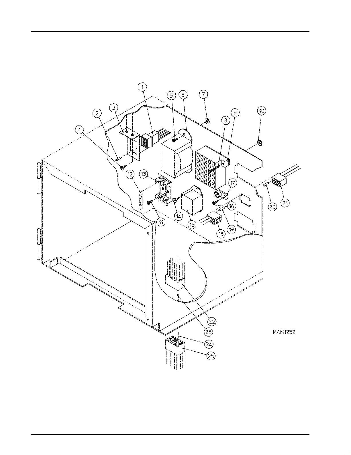
Dual Timer Control Box Assembly
Illus. No. Part No. Qty. Description
1 122603 1 9-Pin Socket Connector
2 122701 7 Socket Terminal ONLY
122801 1 Pin/Socket Extraction Tool
3 315010 1 9-Pin Connector Bracket
4 150300 2 #10 x 1/2” Hex Washer TEK Screw
5 150100 2 #8-32 x 1/2” Phillips Round Head Machine Screw
6 132070 1 24 VAC Transformer - 50/60 Hz
7 151001 2 #8-32 Pal Nut
8 150002 2 #6-32 x 1” Phillips Round Head Machine Screw
9 120715 1 30-Position Terminal Block
10 151000 2 #6-32 Pal Nut
11 150301 2 or 3 #8-18 x 7/16” Phillips Pan Head TEK Screw
12 136057 2 1/2-Amp (slo blo) Fuse ONLY
182453 1 6-Amp Fuse (for electric models Only)
13 136008 2 or 3 Fuse Block/Strip ONLY
14 150309 2 #10-16 x 1/2” Hex Head TEK Crimptite Screw
15 131932 1 24 VAC Relay (for electric models Only)
16 150309 1 #10-16 x 1/2” Hex Head TEK Crimptite Screw
17 121010 1 L-70 Ground Lug
18 122631 1 6-Pin Socket Connector ONLY
19 122705 2 Socket Terminal ONLY
20 122704 2 Pin Terminal ONLY
21 122630 1 6-Pin Connector ONLY
137025 1 6/15-Position Strain Relief ... Not Illustrated
22 122625 1 15-Pin Connector ONLY
23 122704 10 Pin Terminal ONLY
24 122705 10 Socket Terminal ONLY
25 122626 1 15-Pin Socket Connector ONLY
-- 122801 1 Pin/Socket Extraction Tool
9
Page 12
10
American Dryer Corporation
88 Currant Road / Fall River, MA 02720-4781
Front Panel Main Door Assembly
Page 13

Telephone: (508) 678-9000
Fax: (508) 678-9447
Front Panel Main Door Assembly
Illus. No. Part No. Qty. Description
1 800349* 1 Right Hand Front Panel Assembly (formed rings)
(includes illus. nos. 1, 4, and 5)
850751 1 Stainless Steel Right Hand Front Panel Assembly
(includes illus. nos. 1, 4, and 5)
882110 1 Right Hand Front Panel Assembly Panels with Welded Rings
(includes illus. nos. 1, 4, and 5)
2 150309 15 #10-16 x 1/2” Hex Head TEK Crimptite Screw
3 150412 12 #10-16 x 3/4” Phillips Round Head Crimptite Screw
4 170340 3 3-1/2” Stainless Steel Striker Pad
5 154200 6 5/32” Pop Rivet
6 102308 1 Door Gasket ONLY (94” length)
7 102210 1 20-7/16” Door Glass ONLY
170730 1 Glass Adhesive (10.3 oz. cartridge)
8 150401 3 #10-24 x 1-1/4” Phillips Taptite Screw
9 306801 6 Magnet Keeper ONLY
10 102100 6 1” x 1” x 1/4” Main Door Magnet ONLY
11 150309 9 #10-16 x 1/2” Hex Head TEK Crimptite Screw
12 180151 1 35” Granite Main Door Handle ONLY
13 800265* 1 Main Door Assembly Complete with Granite Handle
(includes illus. nos. 6 through 13)
800266 1 Stainless Steel Main Door Assembly Complete with Granite Handle
(includes illus. nos. 6 through 13)
800122* 1 Main Door Assembly with Glass Gasket ONLY
(includes illus. nos. 6, 7, and 13)
800123 1 Stainless Steel Main Door Assembly with Glass Gasket ONLY
(includes illus. nos. 6, 7, and 13)
14 150430 10 #10 x 1/2” Phillips Self Drilling Screw
15 180156 1 35” Granite Main Door Hinge Block ONLY
11
* Specify color when ordering.
Page 14
12
American Dryer Corporation
88 Currant Road / Fall River, MA 02720-4781
Main Door Switch Assembly
for Models mfd. as of December 15, 1994
Illus. No. Part No. Qty. Description
1 821098 1 Main Door Switch Assembly Complete
(includes illus. nos. 1 through 4 and 6)
821097 1 Main Door Switch Bracket Assembly ONLY
102405 1 Main Door Switch Actuator ONLY
2 150309 2 #10-16 x 1/2” Hex Head TEK Crimptite Screw
3 102405 1 Main Door Switch Actuator ONLY
4 137005 1 Main Door Switch ONLY
5 121028 2 1/4” x .032 Insulated Terminal ONLY
6 180156 1 35” Granite Main Door Hinge Block ONLY
7 122705 2 Socket Terminal ONLY
8 122626 1 15-Pin Socket Connector ONLY
Page 15
Telephone: (508) 678-9000
Fax: (508) 678-9447
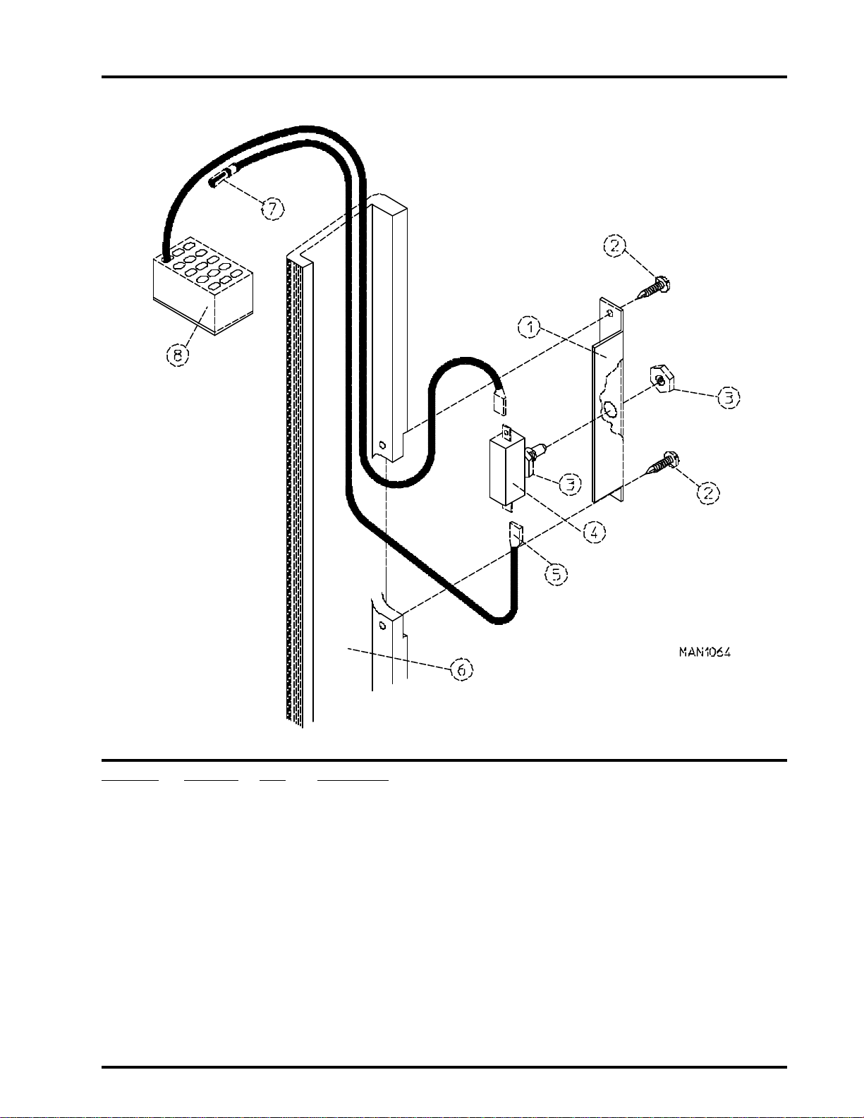
Main Door Switch Assembly
for Models mfd. prior to December 15, 1994
13
Illus. No. Part No. Qty. Description
1 313208 1 Main Door Switch Bracket ONLY
2 150309 2 #10-16 x 1/2” Hex Head TEK Crimptite Screw
3 152003 2 3/8-32 x 1/2” x 1/16” Door Switch Nut
4 136995 1 Door Switch ONLY
5 121028 2 1/4” x .032 Insulated Terminal ONLY
6 180156 1 35” Granite Main Door Hinge Block ONLY
7 122705 2 Socket Terminal ONLY
8 122626 1 15-Pin Socket Connector ONLY
(for models mfd. as of June 26, 1992)
137006 1 Door Switch ONLY
(for models mfd. prior to June 26, 1992)
(for models mfd. as of March 8, 1993)
180155 1 35” Gray Main Door Hinge Block ONLY
(for models mfd. prior to March 8, 1993)
Page 16
14
American Dryer Corporation
88 Currant Road / Fall River, MA 02720-4781
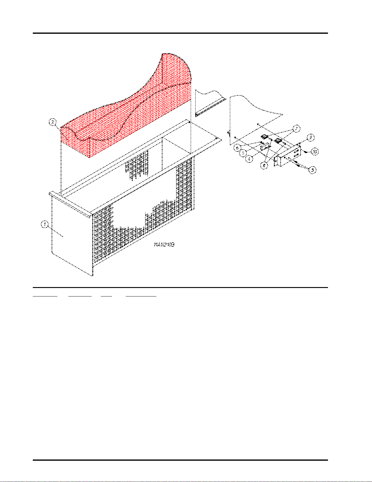
Lint Drawer/Lint Drawer Switch Box Assemblies
for Models mfd. between March 28, 1995 through September 1, 1999
Illus. No. Part No. Qty. Description
1 850597* 1 Lint Drawer Assembly with Safety Switch Actuator Complete
850598 1 Stainless Steel Lint Drawer Assembly with Safety Switch
Actuator Complete
2 820017 1 Lint Screen Assembly ONLY
3 153562 2 #8-32 x 3/4” Clinch Stud
4 136992 1 Lint Drawer Switch ONLY
5 153000 2 #8 Steel Burr
6 152001 2 #8-32 Hex Nut
7 122605 2 4-Pin Socket (female) Connector ONLY
8 122701 4 Socket Terminal ONLY
122801 1 Pin/Socket Extraction Tool
9 821119 1 Lint Drawer Switch Assembly Complete
(includes illus. nos. 3 through 9)
821116 1 Lint Drawer Switch Mounting Bracket Assembly ONLY
(includes illus. nos. 3 and 4)
332348 1 Lint Drawer Switch Mounting Bracket ONLY
10 150309 2 #10-16 x 1/2” Hex Head TEK Crimptite Screw
* Specify color when ordering.
Page 17
Telephone: (508) 678-9000
Fax: (508) 678-9447
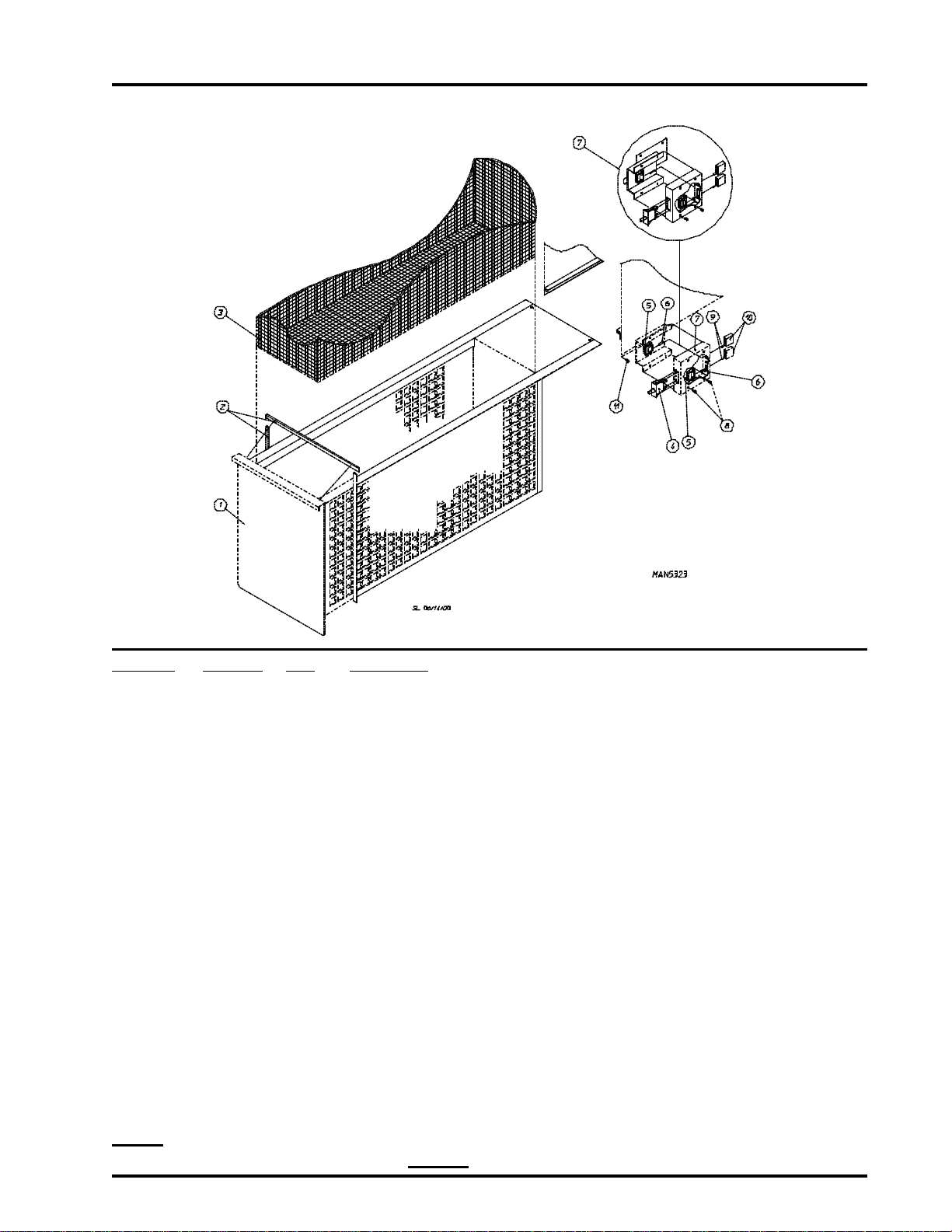
Lint Drawer/Lint Drawer Switch Box Assemblies
for Models mfd. prior to March 28, 1995 and after September 1, 1999
15
Illus. No. Part No. Qty. Description
1* 880871 1 Lint Drawer Assembly Complete
(includes illus. nos. 1 and 2)
2 117602 5 Gasket (sold by the foot)
3 820017 1 Lint Screen Assembly ONLY
4 122116 1 Lint Drawer Switch ONLY
5 122605 2 4-Pin Socket (female) Connector ONLY
6 122701 4 Socket Terminal ONLY
122801 1 Pin/Socket Extraction Tool
7 800264 1 Lint Drawer Switch Box Assembly Complete
(includes illus. nos. 4 through 7)
800478 1 Guarded Lint Drawer Switch Assembly
(includes illus. nos. 4 through 7)
For Models mfd. as of September 1, 1999
304034 1 Lint Drawer Switch Box ONLY
8 150301 2 #8-18 x 7/16” Phillips Pan Head TEK Screw
9 122700 4 Pin Terminal ONLY
10 122604 2 4-Pin Connector ONLY
11 150301 2 #8-18 x 7/16” Phillips Pan Head TEK Screw
* Specify color when ordering.
NOTE: Gasket used on models mfd. prior to December 1, 1994. For current gasket placement refer to
Drop Lint Door Assembly on page 16.
Page 18
16
American Dryer Corporation
88 Currant Road / Fall River, MA 02720-4781
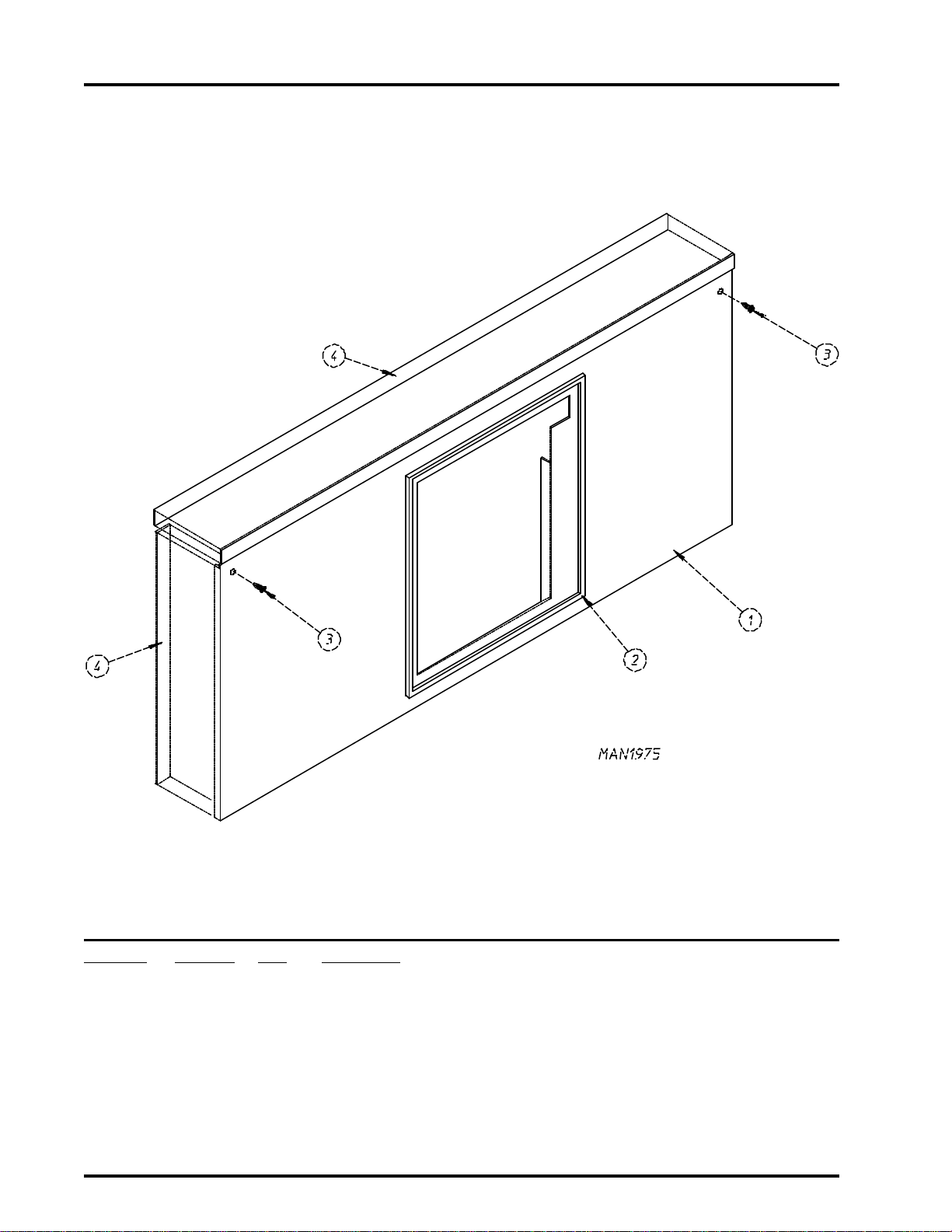
Drop Lint Door Assembly
Illus. No. Part No. Qty. Description
1 880870* 1 Drop Lint Door Assembly
(includes illus. nos. 1, 2, and 4)
880872 1 Stainless Steel Drop Lint Door Assembly
(includes illus. nos. 1, 2, and 4)
2 117602 5 Gasket (sold by the foot)
3 150309 5 #10-16 x 1/2” Hex Head TEK Crimptite Screw
4 117600 5 Noise Suppressor Tape (sold by the foot)
* Specify color when ordering.
Page 19
Telephone: (508) 678-9000
Fax: (508) 678-9447
Microprocessor Temperature Sensor Bracket Assembly
17
Illus. No. Part No. Qty. Description
1 820022 1 Temperature Sensor Bracket Assembly Complete
2 154007 2 1/4” Tinnerman Push-On Fastener
3 880251 1 1/4” Temperature Sensor Probe Assembly
4 152000 2 #6-32 Hex Nut
5 153010 2 #6 Star Washer
6 130112 1 225º Large Automatic Reset Thermostat ONLY
7 150005 2 #6-32 x 1/4” Phillips Round Head Machine Screw
8 121028 2 1/4” x .032 Insulated Terminal ONLY
9 122605 1 4-Pin Socket (female) Connector ONLY
10 122701 4 Socket Terminal ONLY
11 122604 1 4-Pin Connector ONLY
12 122700 4 Pin Terminal ONLY
13 150301 2 #8-18 x 7/16” Phillips Pan Head TEK Screw
(includes illus. nos. 1 through 10)
331295 1 Temperature Sensor Bracket ONLY
(includes illus. nos. 2, 3, 8, 9, and 10)
122801 1 Pin/Socket Extraction Tool
Page 20
18
American Dryer Corporation
88 Currant Road / Fall River, MA 02720-4781
Non-Microprocessor Temperature Sensor Bracket Assembly
Page 21

Telephone: (508) 678-9000
Fax: (508) 678-9447
Non-Microprocessor Temperature Sensor Bracket Assembly
Illus. No. Part No. Qty. Description
1 801404 1 Non-Microprocessor Sensor Bracket Assembly Complete
(includes illus. nos. 1 through 11 and 15)
For Gas and Electric Models ONLY
880839 1 Non-Microprocessor Sensor Bracket Assembly Complete
(includes illus. nos. 1 through 11 and 15)
For Steam Models ONLY
331295 1 Universal Sensor Bracket ONLY
2 152000 5 #6-32 Hex Nut
3 153010 5 #6 Star Washer
4 130101 1 180º Large Thermostat
(for gas and electric models Only)
130104 1 215º Large Thermostat
(for steam models Only)
5 130109 1 140º Large Thermostat
(for gas and electric models Only)
130100 1 150º Large Thermostat
(for steam models Only)
6 130107 1 160º Large Thermostat
(for gas and electric models Only)
130101 1 180º Large Thermostat
(for steam models Only)
7 130112 1 225º Large Thermostat (for ALL models)
8 150005 5 #6-32 x 1/4” Phillips Round Head Machine Screw
9 121028 8 1/4” x .032 Insulated Terminal ONLY
10 122605 1 4-Pin Socket (female) Connector ONLY
840062 1 Sensor (4) Bracket Harness Assembly
(includes illus. nos. 9, 10, and 11)
11 122701 4 Socket Terminal ONLY
12 122604 1 4-Pin Connector ONLY
13 122700 4 Pin Terminal ONLY
122801 1 Pin/Socket Extraction Tool
14 150301 2 #8-18 x 7/16” Phillips Pan Head TEK Screw
15 831701 1 Sensor Jumper (4) ONLY
19
Page 22
20
American Dryer Corporation
88 Currant Road / Fall River, MA 02720-4781
Tumbler (Basket)/Support Assemblies
Page 23

Telephone: (508) 678-9000
Fax: (508) 678-9447
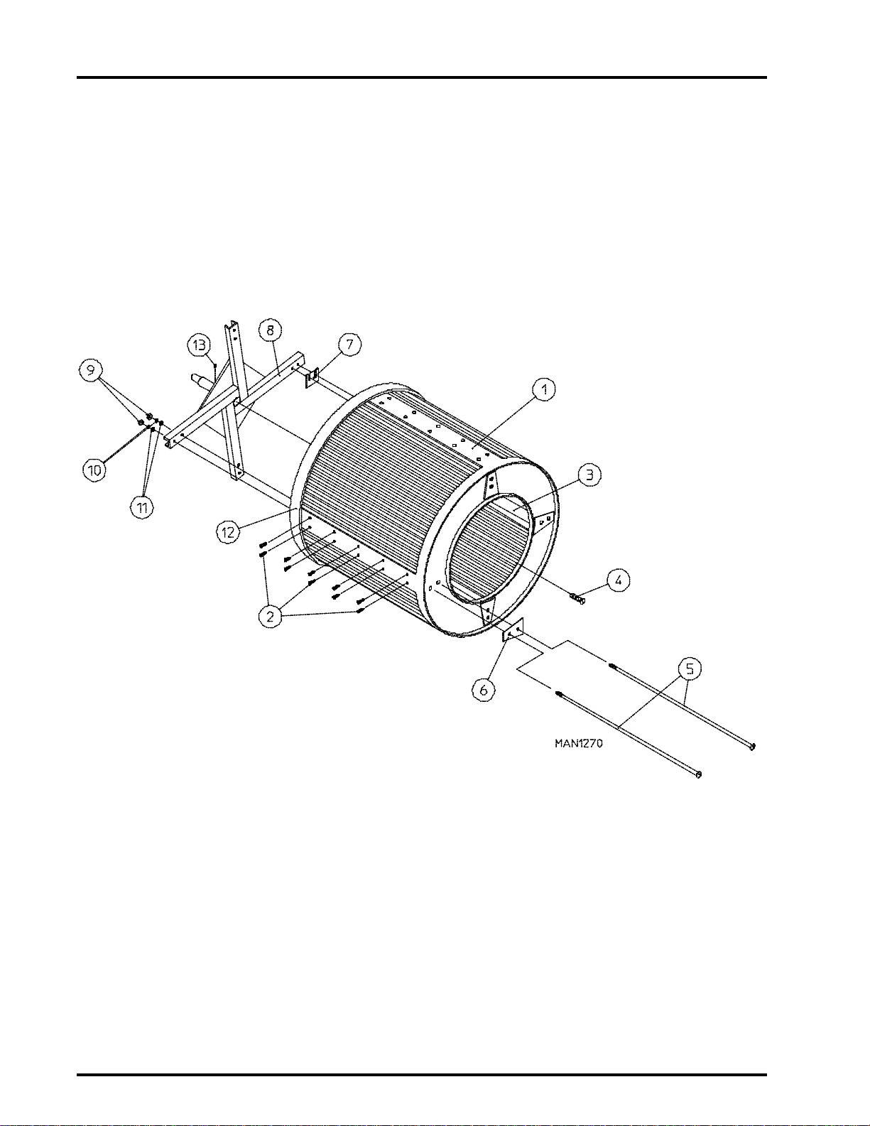
Tumbler (Basket)/Support Assemblies
Illus. No. Part No. Qty. Description
1 800707* 1 Tumbler (Basket) ONLY
800858* 1 Stainless Steel Tumbler (Basket) ONLY
800807 1 Tumbler (Basket) and Support Assembly Complete
(includes illus. nos. 1 through 12)
820054** 1 Tumbler (Basket) and Support Assembly Complete
(includes illus. nos. 1 through 12)
For Models with Rotation Sensor ONLY
800868 1 Stainless Steel Tumbler (Basket) and Support Assembly Complete
(includes illus. nos. 1 through 12)
820053** 1 Stainless Steel Tumbler (Basket) and Support Assembly Complete
(includes illus. nos. 1 through 12)
For Models with Rotation Sensor ONLY
2 150309 40 #10-16 x 1/2” Hex Head TEK Crimptite Screw
3 301300 4 Tumbler (Basket) Rib ONLY
301400 4 Stainless Steel Tumbler (Basket) Rib ONLY
4 150500 1 5/16-18 x 3/4” Socket Button Head Screw
5 100909 8 1/2-13 x 43” Tie Rod
6 301700 4 Tumbler (Basket) Reinforcing Plate ONLY
7 301701 *** Tumbler (Basket) Shim ONLY
8 800607 1 Tumbler (Basket) Support ONLY
880821 1 Tumbler (Basket) Support ONLY
(for models with rotation sensor Only)
9 152011 8 1/2-13 Hex Nut
10 153026 16 1/2” Lock Washer
11 153014 8 7/16” Flat Washer
12 116004 1 Felt Collar ONLY
-- 401010 1 #847 Adhesive for Felt Collar
13 821002 1 Rotation Magnet Holder Assembly
(for microprocessor models with optional rotation sensor)
21
* Felt collar is not included and must be ordered separately.
** Rotation Sensor Magnet Holder Assembly (Illus. no. 13) must be purchased separately.
*** As required.
Page 24
22
American Dryer Corporation
88 Currant Road / Fall River, MA 02720-4781
Tumbler Bearing Mount Assembly
Page 25

Telephone: (508) 678-9000
Fax: (508) 678-9447
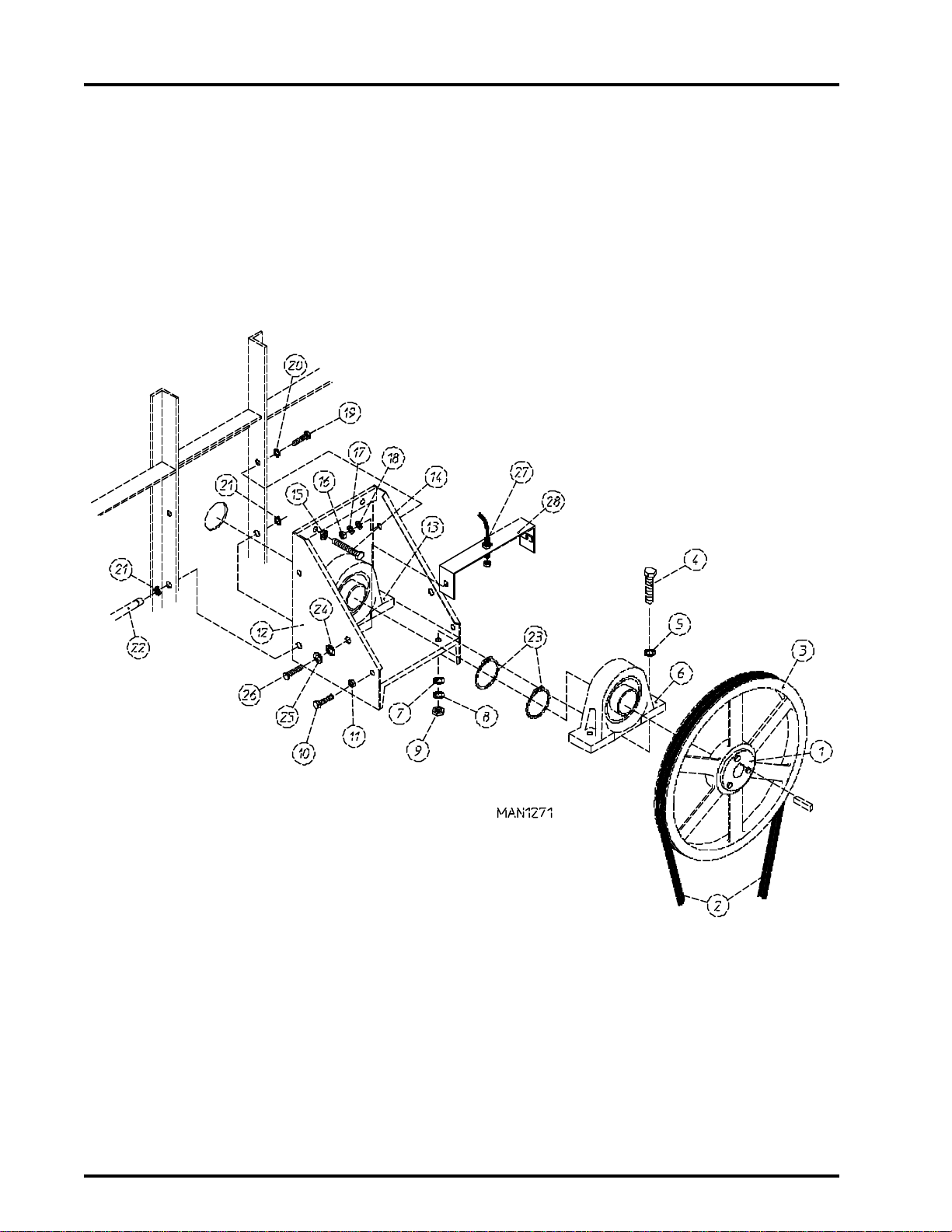
Tumbler Bearing Mount Assembly
Illus. No. Part No. Qty. Description
1 101108 1 2-1/4” SK Bushing
2* 100104 2 A68 “V” Belt
3 101111 1 18” Tumbler (Basket) Pulley
4 150602 4 5/8-11 x 3” Hex Head Machine Bolt
5 153016 4 5/8” Flat Washer
6 100204 1 2-1/4” Pillow Block Bearing ONLY
7 153016 4 5/8” Flat Washer
8 153015 4 5/8” Lock Washer
9 152010 4 5/8-11 Hex Nut
10 150600 2 3/8-16 x 1-1/2” Hex Head Machine Bolt
11 152005 2 3/8-16 Hex Nut
12 801102 1 Tumbler Bearing Mount Assembly
(includes illus. nos. 4 through 13)
13 100204 1 2-1/4” Pillow Block Bearing ONLY
14 150603 2 1/2-13 x 3” Square Head Machine Bolt
15 152011 2 1/2-13 Hex Nut
16 152005 2 3/8-16 Hex Nut
17 153005 2 3/8” Lock Washer
18 153004 4 3/8” Flat Washer
19 150600 2 3/8-16 x 1-1/2” Hex Head Machine Bolt
20 153004 2 3/8” Flat Washer
21 100801 2 5/8” Retaining Ring
22 301810 1 (5/8”) Hinge Pin
23 100811 2 2-1/4” Retaining Ring
24 153018 2 1/4” Flat Washer
25 153007 2 1/4” Split Lock Washer
26 150512 2 1/4-20 x 1/2” Hex Head Machine Bolt
27 824807 1 Rotational Sensor Assembly
28 880841 1 Rotational Sensor Mounting Bracket
23
* Replace in matched sets (both belts).
Page 26

24
American Dryer Corporation
88 Currant Road / Fall River, MA 02720-4781
Idler Bearing Mount Assembly
Page 27

Telephone: (508) 678-9000
Fax: (508) 678-9447
Idler Bearing Mount Assembly
Illus. No. Part No. Qty. Description
1 101110 1 1” Bushing
2 101113 1 2A3.0 Pulley
3* 100104 2 A68 “V” Belt
4 101107 1 1” SK Bushing
5* 100102 2 3V 740 “V” Belt
6 101112 1 19” Idler Pulley
7 100715 1 1/4” x 1/4” x 4-5/8” Key
8 301852 1 1” Idler Shaft ONLY
9 100205 1 1” Pillow Block Bearing
10 153004 4 3/8” Flat Washer
11 150600 4 3/8-16 x 1-1/2” Hex Head Machine Bolt
12 150510 6 1/4-20 x 1/2” Hex Head Machine Bolt
13 150509 2 5/16-18 x 3” Hex Head Machine Bolt
14 153001 6 5/16” Flat Washer
15 152004 6 5/16-18 Hex Nut
16 153002 4 5/16” Lock Washer
17 801001 1 Idler Bearing Mount Assembly Complete
(includes illus. nos. 7 through 11 and 17 through 25)
311401 1 Idler Bearing Mount ONLY
18 100205 1 1” Pillow Block Bearing
19 153004 4 3/8” Flat Washer
20 153005 4 3/8” Lock Washer
21 152005 4 3/8-16 Hex Nut
22 103005 1 Idler Adjustment Hinge ONLY
23 153007 6 1/4” Lock Washer
24 152002 6 1/4-20 Hex Nut
25
* Replace in matched sets (both belts).
Page 28

26
American Dryer Corporation
88 Currant Road / Fall River, MA 02720-4781
Totally Enclosed, Fan-Cooled (T.E.F.C.) Tumbler (Basket) Motor Mount Assembly
Page 29

Telephone: (508) 678-9000
Fax: (508) 678-9447
Totally Enclosed, Fan-Cooled (T.E.F.C.) Tumbler (Basket) Motor Mount Assembly
Illus. No. Part No. Qty. Description
1 101121 1 5/8” SK Bushing
2 101114 1 2.65” Pulley
(for 60 Hz models Only)
101120 1 3.15” Pulley
(for 50 Hz models Only)
3* 100102 2 3V 740 “V” Belt
4 120200 1 3/8” x 90° Connector
5 150501 4 5/16-18 x 3/4” Hex Head Machine Bolt
6 153001 4 5/16” Flat Washer
7 100029 1 3/4 HP 208/230/280/460v 3ø 50/60 Hz Totally Enclosed, Fan-Cooled
(T.E.F.C.) Motor (56Z frame)
8 800952 1 Tumbler (Basket) Motor Mount ONLY (56Z frame)
800953** 1 (60 Hz) Totally Enclosed, Fan-Cooled (T.E.F.C.) Tumbler (Basket)
Motor Mount Assembly Complete
(includes illus. nos. 1, 2, 5 through 11, 15, and 16)
For 60 Hz Models ONLY
800955** 1 (50 Hz) Totally Enclosed, Fan-Cooled (T.E.F.C.) Tumbler (Basket)
Motor Mount Assembly Complete
(includes illus. nos. 1, 2, 5 through 11, 15, and 16)
For 50 Hz Models ONLY
9 152004 4 5/16-18 Hex Nut
10 153002 4 5/16” Lock Washer
11 153001 4 5/16” Flat Washer
12 152004 4 5/16-18 Hex Nut
13 153002 4 5/16” Lock Washer
14 153001 4 5/16” Flat Washer
15 150619 1 3/18-16 x 3” Hex Head Machine Bolt
16 152005 2 3/8-16 Hex Nut
27
* Replace in matched sets (both belts).
** Specify voltage when ordering.
IMPORTANT: For voltages higher than 460 VAC - 50 Hz, contact the factory for correct part number of
motor or motor mount assembly.
Page 30

28
American Dryer Corporation
88 Currant Road / Fall River, MA 02720-4781
Blower Motor Mount Assembly
for Gas Models ONLY
Illus. No. Part No. Qty. Description
1* 100119 2 5L 320 “V” Belt
2 101138 1 SDS x 1-1/8” Bushing
3 101135 1 2B x 5.4 Pulley
4 100706 1 5/16” x 5/16” x 1-3/8” Key
5 100043 1 3 HP 208/230/460v 60 Hz and 380/416v 3ø 50 Hz ONLY Motor
100081 1 3 HP 220v 3ø 50 Hz Motor
6 332198 1 Motor Adjustment Plate
7 821012 1 Motor Bolt Plate Assembly
8 152005 4 3/8-16 Hex Nut
9 153005 4 3/8” Lock Washer
10 153004 4 3/8” Flat Washer
11 101194 1 SDS x 1-3/8” Bushing
(for 60 Hz models Only)
101152 1 SH x 1-3/8” Bushing
(for 50 Hz models Only)
Page 31

Telephone: (508) 678-9000
Fax: (508) 678-9447
Blower Motor Mount Assembly
for Gas Models ONLY
Illus. No. Part No. Qty. Description
12 101147 1 2B x 4.8 Pulley
(for 60 Hz models Only)
101148 1 2B x 4.0 Pulley
(for 50 Hz models Only)
13 100706 1 5/16” x 5/16” x 1-3/8” Key
14 317400 1 Impellor (fan) Shaft
15 100802 2 1-3/8” Retaining Ring
16 880879 2 1-3/8” Pillow Block Bearing with Set Screws and Grease Fitting
154326 4 5/16 x 3/8” Allen Set Screw ONLY
170511 2 1/8-27 N.P.T. Grease Fitting ONLY
17 153004 4 3/8” Flat Washer
18 153005 4 3/8” Lock Washer
19 150601 4 3/8-16 x 2” Hex Head Machine Bolt
20 850480 1 Blower Motor Mount ONLY
820350* 1 Motor Mount Assembly Complete
(includes illus. nos. 1 through 20 and 24 through 32)
(for 60 Hz models Only)
820252 1 Motor Mount Assembly Complete
(includes illus. nos. 1 through 20 and 24 through 32)
For 220v 50 Hz Models ONLY
820351* 1 Motor Mount Assembly Complete
(includes illus. nos. 1 through 20 and 24 through 32)
For 380/416v 50 Hz Models ONLY
21 152005 8 3/8-16 Hex Nut
22 153005 8 3/8” Lock Washer
23 153004 8 3/8” Flat Washer
24 150609 2 1/2-13 x 4-1/2” Hex Head Machine Bolt
25 152011 2 1/2-13 Hex Nut
26 117600 4 Noise Suppressor Tape (sold by the foot)
27 100603 1 16” Impellor with 3/4” Bore
28 100714 1 3/16” x 3/16” x 1-7/8” Key
29 153050 1 1/2” Flat Washer
30 152006 2 1/2-20 Left Hand Jam Nut
31 820379 1 Blower Motor Mount Belt Guard
32 150309 4 #10-16 x 1/2” Hex Head TEK Crimptite Screw
29
* Replace in matched sets (both belts).
** Specify voltage when ordering.
IMPORTANT: For voltages higher than 460 VAC - 50 Hz, contact the factory for correct part number of
motor or motor mount assembly.
Page 32

30
American Dryer Corporation
88 Currant Road / Fall River, MA 02720-4781
Blower Motor Mount Assembly
for Electric Models ONLY
Illus. No. Part No. Qty. Description
1* 100119 2 5L 320 “V” Belt (for 60 Hz models Only)
100118 2 5L 310 “V” Belt (for 50 Hz models Only)
2 101138 1 SDS x 1-1/8” Bushing
3 101147 1 2B x 5.4 Pulley (for 60 Kw electric oven models Only)
101135 1 2B x 5.4 Pulley (for 72 Kw electric oven models Only)
101185 1 2B x 6.2 Pulley (for 80 Kw electric oven models Only)
4 100706 1 5/16” x 5/16” x 1-3/8” Key
5 100043 1 3 HP 208/230/460v 60 Hz and 380/416v 3ø 50 Hz Motor
100081 1 3 HP 220v 3ø 50 Hz Motor
6 332198 1 Motor Adjustment Plate
7 821012 1 Motor Bolt Plate Assembly
8 152005 4 3/8-16 Hex Nut
9 153005 4 3/8” Lock Washer
10 153004 4 3/8” Flat Washer
11 101194 1 SDS x 1-3/8” Bushing (for 60 Hz models Only)
101152 1 SH x 1-3/8” Bushing (for 50 Hz models Only)
12 101147 1 2B x 4.8 Pulley (for 60 Hz models Only)
101148 1 2B x 4.0 Pulley (for 50 Hz models Only)
13 100706 1 5/16” x 5/16” x 1-3/8” Key
14 317400 1 Impellor (fan) Shaft
15 100802 2 1-3/8” Retaining Ring
16 880879 2 1-3/8” Pillow Block Bearing with Set Screws and Grease Fitting
154326 4 5/16 x 3/8” Allen Set Screw ONLY
170511 2 1/8-27 N.P.T. Grease Fitting ONLY
Page 33

Telephone: (508) 678-9000
Fax: (508) 678-9447
Blower Motor Mount Assembly
for Electric Models ONLY
Illus. No. Part No. Qty. Description
17 153004 4 3/8” Flat Washer
18 153005 4 3/8” Lock Washer
19 150601 4 3/8-16 x 2” Hex Head Machine Bolt
20 850480 1 Blower Motor Mount ONLY
820352** 1 60 Kw Motor Mount Assembly Complete
(includes illus. nos. 1 through 20 and 24 through 32)
For 60 Hz Models ONLY
820353** 1 60 Kw Motor Mount Assembly Complete
(includes illus. nos. 1 through 20 and 24 through 32)
For 380/416v 50 Hz Models ONLY
820251 1 60 Kw Motor Mount Assembly Complete
(includes illus. nos. 1 through 20 and 24 through 32)
For 220v 50 Hz Models ONLY
820350** 1 72 Kw Motor Mount Assembly Complete
(includes illus. nos. 1 through 20 and 24 through 32)
For 60 Hz Models ONLY
820351** 1 72 Kw Motor Mount Assembly Complete
(includes illus. nos. 1 through 20 and 24 through 32)
For 380/416v 50 Hz Models ONLY
820252 1 72 Kw Motor Mount Assembly Complete
(includes illus. nos. 1 through 20 and 24 through 32)
For 220v 50 Hz Models ONLY
800959** 1 80 Kw Motor Mount Assembly Complete
(includes illus. nos. 1 through 20 and 24 through 32)
For 60 Hz Models ONLY
800960** 1 80 Kw Motor Mount Assembly Complete
(includes illus. nos. 1 through 20 and 24 through 32)
For 380/416v 50 Hz Models ONLY
820254 1 80 Kw Motor Mount Assembly Complete
(includes illus. nos. 1 through 20 and 24 through 32)
For 220v 50 Hz Models ONLY
21 152005 8 3/8-16 Hex Nut
22 153005 8 3/8” Lock Washer
23 153004 8 3/8” Flat Washer
24 150609 2 1/2-13 x 4-1/2” Hex Head Machine Bolt
25 152011 2 1/2-13 Hex Nut
26 117600 4 Noise Suppressor Tape (sold by the foot)
27 100603 1 16” Impellor with 3/4” Bore
28 100714 1 3/16” x 3/16” x 1-7/8” Key
29 153050 1 1/2” Flat Washer
30 152006 2 1/2-20 Left Hand Jam Nut
31 820379 1 Blower Motor Mount Belt Guard
32 150309 4 #10-16 x 1/2” Hex Head TEK Crimptite Screw
31
* Replace in matched sets (both belts).
** Specify voltage when ordering.
IMPORTANT: For voltages higher than 460 VAC - 50 Hz, contact the factory for correct part number of
motor or motor mount assembly.
Page 34

32
American Dryer Corporation
88 Currant Road / Fall River, MA 02720-4781
Blower Motor Mount Assembly
for Steam Models ONLY
Illus. No. Part No. Qty. Description
1* 100145 2 BX-32 “V” Belt (for 60 Hz models Only)
100156 2 5L 320 “V” Belt (for 50 Hz models Only)
2 101138 1 SDS x 1-1/8” Bushing
3 101175 1 2B x 6.8 Pulley
4 100706 1 5/16” x 5/16” x 1-3/8” Key
5 100043 1 3 HP 208/230/460v 60 Hz and 380/416v 3ø 50 Hz Motor
100081 1 3 HP 220v 3ø 50 Hz Motor
6 332198 1 Motor Adjustment Plate
7 821012 1 Motor Bolt Plate Assembly
8 152005 4 3/8-16 Hex Nut
9 153005 4 3/8” Lock Washer
10 153004 4 3/8” Flat Washer
11 101194 1 SDS x 1-3/8” Bushing (for 60 Hz models Only)
101152 1 SH x 1-3/8” Bushing (for 50 Hz models Only)
12 101147 1 2B x 4.8 Pulley (for 60 Hz models Only)
101148 1 2B x 4.0 Pulley (for 50 Hz models Only)
Page 35

Telephone: (508) 678-9000
Fax: (508) 678-9447
Blower Motor Mount Assembly
for Steam Models ONLY
Illus. No. Part No. Qty. Description
13 100706 1 5/16” x 5/16” x 1-3/8” Key
14 317400 1 Impellor (fan) Shaft
15 100802 2 1-3/8” Retaining Ring
16 880879 2 1-3/8” Pillow Block Bearing with Set Screws and Grease Fitting
154326 4 5/16 x 3/8” Allen Set Screw ONLY
170511 2 1/8-27 N.P.T. Grease Fitting ONLY
17 153004 4 3/8” Flat Washer
18 153005 4 3/8” Lock Washer
19 150601 4 3/8-16 x 2” Hex Head Machine Bolt
20 850480 1 Blower Motor Mount ONLY
820383** 1 Motor Mount Assembly Complete
(includes illus. nos. 1 through 20 and 24 through 32)
For 60 Hz Models ONLY
820253 1 Motor Mount Assembly Complete
(includes illus. nos. 1 through 20 and 24 through 32)
For 220v 50 Hz Models ONLY
820384** 1 Motor Mount Assembly Complete
(includes illus. nos. 1 through 20 and 24 through 32)
For 380/416v 50 Hz Models ONLY
21 152005 8 3/8-16 Hex Nut
22 153005 8 3/8” Lock Washer
23 153004 8 3/8” Flat Washer
24 150609 2 1/2-13 x 4-1/2” Hex Head Machine Bolt
25 152011 2 1/2-13 Hex Nut
26 117600 4 Noise Suppressor Tape (sold by the foot)
27 100603 1 16” Impellor with 3/4” Bore
28 100714 1 3/16” x 3/16” x 1-7/8” Key
29 153050 1 1/2” Flat Washer
30 152006 2 1/2-20 Left Hand Jam Nut
31 820379 1 Blower Motor Mount Belt Guard
32 150309 4 #10-16 x 1/2” Hex Head TEK Crimptite Screw
33
* Replace in matched sets (both belts).
** Specify voltage when ordering.
IMPORTANT: For voltages higher than 460 VAC - 50 Hz, contact the factory for correct part number of
motor or motor mount assembly.
Page 36

34
American Dryer Corporation
88 Currant Road / Fall River, MA 02720-4781
Direct Spark Ignition (DSI) Burner Assembly
for Gas Models ONLY
Illus. No. Part No. Qty. Description
1 880874* 1 Direct Spark Ignition (DSI) Natural Gas Burner Assembly
Complete Less Orifices
(includes illus. nos. 1 through 16, 18 through 36, and 39)
880875* 1 Direct Spark Ignition (DSI) Liquid Propane (L.P.) Burner Assembly
Complete Less Orifices
(includes illus. nos. 1 through 16 and 18 through 39)
820201 1 Burner Box ONLY
2 331291 1 Pipe Bracket
(for models mfd. as of February 1, 1995)
318364 1 Pipe Bracket
(for models mfd. prior to February 1, 1995)
3 150309 2 #10-16 x 1/2” Hex Head TEK Crimptite Screw
4 142813 1 3/4” x 33-1/2” Nipple
(for models mfd. as of February 1, 1995)
142821 1 3/4” x 36” Nipple
(for models mfd. prior to February 1, 1995)
5 141300 1 3/4” Union Shutoff
6 142701 1 3/4” Close Nipple
7 142601 1 3/4” Union
8 142710 1 3/4” x 4” Nipple
(for models mfd. as of February 1, 1995)
142701 1 3/4” Close Nipple
(for models mfd. prior to February 1, 1995)
9 142504 1 3/4” x 90° Elbow
10 142710 1 3/4” x 4” Nipple
(for models mfd. as of February 1, 1995)
142734 1 3/4” x 5-1/2” Nipple
(for models mfd. as of February 1, 1995)
Page 37

Telephone: (508) 678-9000
Fax: (508) 678-9447
Direct Spark Ignition (DSI) Burner Assembly
for Gas Models ONLY
Illus. No. Part No. Qty. Description
11 150309 2 #10-16 x 1/2” Hex Head TEK Crimptite Screw
12 354030 1 Flat Gas Pipe Bracket
13 140026 1 Direct Spark Ignition (DSI) 3/4” 24 VAC Redundant
(natural gas) Gas Valve
140411 1 24 VAC Gas Valve Liquid Propane (L.P.) Conversion Kit
14 150309 2 #10-16 x 1/2” Hex Head TEK Crimptite Screw
15 331291 1 Gas Valve Pipe Bracket
16 141208 1 3-Port Manifold
17** 140837 3 #8 Burner Orifice (natural gas) ONLY
140818 3 #31 Burner Orifice (liquid propane [L.P.] gas) ONLY
18 150309 4 #10-16 x 1/2” Hex Head TEK Crimptite Screw
19 331288 1 Manifold Support ONLY
20 150309 6 #10-16 x 1/2” Hex Head TEK Crimptite Screw
21 141110 3 Burner Tube ONLY
22 150309 2 #10-16 x 1/2” Hex Head TEK Crimptite Screw
23 331287 1 Burner Tube Support ONLY
24 150309 2 #10-16 x 1/2” Hex Head TEK Crimptite Screw
25 150309 6 #10-16 x 1/2” Hex Head TEK Crimptite Screw
26 --------- 1 Sail Switch
(refer to Sail Switch Assembly on page 37)
27 331289 1 Burner Box Cover Plate ONLY
28 150309 1 #10-16 x 1/2” Hex Head TEK Crimptite Screw
29 331290 1 Ignitor/Flame-Probe Sight Hole Disc ONLY
30 880325 1 Ignitor/Flame-Probe Assembly Kit
(includes high voltage [HV] wire and connector)
305410 1 Direct Spark Ignition (DSI) Ignitor Gap Feeler Gauge ... Not Illustrated
31 880330 1 Direct Spark Ignition (DSI) Ignitor High Volage (HV)
Wire/Connector ONLY
32 150309 2 #10-16 x 1/2” Hex Head TEK Crimptite Screw
33 151000 2 #6-32 Pal Nut
34 130401 1 330° Hi-Limit ONLY
35 150001 2 #6-32 x 1/2” Round Head Machine Screw
36 142924 1 1” to 3/4” Reducing Coupling
37 332256 1 Liquid Propane (L.P.) Burner Baffle
(for liquid propane [L.P.] models Only)
38 150309 5 #10-16 x 1/2” Hex Head TEK Crimptite Screw
--- 880876** 1 AD-115 Direct Spark Ignition (DSI) Liquid Propane (L.P.) Conversion Kit
39 142907 1 3/4” to 1/2” Reducing Bushing
35
* Orifices are not included and must be ordered separately.
** Consult factory for elevations over 2,000 feet.
Page 38

36
American Dryer Corporation
88 Currant Road / Fall River, MA 02720-4781
Direct Spark Ignition (DSI) Module Mount Assembly
for Gas Models ONLY
Illus. No. Part No. Qty. Description
1 880815 1 ADC Direct Spark Ignition (DSI) Module ONLY - 50/60 Hz
2 820100 1 Direct Spark Ignition (DSI) Module Mount Assembly ONLY
3 121400 3 Universal Bushing
4 152014 3 1/4-20 Free Spin Wash Nut
5 150301 1 #8-18 x 7/16” Phillips Pan Head TEK Screw
6 153010 4 #6 Star Washer
7 152000 4 #6-32 Hex Nut
Page 39

Telephone: (508) 678-9000
Fax: (508) 678-9447
Sail Switch Assembly
37
Illus. No. Part No. Qty. Description
1 105500 1 Sail Switch Actuator Rod
2 319202 1 Sail Switch Damper (flat)
3 154002 1 1/8” Push-on Fastener
4 802800 1 Sail Switch Box with Cover and Bracket ONLY
5 150300 2 #10 x 1/2” Hex Washer TEK Screw
6 150303 2 #4 x 3/4” Pan Head “A” Machine Screw
7 122200 1 Sail Switch ONLY
8 802799 1 Sail Switch Box Cover and Bracket ONLY
9 150309 2 #10-16 x 1/2” Hex Head TEK Crimptite Screw
10 154004 1 Twin Speed Nut
802801 1 Sail Switch Box Assembly Complete
(includes illus. nos. 1 through 4 and 6 through 10)
Page 40

38
American Dryer Corporation
88 Currant Road / Fall River, MA 02720-4781
Electric Oven Assembly
Page 41

Telephone: (508) 678-9000
Fax: (508) 678-9447
Electric Oven Assembly
Illus. No. Part No. Qty. Description
1 803015 1 Electric Oven Box ONLY
---------* 1 Electric Oven Assembly Complete
2 ---------* 18 Electric Element
3 802802 1 Safety Control Bracket ONLY
4 150301 2 #8-18 x 7/16” Phillips Pan Head TEK Screw
5 130400 1 290° Hi-Limit ONLY
6 150309 4 #10-16 x 1/2” Hex Head TEK Crimptite Screw
7 802800 1 Sail Switch Box with Cover and Bracket ONLY
802801 1 Sail Switch Box Assembly Complete
(includes illus. nos. 7 through 15)
8 154004 1 Twin Speed Nut
9 150309 2 #10-16 x 1/2” Hex Head TEK Crimptite Screw
10 802799 1 Sail Switch Box Cover and Bracket ONLY
11 122200 1 Sail Switch ONLY
12 150303 2 #4 x 3/4” Pan Head “A” Machine Screw
13 105500 1 Sail Switch Actuator Rod
14 319202 1 Sail Switch Damper (flat)
15 154002 1 1/8” Push-On Fastener
16 150309 8 #10-16 x 1/2” Hex Head TEK Crimptite Screw
17 803101 4 Element Cover ONLY
18 120081 36 Internal Ceramic Insulator
19 120080 36 External Ceramic Insulator
20 152008 36 #10-32 Hex Nut
21 121011* -- Bus Bar (sold by the foot)
22 121010* -- L-70 Ground Lug
23 153009 36 #10 Star Washer
24 152008 36 #10-32 Hex Nut
25 150309 14 #10-16 x 1/2” Hex Head TEK Crimptite Screw
26 320822 1 Cover ONLY
27 --------* -- Oven Wire (sold by the foot)
39
* Refer to 60 Kw Electric Oven Component Application Charts on page 52.
Refer to 72 Kw and 80 Kw Electric Oven Component Application Charts on page 53.
Page 42

40
American Dryer Corporation
88 Currant Road / Fall River, MA 02720-4781
Electric Oven Relay Box Assembly
208/240 VAC 3ø 50/60 Hz
Illus. No. Part No. Qty. Description
1 320902 1 Electric Oven Relay Box Cover
2 150301 12 #8-18 x 7/16” Phillips Pan Head TEK Screw
3 322808 1 Control Box Cover Plate ONLY
4 150108 2 #8-32 x 1/2” Phillips Pan Head Machine Screw
5 120710 1 Power Distribution Block
6 151001 2 #8-32 Pal Nut
7 121400 2 Universal Bushing
8 132004 1 Transformer
(for ALL microprocessor controller [computer] models
and timer models)
9 150108 1 #8-32 x 1/2” Phillips Pan Head Machine Screw
10 121010 1 L-70 Ground Lug
11 151001 1 #8-32 Pal Nut
12 150108 3 #8-32 x 1/2” Phillips Pan Head Machine Screw
13 131385 2 TPST 112-Amp, 24 VAC Relay
14 151001 3 #8-32 Pal Nut
15 150521 4 1/4-20 x 2” Carriage Bolt
16 120706 2 Power Distribution Block
17 152014 4 1/4-20 Free Spin Wash Nut
Page 43

Telephone: (508) 678-9000
Fax: (508) 678-9447
Electric Oven Relay Box Assembly
380/416/480 VAC 3ø 50/60 Hz
41
Illus. No. Part No. Qty. Description
1 320902 1 Electric Oven Relay Box Cover
2 150301 12 #8-18 x 7/16” Phillips Pan Head TEK Screw
3 322808 1 Control Box Cover Plate ONLY
4 150300 3 #10 x 1/2” Hex Washer TEK Screw
5 132004 1 Transformer
6 121400 2 Universal Bushing
7 150108 3 #8-32 x 1/2” Phillips Pan Head Machine Screw
8 121010 1 L-70 Ground Lug
9 151001 1 #8-32 Pal Nut
10 151001 3 #8-32 Pal Nut
11 152014 2 1/4-20 Free Spin Wash Nut
12 150108 1 #8-32 x 1/2” Phillips Pan Head Machine Screw
13 131385 1 TSPT 112-Amp, 24 VAC Relay
14 120706 1 Power Distribution Block
15 150521 2 1/4-20 x 2” Carriage Bolt
(for ALL electric models - 380 VAC through 480 VAC)
Page 44

42
American Dryer Corporation
88 Currant Road / Fall River, MA 02720-4781
Steam Damper Assembly
Page 45

Telephone: (508) 678-9000
Fax: (508) 678-9447
Steam Damper Assembly
Illus. No. Part No. Qty. Description
1 165012 1 Steam Coil Assembly
165019 1 Steel Steam Coil Assembly
2 153002 6 5/16” Lock Washer
3 152004 6 5/16-18 Hex Nut
4 152002 4 1/4-20 Hex Nut
5 153007 4 1/4” Lock Washer
6 820321 2 Steam Damper Hinge Assembly
7 820320 1 Steam Damper Assembly
(includes illus. nos. 7, 10, and 11)
8 153007 4 1/4” Lock Washer
9 152002 4 1/4-20 Hex Nut
10 115995 84 Steam Damper Gasket (sold by the inch)
11 102350 1 Steam Damper Foam (68-1/2” length)
12 151007 1 7/16-20 Stainless Steel Acorn Nut
13 100499 1 1-1/2” Bore x 3” Stroke Piston
14 100500 1 Piston Support Bracket
15 152002 4 1/4-20 Hex Nut
16 153007 4 1/4” Lock Washer
17 100472 1 1/4” x 1/8” Connector
18 143110 1 1/4” Tubing (sold by the foot)
19 100472 1 1/4” x 1/8” Connector
20 100496 1 1/8” Needle Valve
21 143238 1 1/8” Close Nipple
22 100498 1 3-Way Micro Valve - 24 VAC
23 150002 2 #6-32 x 1” Phillips Round Head Machine Screw
24 153010 2 #6 Star Washer
25 152000 2 #6-32 Hex Nut
26 330987 1 Micro Valve Support Bracket
27 152002 2 1/4-20 Hex Nut
28 153007 2 1/4” Lock Washer
29 100520 1 1/8” N.P.T. Silencer (muffler)
43
Page 46

44
American Dryer Corporation
88 Currant Road / Fall River, MA 02720-4781
Microprocessor Reversing Control Box Assembly
for Gas, Steam, and Electric Models mfd. prior to March 29, 1995
Illus. No. Part No. Qty. Description
1 150301 6 #8-18 x 7/16” Phillips Pan Head TEK Screw
2 322815 1 Control Box Cover Plate ONLY (8-1/2” x 15-1/2”)
3 137060 1 Arc Suppressor (A.S.) Board (3)
4 137013 4 Nylon Standoff
5 153002 2 5/16” Lock Washer
6 152004 2 5/16-18 Hex Nut
7 150108 4 #8-32 x 1/2” Phillips Pan Head Machine Screw
8 132445 1 3 HP Impellor (fan/blower) Contactor
9 151001 2 #8-32 Pal Nut
10 322816 1 Contactor Mounting Panel ONLY (7” x 15-1/2”)
11 150108 4 #8-32 x 1/2” Phillips Pan Head Machine Screw
12 132431 1 Reversing (Impellor/Blower/Fan) Contactor - 24 VAC
132432 1 Contactor Replacement Coil - 24 VAC
13 151001 4 #8-32 Pal Nut
14 120704 1 3-Position Power Distribution Block
15 150108 2 #8-32 x 1/2” Phillips Pan Head Machine Screw
16 151001 4 #8-32 Pal Nut
17 --------- -- Transformer
(refer to Step Down Transformer Usage Listing on page 50)
18 150300 2 #10 x 1/2” Hex Washer TEK Screw
Page 47

Telephone: (508) 678-9000
Fax: (508) 678-9447
Microprocessor Reversing Contactor Mounting Panel Assembly
for Electric Models mfd. as of March 29, 1995
45
Illus. No. Part No. Qty. Description
1 132445 1 3 HP Contactor
2 132448 1 Reversing Contactor
3 150522 1 1/4 x 20 x 1/2 Self Tapping Hex Head
4 121010 1 L-70 Ground Lug
5 150008 2 #6-32 x 1-1/4” Phillips Round Head Machine Screw
6 120701 1 4-Position Terminal Block
7 120765 2 End Stop
8 137013 4 Nylon Standoff
9 150309 3 #10-16 x 1/2” Hex Head TEK Crimptite Screw
10 137060 1 Arc Suppressor (A.S.) Board
11 120768 1 8-1/2” Din Mounting Rail
12 151000 2 #6-32 Pal Nut
13 322816 1 Large Reversing Relay Mounting Panel
14 152004 2 5/16-18 Hex Nut
15 153002 2 5/16” Split Lock Washer
16 132468 1 4-6 Amp Blower Motor Overload
17 150108 2 #8-32 x 1/2” Phillips Pan Head Machine Screw
18 -------- 1 Step Down Transformer for Gas and Steam Models
(refer to Step Down Transformer Usage Listing on page 50)
Step Down Transformer for Electric Models
(refer to Electric Oven Relay Box Assembly on page 40 and page 41)
19 151001 2 #8-32 Pal Nut
Page 48

46
American Dryer Corporation
88 Currant Road / Fall River, MA 02720-4781
Dual Timer Reversing Control Box Assembly
for Gas, Steam, and Electric Models mfd. prior to March 29, 1995
Illus. No. Part No. Qty. Description
1 150301 6 #8-18 x 7/16” Phillips Pan Head TEK Screw
2 322815 1 Control Box Cover Plate ONLY (8-1/2” x 15-1/2”)
3 132198 1 Reversing Timer ONLY (50/60 Hz) - 24 VAC
4 150108 2 #8-32 x 1/2” Phillips Pan Head Machine Screw
5 151001 2 #8-32 Pal Nut
6 153002 2 5/16” Lock Washer
7 152004 2 5/16-18 Hex Nut
8 150108 4 #8-32 x 1/2” Phillips Pan Head Machine Screw
9 132445 1 3 HP Impellor (Blower/Fan) Contactor
10 151001 4 #8-32 Pal Nut
11 322816 1 Contactor Mounting Panel ONLY (7” x 15-1/2”)
12 150108 4 #8-32 x 1/2” Phillips Pan Head Machine Screw
13 132431 1 Reversing (Impellor/Blower/Fan) Contactor - 24 VAC
132432 1 Contactor Replacement Coil - 24 VAC
14 151001 4 #8-32 Pal Nut
15 120704 1 3-Position Power Distribution Block
16 150108 2 #8-32 x 1/2” Phillips Pan Head Machine Screw
17 151001 2 #8-32 Pal Nut
18 --------- -- Transformer
(refer to Step Down Transformer Usage Listing on page 50)
19 150300 2 #10 x 1/2” Hex Washer TEK Screw
Page 49

Telephone: (508) 678-9000
Fax: (508) 678-9447
Dual Timer Reversing Relay Mounting Panel Assembly
for Gas, Steam, and Electric Models mfd. as of March 29, 1995
47
Illus. No. Part No. Qty. Description
1 132445 1 3 HP Contactor
2 132448 1 Reversing Contactor
3 150522 1 1/4 x 20 x 1/2 Self Tapping Hex Head
4 121010 1 L-70 Ground Lug
5 150008 2 #6-32 x 1-1/4” Phillips Round Head Machine Screw
6 120701 1 4-Position Terminal Block
7 120765 2 End Stop
8 132198 1 Reversing Timer
9 150309 5 #10-16 x 1/2” Hex Head TEK Crimptite Screw
10 120768 1 8-1/2” Din Mounting Rail
11 151000 2 #6-32 Pal Nut
12 322816 1 Large Reversing Relay Mounting Panel
13 152004 2 5/16-18 Hex Nut
14 153002 2 5/16” Split Lock Washer
15 132468 1 4-6 Amp Blower Motor Overload
16 150108 2 #8-32 x 1/2” Phillips Pan Head Machine Screw
17 -------- 1 Step Down Transformer for Gas and Steam Models
(refer to Step Down Transformer Usage Listing on page 50)
Step Down Transformer for Electric Models
(refer to Electric Oven Relay Box Assembly on page 40 and page 41)
18 151001 2 #8-32 Pal Nut
Page 50

48
American Dryer Corporation
88 Currant Road / Fall River, MA 02720-4781
Extended Back Guard Assembly
for ALL 60 Hz Models mfd. as of January 26, 1995
for ALL 50 Hz Models mfd. as of January 9, 1995
Illus. No. Part No. Qty. Description
1 801510 1 Extended Back Guard Assembly
2 152005 4 3/8-16 Hex Nut
3 153005 4 3/8” Lock Washer
4 153004 4 3/8” Flat Washer
5 322815 1 Control Box Cover Plate ONLY (8-1/2” x 15-1/2”)
6 880185 1 12” to 14” Increaser for 60 kw, 72 kw, and Gas Models
850184 1 12” to 16” Increaser for 80 kw and Steam Models
Page 51

Telephone: (508) 678-9000
Fax: (508) 678-9447
Extended Back Guard Assembly
for ALL 60 Hz Models mfd. prior to January 26, 1995
for ALL 50 Hz Models mfd. prior to January 9, 1995
49
Illus. No. Part No. Qty. Description
1 801509 1 Back Guard Assembly
2 162005 4 3/8-16 Hex Nut
3 153005 4 3/8” Lock Washer
4 153004 4 3/8” Flat Washer
5 322815 1 Control Box Cover Plate ONLY (8-1/2” x 15-1/2”)
(for models mfd. as of January 4, 1993)
322808 1 Control Box Cover Plate ONLY (8-1/2” x 12”)
(for models mfd. prior to January 4, 1993)
Page 52

50
American Dryer Corporation
88 Currant Road / Fall River, MA 02720-4781
Step Down Transformer Usage Listing
STEP DOWN TRANSFORMER USAGE LISTING
(R EVERSING RELA Y BOX)
Heat Voltage
Gas
Steam
N/A = Not available.
N/R = Not required.
Wire
Service
380 3 or 4 132059 132059
416 3 or 4 132062 132062
400 3 or 4 132056 132056
460/480 3 or 4 132053 132053
575 3 132050 132050
Microprocessor Models Timer Models
Transformer Part Number
Page 53

Telephone: (508) 678-9000
Fax: (508) 678-9447
Direct Spark Ignition (DSI) Burner Assembly Specifications
ADG-115D
DI RECT SPARK IGNITION (DSI )
BURNER ORIFICE SPECIFICA TION*
Liquid Propane
Natural Gas
Qty.
D.M.S. Part No. D.M.S. Part No.
3 #8 140837 #31 140818
* Consult factory for elevations over 2,000 feet.
ADG-115D
DIRECT SPARK IGNITION (DSI)
(L.P.) Gas
51
BURNER ASSEMBLY SPECIFICATION
BTU/H Rating Natural Gas
343,000
NOTES: 1. Burner assemblies DO NOT include burner orifices.
They must be ordered separately.
2. When ordering burner assembly, specify model number
and serial number of the dryer.
880874 880875
Liquid Propane
(L.P.) Gas
ADG-115D
DIRECT SPARK IGNITION (DSI)
LIQUID PROPANE (L.P.)
KIT SPECIFICATION*
Kit Part No.
880876
* Consult factory for elevations over 2,000 feet.
Page 54

52
American Dryer Corporation
88 Currant Road / Fall River, MA 02720-4781
60 Kw Electric Oven Component Application Charts
For ALL dryers with 60 Kw Electric Oven Models mfd. as of April 11, 1995
Volts 208 230 380 416 480
Phase 3Ø 3Ø 3Ø 3Ø 3Ø
Wire 3 3 3 or 4 3 or 4 3 or 4
Oven Assy Part No. 815800 815802 815809 815805 815806
Qty. 18 18 18 18 18
Elements
Oven
Wire
Terminal
Lug
Bus Bar Part No. 121011
Size 3.3 Kw 3.3 Kw 3.3 Kw 3.3 Kw 3.3 Kw
Part No. 120070 120071 120069 120070 120071
Qty. 51’ 9’ 51’ 9’ 22’ 8’ 22’ 8’ 22’ 8’
Size #8 #10 #8 #10 #8 #10 #8 #10 #8 #10
Part No. 133100 133000 133100 133000 133100 133000 133100 133000 133100 133000
Qty. 18 18 9 9 9
Part No. 121010 121010 121010 121010 121010
2’ 2’ 3’ 3’ 3’
For ALL dryers with 60 Kw Electric Oven Models mfd. prior to April 11, 1995
Volts 208 230 380 416 480
Phase 3Ø 3Ø 3Ø 3Ø 3Ø
Wire 3 3 3 or 4 3 or 4 3 or 4
Oven Assy Part No. 815800 815802 815809 815805 815806
Qty. 12 6 12 6 12 6 12 6 12 6
Elements
Oven
Wire
60 Kw Oven 60 Kw Oven
Terminal
Lug
Bus Bar Part No. 121011 2’ 2’ 3’ 3’ 3’
Size 3 Kw 4 Kw 3 Kw 4 Kw 3 Kw 4 Kw 3 Kw 4 Kw 3 Kw 4 Kw
Part No. 120006 120008 120007 120009 120006 120008 120006 120008 120007 120009
Qty. 51’ 9’ 51’ 9’ 22’ 8’ 22’ 8’ 22’ 8’
Size #8 #10 #8 #10 #8 #10 #8 #10 #8 #10
Part No. 133100 133000 133100 133000 133100 133000 133100 133000 133100 133000
Qty. 18 18 9 9 9
Part No. 121010 121010 121010 121010 121010
NOTE: Oven wire and bus bar are sold by the foot.
Page 55

Telephone: (508) 678-9000
Fax: (508) 678-9447
72 Kw and 80 Kw Electric Oven Component Application Charts
Volts 208 230 380 416 480 600
Phase 3Ø 3Ø 3Ø 3Ø 3Ø 32
Wire 3 3 3 or 4 3 or 4 3 or 4 3 or 4
Oven Assy Part No. 815816 815817 815820 815821 815822 815828
Qty. 18 18 18 18 18 18
Elements
Oven
Wire
72 Kw Oven
Terminal
Lug
Bus Bar Part No. 121011 2’ 2’ 3’ 3’ 3’ 2’
Size 4 Kw 4 Kw 4 Kw 4 Kw 4 Kw 4 Kw
Part No. 120008 120009 120044 120008 120009 120028
Qty. 6’ 25’ 6’ 25’ 3’ 8’ 3’ 25’ 3’ 25’ 6’ 25’
Size 2 8 2 8 2 8 2 8 2 8 8 10
Part No. 133302 133100 133302 133100 133302 133100 133002 133100 133302 133100 133100 133000
Qty. 13 6 13 6 9 1 9 1 9 1 13 6
Part No. 121010 121012 121010 121012 121010 121012 121010 121012 121010 121012 121010 121012
53
Volts 208 230 380 416 480
Phase 3Ø 3Ø 3Ø 3Ø 3Ø
Wire 3 3 3 or 4 3 or 4 3 or 4
Oven Assy Part No. 815823 815824 815810 815826 815827
Qty. 18 18 18 18 18
Elements
Oven
Wire
Size 4.5 Kw 4.5 Kw 4.5 Kw 4.5 Kw 4.5 Kw
Part No. 120047 120048 120022 120047 120048
Qty. 6’ 25’ 6’ 25’ 3’ 25’ 3’ 25’ 3’ 25’
Size 2 8 2 8 1 8 1 8 2 8
Part No. 133302 133100 133302 133100 133301 133100 133301 133100 133302 133100
80 Kw Oven
Terminal
Lug
Bus Bar Part No. 121011 8’ 8’ 11’ 11’ 11’
NOTE: Oven wire and bus bar are sold by the foot.
Qty. 18 18 10 1 18 1 18 1
Part No. 121010 121010 121010 121012 121010 121012 121010 121012
Page 56

54
American Dryer Corporation
88 Currant Road / Fall River, MA 02720-4781
Electric Oven Power Distribution
for 60 Kw 208/240 VAC Microprocessor Models mfd. as of April 11, 1995
MICROPROCESSOR
60 KW ELECTRIC OVEN POWER DISTRIBUTION
(208/240V 3Ø 50/60 HZ)
Electric
Service
208v 3Ø 3, 4w 18 120070 165 8 8 10 131375 132004
240v 3Ø 3, 4w 18 120071 143 8 8 10 131375 132004
Qty.
Elements
Element
Number
Part
Oven
Amps
Wire Service
A B C
Contactor
24 VAC
Step Down
Transformer
Page 57

Telephone: (508) 678-9000
Fax: (508) 678-9447
Electric Oven Power Distribution
for 60 Kw 380/416/480 VAC Microprocessor Models mfd. as of April 11, 1995
MICROPROCESSOR
60 KW ELECTRIC OVEN POWER DISTRIBUTION
(380/416/480V 3Ø 50/60 HZ)
55
Electric
Service
380v 3Ø 3, 4w 18 120069 92 8 8 10 131385 132004
416v 3Ø 3, 4w 18 120070 84 8 8 10 131385 132004
480v 3Ø 3, 4w 18 120071 73 8 8 10 131385 132004
Qty.
Elements
Element
Part
Number
Oven
Amps
Wire Service
A B C
Contactor
24 VAC
Step Down
Transformer
Page 58

56
American Dryer Corporation
88 Currant Road / Fall River, MA 02720-4781
Electric Oven Power Distribution
for 60 Kw 208/240 VAC Dual Timer Models mfd. as of April 11, 1995
DUAL TIMER
60 KW ELECTRIC OVEN POWER DISTRIBUTION
(208/240V 3Ø 50/60 HZ)
Electric
Service
208v 3Ø 3, 4w 18 120070 165 8 8 10 131375 132004
240v 3Ø 3, 4w 18 120071 143 8 8 10 131375 132004
Qty.
Elements
Element
Number
Part
Oven
Amps
Wire Service
A B C
Contactor
24 VAC
Step Down
Transformer
Page 59

Telephone: (508) 678-9000
Fax: (508) 678-9447
Electric Oven Power Distribution
for 60 Kw 380/416/480 VAC Dual Timer Models mfd. as of April 11, 1995
DUAL TIMER
60 KW ELECTRIC OVEN POWER DISTRIBUTION
(380/416/480V 3Ø 50/60 HZ)
57
Electric
Service
380v 3Ø 3, 4w 18 120069 92 8 8 10 131385 132004
416v 3Ø 3, 4w 18 120070 84 8 8 10 131385 132004
480v 3Ø 3, 4w 18 120071 73 8 8 10 131385 132004
Qty.
Elements
Element
Part
Number
Oven
Amps
Wire Service
A B C
Contactor
24 VAC
Step Down
Transformer
Page 60

58
American Dryer Corporation
88 Currant Road / Fall River, MA 02720-4781
Electric Oven Power Distribution
for 60 Kw 208/240 VAC Models mfd. prior to April 11, 1995
60 KW ELECTRIC OVEN POWER DISTRIBUTION
(208/240V 3Ø 50/60 HZ)
Page 61

Telephone: (508) 678-9000
Fax: (508) 678-9447
Electric Oven Power Distribution
for 60 Kw 380/416/480 VAC Models mfd. prior to April 11, 1995
60 KW ELECTRIC OVEN POWER DISTRIBUTION
(380/416/480V 3Ø 50/60 HZ)
59
Page 62

60
American Dryer Corporation
88 Currant Road / Fall River, MA 02720-4781
Electric Oven Power Distribution
for 72 Kw 208/240 VAC Microprocessor Models mfd. as of April 11, 1995
MICROPROCESSOR
72 KW ELECTRIC OVEN POWER DISTRIBUTION
(208/240V 3Ø 50/60 HZ)
Electric
Service
208v 3Ø 3, 4w 18 120008 200 2 2 8 131385 132004
240v 3Ø 3, 4w 18 120009 174 2 2 8 131385 132004
Qty.
Elements
Element
Number
Part
Oven
Amps
Wire Service
A B C
Contactor
24 VAC
Step Down
Transformer
Page 63

Telephone: (508) 678-9000
Fax: (508) 678-9447
Electric Oven Power Distribution
for 72 Kw 600 VAC Microprocessor Models mfd. as of April 11, 1995
MICROPROCESSOR
72 KW ELECTRIC OVEN POWER DISTRIBUTION
(600V 3Ø 50/60 HZ)
61
Electric
Service
600v 3Ø 3, 4w 18 120028 69 8 8 18 131350 132097
Qty.
Elements
Element
Part
Number
Oven
Amps
Wire Service
A B C
Contactor
24 VAC
Step Down
Transformer
Page 64

62
American Dryer Corporation
88 Currant Road / Fall River, MA 02720-4781
Electric Oven Power Distribution
for 72 Kw 380/416/480 VAC Microprocessor Models mfd. as of April 11, 1995
MICROPROCESSOR
72 KW ELECTRIC OVEN POWER DISTRIBUTION
(380/416/480V 3Ø 50/60 HZ)
Electric
Service
380v 3Ø 3, 4w 18 120044 110 2 8 131385 132004
416v 3Ø 3, 4w 18 120008 100 2 8 131385 132004
480v 3Ø 3, 4w 18 120009 87 2 8 131385 132004
Qty.
Elements
Element
Part
Number
Oven
Amps
Wire
Service
A B
Contactor
24 VAC
Step Down
Transformer
Page 65

Telephone: (508) 678-9000
Fax: (508) 678-9447
Electric Oven Power Distribution
for 72 Kw 208/240 VAC Dual Timer Models mfd. as of April 11, 1995
DUAL TIMER
72 KW ELECTRIC OVEN POWER DISTRIBUTION
(208/240V 3Ø 50/60 HZ)
63
Electric
Service
208v 3Ø 3, 4w 18 120008 200 2 2 8 131385 132004
240v 3Ø 3, 4w 18 120009 174 2 2 8 131385 132004
Qty.
Elements
Element
Part
Number
Oven
Amps
Wire Service
A B C
Contactor
24 VAC
Step Down
Transformer
Page 66

64
American Dryer Corporation
88 Currant Road / Fall River, MA 02720-4781
Electric Oven Power Distribution
for 72 Kw 380/416/480 VAC Dual Timer Models mfd. as of April 11, 1995
DUAL TIMER
72 KW ELECTRIC OVEN POWER DISTRIBUTION
(380/416/480V 3Ø 50/60 HZ)
Electric
Service
380v 3Ø 3, 4w 18 120044 110 2 8 131385 132004
416v 3Ø 3, 4w 18 120008 100 2 8 131385 132004
480v 3Ø 3, 4w 18 120009 87 2 8 131385 132004
Qty.
Elements
Element
Part
Number
Oven
Amps
Wire
Service
A B
Contactor
24 VAC
Step Down
Transformer
Page 67

Telephone: (508) 678-9000
Fax: (508) 678-9447
Electric Oven Power Distribution
for 72 Kw 208/240 VAC Models mfd. prior to April 11, 1995
72 KW ELECTRIC OVEN POWER DISTRIBUTION
(208/240V 3Ø 50/60 HZ)
65
Electric
Service
208v 3Ø 3, 4w 18 120008 200 2 2 8 131385 132004
240v 3Ø 3, 4w 18 120009 174 2 2 8 131385 132004
Qty.
Elements
Element
Part
Number
Oven
Amps
Wire Service
A B C
Contactor
24 VAC
Step Down
Transformer
Page 68

66
American Dryer Corporation
88 Currant Road / Fall River, MA 02720-4781
Electric Oven Power Distribution
for 72 Kw 380/416/480 VAC Models mfd. as of April 11, 1995
72 KW ELECTRIC OVEN POWER DISTRIBUTION
(380/416/480V 3Ø 50/60 HZ)
Electric
Service
380v 3Ø 3, 4w 18 120044 110 2 8 131385 132004
416v 3Ø 3, 4w 18 120008 100 2 8 131385 132004
480v 3Ø 3, 4w 18 120009 87 2 8 131385 132004
Qty.
Elements
Element
Part
Number
Oven
Amps
Wire
Service
A B
Contactor
24 VAC
Step Down
Transformer
Page 69

Telephone: (508) 678-9000
Fax: (508) 678-9447
Electric Oven Power Distribution
for 80 Kw 208/240 VAC Microprocessor Models mfd. as of April 11, 1995
MICROPROCESSOR
80 KW ELECTRIC OVEN POWER DISTRIBUTION
(208/240V 3Ø 50/60 HZ)
67
Electric
Service
208v 3Ø 3, 4w 18 120047 222 2 2 8 131385 132004
240v 3Ø 3, 4w 18 120048 193 2 2 8 131385 132004
Qty.
Elements
Element
Part
Number
Oven
Amps
Wire Service
A B C
Contactor
24 VAC
Step Down
Transformer
Page 70

68
American Dryer Corporation
88 Currant Road / Fall River, MA 02720-4781
Electric Oven Power Distribution
for 80 Kw 380/416/480 VAC Microprocessor Models mfd. as of April 11, 1995
MICROPROCESSOR
80 KW ELECTRIC OVEN POWER DISTRIBUTION
(380/416/480V 3Ø 50/60 HZ)
Electric
Service
380v 3Ø 3, 4w 18 120022 122 1 8 131385 132004
416v 3Ø 3, 4w 18 120047 111 1 8 131385 132004
480v 3Ø 3, 4w 18 120048 96.3 2 8 131385 132004
Qty.
Elements
Element
Part
Number
Oven
Amps
Wire
Service
A B
Contactor
24 VAC
Step Down
Transformer
Page 71

Telephone: (508) 678-9000
Fax: (508) 678-9447
Electric Oven Power Distribution
for 80 Kw 208/240 VAC Dual Timer Models mfd. as of April 11, 1995
DUAL TIMER
80 KW ELECTRIC OVEN POWER DISTRIBUTION
(208/240V 3Ø 50/60 HZ)
69
Electric
Service
208v 3Ø 3, 4w 18 120047 222 2 2 8 131385 132004
240v 3Ø 3, 4w 18 120048 193 2 2 8 131385 132004
Qty.
Elements
Element
Part
Number
Oven
Amps
Wire Service
A B C
Contactor
24 VAC
Step Down
Transformer
Page 72

70
American Dryer Corporation
88 Currant Road / Fall River, MA 02720-4781
Electric Oven Power Distribution
for 80 Kw 380/416/480 VAC Dual Timer Models mfd. as of April 11, 1995
DUAL TIMER
80 KW ELECTRIC OVEN POWER DISTRIBUTION
(380/416/480V 3Ø 50/60 HZ)
Electric
Service
380v 3Ø 3, 4w 18 120022 122 1 8 131385 132004
416v 3Ø 3, 4w 18 120047 111 1 8 131385 132004
480v 3Ø 3, 4w 18 120048 96.3 2 8 131385 132004
Qty.
Elements
Element
Part
Number
Oven
Amps
Wire
Service
A B
Contactor
24 VAC
Step Down
Transformer
Page 73

Telephone: (508) 678-9000
Fax: (508) 678-9447
Electric Oven Power Distribution
for 80 Kw 208/240 VAC Models mfd. prior to April 11, 1995
80 KW ELECTRIC OVEN POWER DISTRIBUTION
(208/240V 3Ø 50/60 HZ)
71
Electric
Service
208v 3Ø 3, 4w 18 120047 222 2 2 8 131385 132004
240v 3Ø 3, 4w 18 120048 193 2 2 8 131385 132004
Qty.
Elements
Element
Part
Number
Oven
Amps
Wire Service
A B C
Contactor
24 VAC
Step Down
Transformer
Page 74

72
American Dryer Corporation
88 Currant Road / Fall River, MA 02720-4781
Electric Oven Power Distribution
for 80 Kw 380/416/480 VAC Models mfd. prior to April 11, 1995
80 KW ELECTRIC OVEN POWER DISTRIBUTION
(380/416/480V 3Ø 50/60 HZ)
Electric
Service
380v 3Ø 3, 4w 18 120022 122 1 8 131385 132004
416v 3Ø 3, 4w 18 120047 111 1 8 131385 132004
480v 3Ø 3, 4w 18 120048 96.3 2 8 131385 132004
Qty.
Elements
Element
Part
Number
Oven
Amps
Wire
Service
A B
Contactor
24 VAC
Step Down
Transformer
Page 75

Telephone: (508) 678-9000
Fax: (508) 678-9447
Electric Oven Wiring
for ALL 208/240 VAC Models mfd. as of April 11, 1995
73
Page 76

74
American Dryer Corporation
88 Currant Road / Fall River, MA 02720-4781
Electric Oven Wiring
for ALL 380/416/480 VAC Models mfd. as of April 11, 1995
Page 77

Telephone: (508) 678-9000
Fax: (508) 678-9447
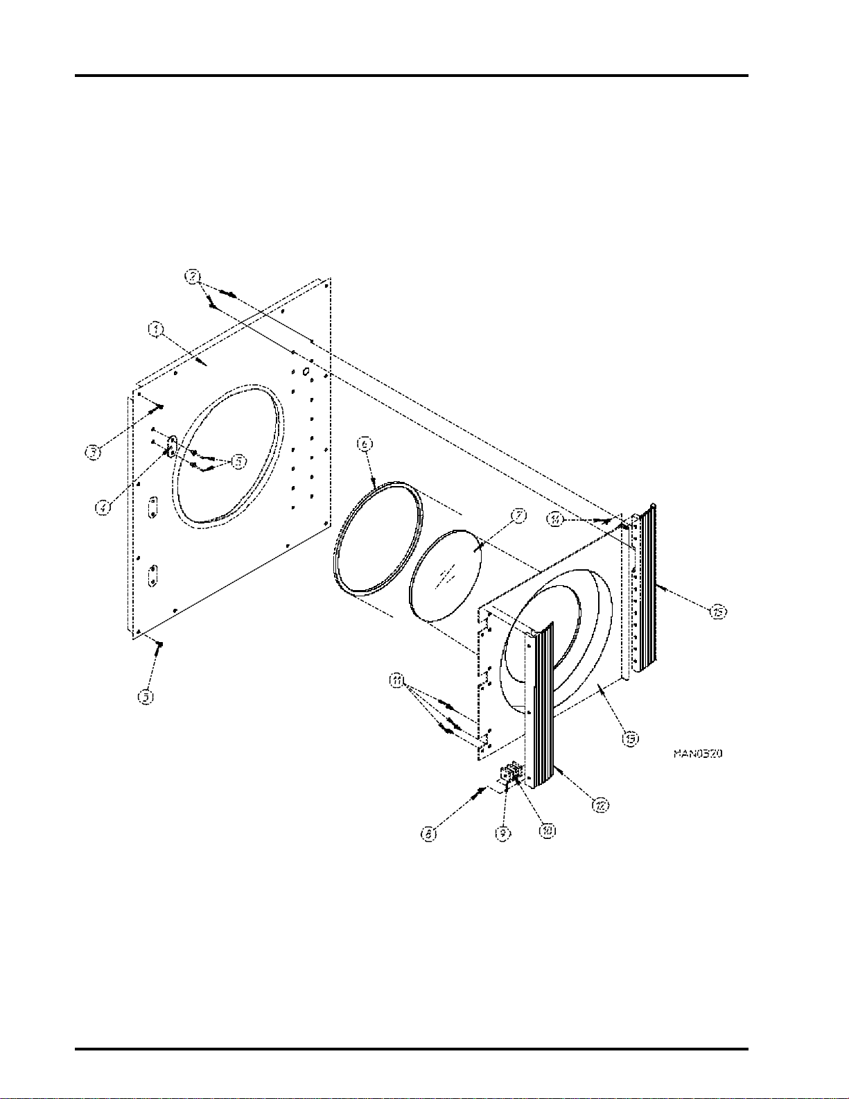
Electric Oven Element Structure
for 60 Kw 208/240 VAC Models mfd. prior to April 11, 1995
60 KW ELECTRIC OVEN ELEMENT STRUCTURE
(208/240V 3Ø 50/60 HZ)
75
ELEMENT ARRANGEMENT, INTERCONNECTIONS,
and LINE LEAD IDENTIFICATION
Page 78

76
American Dryer Corporation
88 Currant Road / Fall River, MA 02720-4781
Electric Oven Element Structure
for 60 Kw 380/416/480 VAC Models mfd. prior to April 11, 1995
60 KW ELECTRIC OVEN ELEMENT STRUCTURE
(380/416/480V 3Ø 50/60 HZ)
ELEMENT ARRANGEMENT, INTERCONNECTIONS,
and LINE LEAD IDENTIFICATION
Page 79

Telephone: (508) 678-9000
Fax: (508) 678-9447
Additional Parts Available
Part No. Description
112280 “Clean Lint Screen” Label
112534 “Phase 5 OPL Program Location Summary” Label
114006 “WARNING - Fire Hazards” Label
114041 “CAUTION - Exhaust/Lint Screen” Label
120100 3/8” Straight (BX) Connector
120300 3/8” x 45° (BX) Connector
120400 3/8” Red Jacket (BX) Insulator
120500 3/8” Jiffy Clip (BX Retainer Clip)
120600 3/8” Greenfield (BX)
120800 1/4” In-line Connector
120802 Red Butt Connector
120902 #74B Wire Nut
120903 Crimp-on Wire Nut
121014 1/4” Insulated (female) Terminal
121499 4” Harness Tie
121500 7” Harness Tie
121503 Harness Tie Mounting Clip
122804 Manometer (water column test gauge)
404502 White Brush-in-Cap Bottle Touch-Up Paint (0.6 oz. bottle)
401010 #847 Adhesive For Felt Collar
880200 Electrical Terminal (assortment) Kit
77
Page 80

ADC 450145 1- 07/15/94-50 2* 11/04/94-100 3* 07/21/95-100
4* 02/08/96-100 5* 01/30/98-50 6- 08/12/99-10
7- 08/17/99-15 8 - 06/13/00-15 9* 07/03/00-25
 Loading...