

Page 1
Service Procedures
for the
Model 20/31 Dryers
Electric and Hot Surface Ignitor Gas
American Dryer Corporation
88 Currant Road
Fall River MA 02720-4781 USA
Telephone: (508) 678-9000 / Fax: (508) 678-9447
e-mail: techsupport@amdry.com
www.amdry.com
ADC Part No. 450262
Page 2

Table of Contents
Part Locations and Removal ........................................ 3
Lower Front Panel Removal............................................................. 3
Upper Front Panel Removal............................................................. 3
T op Cover Removal ......................................................................... 3
Lint Box/Blower Assembly Removal................................................. 4
Gas V alve/Ignition System Removal................................................. 5
Oven Chamber Removal.................................................................. 5
Gas V alve/Ignition System Components........................................... 6
Oven Housing Components ............................................................. 6
Tumbler Support Wheel Assembly Replacement .............................. 6
Tumbler Alignment ........................................................................... 7
Belt Replacement ............................................................................ 6
Placing the Belt Back on the Motor Sheave...................................... 9
Electrical Component Locations ............................... 10
Electrical Panel.............................................................................. 10
Fire Suppression System Items, T erminal Block,
and Axial T emperature Probe......................................................... 11
Sail Switch Assembly..................................................................... 11
Exhaust Probe, Exhaust Hi-Limit, and Lint Drawer Switch .............. 11
Oven Contactor.............................................................................. 11
We have tried to make this manual as complete as possible and hope you will find it useful. ADC reserves the right to
make changes from time to time, without notice or obligation, in prices, specifications, colors, and material, and to
change or discontinue models. The illustrations included in this manual may not depict your particular dryer exactly.
Page 3
Part Locations and Removal
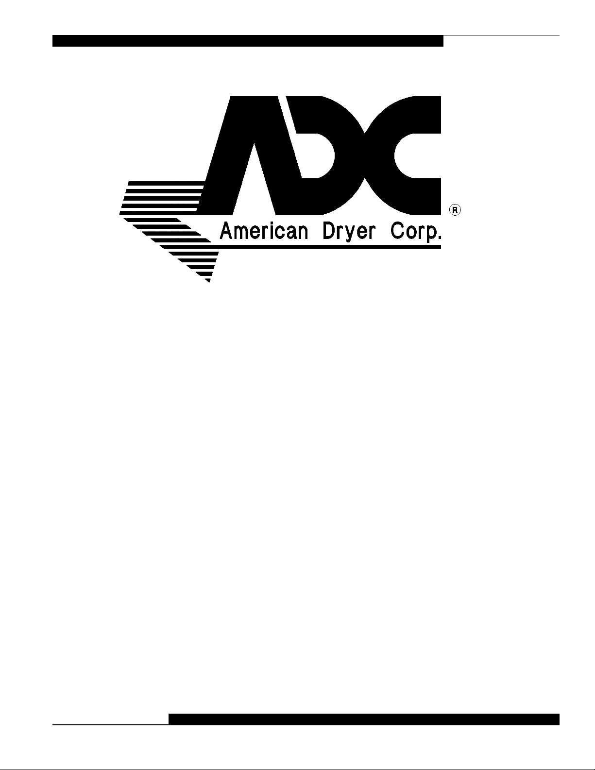
LOWER FRONT PANEL REMOVAL:
Remove the lint drawer. Remove the four screws
located just below the loading door. Tilt the top of
the panel out and lift the panel up and away from the
dryer.
TOP COVER REMOVAL:
First remove the back guard, then pull top cover
toward the rear of the dryer and lift up.
UPPER FRONT PANEL REMOVAL:
Remove the four screws located just above the
loading door. Tilt the bottom of the p anel out and lift
the panel up and away from the dryer .
450262-1 www.amdry.com 3
Page 4
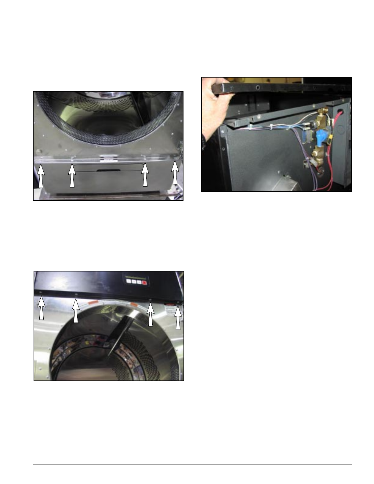
LINT BOX/BLOWER ASSEMBLY REMOVAL:
Remove screws and nuts at the rear of the lint box.
Unplug wires from the capacitor.
Remove two screws just above the lint drawer and
pull the lint box down from the front and out slightly .
T o remove motorized impellor assembly , remove the
five screws and four nuts, shown with arrows.
Remove cover and pull the motorized impellor
assembly out through the opening.
Unplug three connections at the left of the lint box.
The lint box may now be pulled out through the front
of the dryer.
4 American Dryer Corp. 450262-1
Page 5

GAS VALVE/IGNITION SYSTEM REMOVAL:
OVEN CHAMBER REMOVAL:
Be sure to shut off the gas main and then proceed
to remove electrical connections and screws
indicated. Remove lower front panel. Disconnect
union and screws noted with arrows.
The gas valve and burner orifice can now be carefully
pulled toward the front of the dryer.
Be sure to pull the assembly straight back so as not
to strike the very fragile carbon ignitor. With the
assembly partly out of the oven, the ignitor and the
two gas valve electrical connections can be
disconnected. At this point the assembly can be
removed from the dryer.
Replace assembly in the reverse order but make
sure the tab at the rear of the assembly engages
into the oven base slot.
Inspect all wires to be sure all lead directly toward
the front of the dryer. Be sure no wires are caught
on the burner tube or ignitor.
The oven chamber can be removed after the gas
valve/ignition system has been removed.
Remove the two screws indicated by the arrows.
Pull the oven housing part way out through the front
and disconnect all wire connections. The oven
housing can now be removed.
Replace assembly by leading the housing cone into
the hole in the rear wall. Replace screws and wire
connections.
450262-1 www.amdry.com 5
Page 6

GAS VALVE/IGNITION SYSTEM COMPONENTS
IGNITOR
BURNER TUBE
GAS VAL VE
OVEN HOUSING COMPONENTS
TUMBLER SUPPORT
WHEEL ASSEMBLY REPLACEMENT:
The front wheel assemblies can be replaced with
the lower front panel removed. Remove the three
bolts by reaching upward with a socket or box
wrench. The illustration below is provided to show
the location of these wheels as the wheels cannot
easily be seen while standing in front of the dryer .
HEA T SENSOR
OVEN CHAMBER
The left rear wheel assembly can be removed with
just the back guard removed. The rear right wheel
requires removing the back guard, heat duct, and
oven. Be sure to mark the position of rear wheel
brackets prior to removal (refer to page 7).
All wheel assemblies are mounted on slots to allow
for alignment of the tumbler. After one or more wheel
assemblies are replaced, the tumbler must be
realigned.
BURNER HIGH-LIMIT
6 American Dryer Corp. 450262-1
Page 7

TUMBLER ALIGNMENT:
EXAMPLES:
Proper alignment is achieved by making the gap
between the tumbler and openings in the front and
rear bulkheads equal on all sides.
The front to bulkhead may be checked for accuracy
by using a thickness gauge. The rear gap is not
accessible. Marking the position of the rear wheel
brackets before removing the brackets will help in
replacing the tumbler back into it’s original position
when the wheel brackets are reinstalled.
Below, both wheel assemblies must be moved to
the right in order to move the tumbler right. The left
wheel assembly must move a little more than the
right in order to lift the tumbler.
Adjust the tumbler position by loosening the three
bolts and forcing the wheel assembly toward the
center of the dryer to raise the tumbler and to move
it away from the side. A large screwdriver can
provide the necessary leverage. Adjustment of the
front of the tumbler is made by equalizing the gap
on the top, bottom, left and right by moving the wheel
assemblies.
Below, both wheel assemblies must be moved
inward in order to move the tumbler straight upward.
450262-1 www.amdry.com 7
Page 8

BELT REPLACEMENT
Shut off electrical power. Disconnect wiring leading to the tumbler support panel. Remove the back guard,
top, and the exhaust support bracket. Unbolt and remove the thrust washers from the rear of the tumbler
shaft. While someone holds the tumbler through the loading door remove all six screws from left and right
side of the rear tumbler support panel. Spread the right and left side panels at the top and pull the tumbler
support panel off of the dryer . Slip the new belt around the tumbler. Replace the rear tumbler support panel.
To maneuver the rear tumbler support panel back into position the rear wheels must be slipped under the
tumbler and the oven housing guided into the circular opening on the inner side of the tumbler support panel.
Replace the six tumbler support panel screws. Apply a few drop s of Loctite 290 to the thrust bearing bolt and
bolt the thrust washers back onto the tumbler shaft in the order shown. Place the belt back on the motor
sheave before replacing the exhaust support bracket, back guard, and top.
Note
A woodworker furniture clamp can be used
!
through the loading door to hold the
tumbler in place (refer to photo below). This will
allow the above procedure to be completed by one
person.
8 American Dryer Corp. 450262-1
Page 9

PLACING THE BELT BACK ON THE MOTOR SHEAVE:
REQUIRED ITEMS:
3 foot Section of 1-1/2” Electrical Tubing
Replacement Belt
To stretch the belt back onto the sheave involves using a two foot length of 1-1/2” electrical tubing (Fig. 1).
Preparing the end of the tubing as shown makes it easier to use. Position the belt around the tumbler and
directly above the motor sheave . Insert the tubing through the belt and onto the motor sheave (Fig. 2).
FIG . 1
FIG. 2
FIG . 3
While pushing the electrical tubing toward the motor, pull the end toward the bottom right corner (Fig. 3).
From this position, rotate the tubing clockwise. The belt will move to a position over the motor sheave. Hold
the belt against the motor (Fig. 3). Rotate the tubing one more revolution while pulling the tubing out. The belt
should drop onto the motor sheave. Rotate the tumbler a few turns while manually preventing the belt from
falling off the sheave. This should center the belt on the tumbler and prevent the belt from being thrown off
later. Replace all dryer panels.
450262-1 www.amdry.com 9
Page 10

Electrical Component Locations
ELECTRICAL PANEL:
The electrical panel is located behind the front upper panel.
DOOR SWITCH
MICROPROCESSOR
ROT ATION SENSOR
10 American Dryer Corp. 450262-1
Page 11

FIRE SUPPRESSION SYSTEM ITEMS,
TERMINAL BLOCK, AND AXIAL
TEMPERATURE PROBE
Located behind back guard.
PRESSURE SWITCH
AXIAL PROBE
SOLENOID VALVE
TERMINAL BLOCK
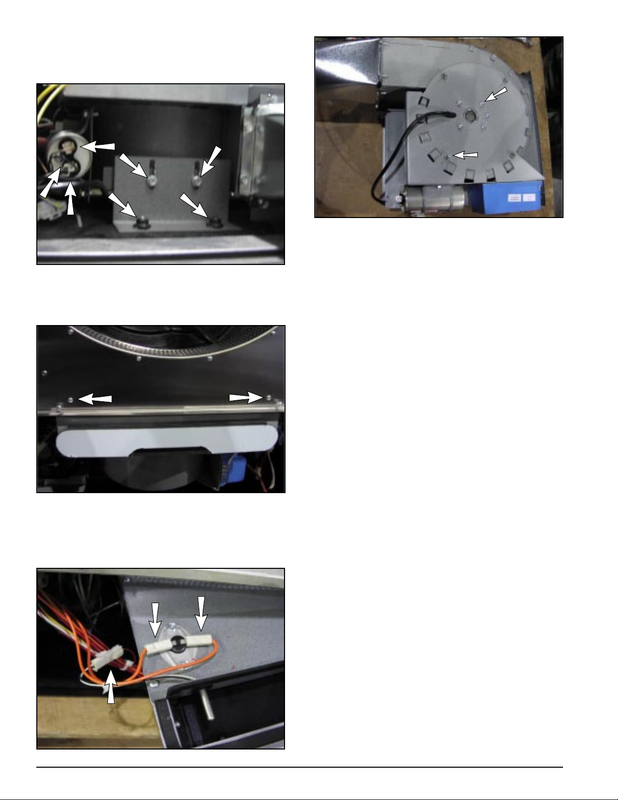
EXHAUST PROBE, EXHAUST HI-LIMIT,
AND LINT DRAWER SWITCH:
Temperature probe and exhaust hi-limit are
accessible once the lint box is removed. The lint
drawer switch can be removed after the cover has
been removed.
EXHAUST
HI-LIMIT SWITCH
EXHAUST TEMPERA TURE PROBE
LINT DRAWER SWITCH
SAIL SWITCH ASSEMBLY
Located behind back guard.
OVEN CONTACTOR:
Lower right front of the dryer (electric oven models).
ELECTRIC OVEN
OVEN CONT ACTOR
450262-1 www.amdry.com 11
Page 12

ADC Part No. 450262 1 - 02/25/05
 Loading...