

Page 1

XP-K7S748
AMD Socket A Processor Motherboard
User's Manual
M-040601
Page 2

Copyright Declaration
©2004 Gigatrend Technology Co., Ltd. All rights reserved. No part of this manual may be
reproduced, copied, translated, or transmitted in any form or by any means without express
permission from Gigatrend Technology. Companies and product names mentioned in this
document are trademarks or registered trademarks of their respective owners.
Legal Disclaimer
The information and content of this document is provided "as is", without warranty of any kind,
express or implied, including but not limited to the warranties of merchantability, fitness for a
particular purpose and non-infringement. Gigatrend Technology assumes no responsibility for
errors or omissions in this document or other documents which are referenced by or linked to
this document. The content of this document are subject to change without prior notice.
Gigatrend Technology may make improvements and/or changes in the product described in
this publication at any time and without prior notice. In no event shall Gigatrend Technology be
liable for any special, incidental, indirect or consequential damages of any kind arising out of
or in connection with the use or performance of this document. If you are uncertain about any
installation procedures, please consult a qualified computer technician.
Terms of Use
To avoid unnecessary errors of operation, please consult the user manual prior to hardware
installation. For more up-to-date information, please link to our company website at http://
www.axper.com
Prior to beginning installation procedures, please make sure that your computer turned off and
is connected to a grounded power outlet. If your system is not turned off during installation,
this could result in harm or damage to the motherboard, the components as well as to the
user.
Motherboard
XP-K7S748
Jul. 2, 2004
Motherboard
XP-K7S748
Jul. 2, 2004
Page 3

Contents
Motherboard Layout ........................................................................4
1. Production Introduction .............................................................5
1.1. Feature Summary .............................................................................. 5
1.2. I/O Back Panel and Connectors & Jumper Setting........................... 6
1.2.1. I/O Back Panel ...................................................................................... 6
1.2.2. Connectors & Jumper Setting .............................................................. 6
2. Hardware Installation ................................................................9
2.1. Installation of a Socket A CPU and Fan Sink .................................... 9
2.2. Installation of Memory ..................................................................... 10
2.3. Installation of the Graphics Card..................................................... 10
3. BIOS Setup............................................................................ 11
3.1. Setup Screen Features (BIOS version: E6).....................................11
3.2. Standard CMOS Features............................................................... 12
3.3. Advanced BIOS Features ............................................................... 14
3.4. Integrated Peripherals ..................................................................... 15
3.5. Power Management Setup.............................................................. 17
3.6. PnP/PCI Configuration .................................................................... 18
3.7. PC Health Status............................................................................. 19
3.8. Frequency/Voltage Control .............................................................. 20
3.9. Top Performance ............................................................................. 21
3.10. Load Fail-Safe Defaults................................................................... 21
3.11. Load Optimized Defaults ................................................................. 21
3.12. Set User Password.......................................................................... 21
3.13. Save & Exit Setup............................................................................ 21
3.14. Exit Without Saving ......................................................................... 22
4. Driver Installation....................................................................22
Page 4
English
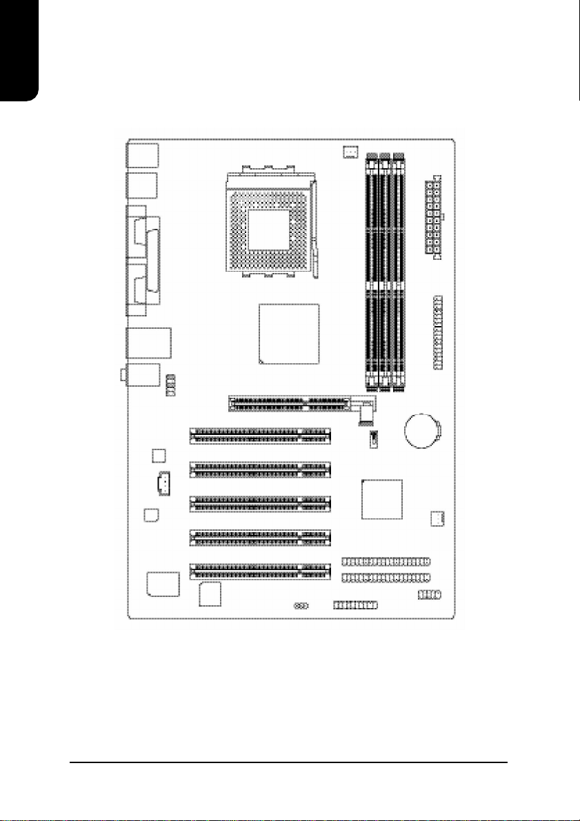
Motherboard Layout
KB_MS
USB
COMA
COMB
USB
AUDIO
CODEC
RTL8201
LPT
LAN
F_AUDIO
CD_IN
AGP
SOCKET A
SiS 748
CPU_FAN
PCI1
PCI2
PCI3
PCI4
XP-K7S748
DDR1
DDR2
DDR3
SW1
BATTERY
963L
ATX
FDD
SYS_FAN
IT8705F
BIOS
PWR_LED
PCI5
F_PANEL
IDE1
IDE2
F_USB
4
Page 5

1. Production Introduction
The user manual provides steps related to quick installation. If you wish to view complete
product information, please select the " ",Open User Manual button located on the driver
CD or link to our website at http://www.axper.com to received the most up-to-date information.
1.1. Feature Summary
CPU Socket A for AMD AthlonTM XP/AthlonTM/DuronTM processor
400/333/266MHz FSB
Supports 1.4GHz and faster
Chipset North Bridge: SiS 748
South Bridge: SiS 963L
Memory 3 184-pin DDR DIMM sockets, support up to 3GB DRAM (Max)
Supports DDR400/DDR333/DDR266 DIMM
Supports only 2.5V DDR SDRAM
Slots 1 AGP slot 4X/8X (1.5V) device support
5 PCI slots support 33MHz & PCI 2.2 compliant
On-Board IDE 2 IDE controller provide IDE HDD/CD-ROM(IDE1, IDE2) with PIO,
Bus Master (Ultra DMA33/ATA66/ATA100/ATA133) operation modes
Can connect up to 4 IDE devices
On-Board Floppy 1 Floppy port supports 2 FDD with 360K, 720K,1.2M, 1.44M and
2.88M bytes
On-Board Peripherals 1 Parallel port supports Normal/EPP/ECP mode
2 Serial port (COMA, COMB)
6 USB 2.0/1.1 ports (2 x Rear, 4 x Front by cable)
1 Front Audio connector
1 PS/2 Keyboard
1 PS/2 Mouse
On-Board LAN Builit-in RTL8201
1 RJ45 port
On-Board Sound ALC655 CODEC
Support 2/4/6 channel
Line Out / Line In / Mic In
CD In
BIOS Licensed AWARD BIOS
Supports BIOSNow!
I/O Control IT8705F
Hardware Monitor System voltage detect
CPU/System temperature detect
CPU/System fan revolution detect
CPU/System fan failure warning
CPU thermal shutdown function
Form Factor ATX size form factor, 30.5mm x 19.9mm
English
5
Page 6
English
1.2. I/O Back Panel and Connectors & Jumper Setting
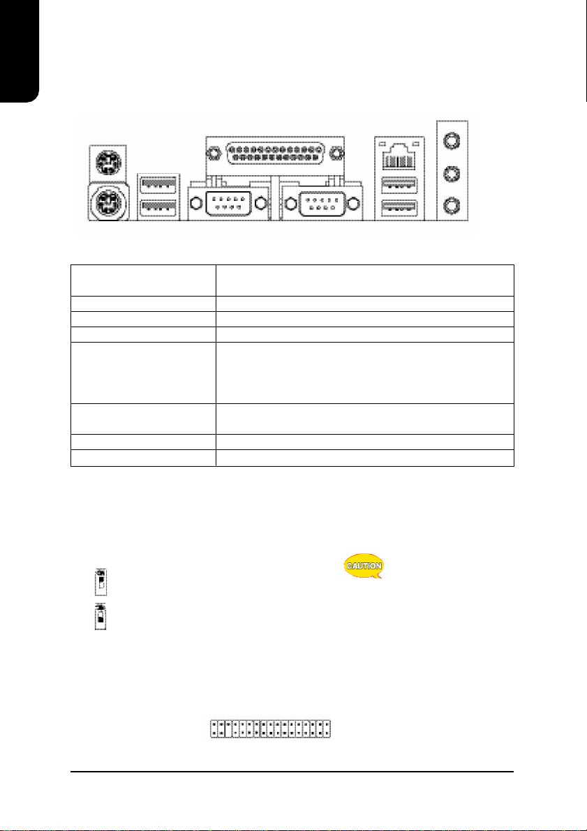
1.2.1. I/O Back Panel
PS/2 Mouse
Parallel Port
USB
LAN
Line In
Line Out
MIC In
PS/2 Keyboard
COM A
COM B
USB
PS/2 Keyboard / Connects PS/2 standard keyboard and PS/2 standard
PS/2 Mouse mouse
Parallel port (LPT) Connects to printer
COMA/COMB (Serial port) Connects to serial-based mouse or data processing devices
LAN (RJ45 LAN Port) Internet connection with speed of up to10/100Mbps
USB Prior to use, please make sure that your system as well
(Universal Serial Bus Port) as the connected attachments support the USB interface.
If driver installation is required, please consult the USB
section of the user manual.
Line In Connects to optical devices, CD players and other audio
input devices
LineOut Connects to speakers or headphones
Mic In Connects to microphone
1.2.2. Connectors & Jumper Setting
SW1 (System Jumper)
System clock can be adjusted to 100/133/166/200MHz. SW1 allows you to adjust the system
clock.
ON
ON: 100MHz (supports FSB 200MHz CPU, default)
OFF
ON
OFF: Auto (133/166/200MHz , supports FSB 266/333/
OFF
400MHz CPU)
If you are using a FSB
266MHz/333MHz or 400MHz
CPU, please set the jumper to
OFF (133/166/200MHz).
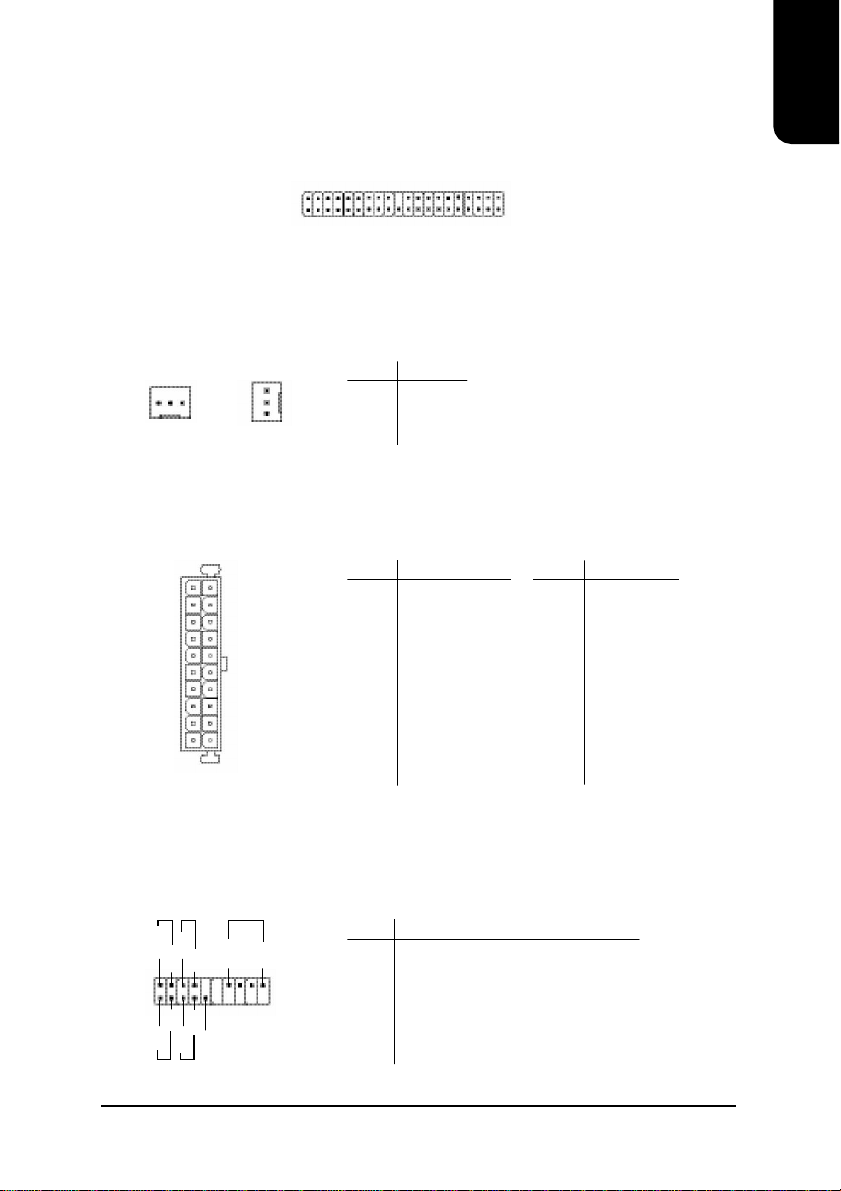
FDD (Floppy Disk Drive Connector)
The FDD connector is able to connect a single floppy disk drive via a FDD cable. Usually one
edge of the FDD cable is marked in red, please attach this marked edge to position 1 on the
connector.
1
6
342
33
Page 7
IDE1 / IDE2 (IDE1 and IDE2 Connector)
The IDE connector is able to connect two IDE devices via an IDE cable and requires checking
of the IDE jumper setting. It is recommended that the hard drive be connected to the first IDE
connector while the optical drive be connected to the second IDE connector.
2
1 39
40
CPU_FAN (CPU Fan Power Connector); SYS_FAN (System Fan Power Connector)
The CPU_Fan power connector provides the largest amount of power to the CPU fan at
600mA. You can connect the casing fan to the SYS_FAN connector to enhance system cooling.
English
CPU_FAN SYS_FAN
1
1
PIN SIGNAL
1 GND
2 +12V
3 Sense
ATX (ATX Power Connector)
The ATX power connector provides power to the motherboard. Prior to connection,
please make sure that the power supply is disconnected.
PIN SIGNAL
10
20
1 3.3V
2 3.3V
3 GND
4 VCC
5 GND
6 VCC
7 GND
8 Power Good
11
1
9 5VSB
(stand by +5V)
10 +12V
PIN SIGNAL
11 3.3V
12 -12V
13 GND
14 PS_ON
(soft on/off)
15 GND
16 GND
17 GND
18 -5V
19 VCC
20 VCC
F_PANEL (Front Panel Control Connector)
The F_Panel Control Connector connects to certain connectors on the front panel of the
system casing such as IDE Hard Disk Active LED, speaker, reset, and power on/off connectors.
You can use the schematic diagram below as the basis for connection.
PIN SIGNAL
PW+
MSG+
2
1
HD+
MSG-
HD-
RES-
PW-
RES+
SPK+
SPK-
20
19
NC
HD IDE Hard Disk Active LED
SPK Speaker Connector
RES Reset Switch
PW Power Switch
MSG Message LED/Power/Sleep LED
NC NC
7
Page 8

PWR_LED
English
Connects to the system power LED indicator whereby the power is indicated as ON or OFF.
However, the indicator will flash when the system is suspended.
F_AUDIO (Front Audio Connector)
Connects to the audio connector located on the front panel of the system casing (dependent
on case design). When use of the front panel audio connector is required, please remove the
5-6 pin, 9-10pin jumper. Please note that use of only the front panel audio connector or the
rear panel audio connector is permitted.
1
PIN SIGNAL
1 MPD+
2 MPD3 MPD-
PIN SIGNAL
9
10
1
2
1 MIC
2 GND
3 MIC_BIAS
4 POWER
5 Front Audio (R)
PIN SIGNAL
6 Rear Audio (R)
7 Reserved
8 NO PIN
9 Front Audio (L)
10 Rear Audio (L)
CD_IN (Optical Drive Audio Connector)
Connects CD-ROM or DVD-ROM audio connector.
1
PIN SIGNAL
1 CD_L
2 GND
3 GND
4 CD_R
F_USB (Front USB Connector)
Connects to the USB connector located on the front panel of the system casing (dependent on
case design). Note: Please make sure that each USB connection matches its designated
position. If connections are made incorrectly, the result can lead to inability to use the function
or even damage.
PIN SIGNAL
2
10
1
9
1 POWER
2 POWER
3 USB Dx4 USB Dy5 USB Dx+
PIN SIGNAL
6 USB Dy+
7 GND
8 GND
9 NO PIN
10 NC
8
Page 9

BATTERY (Battery)
The improper removal of the battery can result in harm. When replacing a battery, please
make sure you use one that is of similar brand and model number.
For information related to battery specifications and precautions, please
refer to the manufacturer instructions.
If you wish to delete the data stored in the CMOS, please follow the steps
below:
1. Please turn off your computer and unplug the power.
2. Remove the battery from the motherboard.
3. Wait 30 seconds and then replace the battery onto the motherboard.
4. Plug in the power supply and turn on your system.
2. Hardware Installation
1. Please make sure that the CPU used is supported by your motherboard.
2. Please be aware of the placement position of the CPU. If the CPU does not
insert properly, do not apply force but check the placement position.
3. Please make sure that an even layer of heat sink paste is added between the
CPU and the fan sink.
4. Please do not turn on the power prior to installing the fan sink. Doing so can
result in overheating and lead to permanent damage to the CPU.
5. Please follow the CPU specifications when setting the frequency. It is not
recommended that system speed settings exceed that of hardware
specifications. If you wish to set your system speed to exceed the recom
mended specifications, please check your hardware specifications eg: CPU,
graphics card, memory, hard drive
English
2.1. Installation of a Socket A CPU and Fan Sink
1
Note the small gold colored triangle on one corner of the CPU.
Place the triangle in the corner closest to the metal lever and
gently insert the CPU into its position.
A Socket A CPU has two indented
corners and these corners must be
properly positioned during installation.
2
When the CPU is inserted into its position, gently press the
metal lever downwards until a click is heard. Then add an
even layer of heat sink paste between the CPU and fan sink
for heat dissipation.
9
Page 10

English
do the same for the clips on the other end of
the fan sink.
2.2. Installation of Memory
The motherboard supports DIMM memory modules, whereby BIOS will automatically detect
memory capacity and specifications. Memory modules are designed so that they can be
inserted only in one direction.
3
Position and
attach the clips
on one end of
the fan sink
firmly atop the
CPU. Please
1. Before installing or removing memory, please make sure that the computer power
is turned off to prevent hardware damage.
2. Please make sure that the memory used is supported by the motherboard.
3. Memory modules have a foolproof insertion design. The memory can be in
stalled only when facing the correct position. If you cannot insert the module,
please switch directions.
4. It is recommended that memory of similar capacity, specifications and brand be
used.
1. Unfasten the clips on each end of the memory slots.
Correctly align the memory module in the slot and
push downwards..
4
Connect the 3pin cooler
power connector to the CPU
Fan connector
located on the
motherboard.
2. Once the memory module is correctly inserted, the
clips will automatically refasten. If the memory mod
ule is positioned in the wrong direction, it will not
insert. If this occurs, please switch directions.
2.3. Installation of the Graphics Card
1. Before installing the graphics card, please carefully
read the accompanying user manual. As well, make
sure the computer power is turned off.
2. Your graphics card must be 1.5V and support the
AGP4X specification.
3. When installing or removing the graphics card, first
pull out the white AGP knob before insertion or
removal. Releasing the AGP knob will hold the
graphics card firmly in place.
10
Page 11

English
3. BIOS Setup
BIOS (Basic Input and Output System) stores all the information of the motherboard settings
that is needed for system initiation within the CMOS. The CMOS SETUP utility allows the user
to make changes in BIOS configurations that are required or to activate certain features.
The CMOS SETUP saves each item configuration in the CMOS SRAM of the motherboard.
When the power is turned off, the battery on the motherboard supplies the required power to
the CMOS SRAM.
When the power is turned on, pushing the <Del> button during the BIOS POST (Power-On
Self Test) will bring up the CMOS SETUP screen. If you wish to enter the BIOS setup, please
press "Ctrl + F1" at the BIOS setup screen.
When using BIOS setup for the first time, it is recommended that you save the present BIOS
onto a disk in case you need to reset the BIOS back to its original settings. If you wish to
update to a new BIOS, the "BIOSNow!" can be used.
The user can select "BIOSNow!" as a way to quickly and easily update or back up BIOS
without entering the operating system.
3.1. Setup Screen Features (BIOS version: E6)
ø When you enter the CMOS SETUP screen, you will see the following screen and setting
selections as shown below.
CMOS Setup Utility-Copyright (C ) 1984-2004 Award Software
} Standard CMOS Features
} Advanced BIOS Features
} Integrated Peripherals
} Power Management Setup
} PnP/PCI Configurations
} PC Health Status
} Frequency /Voltage Control
ESC: Qu it higf: Select Item
F8: BIOSNow! F10: Save & Ex it Setup
Time, Date, Hard Disk Type...
T op Performance
Load Fail-Safe Defaults
Load Optimized Defaults
Set Sup ervisor Password
Set User Password
Save & Ex it Setup
Exit Without Saving
Instructions
< , , , , Enter> Movement in all four directions to highlight a desired option,
pressing <Enter> will select the option and take you to its
appropriate screen
<Page Up, Page Down> Used to toggle up and down the available options for a
particular item, whereby <Page Up> can also be used to
increase value option and <Page Down> to decrease
value option
<Esc> Return to main setup screen or exit setup
<F1> Gives the list of options available for each item
<F2> Gives the list of options available for the current item
<F5> Returns settings to previous values (not applicable to main setup
screen)
11
Page 12

<F6> Gives the list of options available for each item
English
<F7> Return to Optimized default values (not applicable to main
<F8> Enters BIOSNow! feature
<F9> Displays system information
<F10> Saves settings and exits setup
3.2. Standard CMOS Features
ø Includes the settings for items such as date, time, floppy disk drive specifications, and
setup screen)
hard drives connected to the IDE interface.
CMOS Setup Utility-Copyright (C ) 1984-2004 Award Software
Date (mm:dd:yy) Sat, May 15 2004
Time (hh:mm:ss) 22:31:24
} IDE Primary Master [None]
} IDE Primary Slave [None]
} IDE Secondary Master [None]
} IDE Secondary Slave [None]
Drive A [1.44M, 3.5"]
Drive B [Non e]
Floppy 3 Mode Supo rt [Disabled]
Holt On [All, But Keyboard]
Base Memory 640K
Extended Memory 127M
T otal Memory 128M
higf: Move Enter: Select +/-/PU/PD: Value F10: Save ESC: Exit F1: General Help
F5: Previous Values F6: Fail-Save Default F7: Optimized Defaults
Standard CMOS Features
Item Help
Menu Level}
Change the day, month,
year
<Week>
Sun. to Sat.
<Month>
Jan. to Dec.
<Day>
1 to 31 (or maximum
allowed in the month)
<Year>
1999 to 2098
n Date (mm:dd:yy)
Allows you to setup the date in the mm:dd:yy fashion.
n Time (hh:mm:ss)
Allows you to set up the date in the hh:mm:ss fashion. The time must be entered in the
24-hour format.
n IDE Primary Master(Slave) / IDE Secondary Master(Slave)
[IDE Device Setup]
IDE HDD Auto-Detection Press "Enter" to select this option for automatic device
detection.
IDE Primary Master(Slave) / IDE Secondary Master(Slave) IDE Device Setup. You can
use one of three methods:
Auto Allows BIOS to automatically detect IDE devices during POST(default)
None Select this if no IDE devices are used and the system will skip the
automatic detection step and allow for faster system start up.
Manual User can manually input the correct settings
Access Mode Use this to set the access mode for the hard drive. The four options are:
CHS/LBA/Large/Auto(default:Auto)
Hard drive information should be labeled on the outside drive casing. Enter the
appropriate option based on this information.
12
Page 13

English
n Floppy 3 Mode Support
Allows user to configure a Japanese standard 3 Mode floppy drive.
Options: Disabled (No 3 Mode drive installed)
Drive A (3 Mode Drive installed in A:)
Drive B (3 Mode Drive installed in B:)
Both (3 Mode Drive installed in A: and B:)
n Halt on
Tells the BIOS specifically which types of errors will halt the computer during the poweron self test (POST) section of the boot.
Options: No Errors (Never halt when an error is detected)
All Errors (Halt whenever an error is detected)
All, But Keyboard (Halt whenever an error is detected with the
exception of the keyboard)
All, But Diskette (Halt whenever an error is detected with the
exception of the diskette)
All, But Disk/Key (Halt whenever an error is detected with the
exception of the diskette and keyboard) (default:All, But Keyboard)
n Memory
When BIOS is displayed during POST, memory capacity is also displayed as shown
below:
Base Memory, Extended Memory, Total Memory (the user can verify the accuracy of
these values)
13
Page 14

English
ø Allows the configuration of advanced settings such as boot sequence, password
n First / Second / Third Boot Device
n Boot Up Floppy Seek
n Password Check
n Flexible AGP 8X
n Init Display First
3.3. Advanced BIOS Features
check, etc.
CMOS Setup Utility-Copyright (C ) 1984-2004 Award Software
First Boot Device [Floppy]
Second Boo t Device [HDD-0]
Third Boot Device [CDROM]
Boot Up Floppy Seek [Disabled]
Password Check [Setup ]
Flexible AGP 8X [Auto]
Init Display First [AGP]
higf: Move Enter: Select +/-/PU/PD: Value F10: Save ESC: Exit F1: General Help
F5: Previous Values F6: Fail-Save Default F7: Optimized Defaults
Advanced BIOS Features
Item Help
Menu Level}
Select Boo t Device
priority
[Floppy]
Boot from floppy
[LS120]
Boot fro m LS120
[HDD-0]
Boot from First HDD
[HDD-1]
Boot from Second HDD
The user can select the order in which the system will boot.
Options: Floppy, LS120,HDD-0~HDD3, SCSI, CDROM, ZIP,USB-FDD, USB-ZIP, USB-
CDROM, USB-HDD, LAN, Disabled
This feature controls whether the BIOS checks for a floppy drive while booting up.
(default:Disabled)
Allows user to set a password. To remove the password entry requirement, enter
SETUP and make sure there is no entry and then press <Enter>.
Options: System (Password entry is required during system start up and to enter
CMOS SETUP)
Setup (Password entry is required to enter CMOS SETUP)(default:Setup)
Allows user to set AGP card transfer rate.
Options: Auto, 4X (default:Auto)
Allows you to select whether to boot the system using the AGP graphics card or the PCI
graphics card.
Options: AGP (boot using AGP graphics card)
PCI(boot using PCI graphics card). (default: AGP)
14
Page 15

English
3.4. Integrated Peripherals
ø This menu allows you to control the various ports of the computer such as IDE, SATA,
USB, IEEE1394, COM port, LPT port, AC97 audio, etc.
CMOS Setup Utility-Copyright (C ) 1984-2004 Award Software
IDE1 Conducto r Cable [Auto]
IDE2 Conducto r Cable [Auto]
On-Chip Primary PC I IDE [Enabled]
On-Chip Secondary PCI IDE [Enabled]
AC97 Audio [Enabled]
Onboard LAN device [Enabled]
USB Contro ller [Enabled]
USB Legacy Suppo rt [Disabled]
Onboard Serial Port 1 [3F8/IRQ4]
Onboard Serial Port 2 [2F8/IRQ3]
Onboard Parallel Port [378/IRQ7]
Parallel Port Mode [SPP]
x ECP Mode Use DMA 3
Integrated Peripherals
Item Help
Menu Level}
[Auto]
Auto-d etect IDE
cable type
[ATA66/100/133]
Set conductor cable
to ATA66/100/133 (80
pins)
[ATA33]
Set conductor cable
to ATA33 (40 pins)
higf: Move Enter: Select +/-/PU/PD: Value F10: Save ESC: Exit F1: General Help
F5: Previous Values F6: Fail-Save Default F7: Optimized Defaults
n IDE1 Conductor Cable
Allows user to select the type of IDE1 conductor cable. Prior to selecting the setting,
please make sure that the IDE device and cables support the desired setting.
Options: Auto, ATA66/100, ATA33 (default:Auto)
n IDE2 Conductor Cable
Allows user to select the type of IDE2 conductor cable. Prior to selecting the setting,
please make sure that the IDE device and cables support the desired setting.
Options: Auto, ATA66/100, ATA33 (default:Auto)
n On-Chip Primary PCI IDE
Allows the user to enable or disable the first onboard IDE channel.
(default:Enabled)
n On-Chip Secondary PCI IDE
Allows the user to enable or disable the second onboard IDE channel.
(default:Enabled)
n AC97 Audio
Allows the user to use the onboard AC97 audio (default:Enabled)
n Onboard LAN device
Allows the user to enable or disable the onboard LAN (default:Enabled)
n USB Controller
Allows the user to enable or disable the onboard USB2.0 controller. (default:Enabled)
15
Page 16

n USB Legacy Support
English
n Onboard Serial Port 1
n Onboard Serial Port 2
n Onboard Parallel Port
n Parallel Mode
n ECP Mode Use DMA
Allows the user to use a USB keyboard or mouse. (default:Disabled)
Allows the user to enable or disable the first onboard serial port
Options: Auto, 3F8/IRQ4, 2F8/IRQ3, 3E8/IRQ4, 2E8/IRQ3, Disabled (default:3F8/IRQ4)
Allows the user to enable or disable the sectond onboard serial port
Options: Auto, 3F8/IRQ4, 2F8/IRQ3, 3E8/IRQ4, 2E8/IRQ3, Disabled (default:2F8/IRQ3)
Allows the user to enable or disable the onboard parallel port.
Options: 378/IRQ7, 278/IRQ5, 3BC/IRQ7, Disabled (default:378/IRQ7)
Use this to select the operation mode for the parallel port.
Options: SPP (normal)
EPP (Enhanced Parallel Port)
ECP (Extended Capabilities Port)
ECP+EPP (both ECP and EPP) (default:SPP)
Allows the user to select the ECP mode use DMA
Options: 3, 1 (default:3)
16
Page 17

English
3.5. Power Management Setup
ø This is used to control the various power saving features of the PC.
CMOS Setup Utility-Copyright (C ) 1984-2004 Award Software
ACPI Suspend Type [S1(POS)]
Soft-Off by PWR_BTTN [Off]
System After AC Back [Off]
IRQ [3-7, 9-15], NMI [Enabled]
ModemRingOn [Enabled]
PME Event Wake Up [Enabled]
Power On by Keyboard [Disabled]
Power On by Mou se [Disabled]
Resume by Alarm [Disabled]
x Month Alarm NA
x Day (of Month) Everyday
x Time (hh:mm:ss) 0 0 0
Power LED in S1 state [Blinking]
Power Management Setup
Item Help
Menu Level}
[S1]
Set suspend type to
Power On Susp end under
ACPI OS
[S3]
Set suspend type to
Suspend to RAM under
ACPI OS
higf: Move Enter: Select +/-/PU/PD: Value F10: Save ESC: Exit F1: General Help
F5: Previous Values F6: Fail-Save Default F7: Optimized Defaults
n ACPI Suspend Type
Allows user to select the Advanced Configuration and Power Interface(ACPI) as S1/POS
(Power On Suspend) or S3/STR(Suspend To RAM) (default:S1/POS)
n Soft-off by PWR_BTTN
Controls whether the PC shuts off immediately after hitting the power button or delaying
a few seconds. (default:Off)
Options: Off (PC shuts off immediately)
Suspend (Press power button 4 sec to power off. Enter suspend if button is
pressed less than 4 sec)
n System After AC BACK
Allows user to select system status when power is removed and returned.
Options: Off (Always in off state when AC back)
On (Always power on system when AC back)
Laststate (System power on depends on the status before AC lost)
(default:Off)
n IRQ [3-7, 9-15], NMI
When IRQ [3-7, 9-15] or NMI triggered, the suspend timer will be reloaded to prevent
system gets into green mode. (default:Enabled)
n ModemRingOn
To use this feature, an Ethernet card supporting the PCI2.2 or newer standard must be
used. (default:Enabled)
n PME Event Wake Up
Allows user to select the Power Management Event (PME) wake up function which
requires the system to have a +5VSB power supply using a rate of 1A or less.
(default:Enabled)
17
Page 18

n Power On by Keyboard
English
n Power On by Mouse
n Resume by Alarm
n Power LED in S1 state
3.6. PnP/PCI Configuration
ø This menu allows you to configure your PCI slots. You can assign IRQ's for various PCI
Allows user to turn on system using the keyboard.
Options: Password (input an 8 character long password)
Any Key (power on by any key)
Disabled (default:Disabled)
Allows user to turn on system using the mouse. (default:Disabled)
If set to Enabled, the user can set the date and time for automatic system power-on.
(default:Disabled)
Settings:
Month Alarm : NA, 1~12
Date (of Month) Alarm : Everyday, 1~31
Time (hh: mm: ss) Alarm : (0~23) : (0~59) : (0~59)
Allows user to select the system LED status in the S1 (POS - Power On Suspend) state.
Options: Blinking (LED will blink)
Dual/OFF (When selecting this, the LED will turn off for a single-colored LED
or change color for a dual-colored LED)(default:Blinking)
slots.
PCI4 IRQ Assignment [Auto]
PCI1/PCI5 IRQ Assignment [Auto]
PCI2 IRQ Assignment [Auto]
PCI3 IRQ Assignment [Auto]
CMOS Setup Utility-Copyright (C ) 1984-2004 Award Software
PnP/PCI Configurations
Item Help
Menu Level}
Device(s) using this
INT:
Display Cntrlr
-Bus 1 Dev 0 Func 0
higf: Move Enter: Select +/-/PU/PD: Value F10: Save ESC: Exit F1: General Help
F5: Previous Values F6: Fail-Save Default F7: Optimized Defaults
n PCI4 IRQ Assignment
Allows you to assign an IRQ for the fourth PCI slot. Options:Auto,3,4,5,7,9,10,11,12,14,
15 (default:Auto)
n PCI1/PCI5 IRQ Assignment
Allows you to assign an IRQ for the first/fifth PCI slot. Options:Auto,3,4,5,7,9,10,11,12,14,
15 (default:Auto)
18
Page 19

English
n PCI2 IRQ Assignment
Allows you to assign an IRQ for the second PCI slot. Options:Auto,3,4,5,7,9,10,11,12,14,
15 (default:Auto)
n PCI3 IRQ Assignment
Allows you to assign an IRQ for the third PCI slot. Options:Auto,3,4,5,7,9,10,11,12,14,15
(default:Auto)
3.7. PC Health Status
ø This menu displays the current CPU temperature, the fan speeds, voltages etc.
CMOS Setup Utility-Copyright (C ) 1984-2004 Award Software
Vcore OK
DDR25 OK
+3.3V OK
+12V OK
Curren t CPU Temperature 47°C
Current CPU FAN Speed 4687 RPM
Current System FAN Speed 0 RPM
PC Health Status
Item Help
Menu Level}
higf: Move Enter: Select +/-/PU/PD: Value F10: Save ESC: Exit F1: General Help
F5: Previous Values F6: Fail-Save Default F7: Optimized Defaults
n Current Voltage(V) Vcore / DDR25 / +3.3V / +12V
Automatically checks system voltage
n Current CPU Temperature
Automatically checks CPU temperature
n Current CPU/System FAN Speed (RPM)
Automatically checks CPU/System fan speed
19
Page 20

English
ø This allows user to configure CPU frequency and voltage settings.
3.8. Frequency/Voltage Control
CMOS Setup Utility-Copyright (C ) 1984-2004 Award Software
Linear Frequency Control [Disabled]
ø CPU Clock(MHz) 100
ø DRAM Clock(MHz) AUTO
AGP Voltage Control [Normal]
DRAM Voltage Control [Normal]
CPU Voltage Control [Normal]
Frequency /Voltage Control
Item Help
Menu Level}
higf: Move Enter: Select +/-/PU/PD: Value F10: Save ESC: Exit F1: General Help
F5: Previous Values F6: Fail-Save Default F7: Optimized Defaults
ø This section is very dangerous for inexperienced users, and therefore it is not
recommended that these settings be altered. An incorrect setting can result in system
instability, corrupt data, or permanent hardware damage.
n Linear Frequency Control
Allows user to use Linear Frequency Control (default:Disabled)
n CPU Clock (MHz)
If you wish to use this feature, please set the "Linear Frequency Control" to Enabled. If this
feature is disabled, the currently CPU frequency will be displayed.
The CPU Clock can be input between 100MHz to 355MHz.
n DRAM Clock (MHz)
Allows user to adjust the DRAM clock frequency. (default:Auto)
Please note that if the DRAM clock frequency is incorrectly set, the system will be unable
to start. You can use the clear CMOS method to return the system to its default settings.
n AGP Voltage Control
Allows user to set the AGP voltage. (default:Normal)
Please note that by overclocking your system through the increase of the AGP voltage,
system instability or damage to the AGP card may occur.
Options: Normal (automatic setting of AGP voltage at 1.5V)
+0.1V (AGP voltage range)
n DRAM Voltage Control
Allows user to set the DIMM voltage. (default:Normal)
Please note that by overclocking your system through the increase of the DIMM voltage,
damage to the memory may occur.
Options: Normal (automatic setting of DIMM voltage at 2.5V)
+0.1V (DIMM voltage range)
20
Page 21

English
n CPU Voltage Control
Allows user to set the CPU voltage. (default:Normal)
Please note that by overclocking your system through the increase of the CPU voltage,
system instability or damage to the CPU may occur.
Options: Normal (automatic setting of CPU voltage as CPU required)
+5%, +7.5%, +10% (CPU voltage range)
3.9. Top Performance
ø "Top Performance" allows faster system start. However, the result may differ depending
on system specifications (includes hardware and OS). For example, certain hardware
may become unstable under Windows XP but work reliably under the Windows NT
operating system. Thus, select Disabled under "Top Performance" if system hardware is
affected.
3.10. Load Fail-Safe Defaults
ø Use this option to reset your BIOS settings to the system defaults. You should only use
this if you are encountering serious problems.
Please select <Y> and <Enter> to load Fail-Safe defaults. Once this is loaded, your
system may be slowed since this uses a minimal performance setting to allow stable
system running.
3.11. Load Optimized Defaults
ø Like the Fail-Safe mode above, this option loads the BIOS default settings, but runs the
system at optimal performance.
Please select <Y> and <Enter> to load optimized defaults.
3.12. Set User Password
ø Use this to set the password that is needed to either enter into the BIOS or to boot the
system. Entering in a blank field will disable the password.
Please input an 8 character long password and then select Enter. You will be required
to re-enter the password for confirmation. If you wish to remove the need for password
entry, leave the entry blank and then select Enter. BIOS will then display "PASSWORD
DISABLED". Once you have completed the password setting, you will need to go to
"Advanced BIOS Features" and select "Password Check" for setup of password check.
3.13. Save & Exit Setup
ø To save any changes you made to the BIOS you must choose this option. The
system will automatically exit setup and perform a system restart. Pushing <F10> will
have the same effect.
Push <Y> and <Enter> to save and exit setup. If you do not wish to save, select <N> or
<Esc> to return to the main menu.
21
Page 22

English
ø Use this option instead of the one above if you wish to exit the BIOS without saving the
4. Driver Installation
Driver installation for the Windows 98/98SE/200/ME/XP operating systems is simple. Once
you insert the provided driver disks into your optical drive, the AUTORUN screen will appear.
If this screen does not appear, you can use "D:\setup.exe" (with "D" being the specified drive)
to bring up the screen shown below. Just follow the screen instructions to easily complete
driver installation.
3.14. Exit Without Saving
changes you have made. Pushing <ESC> will have the same effect.
Push <Y> and <Enter> to exit setup. You can return to the main menu by pushing <N> or
<Esc>.
Open User Manual
Display system information
Open Readme File
Browse CD
Contact Us
22
axper Install - Displays required driver installation, select "Go" for
automatic installation
Customize Installation - Allows specific choice of drivers for installation
axper Utilities - Displays axper's unique utilities
Software - Displays the required software
 Loading...