

System V App Binary Interface AMD64 Architecture Processor Supplement. [rev.0.99].[2007-12]
Table of contents
 Loading...
AMD System V App Binary Interface AMD64 Architecture Processor Supplement. [rev.0.99].[2007-12] Datasheet
Page 1

System V Application Binary Interface
AMD64 Architecture Processor Supplement
Draft Version 0.99
Edited by
Michael Matz1, Jan Hubiˇcka2, Andreas Jaeger3, Mark Mitchell
December 7, 2007
4
1
2
3
4
AMD64 ABI Draft 0.99 – December 7, 2007 – 4:39
Page 2

Contents
1 Introduction 8
2 Software Installation 9
3 Low Level System Information 10
3.1 Machine Interface . . . . . . . . . . . . . . . . . . . . . . . . . . 10
3.1.1 Processor Architecture . . . . . . . . . . . . . . . . . . . 10
3.1.2 Data Representation . . . . . . . . . . . . . . . . . . . . 10
3.2 Function Calling Sequence . . . . . . . . . . . . . . . . . . . . . 13
3.2.1 Registers and the Stack Frame . . . . . . . . . . . . . . . 14
3.2.2 The Stack Frame . . . . . . . . . . . . . . . . . . . . . . 14
3.2.3 Parameter Passing . . . . . . . . . . . . . . . . . . . . . 15
3.3 Operating System Interface . . . . . . . . . . . . . . . . . . . . . 22
3.3.1 Exception Interface . . . . . . . . . . . . . . . . . . . . . 22
3.3.2 Virtual Address Space . . . . . . . . . . . . . . . . . . . 22
3.3.3 Page Size . . . . . . . . . . . . . . . . . . . . . . . . . . 24
3.3.4 Virtual Address Assignments . . . . . . . . . . . . . . . . 24
3.4 Process Initialization . . . . . . . . . . . . . . . . . . . . . . . . 25
3.4.1 Initial Stack and Register State . . . . . . . . . . . . . . . 25
3.4.2 Thread State . . . . . . . . . . . . . . . . . . . . . . . . 29
3.4.3 Auxiliary Vector . . . . . . . . . . . . . . . . . . . . . . 29
3.5 Coding Examples . . . . . . . . . . . . . . . . . . . . . . . . . . 31
3.5.1 Architectural Constraints . . . . . . . . . . . . . . . . . . 32
3.5.2 Conventions . . . . . . . . . . . . . . . . . . . . . . . . 34
3.5.3 Position-Independent Function Prologue . . . . . . . . . . 35
3.5.4 Data Objects . . . . . . . . . . . . . . . . . . . . . . . . 36
3.5.5 Function Calls . . . . . . . . . . . . . . . . . . . . . . . 44
3.5.6 Branching . . . . . . . . . . . . . . . . . . . . . . . . . . 46
1
AMD64 ABI Draft 0.99 – December 7, 2007 – 4:39
Page 3

3.5.7 Variable Argument Lists . . . . . . . . . . . . . . . . . . 49
3.6 DWARF Definition . . . . . . . . . . . . . . . . . . . . . . . . . 54
3.6.1 DWARF Release Number . . . . . . . . . . . . . . . . . 54
3.6.2 DWARF Register Number Mapping . . . . . . . . . . . . 54
3.7 Stack Unwind Algorithm . . . . . . . . . . . . . . . . . . . . . . 54
4 Object Files 58
4.1 ELF Header . . . . . . . . . . . . . . . . . . . . . . . . . . . . . 58
4.1.1 Machine Information . . . . . . . . . . . . . . . . . . . . 58
4.1.2 Number of Program Headers . . . . . . . . . . . . . . . . 58
4.2 Sections . . . . . . . . . . . . . . . . . . . . . . . . . . . . . . . 59
4.2.1 Section Flags . . . . . . . . . . . . . . . . . . . . . . . . 59
4.2.2 Section types . . . . . . . . . . . . . . . . . . . . . . . . 60
4.2.3 Special Sections . . . . . . . . . . . . . . . . . . . . . . 60
4.2.4 EH_FRAME sections . . . . . . . . . . . . . . . . . . . 61
4.3 Symbol Table . . . . . . . . . . . . . . . . . . . . . . . . . . . . 66
4.4 Relocation . . . . . . . . . . . . . . . . . . . . . . . . . . . . . . 66
4.4.1 Relocation Types . . . . . . . . . . . . . . . . . . . . . . 66
4.4.2 Large Models . . . . . . . . . . . . . . . . . . . . . . . . 71
5 Program Loading and Dynamic Linking 73
5.1 Program Loading . . . . . . . . . . . . . . . . . . . . . . . . . . 73
5.1.1 Program header . . . . . . . . . . . . . . . . . . . . . . . 74
5.2 Dynamic Linking . . . . . . . . . . . . . . . . . . . . . . . . . . 74
5.2.1 Program Interpreter . . . . . . . . . . . . . . . . . . . . . 81
5.2.2 Initialization and Termination Functions . . . . . . . . . . 81
6 Libraries 82
6.1 C Library . . . . . . . . . . . . . . . . . . . . . . . . . . . . . . 82
6.1.1 Global Data Symbols . . . . . . . . . . . . . . . . . . . . 82
6.1.2 Floating Point Environment Functions . . . . . . . . . . . 82
6.2 Unwind Library Interface . . . . . . . . . . . . . . . . . . . . . . 83
6.2.1 Exception Handler Framework . . . . . . . . . . . . . . . 84
6.2.2 Data Structures . . . . . . . . . . . . . . . . . . . . . . . 86
6.2.3 Throwing an Exception . . . . . . . . . . . . . . . . . . . 88
6.2.4 Exception Object Management . . . . . . . . . . . . . . . 91
6.2.5 Context Management . . . . . . . . . . . . . . . . . . . . 91
6.2.6 Personality Routine . . . . . . . . . . . . . . . . . . . . . 94
2
AMD64 ABI Draft 0.99 – December 7, 2007 – 4:39
Page 4

6.3 Unwinding Through Assembler Code . . . . . . . . . . . . . . . 98
7 Development Environment 101
8 Execution Environment 102
9 Conventions 103
9.1 C++ . . . . . . . . . . . . . . . . . . . . . . . . . . . . . . . . . 104
9.2 Fortran . . . . . . . . . . . . . . . . . . . . . . . . . . . . . . . . 105
9.2.1 Names . . . . . . . . . . . . . . . . . . . . . . . . . . . 105
9.2.2 Representation of Fortran Types . . . . . . . . . . . . . . 106
9.2.3 Argument Passing . . . . . . . . . . . . . . . . . . . . . 107
9.2.4 Functions . . . . . . . . . . . . . . . . . . . . . . . . . . 108
9.2.5 COMMON blocks . . . . . . . . . . . . . . . . . . . . . 109
9.2.6 Intrinsics . . . . . . . . . . . . . . . . . . . . . . . . . . 110
A Linux Conventions 121
A.1 Execution of 32-bit Programs . . . . . . . . . . . . . . . . . . . . 121
A.2 AMD64 Linux Kernel Conventions . . . . . . . . . . . . . . . . . 121
A.2.1 Calling Conventions . . . . . . . . . . . . . . . . . . . . 121
A.2.2 Stack Layout . . . . . . . . . . . . . . . . . . . . . . . . 122
A.2.3 Required Processor Features . . . . . . . . . . . . . . . . 122
A.2.4 Miscellaneous Remarks . . . . . . . . . . . . . . . . . . 122
3
AMD64 ABI Draft 0.99 – December 7, 2007 – 4:39
Page 5

List of Tables
3.1 Hardware Exceptions and Signals . . . . . . . . . . . . . . . . . 23
3.2 Floating-Point Exceptions . . . . . . . . . . . . . . . . . . . . . 23
3.3 x87 Floating-Point Control Word . . . . . . . . . . . . . . . . . . 26
3.4 MXCSR Status Bits . . . . . . . . . . . . . . . . . . . . . . . . . 26
3.5 rFLAGS Bits . . . . . . . . . . . . . . . . . . . . . . . . . . . . 27
4.1 AMD64 Identification . . . . . . . . . . . . . . . . . . . . . . . . 58
4.2 AMD64 Specific Section Header Flag, sh_flags . . . . . . . . 59
4.3 Section Header Types . . . . . . . . . . . . . . . . . . . . . . . . 60
4.4 Special sections . . . . . . . . . . . . . . . . . . . . . . . . . . . 60
4.5 Additional Special Sections for the Large Code Model . . . . . . 61
4.6 Common Information Entry (CIE) . . . . . . . . . . . . . . . . . 63
4.7 CIE Augmentation Section Content . . . . . . . . . . . . . . . . 64
4.8 Frame Descriptor Entry (FDE) . . . . . . . . . . . . . . . . . . . 65
4.9 FDE Augmentation Section Content . . . . . . . . . . . . . . . . 66
4.10 Relocation Types . . . . . . . . . . . . . . . . . . . . . . . . . . 69
4.11 Large Model Relocation Types . . . . . . . . . . . . . . . . . . . 72
5.1 Program Header Types . . . . . . . . . . . . . . . . . . . . . . . 74
7.1 Predefined Pre-Processor Symbols . . . . . . . . . . . . . . . . . 101
9.1 Mil intrinsics . . . . . . . . . . . . . . . . . . . . . . . . . . . . 111
9.2 F77 intrinsics . . . . . . . . . . . . . . . . . . . . . . . . . . . . 113
9.3 F90 intrinsics . . . . . . . . . . . . . . . . . . . . . . . . . . . . 114
9.4 Math intrinsics . . . . . . . . . . . . . . . . . . . . . . . . . . . 114
9.5 Unix intrinsics . . . . . . . . . . . . . . . . . . . . . . . . . . . . 116
A.1 Required Processor Features . . . . . . . . . . . . . . . . . . . . 123
4
AMD64 ABI Draft 0.99 – December 7, 2007 – 4:39
Page 6

List of Figures
3.1 Scalar Types . . . . . . . . . . . . . . . . . . . . . . . . . . . . . 11
3.2 Bit-Field Ranges . . . . . . . . . . . . . . . . . . . . . . . . . . 13
3.3 Stack Frame with Base Pointer . . . . . . . . . . . . . . . . . . . 15
3.4 Register Usage . . . . . . . . . . . . . . . . . . . . . . . . . . . 20
3.5 Parameter Passing Example . . . . . . . . . . . . . . . . . . . . . 21
3.6 Register Allocation Example . . . . . . . . . . . . . . . . . . . . 22
3.7 Virtual Address Configuration . . . . . . . . . . . . . . . . . . . 24
3.8 Conventional Segment Arrangements . . . . . . . . . . . . . . . 25
3.9 Initial Process Stack . . . . . . . . . . . . . . . . . . . . . . . . . 28
3.10 auxv_t Type Definition . . . . . . . . . . . . . . . . . . . . . . 29
3.11 Auxiliary Vector Types . . . . . . . . . . . . . . . . . . . . . . . 30
3.12 Position-Independent Function Prolog Code . . . . . . . . . . . . 35
3.13 Absolute Load and Store (Small Model) . . . . . . . . . . . . . . 37
3.14 Position-Independent Load and Store (Small PIC Model) . . . . . 38
3.15 Absolute Load and Store (Medium Model) . . . . . . . . . . . . . 39
3.16 Position-Independent Load and Store (Medium PIC Model) . . . . 40
3.17 Position-Independent Load and Store (Medium PIC Model), con-
tinued . . . . . . . . . . . . . . . . . . . . . . . . . . . . . . . . 41
3.18 Absolute Global Data Load and Store . . . . . . . . . . . . . . . 42
3.19 Faster Absolute Global Data Load and Store . . . . . . . . . . . . 42
3.20 Position-Independent Global Data Load and Store . . . . . . . . . 43
3.21 Faster Position-Independent Global Data Load and Store . . . . . 43
3.22 Position-Independent Direct Function Call (Small and Medium
Model) . . . . . . . . . . . . . . . . . . . . . . . . . . . . . . . . 44
3.23 Position-Independent Indirect Function Call . . . . . . . . . . . . 44
3.24 Absolute Direct and Indirect Function Call . . . . . . . . . . . . . 45
3.25 Position-Independent Direct and Indirect Function Call . . . . . . 45
3.26 Absolute Branching Code . . . . . . . . . . . . . . . . . . . . . . 47
5
AMD64 ABI Draft 0.99 – December 7, 2007 – 4:39
Page 7

3.27 Implicit Calculation of Target Address . . . . . . . . . . . . . . . 47
3.28 Position-Independent Branching Code . . . . . . . . . . . . . . . 48
3.29 Absolute Switch Code . . . . . . . . . . . . . . . . . . . . . . . 48
3.30 Position-Independent Switch Code . . . . . . . . . . . . . . . . . 49
3.31 Parameter Passing Example with Variable-Argument List . . . . . 50
3.32 Register Allocation Example for Variable-Argument List . . . . . 50
3.33 Register Save Area . . . . . . . . . . . . . . . . . . . . . . . . . 51
3.34 va_list Type Declaration . . . . . . . . . . . . . . . . . . . . 51
3.35 Sample Implementation of va_arg(l, int) . . . . . . . . . . 53
3.36 DWARF Register Number Mapping . . . . . . . . . . . . . . . . 55
3.37 Pointer Encoding Specification Byte . . . . . . . . . . . . . . . . 57
4.1 Relocatable Fields . . . . . . . . . . . . . . . . . . . . . . . . . . 67
5.1 Global Offset Table . . . . . . . . . . . . . . . . . . . . . . . . . 75
5.2 Procedure Linkage Table (small and medium models) . . . . . . . 77
5.3 Final Large Code Model PLT . . . . . . . . . . . . . . . . . . . . 80
6.1 Examples for Unwinding in Assembler . . . . . . . . . . . . . . . 100
9.1 Example mapping of names . . . . . . . . . . . . . . . . . . . . . 106
9.2 Mapping of Fortran to C types . . . . . . . . . . . . . . . . . . . 106
Revision History
0.99 Add description of TLS relocations (thanks to Alexandre Oliva) and mention
the decimal floating point types (thanks to H.J. Lu).
0.98 Various clarifications and fixes according to feedback from Sun, thanks to
Terrence Miller. DWARF register numbers for some system registers, thanks
to Jan Beulich. Add R_X86_64_SIZE32 and R_X86_64_SIZE64 relocations; extend meaning of e_phnum to handle more than 0xffff program
headers, thanks to Rod Evans. Add footnote about passing of decimal
datatypes. Specify that _Bool is booleanized at the caller.
0.97 Integrate Fortran ABI.
0.96 Use SHF_X86_64_LARGE instead SHF_AMD64_LARGE (thanks to Evan-
dro Menezes). Correct various grammatical errors noted by Mark F. Haigh,
6
AMD64 ABI Draft 0.99 – December 7, 2007 – 4:39
Page 8

who also noted that there are no global VLAs in C99. Thanks also to Robert
R. Henry.
0.95 Include description of the medium PIC memory model (thanks to Jan Hubiˇcka) and large model (thanks to Evandro Menezes).
0.94 Add sections in Development Environment, Program Loading, a description
of EH_FRAME sections and general cleanups to make text in this ABI selfcontained. Thanks to Michael Walker and Terrence Miller.
0.93 Add sections about program headers, new section types and special sections
for unwinding information. Thanks to Michael Walker.
0.92 Fix some typos (thanks to Bryan Ford), add section about stack layout in the
Linux kernel. Fix example in figure 3.5 (thanks to Tom Horsley). Add section on unwinding through assembler (written by Michal Ludvig). Remove
mmxext feature (thanks to Evandro Menezes). Add section on Fortran (by
Steven Bosscher) and stack unwinding (by Jan Hubiˇcka).
0.91 Clarify that x87 is default mode, not MMX (by Hans Peter Anvin).
0.90 Change DWARF register numbers again; mention that __m128 needs align-
ment; fix typo in figure 3.3; add some comments on kernel expectations;
mention TLS extensions; add example for passing of variable-argument
lists; change semantics of %rax in variable-argument lists; improve formatting; mention that X87 class is not used for passing; make /lib64 a
Linux specific section; rename x86-64 to AMD64; describe passing of complex types. Special thanks to Andi Kleen, Michal Ludvig, Michael Matz,
David O’Brien and Eric Young for their comments.
0.21 Define __int128 as class INTEGER in register passing. Mention that
%al is used for variadic argument lists. Fix some textual problems. Thanks
to H. Peter Anvin, Bo Thorsen, and Michael Matz.
0.20 — 2002-07-11 Change DWARF register number values of %rbx, %rsi,
%rsi (thanks to Michal Ludvig). Fix footnotes for fundamental types
(thanks to H. Peter Anvin). Specify size_t (thanks to Bo Thorsen and
Andreas Schwab). Add new section on floating point environment functions.
7
AMD64 ABI Draft 0.99 – December 7, 2007 – 4:39
Page 9

0.19 — 2002-03-27 Set name of Linux dynamic linker, mention %fs. Incorpo-
rate changes from H. Peter Anvin <[email protected]> for booleans and define handling of sub-64-bit integer types in registers.
8
AMD64 ABI Draft 0.99 – December 7, 2007 – 4:39
Page 10

Chapter 1
Introduction
The AMD641architecture2is an extension of the x86 architecture. Any processor
implementing the AMD64 architecture specification will also provide compatibility modes for previous descendants of the Intel 8086 architecture, including 32-bit
processors such as the Intel 386, Intel Pentium, and AMD K6-2 processor. Operating systems conforming to the AMD64 ABI may provide support for executing
programs that are designed to execute in these compatibility modes. The AMD64
ABI does not apply to such programs; this document applies only programs running in the “long” mode provided by the AMD64 architecture.
Except where otherwise noted, the AMD64 architecture ABI follows the conventions described in the Intel386 ABI. Rather than replicate the entire contents
of the Intel386 ABI, the AMD64 ABI indicates only those places where changes
have been made to the Intel386 ABI.
No attempt has been made to specify an ABI for languages other than C. However, it is assumed that many programming languages will wish to link with code
written in C, so that the ABI specifications documented here apply there too.
3
1
AMD64 has been previously called x86-64. The latter name is used in a number of places out
of historical reasons instead of AMD64.
2
The architecture specification is available on the web at http://www.x86- 64.org/
documentation.
3
See section 9.1 for details on C++ ABI.
9
AMD64 ABI Draft 0.99 – December 7, 2007 – 4:39
Page 11

Chapter 2
Software Installation
This document does not specify how software must be installed on an AMD64
architecture machine.
10
AMD64 ABI Draft 0.99 – December 7, 2007 – 4:39
Page 12

Chapter 3
Low Level System Information
3.1 Machine Interface
3.1.1 Processor Architecture
3.1.2 Data Representation
Within this specification, the term byte refers to a 8-bit object, the term twobyte
refers to a 16-bit object, the term fourbyte refers to a 32-bit object, the term
eightbyte refers to a 64-bit object, and the term sixteenbyte refers to a 128-bit
object.
Fundamental Types
Figure 3.1 shows the correspondence between ISO C’s scalar types and the processor’s. __int128, __float128, __m64 and __m128 types are optional.
order significant bit is implicit) and an exponent bias of 16383.
plicit high order significant bit and an exponent bias of 16383.3Although a long
1
The __float128 type uses a 15-bit exponent, a 113-bit mantissa (the high
2
The long double type uses a 15 bit exponent, a 64-bit mantissa with an ex-
1
The Intel386 ABI uses the term halfword for a 16-bit object, the term word for a 32-bit
object, the term doubleword for a 64-bit object. But most IA-32 processor specific documentation
define a word as a 16-bit object, a doubleword as a 32-bit object, a quadword as a 64-bit object
and a double quadword as a 128-bit object.
2
Initial implementations of the AMD64 architecture are expected to support operations on the
__float128 type only via software emulation.
3
This type is the x87 double extended precision data type.
11
AMD64 ABI Draft 0.99 – December 7, 2007 – 4:39
Page 13
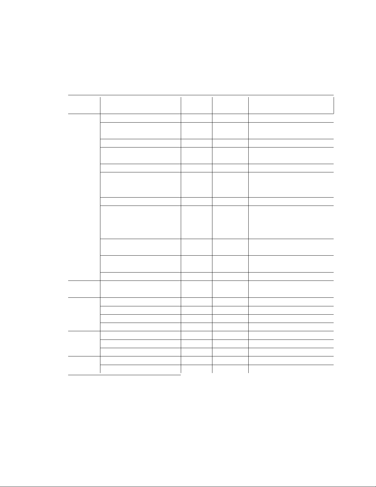
Figure 3.1: Scalar Types
Alignment AMD64
Type C sizeof (bytes) Architecture
_Bool
char 1 1 signed byte
signed char
unsigned char 1 1 unsigned byte
short 2 2 signed twobyte
signed short
unsigned short 2 2 unsigned twobyte
int 4 4 signed fourbyte
Integral signed int
enum
unsigned int 4 4 unsigned fourbyte
long 8 8 signed eightbyte
signed long
long long
signed long long
unsigned long 8 8 unsigned eightbyte
unsigned long long 8 8 unsigned eightbyte
__int128
signed __int128
unsigned __int128
Pointer any-type
any-type (*)()
Floating- float 4 4 single (IEEE-754)
point double 8 8 double (IEEE-754)
long double 16 16 80-bit extended (IEEE-754)
__float128
Decimal- _Decimal32 4 4 32bit BID (IEEE-754R)
floating-
_Decimal64 8 8 64bit BID (IEEE-754R)
point _Decimal128 16 16 128bit BID (IEEE-754R)
Packed __m64
__m128
†
This type is called bool in C++.
††
These types are optional.
†††
C++ and some implementations of C permit enums larger than an int. The underlying
type is bumped to an unsigned int, long int or unsigned long int, in that order.
†††
†
††
††
††
*
††
††
††
1 1 boolean
16 16 signed sixteenbyte
16 16 signed sixteenbyte
16 16 unsigned sixteenbyte
8 8 unsigned eightbyte
16 16 128-bit extended (IEEE-754)
8 8 MMX and 3DNow!
16 16 SSE and SSE-2
12
AMD64 ABI Draft 0.99 – December 7, 2007 – 4:39
Page 14

double requires 16 bytes of storage, only the first 10 bytes are significant. The
remaining six bytes are tail padding, and the contents of these bytes are undefined.
The __int128 type is stored in little-endian order in memory, i.e., the 64
low-order bits are stored at a a lower address than the 64 high-order bits.
A null pointer (for all types) has the value zero.
The type size_t is defined as unsigned long.
Booleans, when stored in a memory object, are stored as single byte objects the
value of which is always 0 (false) or 1 (true). When stored in integer registers
(except for passing as arguments), all 8 bytes of the register are significant; any
nonzero value is considered true.
Like the Intel386 architecture, the AMD64 architecture in general does not
require all data accesses to be properly aligned. Misaligned data accesses are
slower than aligned accesses but otherwise behave identically. The only exception
is that __m128 must always be aligned properly.
Aggregates and Unions
Structures and unions assume the alignment of their most strictly aligned component. Each member is assigned to the lowest available offset with the appropriate
alignment. The size of any object is always a multiple of the object‘s alignment.
An array uses the same alignment as its elements, except that a local or global
array variable of length at least 16 bytes or a C99 variable-length array variable
always has alignment of at least 16 bytes.
4
Structure and union objects can require padding to meet size and alignment
constraints. The contents of any padding is undefined.
Bit-Fields
C struct and union definitions may include bit-fields that define integral values of
a specified size.
The ABI does not permit bit-fields having the type __m64 or __m128. Programs using bit-fields of these types are not portable.
Bit-fields that are neither signed nor unsigned always have non-negative values. Although they may have type char, short, int, or long (which can have neg-
4
The alignment requirement allows the use of SSE instructions when operating on the array.
The compiler cannot in general calculate the size of a variable-length array (VLA), but it is expected that most VLAs will require at least 16 bytes, so it is logical to mandate that VLAs have at
least a 16-byte alignment.
13
AMD64 ABI Draft 0.99 – December 7, 2007 – 4:39
Page 15
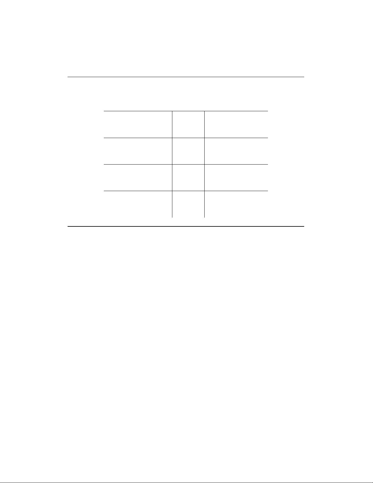
Figure 3.2: Bit-Field Ranges
Bit-field Type Width w Range
signed char −2
w−1
to 2
w−1
− 1
char 1 to 8 0 to 2w− 1
unsigned char 0 to 2w− 1
signed short −2
w−1
to 2
w−1
− 1
short 1 to 16 0 to 2w− 1
unsigned short 0 to 2w− 1
signed int −2
int
1 to 32 0 to 2w− 1
w−1
to 2
w−1
− 1
unsigned int 0 to 2w− 1
signed long −2
w−1
to 2
w−1
− 1
long 1 to 64 0 to 2w− 1
unsigned long 0 to 2w− 1
ative values), these bit-fields have the same range as a bit-field of the same size
with the corresponding unsigned type. Bit-fields obey the same size and alignment
rules as other structure and union members.
Also:
• bit-fields are allocated from right to left
• bit-fields must be contained in a storage unit appropriate for its declared
type
• bit-fields may share a storage unit with other struct / union members
Unnamed bit-fields’ types do not affect the alignment of a structure or union.
3.2 Function Calling Sequence
This section describes the standard function calling sequence, including stack
frame layout, register usage, parameter passing and so on.
The standard calling sequence requirements apply only to global functions.
Local functions that are not reachable from other compilation units may use dif-
14
AMD64 ABI Draft 0.99 – December 7, 2007 – 4:39
Page 16

ferent conventions. Nevertheless, it is recommended that all functions use the
standard calling sequence when possible.
3.2.1 Registers and the Stack Frame
The AMD64 architecture provides 16 general purpose 64-bit registers. In addition
the architecture provides 16 SSE registers, each 128 bits wide and 8 x87 floating
point registers, each 80 bits wide. Each of the x87 floating point registers may be
referred to in MMX /3DNow! mode as a 64-bit register. All of these registers are
global to all procedures active for a given thread.
This subsection discusses usage of each register. Registers %rbp, %rbx and
%r12 through %r15 “belong” to the calling function and the called function is
required to preserve their values. In other words, a called function must preserve
these registers’ values for its caller. Remaining registers “belong” to the called
function.5If a calling function wants to preserve such a register value across a
function call, it must save the value in its local stack frame.
The CPU shall be in x87 mode upon entry to a function. Therefore, every
function that uses the MMX registers is required to issue an emms or femms
instruction after using MMX registers, before returning or calling another function.
6
The direction flag DF in the %rFLAGS register must be clear (set to “forward”
direction) on function entry and return. Other user flags have no specified role in
the standard calling sequence and are not preserved across calls.
The control bits of the MXCSR register are callee-saved (preserved across
calls), while the status bits are caller-saved (not preserved). The x87 status word
register is caller-saved, whereas the x87 control word is callee-saved.
3.2.2 The Stack Frame
In addition to registers, each function has a frame on the run-time stack. This stack
grows downwards from high addresses. Figure 3.3 shows the stack organization.
The end of the input argument area shall be aligned on a 16 byte boundary.
In other words, the value (%rsp − 8) is always a multiple of 16 when control is
5
Note that in contrast to the Intel386 ABI, %rdi, and %rsi belong to the called function, not
the caller.
6
All x87 registers are caller-saved, so callees that make use of the MMX registers may use the
faster femms instruction.
15
AMD64 ABI Draft 0.99 – December 7, 2007 – 4:39
Page 17

Figure 3.3: Stack Frame with Base Pointer
Position Contents Frame
8n+16(%rbp) memory argument eightbyte n
. . . Previous
16(%rbp) memory argument eightbyte 0
8(%rbp) return address
0(%rbp) previous %rbp value
-8(%rbp) unspecified Current
. . .
0(%rsp) variable size
-128(%rsp) red zone
transferred to the function entry point. The stack pointer, %rsp, always points to
the end of the latest allocated stack frame.
7
The 128-byte area beyond the location pointed to by %rsp is considered to
be reserved and shall not be modified by signal or interrupt handlers.8Therefore,
functions may use this area for temporary data that is not needed across function
calls. In particular, leaf functions may use this area for their entire stack frame,
rather than adjusting the stack pointer in the prologue and epilogue. This area is
known as the red zone.
3.2.3 Parameter Passing
After the argument values have been computed, they are placed either in registers or pushed on the stack. The way how values are passed is described in the
following sections.
Definitions We first define a number of classes to classify arguments. The
classes are corresponding to AMD64 register classes and defined as:
7
The conventional use of %rbp as a frame pointer for the stack frame may be avoided by using
%rsp (the stack pointer) to index into the stack frame. This technique saves two instructions in
the prologue and epilogue and makes one additional general-purpose register (%rbp) available.
8
Locations within 128 bytes can be addressed using one-byte displacements.
16
AMD64 ABI Draft 0.99 – December 7, 2007 – 4:39
Page 18

INTEGER This class consists of integral types that fit into one of the general
purpose registers.
SSE The class consists of types that fits into a SSE register.
SSEUP The class consists of types that fit into a SSE register and can be passed
and returned in the most significant half of it.
X87, X87UP These classes consists of types that will be returned via the x87
FPU.
COMPLEX_X87 This class consists of types that will be returned via the x87
FPU.
NO_CLASS This class is used as initializer in the algorithms. It will be used for
padding and empty structures and unions.
MEMORY This class consists of types that will be passed and returned in mem-
ory via the stack.
Classification The size of each argument gets rounded up to eightbytes.
The basic types are assigned their natural classes:
• Arguments of types (signed and unsigned) _Bool, char, short, int,
long, long long, and pointers are in the INTEGER class.
• Arguments of types float, double, _Decimal32, _Decimal64 and
__m64 are in class SSE.
• Arguments of types __float128, _Decimal128 and __m128 are split
into two halves. The least significant ones belong to class SSE, the most
significant one to class SSEUP.
• The 64-bit mantissa of arguments of type long double belongs to class
X87, the 16-bit exponent plus 6 bytes of padding belongs to class X87UP.
• Arguments of type __int128 offer the same operations as INTEGERs,
yet they do not fit into one general purpose register but require two registers.
For classification purposes __int128 is treated as if it were implemented
as:
9
Therefore the stack will always be eightbyte aligned.
9
17
AMD64 ABI Draft 0.99 – December 7, 2007 – 4:39
Page 19

typedef struct {
long low, high;
} __int128;
with the exception that arguments of type __int128 that are stored in
memory must be aligned on a 16-byte boundary.
• Arguments of complex T where T is one of the types float or double
are treated as if they are implemented as:
struct complexT {
T real;
T imag;
};
• A variable of type complex long double is classified as type COM-
PLEX_X87.
The classification of aggregate (structures and arrays) and union types works
as follows:
1. If the size of an object is larger than two eightbytes, or it contains unaligned
fields, it has class MEMORY.
2. If a C++ object has either a non-trivial copy constructor or a non-trivial
destructor10it is passed by invisible reference (the object is replaced in the
parameter list by a pointer that has class INTEGER).
11
3. If the size of the aggregate exceeds a single eightbyte, each is classified
separately. Each eightbyte gets initialized to class NO_CLASS.
10
A de/constructor is trivial if it is an implicitly-declared default de/constructor and if:
• its class has no virtual functions and no virtual base classes, and
• all the direct base classes of its class have trivial de/constructors, and
• for all the nonstatic data members of its class that are of class type (or array thereof), each
such class has a trivial de/constructor.
11
An object with either a non-trivial copy constructor or a non-trivial destructor cannot be
passed by value because such objects must have well defined addresses. Similar issues apply
when returning an object from a function.
18
AMD64 ABI Draft 0.99 – December 7, 2007 – 4:39
Page 20

4. Each field of an object is classified recursively so that always two fields are
considered. The resulting class is calculated according to the classes of the
fields in the eightbyte:
(a) If both classes are equal, this is the resulting class.
(b) If one of the classes is NO_CLASS, the resulting class is the other
class.
(c) If one of the classes is MEMORY, the result is the MEMORY class.
(d) If one of the classes is INTEGER, the result is the INTEGER.
(e) If one of the classes is X87, X87UP, COMPLEX_X87 class, MEM-
ORY is used as class.
(f) Otherwise class SSE is used.
5. Then a post merger cleanup is done:
(a) If one of the classes is MEMORY, the whole argument is passed in
memory.
(b) If SSEUP is not preceeded by SSE, it is converted to SSE.
Passing Once arguments are classified, the registers get assigned (in left-to-right
order) for passing as follows:
1. If the class is MEMORY, pass the argument on the stack.
2. If the class is INTEGER, the next available register of the sequence %rdi,
%rsi, %rdx, %rcx, %r8 and %r9 is used12.
3. If the class is SSE, the next available SSE register is used, the registers are
taken in the order from %xmm0 to %xmm7.
4. If the class is SSEUP, the eightbyte is passed in the upper half of the last
used SSE register.
12
Note that %r11 is neither required to be preserved, nor is it used to pass arguments. Making
this register available as scratch register means that code in the PLT need not spill any registers
when computing the address to which control needs to be transferred. %rax is used to indicate the
number of SSE arguments passed to a function requiring a variable number of arguments. %r10
is used for passing a function’s static chain pointer.
19
AMD64 ABI Draft 0.99 – December 7, 2007 – 4:39
Page 21

5. If the class is X87, X87UP or COMPLEX_X87, it is passed in memory.
When a value of type _Bool is passed in a register or on the stack, the upper
63 bits of the eightbyte shall be zero.
If there are no registers available for any eightbyte of an argument, the whole
argument is passed on the stack. If registers have already been assigned for some
eightbytes of such an argument, the assignments get reverted.
Once registers are assigned, the arguments passed in memory are pushed on
the stack in reversed (right-to-left13) order.
For calls that may call functions that use varargs or stdargs (prototype-less
calls or calls to functions containing ellipsis (. . . ) in the declaration) %al14is used
as hidden argument to specify the number of SSE registers used. The contents of
%al do not need to match exactly the number of registers, but must be an upper
bound on the number of SSE registers used and is in the range 0–8 inclusive.
Returning of Values The returning of values is done according to the following
algorithm:
1. Classify the return type with the classification algorithm.
2. If the type has class MEMORY, then the caller provides space for the return
value and passes the address of this storage in %rdi as if it were the first
argument to the function. In effect, this address becomes a “hidden” first
argument.
On return %rax will contain the address that has been passed in by the
caller in %rdi.
3. If the class is INTEGER, the next available register of the sequence %rax,
%rdx is used.
4. If the class is SSE, the next available SSE register of the sequence %xmm0,
%xmm1 is used.
5. If the class is SSEUP, the eightbyte is passed in the upper half of the last
used SSE register.
13
Right-to-left order on the stack makes the handling of functions that take a variable number
of arguments simpler. The location of the first argument can always be computed statically, based
on the type of that argument. It would be difficult to compute the address of the first argument if
the arguments were pushed in left-to-right order.
14
Note that the rest of %rax is undefined, only the contents of %al is defined.
20
AMD64 ABI Draft 0.99 – December 7, 2007 – 4:39
Page 22

Figure 3.4: Register Usage
Preserved across
Register Usage function calls
%rax temporary register; with variable arguments
No
passes information about the number of SSE registers used; 1streturn register
%rbx callee-saved register; optionally used as base
Yes
pointer
%rcx used to pass 4thinteger argument to functions No
%rdx used to pass 3rdargument to functions; 2ndreturn
No
register
%rsp stack pointer Yes
%rbp callee-saved register; optionally used as frame
Yes
pointer
%rsi used to pass 2ndargument to functions No
%rdi used to pass 1stargument to functions No
%r8 used to pass 5thargument to functions No
%r9
%r10 temporary register, used for passing a function’s
used to pass 6thargument to functions No
No
static chain pointer
%r11 temporary register No
%r12-r15 callee-saved registers Yes
%xmm0–%xmm1 used to pass and return floating point arguments No
%xmm2–%xmm7
used to pass floating point arguments No
%xmm8–%xmm15 temporary registers No
%mmx0–%mmx7 temporary registers No
%st0,%st1 temporary registers; used to return long
No
double arguments
%st2–%st7 temporary registers No
%fs Reserved for system (as thread specific data reg-
No
ister)
mxcsr SSE2 control and status word partial
x87 SW x87 status word No
x87 CW x87 control word Yes
21
AMD64 ABI Draft 0.99 – December 7, 2007 – 4:39
Page 23

6. If the class is X87, the value is returned on the X87 stack in %st0 as 80-bit
x87 number.
7. If the class is X87UP, the value is returned together with the previous X87
value in %st0.
8. If the class is COMPLEX_X87, the real part of the value is returned in
%st0 and the imaginary part in %st1.
As an example of the register passing conventions, consider the declarations
and the function call shown in Figure 3.5. The corresponding register allocation
is given in Figure 3.6, the stack frame offset given shows the frame before calling
the function.
Figure 3.5: Parameter Passing Example
typedef struct {
int a, b;
double d;
} structparm;
structparm s;
int e, f, g, h, i, j, k;
long double ld;
double m, n;
extern void func (int e, int f,
structparm s, int g, int h,
long double ld, double m,
double n, int i, int j, int k);
func (e, f, s, g, h, ld, m, n, i, j, k);
22
AMD64 ABI Draft 0.99 – December 7, 2007 – 4:39
Page 24

Figure 3.6: Register Allocation Example
General Purpose Registers Floating Point Registers Stack Frame Offset
%rdi: e %xmm0: s.d 0: ld
%rsi: f %xmm1: m 16: j
%rdx: s.a,s.b %xmm2: n 24: k
%rcx: g
%r8: h
%r9: i
3.3 Operating System Interface
3.3.1 Exception Interface
As the AMD64 manuals describe, the processor changes mode to handle exceptions, which may be synchronous, floating-point/coprocessor or asynchronous.
Synchronous and floating-point/coprocessor exceptions, being caused by instruction execution, can be explicitly generated by a process. This section, therefore,
specifies those exception types with defined behavior. The AMD64 architecture
classifies exceptions as faults, traps, and aborts. See the Intel386 ABI for more
information about their differences.
Hardware Exception Types
The operating system defines the correspondence between hardware exceptions
and the signals specified by signal (BA_OS) as shown in table 3.1. Contrary
to the i386 architecture, the AMD64 does not define any instructions that generate
a bounds check fault in long mode.
3.3.2 Virtual Address Space
Although the AMD64 architecture uses 64-bit pointers, implementations are only
required to handle 48-bit addresses. Therefore, conforming processes may only
use addresses from 0x00000000 00000000 to 0x00007fff ffffffff15.
15
0x0000ffff ffffffff is not a canonical address and cannot be used.
23
AMD64 ABI Draft 0.99 – December 7, 2007 – 4:39
Page 25

Table 3.1: Hardware Exceptions and Signals
Number Exception name Signal
0 divide error fault SIGFPE
1 single step trap/fault SIGTRAP
2 non-maskable interrupt none
3 breakpoint trap SIGTRAP
4 overflow trap SIGSEGV
5 (reserved)
6 invalid opcode fault SIGILL
7 no coprocessor fault SIGFPE
8 double fault abort none
9 coprocessor overrun abort SIGSEGV
10 invalid TSS fault none
11 segment no present fault none
12 stack exception fault SIGSEGV
13
general protection fault/abort SIGSEGV
14 page fault SIGSEGV
15 (reserved)
16 coprocessor error fault SIGFPE
other (unspecified) SIGILL
Table 3.2: Floating-Point Exceptions
Code Reason
FPE_FLTDIV floating-point divide by zero
FPE_FLTOVF floating-point overflow
FPE_FLTUND floating-point underflow
FPE_FLTRES floating-point inexact result
FPE_FLTINV invalid floating-point operation
24
AMD64 ABI Draft 0.99 – December 7, 2007 – 4:39
Page 26

Processes begin with three logical segments, commonly called text, data, and
stack. Use of shared libraries add other segments and a process may dynamically
create segments.
3.3.3 Page Size
Systems are permitted to use any power-of-two page size between 4KB and 64KB,
inclusive.
3.3.4 Virtual Address Assignments
Conceptually processes have the full address space available. In practice, however, several factors limit the size of a process.
• The system reserves a configuration dependent amount of virtual space.
• The system reserves a configuration dependent amount of space per process.
• A process whose size exceeds the system’s available combined physical
memory and secondary storage cannot run. Although some physical memory must be present to run any process, the system can execute processes
that are bigger than physical memory, paging them to and from secondary
storage. Nonetheless, both physical memory and secondary storage are
shared resources. System load, which can vary from one program execution to the next, affects the available amount.
Programs that dereference null pointers are erroneous and a process should
not expect 0x0 to be a valid address.
Figure 3.7: Virtual Address Configuration
0xffffffffffffffff Reserved system area End of memory
. . .
. . .
0x80000000000 Dynamic segments
. . .
0 Process segments Beginning of memory
25
AMD64 ABI Draft 0.99 – December 7, 2007 – 4:39
Page 27

Although applications may control their memory assignments, the typical arrangement appears in figure 3.8.
Figure 3.8: Conventional Segment Arrangements
. . .
0x80000000000 Dynamic segments
Stack segment
. . .
. . .
Data segments
. . .
0x400000 Text segments
0 Unmapped
3.4 Process Initialization
3.4.1 Initial Stack and Register State
Special Registers
The AMD64 architecture defines floating point instructions. At process startup
the two floating point units, SSE2 and x87, both have all floating-point exception
status flags cleared. The status of the control words is as defined in tables 3.3 and
3.4.
26
AMD64 ABI Draft 0.99 – December 7, 2007 – 4:39
Page 28

Table 3.3: x87 Floating-Point Control Word
Field Value Note
RC 0 Round to nearest
PC 11 Double extended precision
PM 1 Precision masked
UM 1 Underflow masked
OM
1 Overflow masked
ZM 1 Zero divide masked
DM 1 De-normal operand masked
IM 1 Invalid operation masked
Table 3.4: MXCSR Status Bits
Field Value Note
FZ 0 Do not flush to zero
RC 0 Round to nearest
PM 1 Precision masked
UM 1 Underflow masked
OM 1 Overflow masked
ZM 1 Zero divide masked
DM 1 De-normal operand masked
IM 1 Invalid operation masked
DAZ
0 De-normals are not zero
The rFLAGS register contains the system flags, such as the direction flag and
the carry flag. The low 16 bits (FLAGS portion) of rFLAGS are accessible by
application software. The state of them at process initialization is shown in table
3.5.
27
AMD64 ABI Draft 0.99 – December 7, 2007 – 4:39
Page 29

Table 3.5: rFLAGS Bits
Field Value Note
DF 0 Direction forward
CF 0 No carry
PF 0 Even parity
AF 0 No auxiliary carry
ZF
0 No zero result
SF 0 Unsigned result
OF 0 No overflow occurred
Stack State
This section describes the machine state that exec (BA_OS) creates for new
processes. Various language implementations transform this initial program state
to the state required by the language standard.
For example, a C program begins executing at a function named main declared as:
extern int main ( int argc , char*argv[ ] , char*envp[ ] );
where
argc is a non-negative argument count
argv is an array of argument strings, with argv[argc] == 0
envp is an array of environment strings, terminated by a null pointer.
When main() returns its value is passed to exit() and if that has been
over-ridden and returns, _exit() (which must be immune to user interposition).
The initial state of the process stack, i.e. when _start is called is shown in
figure 3.9.
28
AMD64 ABI Draft 0.99 – December 7, 2007 – 4:39
Page 30

Figure 3.9: Initial Process Stack
Purpose Start Address Length
Unspecified High Addresses
Information block, including argu-
varies
ment strings, environment strings,
auxiliary information ...
Unspecified
Null auxiliary vector entry 1 eightbyte
Auxiliary vector entries ... 2 eightbytes each
0 eightbyte
Environment pointers ... 1 eightbyte each
0 8+8*argc+%rsp eightbyte
Argument pointers 8+%rsp argc eightbytes
Argument count %rsp eightbyte
Undefined Low Addresses
Argument strings, environment strings, and the auxiliary information appear
in no specific order within the information block and they need not be compactly
allocated.
Only the registers listed below have specified values at process entry:
%rbp The content of this register is unspecified at process initialization time,
but the user code should mark the deepest stack frame by setting the frame
pointer to zero.
%rsp The stack pointer holds the address of the byte with lowest address which
is part of the stack. It is guaranteed to be 16-byte aligned at process entry.
%rdx a function pointer that the application should register with atexit (BA_OS).
It is unspecified whether the data and stack segments are initially mapped with
execute permissions or not. Applications which need to execute code on the stack
or data segments should take proper precautions, e.g., by calling mprotect().
29
AMD64 ABI Draft 0.99 – December 7, 2007 – 4:39
Page 31

3.4.2 Thread State
New threads inherit the floating-point state of the parent thread and the state is
private to the thread thereafter.
3.4.3 Auxiliary Vector
The auxiliary vector is an array of the following structures (ref. figure 3.10),
interpreted according to the a_type member.
Figure 3.10: auxv_t Type Definition
typedef struct
{
int a_type;
union {
long a_val;
void*a_ptr;
void (*a_fnc)();
} a_un;
} auxv_t;
The AMD64 ABI uses the auxiliary vector types defined in figure 3.11.
30
AMD64 ABI Draft 0.99 – December 7, 2007 – 4:39
Page 32

Figure 3.11: Auxiliary Vector Types
Name Value a_un
AT_NULL 0 ignored
AT_IGNORE 1 ignored
AT_EXECFD 2 a_val
AT_PHDR 3 a_ptr
AT_PHENT 4 a_val
AT_PHNUM 5 a_val
AT_PAGESZ 6 a_val
AT_BASE
7 a_ptr
AT_FLAGS 8 a_val
AT_ENTRY 9 a_ptr
AT_NOTELF 10 a_val
AT_UID 11 a_val
AT_EUID 12 a_val
AT_GID 13 a_val
AT_EGID 14 a_val
AT_NULL The auxiliary vector has no fixed length; instead its last entry’s a_type
member has this value.
AT_IGNORE This type indicates the entry has no meaning. The corresponding
value of a_un is undefined.
AT_EXECFD At process creation the system may pass control to an interpreter
program. When this happens, the system places either an entry of type
AT_EXECFD or one of type AT_PHDR in the auxiliary vector. The entry
for type AT_EXECFD uses the a_val member to contain a file descriptor
open to read the application program’s object file.
AT_PHDR The system may create the memory image of the application program
before passing control to the interpreter program. When this happens, the
a_ptr member of the AT_PHDR entry tells the interpreter where to find
the program header table in the memory image.
31
AMD64 ABI Draft 0.99 – December 7, 2007 – 4:39
Page 33

AT_PHENT The a_val member of this entry holds the size, in bytes, of one
entry in the program header table to which the AT_PHDR entry points.
AT_PHNUM The a_val member of this entry holds the number of entries in
the program header table to which the AT_PHDR entry points.
AT_PAGESZ If present, this entry’s a_val member gives the system page size,
in bytes.
AT_BASE The a_ptr member of this entry holds the base address at which the
interpreter program was loaded into memory. See “Program Header” in the
System V ABI for more information about the base address.
AT_FLAGS If present, the a_val member of this entry holds one-bit flags. Bits
with undefined semantics are set to zero.
AT_ENTRY The a_ptr member of this entry holds the entry point of the appli-
cation program to which the interpreter program should transfer control.
AT_NOTELF The a_val member of this entry is non-zero if the program is in
another format than ELF.
AT_UID The a_val member of this entry holds the real user id of the process.
AT_EUID The a_val member of this entry holds the effective user id of the
process.
AT_GID The a_val member of this entry holds the real group id of the process.
AT_EGID The a_val member of this entry holds the effective group id of the
process.
3.5 Coding Examples
This section discusses example code sequences for fundamental operations such
as calling functions, accessing static objects, and transferring control from one
part of a program to another. Unlike previous material, this material is not normative.
32
AMD64 ABI Draft 0.99 – December 7, 2007 – 4:39
Page 34

3.5.1 Architectural Constraints
The AMD64 architecture usually does not allow an instruction to encode arbitrary
64-bit constants as immediate operand. Most instructions accept 32-bit immediates that are sign extended to the 64-bit ones. Additionally the 32-bit operations
with register destinations implicitly perform zero extension making loads of 64-bit
immediates with upper half set to 0 even cheaper.
Additionally the branch instructions accept 32-bit immediate operands that are
sign extended and used to adjust the instruction pointer. Similarly an instruction
pointer relative addressing mode exists for data accesses with equivalent limitations.
In order to improve performance and reduce code size, it is desirable to use
different code models depending on the requirements.
Code models define constraints for symbolic values that allow the compiler to
generate better code. Basically code models differ in addressing (absolute versus
position independent), code size, data size and address range. We define only a
small number of code models that are of general interest:
Small code model The virtual address of code executed is known at link time.
Additionally all symbols are known to be located in the virtual addresses in
the range from 0 to 231− 224− 1 or from 0x00000000 to 0x7ef f f fff16.
This allows the compiler to encode symbolic references with offsets in the
range from −(231) to 224or from 0x80000000 to 0x01000000 directly in the
sign extended immediate operands, with offsets in the range from 0 to 231−
224or from 0x00000000 to 0x7f 000000 in the zero extended immediate
operands and use instruction pointer relative addressing for the symbols
with offsets in the range −(224) to 224or 0xf f 000000 to 0x01000000.
This is the fastest code model and we expect it to be suitable for the vast
majority of programs.
Kernel code model The kernel of an operating system is usually rather small but
runs in the negative half of the address space. So we define all symbols to
be in the range from 264− 231to 264− 224or from 0xf f f fff f f 80000000
to 0xf f f fff f f ff000000.
16
The number 24 is chosen arbitrarily. It allows for all memory of objects of size up to 2
or 16M bytes to be addressed directly because the base address of such objects is constrained to
be less than 231− 224or 0x7f 000000. Without such constraint only the base address would be
accessible directly, but not any offsetted variant of it.
24
33
AMD64 ABI Draft 0.99 – December 7, 2007 – 4:39
Page 35

This code model has advantages similar to those of the small model, but
allows encoding of zero extended symbolic references only for offsets from
231to 231+ 224or from 0x80000000 to 0x81000000. The range offsets
for sign extended reference changes to 0 to 231+ 224or 0x00000000 to
0x81000000.
Medium code model In the medium model, the data section is split into two
parts — the data section still limited in the same way as in the small code
model and the large data section having no limits except for available addressing space. The program layout must be set in a way so that large data
sections (.ldata, .lrodata, .lbss) come after the text and data sections.
This model requires the compiler to use movabs instructions to access
large static data and to load addresses into registers, but keeps the advantages of the small code model for manipulation of addresses in the small
data and text sections (specially needed for branches).
By default only data larger than 65535 bytes will be placed in the large data
section.
Large code model The large code model makes no assumptions about addresses
and sizes of sections.
The compiler is required to use the movabs instruction, as in the medium
code model, even for dealing with addresses inside the text section. Additionally, indirect branches are needed when branching to addresses whose
offset from the current instruction pointer is unknown.
It is possible to avoid the limitation on the text section in the small and
medium models by breaking up the program into multiple shared libraries,
so this model is strictly only required if the text of a single function becomes
larger than what the medium model allows.
Small position independent code model (PIC) Unlike the previous models, the
virtual addresses of instructions and data are not known until dynamic link
time. So all addresses have to be relative to the instruction pointer.
Additionally the maximum distance between a symbol and the end of an
instruction is limited to 231−224−1 or 0x7ef fff f f , allowing the compiler
to use instruction pointer relative branches and addressing modes supported
34
AMD64 ABI Draft 0.99 – December 7, 2007 – 4:39
Page 36

by the hardware for every symbol with an offset in the range −(224) to 2
24
or 0xf f 000000 to 0x01000000.
Medium position independent code model (PIC) This model is like the previ-
ous model, but similarly to the medium static model adds large data sections
at the end of object files.
In the medium PIC model, the instruction pointer relative addressing can
not be used directly for accessing large static data, since the offset can exceed the limitations on the size of the displacement field in the instruction.
Instead an unwind sequence consisting of movabs, lea and add needs to
be used.
Large position independent code model (PIC) This model is like the previous
model, but makes no assumptions about the distance of symbols.
The large PIC model implies the same limitation as the medium PIC model
regarding addressing of static data. Additionally, references to the global
offset table and to the procedure linkage table and branch destinations need
to be calculated in a similar way. Further the size of the text segment is
allowed to be up to 16EB in size, hence similar restrictions apply to all
address references into the text segments, including branches.
3.5.2 Conventions
In this document some special assembler symbols are used in the coding examples
and discussion. They are:
• name@GOT: specifies the offset to the GOT entry for the symbol name
from the base of the GOT.
• name@GOTPLT: specifies the offset to the GOT entry for the symbol name
from the base of the GOT, implying that there is a corresponding PLT entry.
• name@GOTOFF: specifies the offset to the location of the symbol name
from the base of the GOT.
• name@GOTPCREL: specifies the offset to the GOT entry for the symbol
name from the current code location.
• name@PLT: specifies the offset to the PLT entry of symbol name from the
current code location.
35
AMD64 ABI Draft 0.99 – December 7, 2007 – 4:39
Page 37

• name@PLTOFF: specifies the offset to the PLT entry of symbol name from
the base of the GOT.
• _GLOBAL_OFFSET_TABLE_: specifies the offset to the base of the GOT
from the current code location.
3.5.3 Position-Independent Function Prologue
In the small code model all addresses (including GOT entries) are accessible via
the IP-relative addressing provided by the AMD64 architecture. Hence there is no
need for an explicit GOT pointer and therefore no function prologue for setting it
up is necessary.
In the medium and large code models a register has to be allocated to hold
the address of the GOT in position-independent objects, because the AMD64 ISA
does not support an immediate displacement larger than 32 bits.
As %r15 is preserved across function calls, it is initialized in the function
prolog to hold the GOT address17for non-leaf functions which call other functions
through the PLT. Other functions are free to use any other register. Throughout
this document, %r15 will be used in examples.
Figure 3.12: Position-Independent Function Prolog Code
medium model:
leaq _GLOBAL_OFFSET_TABLE_(%rip),%r15 # GOTPC32 reloc
large model:
pushq %r15 # save %r15
leaq 1f(%rip),%r11 # absolute %rip
1: movabs $_GLOBAL_OFFSET_TABLE_,%r15 # offset to the GOT (R_X86_64_GOTPC64)
leaq (%r11,%r15),%r15 # absolute address of the GOT
For the medium model the GOT pointer is directly loaded, for the large model
the absolute value of %rip is added to the relative offset to the base of the GOT
17
If, at code generation-time, it is determined that either no other functions are called (leaf
functions), the called functions addresses can be resolved and are within 2GB, or no global data
objects are referred to, it is not necessary to store the GOT address in %r15 and the prolog code
that initializes it may be omitted.
36
AMD64 ABI Draft 0.99 – December 7, 2007 – 4:39
Page 38

in order to obtain its absolute address (see figure 3.12).
3.5.4 Data Objects
This section describes only objects with static storage. Stack-resident objects are
excluded since programs always compute their virtual address relative to the stack
or frame pointers.
Because only the movabs instruction uses 64-bit addresses directly, depending on the code model either %rip-relative addressing or building addresses in
registers and accessing the memory through the register has to be used.
For absolute addresses %rip-relative encoding can be used in the small model.
In the medium model the movabs instruction has to be used for accessing addresses.
Position-independent code cannot contain absolute address. To access a global
symbol the address of the symbol has to be loaded from the Global Offset Table.
The address of the entry in the GOT can be obtained with a %rip-relative instruction in the small model.
37
AMD64 ABI Draft 0.99 – December 7, 2007 – 4:39
Page 39

Small models
Figure 3.13: Absolute Load and Store (Small Model)
extern int src[65536]; .extern src
extern int dst[65536]; .extern dst
extern int*ptr; .extern ptr
static int lsrc[65536]; .local lsrc
.comm lsrc,262144,4
static int ldst[65536]; .local ldst
.comm ldst,262144,4
static int*lptr; .local lptr
.comm lptr,8,8
.text
dst[0] = src[0]; movl src(%rip), %eax
movl %eax, dst(%rip)
ptr = dst[0]; movq $dst, ptr(%rip)
ptr = src[0]; movq ptr(%rip),%rax
*
movl src(%rip),%edx
movl %edx, (%rax)
ldst[0] = lsrc[0]; movl lsrc(%rip), %eax
movl %eax, ldst(%rip)
lptr = ldst; movq $dst, lptr(%rip)
lptr = lsrc[0]; movq lptr(%rip),%rax
*
movl lsrc(%rip),%edx
movl %edx, (%rax)
38
AMD64 ABI Draft 0.99 – December 7, 2007 – 4:39
Page 40

Figure 3.14: Position-Independent Load and Store (Small PIC Model)
extern int src[65536]; .extern src
extern int dst[65536]; .extern dst
extern int*ptr; .extern ptr
static int lsrc[65536]; .local lsrc
.comm lsrc,262144,4
static int ldst[65536]; .local ldst
.comm ldst,262144,4
static int*lptr; .local lptr
.comm lptr,8,8
.text
dst[0] = src[0]; movq src@GOTPCREL(%rip), %rax
movl (%rax), %edx
movq dst@GOTPCREL(%rip), %rax
movl %edx, (%rax)
ptr = dst; movq ptr@GOTPCREL(%rip), %rax
movq dst@GOTPCREL(%rip), %rdx
movq %rdx, (%rax)
ptr = src[0]; movq ptr@GOTPCREL(%rip),%rax
*
movq (%rax), %rdx
movq src@GOTPCREL(%rip), %rax
movl (%rax), %eax
movl %eax, (%rdx)
ldst[0] = lsrc[0]; movl lsrc(%rip), %eax
movl %eax, ldst(%rip)
lptr = ldst; lea ldst(%rip),%rdx
movq %rdx, lptr(%rip)
lptr = lsrc[0]; movq lptr(%rip),%rax
*
movl lsrc(%rip),%edx
movl %edx, (%rax)
39
AMD64 ABI Draft 0.99 – December 7, 2007 – 4:39
Page 41

Medium models
Figure 3.15: Absolute Load and Store (Medium Model)
extern int src[65536]; .extern src
extern int dst[65536]; .extern dst
extern int*ptr; .extern ptr
static int lsrc[65536]; .local lsrc
.comm lsrc,262144,4
static int ldst[65536]; .local ldst
.comm ldst,262144,4
static int*lptr; .local lptr
.comm lptr,8,8
.text
dst[0] = src[0]; movabsl src, %eax
movabsl %eax, dst
ptr = dst; movabsq $dst,%rdx
movq %rdx, ptr
18
ptr = src[0]; movq ptr(%rip),%rdx
*
movabsl src,%eax
movl %eax, (%rdx)
ldst[0] = lsrc[0]; movabsl lsrc, %eax
movabsl %eax, ldst
lptr = ldst; movabsq $ldst,%rdx
movabsq %rdx, lptr
lptr = lsrc[0]; movq lptr(%rip),%rdx
*
movabsl lsrc,%eax
movl %eax, (%rdx)
40
AMD64 ABI Draft 0.99 – December 7, 2007 – 4:39
Page 42

Figure 3.16: Position-Independent Load and Store (Medium PIC Model)
extern int src[65536]; .extern src
extern int dst[65536]; .extern dst
extern int*ptr; .extern ptr
static int lsrc[65536]; .local lsrc
.comm lsrc,262144,4
static int ldst[65536]; .local ldst
.comm ldst,262144,4
static int*lptr; .local lptr
.comm lptr,8,8
.text
dst[0] = src[0]; movq src@GOTPCREL(%rip), %rax
movl (%rax), %edx
movq dst@GOTPCREL(%rip), %rax
movl %edx, (%rax)
ptr = dst; movq ptr@GOTPCREL(%rip), %rax
movq dst@GOTPCREL(%rip), %rdx
movq %rdx, (%rax)
ptr = src[0]; movq ptr@GOTPCREL(%rip),%rax
*
movq (%rax), %rdx
movq src@GOTPCREL(%rip), %rax
movl (%rax), %eax
movl %eax, (%rdx)
41
AMD64 ABI Draft 0.99 – December 7, 2007 – 4:39
Page 43

Figure 3.17: Position-Independent Load and Store (Medium PIC Model), continued
ldst[0] = lsrc[0]; movabsq lsrc@GOTOFF64, %rax
movl (%rax,%r15), %eax
movabsq ldst@GOTOFF64, %rdx
movl %eax, (%rdx,%r15)
lptr = ldst; movabsq ldst@GOTOFF64, %rax
addq %r15, %rax
movq %rax, lptr(%rip)
lptr = lsrc[0]; movabsq lsrc@GOTOFF64, %rax
*
movl (%rax,%r15),%eax
movq lptr(%rip),%rdx
movl %eax, (%rdx)
Large Models
Again, in order to access data at any position in the 64-bit addressing space, it is
necessary to calculate the address explicitly19, not unlike the medium code model.
19
If, at code generation-time, it is determined that a referred to global data object address is
resolved within 2GB, the %rip-relative addressing mode can be used instead. See example
in figure 3.19.
42
AMD64 ABI Draft 0.99 – December 7, 2007 – 4:39
Page 44
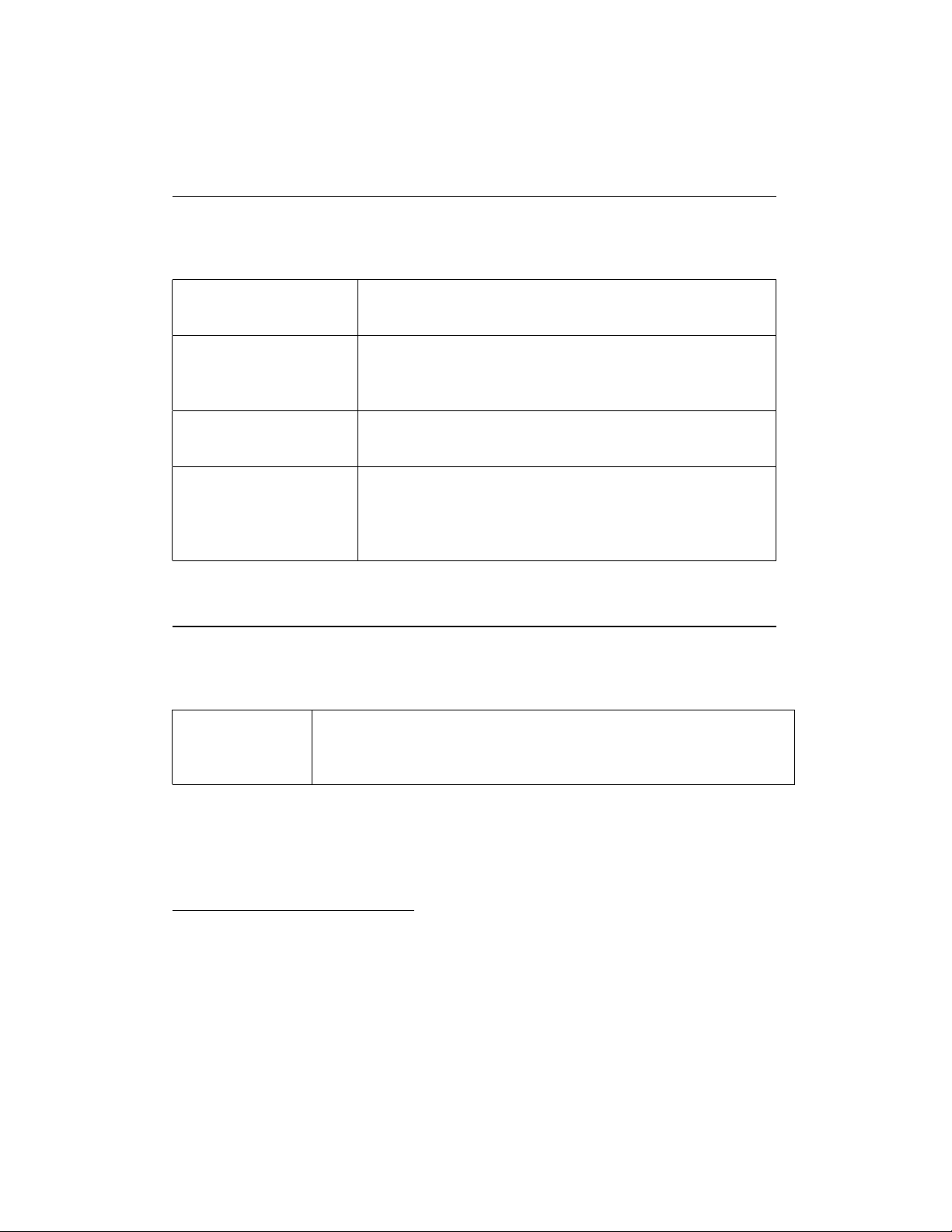
Figure 3.18: Absolute Global Data Load and Store
static int src; Lsrc: .long
static int dst; Ldst: .long
extern int*ptr; .extern ptr
dst = src; movabs $Lsrc,%rax ; R_X86_64_64
movabs $Ldst,%rdx ; R_X86_64_64
movl (%rax),%ecx
movl %ecx,(%rdx)
ptr = &dst; movabs $ptr,%rax ; R_X86_64_64
movabs $Ldst,%rdx ; R_X86_64_64
movq %rdx,(%rax)
ptr = src; movabs $Lsrc,%rax ; R_X86_64_64
*
movabs $ptr,%rdx ; R_X86_64_64
movl (%rax),%ecx
movq (%rdx),%rdx
movl %ecx,(%rdx)
Figure 3.19: Faster Absolute Global Data Load and Store
ptr = src; movabs $ptr,%rdx ; R_X86_64_64
*
movl Lsrc(%rip),%ecx
movq (%rdx),%rdx
movl %ecx,(%rdx)
For position-independent code access to both static and external global data
assumes that the GOT address is stored in a dedicated register. In these examples
we assume it is in %r1520(see Function Prologue):
20
If, at code generation-time, it is determined that a referred to global data object address is
resolved within 2GB, the %rip-relative addressing mode can be used instead. See example
in figure 3.21.
43
AMD64 ABI Draft 0.99 – December 7, 2007 – 4:39
Page 45
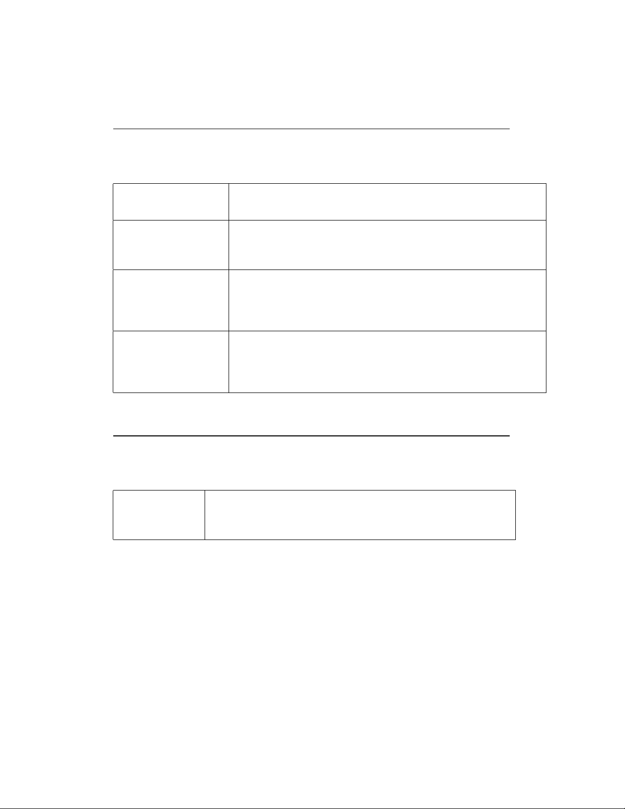
Figure 3.20: Position-Independent Global Data Load and Store
static int src; Lsrc: .long
static int dst; Ldst: .long
extern int*ptr; .extern ptr
dst = src; movabs $Lsrc@GOTOFF,%rax ; R_X86_64_GOTOFF64
movabs $Ldst@GOTOFF,%rdx ; R_X86_64_GOTOFF64
movl (%rax,%r15),%ecx
movl %ecx,(%rdx,%r15)
ptr = &dst; movabs $ptr@GOT,%rax ; R_X86_64_GOT64
movabs $Ldst@GOTOFF,%rdx ; R_X86_64_GOTOFF64
movq (%rax,%r15),%rax
leaq (%rdx,%r15),%rcx
movq %rcx,(%rax)
ptr = src; movabs $Lsrc@GOTOFF,%rax ; R_X86_64_GOTOFF64
*
movabs $ptr@GOT,%rdx ; R_X86_64_GOT64
movl (%rax,%r15),%ecx
movq (%rdx,%r15),%rdx
movl %ecx,(%rdx)
Figure 3.21: Faster Position-Independent Global Data Load and Store
ptr = src; movabs $ptr@GOT,%rdx ; R_X86_64_GOT64
*
movl Lsrc(%rip),%ecx
movq (%rdx,%r15),%rdx
movl %ecx,(%rdx)
44
AMD64 ABI Draft 0.99 – December 7, 2007 – 4:39
Page 46

3.5.5 Function Calls
Small and Medium Models
Figure 3.22: Position-Independent Direct Function Call (Small and Medium
Model)
extern void function (); .globl function
function (); call function@PLT
Figure 3.23: Position-Independent Indirect Function Call
extern void (*ptr) (); .globl ptr, name
extern void name ();
ptr = name; movq ptr@GOTPCREL(%rip), %rax
movq name@GOTPCREL(%rip), %rdx
movq %rdx, (%rax)
(*ptr)(); movq ptr@GOTPCREL(%rip), %rax
call*(%rax)
Large models
It cannot be assumed that a function is within 2GB in general. Therefore, it is
necessary to explicitly calculate the desired address reaching the whole 64-bit
address space.
45
AMD64 ABI Draft 0.99 – December 7, 2007 – 4:39
Page 47
Figure 3.24: Absolute Direct and Indirect Function Call
static void (*ptr) (void); Lptr: .quad
extern void foo (void); .globl foo
static void bar (void); Lbar: ...
foo (); movabs $foo,%r11 ; R_X86_64_64
call
bar (); movabs $Lbar,%r11 ; R_X86_64_64
call
ptr = foo; movabs $Lptr,%rax ; R_X86_64_64
movabs $foo,%r11 ; R_X86_64_64
movq %r11,(%rax)
ptr = bar; movabs $Lbar,%r11 ; R_X86_64_64
movq %r11,(%rax)
(*ptr) (); movabs $Lptr,%r11 ; R_X86_64_64
call
%r11
*
%r11
*
(%r11)
*
And in the case of position-independent objects21:
Figure 3.25: Position-Independent Direct and Indirect Function Call
static void (*ptr) (void); Lptr: .quad
extern void foo (void); .globl foo
static void bar (void); Lbar: ...
foo (); movabs $foo@GOT,%r11 ; R_x86_64_GOTPLT64
call
bar (); movabs $Lbar@GOTOFF,%r11 ; R_X86_64_GOTOFF64
leaq (%r11,%r15),%r11
call
ptr = foo; movabs $Lptr@GOTOFF,%rax ; R_X86_64_GOTOFF64
movabs $foo@PLTOFF,%r11 ; R_X86_64_PLTOFF64
leaq (%r11,%r15),%r11
movq %r11,(%rax,%r15)
ptr = bar; movabs $Lbar@GOTOFF,%r11 ; R_X86_64_GOTOFF64
leaq (%r11,%r15),%r11
movq %r11,(%rax,%r15)
(*ptr) (); movabs $Lptr@GOTOFF,%r11 ; R_X86_64_GOTOFF64
call
(%r11,%r15)
*
%r11
*
(%r11,%r15)
*
21
See subsection “Implementation advice” for some optimizations.
46
AMD64 ABI Draft 0.99 – December 7, 2007 – 4:39
Page 48
Implementation advice
If, at code generation-time, certain conditions are determined, it’s possible to
generate faster or smaller code sequences as the large model normally requires.
When:
(absolute) target of function call is within 2GB , a direct call or %rip-relative
addressing might be used:
bar (); call Lbar
ptr = bar; movabs $Lptr,%rax ; R_X86_64_64
leaq $Lbar(%rip),%r11
movq %r11,(%rax)
(PIC) the base of GOT is within 2GB an indirect call to the GOT entry might
be implemented like so:
foo (); call
(foo@GOT) ; R_X86_64_GOTPCREL
*
(PIC) the base of PLT is within 2GB , the PLT entry may be referred to rela-
tively to %rip:
ptr = foo; movabs $Lptr@GOTOFF,%rax ; R_X86_64_GOTOFF64
leaq $foo@PLT(%rip),%r11 ; R_X86_64_PLT32
movq %r11,(%rax,%r15)
(PIC) target of function call is within 2GB and is either not global or bound lo-
cally, a direct call to the symbol may be used or it may be referred to relatively to %rip:
bar (); call Lbar
ptr = bar; movabs $Lptr@GOTOFF,%rax ; R_X86_64_GOTOFF64
leaq $Lbar(%rip),%r11
movq %r11,(%rax,%r15)
3.5.6 Branching
Small and Medium Models
As all labels are within 2GB no special care has to be taken when implementing
branches. The full AMD64 ISA is usable.
Large Models
Because functions can be theoretically up to 16EB long, the maximum 32-bit
displacement of conditional and unconditional branches in the AMD64 ISA are
47
AMD64 ABI Draft 0.99 – December 7, 2007 – 4:39
Page 49

not enough to address the branch target. Therefore, a branch target address is
calculated explicitly22. For absolute objects:
Figure 3.26: Absolute Branching Code
if (!a) testl %eax,%eax
{ jnz 1f
movabs $2f,%r11 ; R_X86_64_64
jmpq
... 1: ...
} 2:
goto Label; movabs $Label,%r11 ; R_X86_64_64
jmpq
... ...
Label: Label:
%r11
*
%r11
*
Figure 3.27: Implicit Calculation of Target Address
if (!a) testl %eax,%eax
{ jz 2f
... 1: ...
} 2:
goto Label; jmp Label
... ...
Label: Label:
For position-independent objects:
22
If, at code generation-time, it is determined that the target addresses are within 2GB, alterna-
tively, branch target addresses may be calculated implicitly (see figure 3.27)
48
AMD64 ABI Draft 0.99 – December 7, 2007 – 4:39
Page 50

Figure 3.28: Position-Independent Branching Code
if (!a) testl %eax,%eax
{ jnz 1f
movabs $2f@GOTOFF,%r11 ; R_X86_64_GOTOFF64
leaq (%r11,%r15),%r11
jmpq
1: ...
... 2:
}
goto Label; movabs $Label@GOTOFF,%r11 ; R_X86_64_GOTOFF64
leaq (%r11,%r15),%r11
jmpq
...
... Label:
Label:
%r11
*
%r11
*
For absolute objects, the implementation of the switch statement is:
Figure 3.29: Absolute Switch Code
switch (a) cmpl $0,%eax
{ jl .Ldefault
cmpl $2,%eax
jg .Ldefault
movabs $.Ltable,%r11 ; R_X86_64_64
jmpq
.section .lrodata,"aLM",@progbits,8
.align 8
.Ltable: .quad .Lcase0 ; R_X86_64_64
.quad .Ldefault ; R_X86_64_64
.quad .Lcase2 ; R_X86_64_64
.previous
default: .Ldefault:
... ...
case 0: .Lcase0:
... ...
case 2: .Lcase2:
... ...
}
(%r11,%eax,8)
*
When building position-independent objects, the switch statement imple-
mentation changes to:
49
AMD64 ABI Draft 0.99 – December 7, 2007 – 4:39
Page 51

Figure 3.30: Position-Independent Switch Code
switch (a) cmpl $0,%eax
{ jl .Ldefault
cmpl $2,%eax
jg .Ldefault
movabs $.Ltable@GOTOFF,%r11 ; R_X86_64_GOTOFF64
leaq (%r11,%r15),%r11
movq
leaq (%r11,%r15),%r11
jmpq
.section .lrodata,"aLM",@progbits,8
.align 8
.Ltable: .quad .Lcase0@GOTOFF ; R_X86_64_GOTOFF64
default: .Ldefault:
... ...
case 0: .Lcase0:
... ...
case 2: .Lcase2:
... ...
}
(%r11,%eax,8),%r11
*
%r11
*
.quad .Ldefault@GOTOFF ; R_X86_64_GOTOFF64
.quad .Lcase2@GOTOFF ; R_X86_64_GOTOFF64
.previous
23
3.5.7 Variable Argument Lists
Some otherwise portable C programs depend on the argument passing scheme,
implicitly assuming that all arguments are passed on the stack, and arguments
appear in increasing order on the stack. Programs that make these assumptions
never have been portable, but they have worked on many implementations. However, they do not work on the AMD64 architecture because some arguments are
passed in registers. Portable C programs must use the header file <stdarg.h>
in order to handle variable argument lists.
When a function taking variable-arguments is called, %rax must be set to the
total number of floating point parameters passed to the function in SSE registers.
23
The jump-table is emitted in a different section so as to occupy cache lines without instruction
bytes, thus avoiding exclusive cache subsystems to thrash.
24
This implies that the only legal values for %rax when calling a function with variable-
50
AMD64 ABI Draft 0.99 – December 7, 2007 – 4:39
24
Page 52

Figure 3.31: Parameter Passing Example with Variable-Argument List
int a, b;
long double ld;
double m, n;
extern void func (int a, double m,...);
func (a, m, b, ld, n);
Figure 3.32: Register Allocation Example for Variable-Argument List
General Purpose Registers Floating Point Registers Stack Frame Offset
%rdi: a %xmm0: m 0: ld
%rsi: b
%xmm1: n
%rax: 2
The Register Save Area
The prologue of a function taking a variable argument list and known to call the
macro va_start is expected to save the argument registers to the register save
area. Each argument register has a fixed offset in the register save area as defined
in the figure 3.33.
Only registers that might be used to pass arguments need to be saved. Other
registers are not accessed and can be used for other purposes. If a function is
known to never accept arguments passed in registers25, the register save area may
be omitted entirely.
The prologue should use %rax to avoid unnecessarily saving XMM registers.
This is especially important for integer only programs to prevent the initialization
of the XMM unit.
argument lists are 0 to 8 (inclusive).
25
This fact may be determined either by exploring types used by the va_arg macro, or by the
fact that the named arguments already are exhausted the argument registers entirely.
51
AMD64 ABI Draft 0.99 – December 7, 2007 – 4:39
Page 53
Figure 3.33: Register Save Area
Register Offset
%rdi 0
%rsi 8
%rdx 16
%rcx 24
%r8 32
%r9 40
%xmm0 48
%xmm1
64
. . .
%xmm15 288
The va_list Type
The va_list type is an array containing a single element of one structure containing the necessary information to implement the va_arg macro. The C definition of va_list type is given in figure 3.34.
Figure 3.34: va_list Type Declaration
typedef struct {
unsigned int gp_offset;
unsigned int fp_offset;
void*overflow_arg_area;
void*reg_save_area;
} va_list[1];
The va_start Macro
The va_start macro initializes the structure as follows:
reg_save_area The element points to the start of the register save area.
52
AMD64 ABI Draft 0.99 – December 7, 2007 – 4:39
Page 54

overflow_arg_area This pointer is used to fetch arguments passed on the stack.
It is initialized with the address of the first argument passed on the stack, if
any, and then always updated to point to the start of the next argument on
the stack.
gp_offset The element holds the offset in bytes from reg_save_area to the
place where the next available general purpose argument register is saved.
In case all argument registers have been exhausted, it is set to the value 48
(6 ∗ 8).
fp_offset The element holds the offset in bytes from reg_save_area to the
place where the next available floating point argument register is saved. In
case all argument registers have been exhausted, it is set to the value 304
(6 ∗ 8 + 16 ∗ 16).
The va_arg Macro
The algorithm for the generic va_arg(l, type) implementation is defined as
follows:
1. Determine whether type may be passed in the registers. If not go to step
7.
2. Compute num_gp to hold the number of general purpose registers needed
to pass type and num_fp to hold the number of floating point registers
needed.
3. Verify whether arguments fit into registers. In the case:
l->gp_offset > 48 − num_gp ∗ 8
or
l->fp_offset > 304 − num_fp ∗ 16
go to step 7.
4. Fetch type from l->reg_save_area with an offset of l->gp_offset
and/or l->fp_offset. This may require copying to a temporary location in case the parameter is passed in different register classes or requires
an alignment greater than 8 for general purpose registers and 16 for XMM
registers.
53
AMD64 ABI Draft 0.99 – December 7, 2007 – 4:39
Page 55

5. Set:
l->gp_offset = l->gp_offset + num_gp ∗ 8
l->fp_offset = l->fp_offset + num_fp ∗ 16.
6. Return the fetched type.
7. Align l->overflow_arg_area upwards to a 16 byte boundary if alignment needed by type exceeds 8 byte boundary.
8. Fetch type from l->overflow_arg_area.
9. Set l->overflow_arg_area to:
l->overflow_arg_area + sizeof(type)
10. Align l->overflow_arg_area upwards to an 8 byte boundary.
11. Return the fetched type.
The va_arg macro is usually implemented as a compiler builtin and expanded in simplified forms for each particular type. Figure 3.35 is a sample implementation of the va_arg macro.
Figure 3.35: Sample Implementation of va_arg(l, int)
movl l->gp_offset, %eax
cmpl $48, %eax Is register available?
jae stack If not, use stack
leal $8(%rax), %edx Next available register
addq l->reg_save_area, %rax Address of saved register
movl %edx, l->gp_offset Update gp_offset
jmp fetch
stack: movq l->overflow_arg_area, %rax Address of stack slot
leaq 8(%rax), %rdx Next available stack slot
movq %rdx,l->overflow_arg_area Update
fetch: movl (%rax), %eax Load argument
54
AMD64 ABI Draft 0.99 – December 7, 2007 – 4:39
Page 56

3.6 DWARF Definition
This section26defines the Debug With Arbitrary Record Format (DWARF) debugging format for the AMD64 processor family. The AMD64 ABI does not define a
debug format. However, all systems that do implement DWARF on AMD64 shall
use the following definitions.
DWARF is a specification developed for symbolic, source-level debugging.
The debugging information format does not favor the design of any compiler or
debugger. For more information on DWARF, see DWARF Debugging Informa-
tion Format, revision: Version 2.0.0, July 27, 1993, UNIX International, Program
Languages SIG.
3.6.1 DWARF Release Number
The DWARF definition requires some machine-specific definitions. The register
number mapping needs to be specified for the AMD64 registers. In addition, the
DWARF Version 2 specification requires processor-specific address class codes to
be defined.
3.6.2 DWARF Register Number Mapping
Table 3.3627outlines the register number mapping for the AMD64 processor fam-
28
ily.
3.7 Stack Unwind Algorithm
The stack frames are not self descriptive and where stack unwinding is desirable
(such as for exception handling) additional unwind information needs to be generated. The information is stored in an allocatable section .eh_frame whose
format is identical to .debug_frame defined by the DWARF debug information standard, see DWARF Debugging Information Format, with the following
extensions:
26
This section is structured in a way similar to the PowerPC psABI
27
The table defines Return Address to have a register number, even though the address is stored
in 0(%rsp) and not in a physical register.
28
This document does not define mappings for privileged registers.
55
AMD64 ABI Draft 0.99 – December 7, 2007 – 4:39
Page 57

Figure 3.36: DWARF Register Number Mapping
Register Name Number Abbreviation
General Purpose Register RAX 0 %rax
General Purpose Register RDX 1 %rdx
General Purpose Register RCX 2 %rcx
General Purpose Register RBX 3 %rbx
General Purpose Register RSI 4 %rsi
General Purpose Register RDI 5 %rdi
Frame Pointer Register RBP 6 %rbp
Stack Pointer Register RSP 7 %rsp
Extended Integer Registers 8-15 8-15 %r8–%r15
Return Address RA 16
SSE Registers 0–7 17-24 %xmm0–%xmm7
Extended SSE Registers 8–15
25-32 %xmm8–%xmm15
Floating Point Registers 0–7 33-40 %st0–%st7
MMX Registers 0–7 41-48 %mm0–%mm7
Flag Register 49 %rFLAGS
Segment Register ES 50 %es
Segment Register CS 51 %cs
Segment Register SS 52 %ss
Segment Register DS 53 %ds
Segment Register FS
54 %fs
Segment Register GS 55 %gs
Reserved 56-57
FS Base address 58 %fs.base
GS Base address 59 %gs.base
Reserved 60-61
Task Register 62 %tr
LDT Register 63 %ldtr
128-bit Media Control and Status
64 %mxcsr
x87 Control Word 65 %fcw
x87 Status Word 66 %fsw
56
AMD64 ABI Draft 0.99 – December 7, 2007 – 4:39
Page 58

Position independence In order to avoid load time relocations for position inde-
pendent code, the FDE CIE offset pointer should be stored relative to the
start of CIE table entry. Frames using this extension of the DWARF standard must set the CIE identifier tag to 1.
Outgoing arguments area delta To maintain the size of the temporarily allo-
cated outgoing arguments area present on the end of the stack (when using push instructions), operation GNU_ARGS_SIZE (0x2e) can be used.
This operation takes a single uleb128 argument specifying the current
size. This information is used to adjust the stack frame when jumping into
the exception handler of the function after unwinding the stack frame. Additionally the CIE Augmentation shall contain an exact specification of the
encoding used. It is recommended to use a PC relative encoding whenever
possible and adjust the size according to the code model used.
CIE Augmentations: The augmentation field is formated according to the aug-
mentation field formating string stored in the CIE header.
The string may contain the following characters:
z Indicates that a uleb128 is present determining the size of the augmen-
tation section.
L Indicates the encoding (and thus presence) of an LSDA pointer in the
FDE augmentation.
The data filed consist of single byte specifying the way pointers are
encoded. It is a mask of the values specified by the table 3.37.
The default DWARF2 pointer encoding (direct 4-byte absolute point-
ers) is represented by value 0.
R Indicates a non-default pointer encoding for FDE code pointers. The
formating is represented by a single byte in the same way as in the ‘L’
command.
P Indicates the presence and an encoding of a language personality routine
in the CIE augmentation. The encoding is represented by a single byte
in the same way as in the ’L’ command followed by a pointer to the
personality function encoded by the specified encoding.
When the augmentation is present, the first command must always be ‘z’ to
allow easy skipping of the information.
57
AMD64 ABI Draft 0.99 – December 7, 2007 – 4:39
Page 59

Figure 3.37: Pointer Encoding Specification Byte
Mask Meaning
0x1 Values are stored as uleb128 or sleb128 type (according to flag 0x8)
0x2 Values are stored as 2 bytes wide integers (udata2 or sdata2)
0x3 Values are stored as 4 bytes wide integers (udata4 or sdata4)
0x4 Values are stored as 8 bytes wide integers (udata8 or sdata8)
0x8 Values are signed
0x10 Values are PC relative
0x20
Values are text section relative
0x30 Values are data section relative
0x40 Values are relative to the start of function
In order to simplify manipulation of the unwind tables, the runtime library
provide higher level API to stack unwinding mechanism, for details see section
6.2.
58
AMD64 ABI Draft 0.99 – December 7, 2007 – 4:39
Page 60

Chapter 4
Object Files
4.1 ELF Header
4.1.1 Machine Information
For file identification in e_ident, the AMD64 architecture requires the following values.
Table 4.1: AMD64 Identification
Position Value
e_ident[EI_CLASS] ELFCLASS64
e_ident[EI_DATA] ELFDATA2LSB
Processor identification resides in the ELF headers e_machine member and
must have the value EM_X86_64.
1
4.1.2 Number of Program Headers
The e_phnum member contains the number of entries in the program header
table. The product of e_phentsize and e_phnum gives the table’s size in
bytes. If a file has no program header table, e_phnum holds the value zero.
1
The value of this identifier is 62.
59
AMD64 ABI Draft 0.99 – December 7, 2007 – 4:39
Page 61

If the number of program headers is greater than or equal to PN_XNUM (0xffff),
this member has the value PN_XNUM (0xffff). The actual number of program
header table entries is contained in the sh_info field of the section header at
index 0. Otherwise, the sh_info member of the initial entry contains the value
zero.
4.2 Sections
4.2.1 Section Flags
In order to allow linking object files of different code models, it is necessary to
provide for a way to differentiate those sections which may hold more than 2GB
from those which may not. This is accomplished by defining a processor-specific
section attribute flag for sh_flag (see table 4.2).
Table 4.2: AMD64 Specific Section Header Flag, sh_flags
Name Value
SHF_X86_64_LARGE 0x10000000
SHF_X86_64_LARGE If an object file section does not have this flag set, then
it may not hold more than 2GB and can be freely referred to in objects using
smaller code models. Otherwise, only objects using larger code models can
refer to them. For example, a medium code model object can refer to data
in a section that sets this flag besides being able to refer to data in a section
that does not set it; likewise, a small code model object can refer only to
code in a section that does not set this flag.
60
AMD64 ABI Draft 0.99 – December 7, 2007 – 4:39
Page 62

4.2.2 Section types
Table 4.3: Section Header Types
sh_type name Value
SHT_X86_64_UNWIND 0x70000001
SHT_X86_64_UNWIND This section contains unwind function table entries for
stack unwinding. The contents are described in Section 4.2.4 of this document.
4.2.3 Special Sections
Table 4.4: Special sections
Name Type Attributes
.got SHT_PROGBITS SHF_ALLOC+SHF_WRITE
.plt SHT_PROGBITS SHF_ALLOC+SHF_EXECINSTR
.eh_frame SHT_X86_64_UNWIND SHF_ALLOC
.got This section holds the global offset table.
.plt This section holds the procedure linkage table.
.eh_frame This section holds the unwind function table. The contents are de-
scribed in Section 4.2.4 of this document.
The additional sections defined in table 4.5 are used by a system supporting
the large code model.
61
AMD64 ABI Draft 0.99 – December 7, 2007 – 4:39
Page 63

Table 4.5: Additional Special Sections for the Large Code Model
Name Type Attributes
.lbss SHT_NOBITS SHF_ALLOC+SHF_WRITE+SHF_X86_64_LARGE
.ldata SHT_PROGBITS SHF_ALLOC+SHF_WRITE+SHF_X86_64_LARGE
.ldata1
.lgot SHT_PROGBITS SHF_ALLOC+SHF_WRITE+SHF_X86_64_LARGE
.lplt SHT_PROGBITS SHF_ALLOC+SHF_EXECINSTR+SHF_X86_64_LARGE
.lrodata SHT_PROGBITS SHF_ALLOC+SHF_X86_64_LARGE
.lrodata1 SHT_PROGBITS SHF_ALLOC+SHF_X86_64_LARGE
.ltext SHT_PROGBITS SHF_ALLOC+SHF_EXECINSTR+SHF_X86_64_LARGE
In order to enable static linking of objects using different code models, the
following section ordering is suggested:
.plt .init .fini .text .got .rodata .rodata1 .data .data1 .bss
These sections can have a combined size of up to 2GB.
.lplt .ltext .lgot .lrodata .lrodata1 .ldata .ldata1 .lbss
These sections plus the above can have a combined size of up to 16EB.
SHT_PROGBITS SHF_ALLOC+SHF_WRITE+SHF_X86_64_LARGE
4.2.4 EH_FRAME sections
The call frame information needed for unwinding the stack is output into one or
more ELF sections of type SHT_X86_64_UNWIND. In the simplest case there
will be one such section per object file and it will be named .eh_frame. An
.eh_frame section consists of one or more subsections. Each subsection contains a CIE (Common Information Entry) followed by varying number of FDEs
(Frame Descriptor Entry). A FDE corresponds to an explicit or compiler generated function in a compilation unit, all FDEs can access the CIE that begins their
subsection for data. If the code for a function is not one contiguous block, there
will be a separate FDE for each contiguous sub-piece.
If an object file contains C++ template instantiations there shall be a separate
CIE immediately preceding each FDE corresponding to an instantiation.
62
AMD64 ABI Draft 0.99 – December 7, 2007 – 4:39
Page 64

Using the preferred encoding specified below, the .eh_frame section can be
entirely resolved at link time and thus can become part of the text segment.
EH_PE encoding below refers to the pointer encoding as specified in the enhanced LSB Chapter 7 for Eh_Frame_Hdr.
63
AMD64 ABI Draft 0.99 – December 7, 2007 – 4:39
Page 65
Table 4.6: Common Information Entry (CIE)
Field Length (byte) Description
Length 4 Length of the CIE (not including this 4-
byte field)
CIE id 4 Value 0 for .eh_frame (used to distin-
guish CIEs and FDEs when scanning the
section)
Version
CIE Augmentation String
1 Value One (1)
string Null-terminated string with legal values
being "" or ’z’ optionally followed by sin-
gle occurrances of ’P’, ’L’, or ’R’ in any
order. The presence of character(s) in the
string dictates the content of field 8, the
Augmentation Section. Each character has
one or two associated operands in the AS
(see table 4.7 for which ones). Operand
order depends on position in the string (’z’
must be first).
Code Align Factor
uleb128 To be multiplied with the "Advance Lo-
cation" instructions in the Call Frame In-
structions
Data Align Factor
Ret Address Reg
sleb128 To be multiplied with all offsets in the Call
Frame Instructions
1/uleb128 A "virtual" register representation of the
return address. In Dwarf V2, this is a byte,
otherwise it is uleb128. It is a byte in gcc
3.3.x
Optional CIE
Augmentation
Section
Optional Call
varying Present if Augmentation String in Aug-
mentation Section field 4 is not 0. See table
4.7 for the content.
varying
Frame Instructions
64
AMD64 ABI Draft 0.99 – December 7, 2007 – 4:39
Page 66
Table 4.7: CIE Augmentation Section Content
Char Operands Length (byte) Description
z size uleb128 Length of the remainder of the Augmen-
tation Section
P personality_enc 1 Encoding specifier - preferred value is a
pc-relative, signed 4-byte
personality
routine
(encoded) Encoded pointer to personality routine
(actually to the PLT entry for the per-
sonality routine)
R code_enc 1 Non-default encoding for the
code-pointers (FDE members
initial_location and
address_range and the operand for
DW_CFA_set_loc) - preferred value
is pc-relative, signed 4-byte
L lsda_enc 1 FDE augmentation bodies may contain
LSDA pointers. If so they are encoded
as specified here - preferred value is pc-
relative, signed 4-byte possibly indirect
thru a GOT entry
65
AMD64 ABI Draft 0.99 – December 7, 2007 – 4:39
Page 67
Table 4.8: Frame Descriptor Entry (FDE)
Field Length (byte) Description
Length 4 Length of the FDE (not including this 4-
byte field)
CIE pointer 4 Distance from this field to the nearest pre-
ceding CIE (the value is subtracted from
the current address). This value can never
be zero and thus can be used to distinguish CIE’s and FDE’s when scanning the
.eh_frame section
Initial Location
var Reference to the function code correspond-
ing to this FDE. If ’R’ is missing from
the CIE Augmentation String, the field is
an 8-byte absolute pointer. Otherwise, the
corresponding EH_PE encoding in the CIE
Augmentation Section is used to interpret
the reference
Address Range var Size of the function code corresponding to
this FDE. If ’R’ is missing from the CIE
Augmentation String, the field is an 8-byte
unsigned number. Otherwise, the size is
determined by the corresponding EH_PE
encoding in the CIE Augmentation Section
(the value is always absolute)
Optional FDE
Augmentation
var Present if CIE Augmentation String is non-
empty. See table 4.9 for the content.
Section
Optional Call
var
Frame Instructions
66
AMD64 ABI Draft 0.99 – December 7, 2007 – 4:39
Page 68

Table 4.9: FDE Augmentation Section Content
Char Operands Length (byte) Description
z length uleb128 Length of the remainder of the Augmen-
tation Section
L LSDA var LSDA pointer, encoded in the format
specified by the corresponding operand
in the CIE’s augmentation body. (only
present if length > 0).
The existence and size of the optional call frame instruction area must be computed based on the overall size and the offset reached while scanning the preceding
fields of the CIE or FDE.
The overall size of a .eh_frame section is given in the ELF section header.
The only way to determine the number of entries is to scan the section until the
end, counting entries as they are encountered.
4.3 Symbol Table
The discussion of "Function Addresses" in Section 5.2 defines some special values
for symbol table fields.
4.4 Relocation
4.4.1 Relocation Types
Figure 4.4.1 shows the allowed relocatable fields.
67
AMD64 ABI Draft 0.99 – December 7, 2007 – 4:39
Page 69
Figure 4.1: Relocatable Fields
7 word8 0
15 word16 0
31 word32 0
63 word64 0
word8 This specifies a 8-bit field occupying 1 byte.
word16 This specifies a 16-bit field occupying 2 bytes with arbitrary
byte alignment. These values use the same byte order as
other word values in the AMD64 architecture.
word32 This specifies a 32-bit field occupying 4 bytes with arbitrary
byte alignment. These values use the same byte order as
other word values in the AMD64 architecture.
word64 This specifies a 64-bit field occupying 8 bytes with arbitrary
byte alignment. These values use the same byte order as
other word values in the AMD64 architecture.
The following notations are used for specifying relocations in table 4.10:
A Represents the addend used to compute the value of the relocatable field.
B Represents the base address at which a shared object has been loaded into mem-
ory during execution. Generally, a shared object is built with a 0 base virtual
address, but the execution address will be different.
G Represents the offset into the global offset table at which the relocation entry’s
symbol will reside during execution.
68
AMD64 ABI Draft 0.99 – December 7, 2007 – 4:39
Page 70

GOT Represents the address of the global offset table.
L Represents the place (section offset or address) of the Procedure Linkage Table
entry for a symbol.
P Represents the place (section offset or address) of the storage unit being relo-
cated (computed using r_offset).
S Represents the value of the symbol whose index resides in the relocation entry.
Z Represents the size of the symbol whose index resides in the relocation entry.
The AMD64 ABI architectures uses only Elf64_Rela relocation entries
with explicit addends. The r_addend member serves as the relocation addend.
69
AMD64 ABI Draft 0.99 – December 7, 2007 – 4:39
Page 71

Table 4.10: Relocation Types
Name Value Field Calculation
R_X86_64_NONE 0 none none
R_X86_64_64 1 word64 S + A
R_X86_64_PC32
2 word32 S + A - P
R_X86_64_GOT32 3 word32 G + A
R_X86_64_PLT32 4 word32 L + A - P
R_X86_64_COPY 5 none none
R_X86_64_GLOB_DAT 6 word64 S
R_X86_64_JUMP_SLOT 7 word64 S
R_X86_64_RELATIVE 8 word64 B + A
R_X86_64_GOTPCREL 9 word32 G + GOT + A - P
R_X86_64_32 10 word32 S + A
R_X86_64_32S 11 word32 S + A
R_X86_64_16 12 word16 S + A
R_X86_64_PC16 13 word16 S + A - P
R_X86_64_8 14 word8 S + A
R_X86_64_PC8 15 word8 S + A - P
R_X86_64_DTPMOD64 16 word64
R_X86_64_DTPOFF64 17 word64
R_X86_64_TPOFF64 18 word64
R_X86_64_TLSGD 19 word32
R_X86_64_TLSLD 20 word32
R_X86_64_DTPOFF32 21 word32
R_X86_64_GOTTPOFF 22 word32
R_X86_64_TPOFF32 23 word32
R_X86_64_PC64 24 word64 S + A - P
R_X86_64_GOTOFF64
25 word64 S + A - GOT
R_X86_64_GOTPC32 26 word32 GOT + A - P
R_X86_64_SIZE32 32 word32 Z + A
R_X86_64_SIZE64 33 word64 Z + A
R_X86_64_GOTPC32_TLSDESC 34 word32
R_X86_64_TLSDESC_CALL 35 none
R_X86_64_TLSDESC 36 word64×2
70
AMD64 ABI Draft 0.99 – December 7, 2007 – 4:39
Page 72

The special semantics for most of these relocation types are identical to those
used for the Intel386 ABI.
2 3
The R_X86_64_GOTPCREL relocation has different semantics from the
R_X86_64_GOT32 or equivalent i386 R_I386_GOTPC relocation. In particular, because the AMD64 architecture has an addressing mode relative to the instruction pointer, it is possible to load an address from the GOT using a single instruction. The calculation done by the R_X86_64_GOTPCREL relocation gives
the difference between the location in the GOT where the symbol’s address is
given and the location where the relocation is applied.
The R_X86_64_32 and R_X86_64_32S relocations truncate the computed value to 32-bits. The linker must verify that the generated value for the
R_X86_64_32 (R_X86_64_32S) relocation zero-extends (sign-extends) to the
original 64-bit value.
A program or object file using R_X86_64_8, R_X86_64_16,
R_X86_64_PC16 or R_X86_64_PC8 relocations is not conformant to
this ABI, these relocations are only added for documentation purposes. The
R_X86_64_16, and R_X86_64_8 relocations truncate the computed value to
16-bits resp. 8-bits.
The relocations R_X86_64_DTPMOD64, R_X86_64_DTPOFF64,
R_X86_64_TPOFF64, R_X86_64_TLSGD, R_X86_64_TLSLD,
R_X86_64_DTPOFF32, R_X86_64_GOTTPOFF and R_X86_64_TPOFF32
are listed for completeness. They are part of the Thread-Local Storage ABI
extensions and are documented in the document called “ELF Handling for
Thread-Local Storage”4. The relocations R_X86_64_GOTPC32_TLSDESC,
R_X86_64_TLSDESC_CALL and R_X86_64_TLSDESC are also used for
Thread-Local Storage, but are not documented there as of this writing. A
description can be found in the document “Thread-Local Storage Descriptors for
2
Even though the AMD64 architecture supports IP-relative addressing modes, a GOT is still
required since the offset from a particular instruction to a particular data item cannot be known by
the static linker.
3
Note that the AMD64 architecture assumes that offsets into GOT are 32-bit values, not 64-bit
values. This choice means that a maximum of 232/8 = 229entries can be placed in the GOT.
However, that should be more than enough for most programs. In the event that it is not enough,
the linker could create multiple GOTs. Because 32-bit offsets are used, loads of global data do
not require loading the offset into a displacement register; the base plus immediate displacement
addressing form can be used.
4
This document is currently available via http://people.redhat.com/drepper/
tls.pdf
71
AMD64 ABI Draft 0.99 – December 7, 2007 – 4:39
Page 73

IA32 and AMD64/EM64T”5.
In order to make this document self-contained, a description of the TLS relocations follows.
R_X86_64_DTPMOD64 resolves to the index of the dynamic thread vector entry that points to the base address of the TLS block corresponding to
the module that defines the referenced symbol. R_X86_64_DTPOFF64 and
R_X86_64_DTPOFF32 compute the offset from the pointer in that entry to
the referenced symbol. The linker generates such relocations in adjacent entries in the GOT, in response to R_X86_64_TLSGD and R_X86_64_TLSLD
relocations. If the linker can compute the offset itself, because the referenced
symbol binds locally, the relocations R_X86_64_64 and R_X86_64_32 may
be used instead. Otherwise, such relocations are always in pairs, such that the
R_X86_64_DTPOFF64 relocation applies to the word64 right past the corresponding R_X86_64_DTPMOD64 relocation.
R_X86_64_TPOFF64 and R_X86_64_TPOFF32 resolve to the offset from
the thread pointer to a thread-local variable. The former is generated in response
to R_X86_64_GOTTPOFF, that resolves to a PC-relative address of a GOT entry
containing such a 64-bit offset.
R_X86_64_TLSGD and R_X86_64_TLSLD both resolve to PC-relative offsets to a DTPMOD GOT entry. The difference between them is that, for R_X86_64_TLSGD,
the following GOT entry will contain the offset of the referenced symbol into its
TLS block, whereas, for R_X86_64_TLSLD, the following GOT entry will contain the offset for the base address of the TLS block. The idea is that adding this
offset to the result of R_X86_64_DTPMOD32 for a symbol ought to yield the
same as the result of R_X86_64_DTPMOD64 for the same symbol.
R_X86_64_TLSDESC resolves to a pair of word64s, called TLS Descriptor,
the first of which is a pointer to a function, followed by an argument. The function
is passed a pointer to the this pair of entries in %rax and, using the argument in
the second entry, it must compute and return in %rax the offset from the thread
pointer to the symbol referenced in the relocation, without modifying any registers other than processor flags. R_X86_64_GOTPC32_TLSDESC resolves to
the PC-relative address of a TLS descriptor corresponding to the named symbol.
R_X86_64_TLSDESC_CALL must annotate the instruction used to call the TLS
Descriptor resolver function, so as to enable relaxation of that instruction.
5
This document is currently available via http://people.redhat.com/aoliva/
writeups/TLS/RFC-TLSDESC-x86.txt
72
AMD64 ABI Draft 0.99 – December 7, 2007 – 4:39
Page 74
4.4.2 Large Models
In order to extend both the PLT and the GOT beyond 2GB, it is necessary to add
appropriate relocation types to handle full 64-bit addressing. See figure 4.11.
Table 4.11: Large Model Relocation Types
Name Value Field Calculation
R_X86_64_GOT64 27 word64 G + A
R_X86_64_GOTPCREL64 28 word64 G + GOT - P + A
R_X86_64_GOTPC64 29 word64 GOT - P + A
R_X86_64_GOTPLT64 30 word64 G + A
R_X86_64_PLTOFF64 31 word64 L - GOT + A
73
AMD64 ABI Draft 0.99 – December 7, 2007 – 4:39
Page 75

Chapter 5
Program Loading and Dynamic Linking
5.1 Program Loading
Program loading is a process of mapping file segments to virtual memory segments. For efficient mapping executable and shared object files must have segments whose file offsets and virtual addresses are congruent modulo the page
size.
To save space the file page holding the last page of the text segment may
also contain the first page of the data segment. The last data page may contain file
information not relevant to the running process. Logically, the system enforces the
memory permissions as if each segment were complete and separate; segments’
addresses are adjusted to ensure each logical page in the address space has a single
set of permissions. In the example above, the region of the file holding the end
of text and the beginning of data will be mapped twice: at one virtual address for
text and at a different virtual address for data.
The end of the data segment requires special handling for uninitialized data,
which the system defines to begin with zero values. Thus if a file’s last data page
includes information not in the logical memory page, the extraneous data must be
set to zero, not the unknown contents of the executable file. “Impurities” in the
other three pages are not logically part of the process image; whether the system
expunges them is unspecified.
One aspect of segment loading differs between executable files and shared
objects. Executable file segments typically contain absolute code (see section 3.5
74
AMD64 ABI Draft 0.99 – December 7, 2007 – 4:39
Page 76

“Coding Examples”). For the process to execute correctly, the segments must
reside at the virtual addresses used to build the executable file. Thus the system
uses the p_vaddr values unchanged as virtual addresses.
On the other hand, shared object segments typically contain position-independent
code. This lets a segments virtual address change from one process to another,
without invalidating execution behavior. Though the system chooses virtual addresses for individual processes, it maintains the segments’ relative positions. Because position-independent code uses relative addressing between segments, the
difference between virtual addresses in memory must match the difference between virtual addresses in the file.
5.1.1 Program header
The following AMD64 program header types are defined:
Table 5.1: Program Header Types
Name Value
PT_GNU_EH_FRAME 0x6474e550
PT_SUNW_UNWIND 0x6474e550
PT_GNU_EH_FRAME and PT_SUNW_UNWIND The segment contains the
stack unwind tables. See Section 4.2.4 of this document.
1
5.2 Dynamic Linking
Dynamic Section
Dynamic section entries give information to the dynamic linker. Some of this
information is processor-specific, including the interpretation of some entries in
the dynamic structure.
1
The value for these program headers have been placed in the PT_LOOS and PT_HIOS (os
specific range) in order to adapt to the existing GNU implementation. New OS’s wanting to agree
on these program header should also add it into their OS specific range.
75
AMD64 ABI Draft 0.99 – December 7, 2007 – 4:39
Page 77

Global Offset Table (GOT)
Position-independent code cannot, in general, contain absolute virtual addresses.
Global offset tables hold absolute addresses in private data, thus making the addresses available without compromising the position-independence and shareability of a program’s text. A program references its global offset table using positionindependent addressing and extracts absolute values, thus redirecting positionindependent references to absolute locations.
If a program requires direct access to the absolute address of a symbol, that
symbol will have a global offset table entry. Because the executable file and shared
objects have separate global offset tables, a symbol’s address may appear in several tables. The dynamic linker processes all the global offset table relocations
before giving control to any code in the process image, thus ensuring the absolute
addresses are available during execution.
The tables first entry (number zero) is reserved to hold the address of the dynamic structure, referenced with the symbol _DYNAMIC. This allows a program,
such as the dynamic linker, to find its own dynamic structure without having yet
processed its relocation entries. This is especially important for the dynamic
linker, because it must initialize itself without relying on other programs to relocate its memory image. On the AMD64 architecture, entries one and two in the
global offset table also are reserved.
The global offset table contains 64-bit addresses.
For the large models the GOT is allowed to be up to 16EB in size.
Figure 5.1: Global Offset Table
extern Elf64_Addr _GLOBAL_OFFSET_TABLE_ [];
The symbol _GLOBAL_OFFSET_TABLE_ may reside in the middle of the
.got section, allowing both negative and non-negative offsets into the array of
addresses.
Function Addresses
References to the address of a function from an executable file and the shared
objects associated with it might not resolve to the same value. References from
76
AMD64 ABI Draft 0.99 – December 7, 2007 – 4:39
Page 78

within shared objects will normally be resolved by the dynamic linker to the virtual address of the function itself. References from within the executable file to
a function defined in a shared object will normally be resolved by the link editor
to the address of the procedure linkage table entry for that function within the
executable file.
To allow comparisons of function addresses to work as expected, if an executable file references a function defined in a shared object, the link editor will
place the address of the procedure linkage table entry for that function in its associated symbol table entry. This will result in symbol table entries with section
index of SHN_UNDEF but a type of STT_FUNC and a non-zero st_value. A
reference to the address of a function from within a shared library will be satisfied
by such a definition in the executable.
Some relocations are associated with procedure linkage table entries. These
entries are used for direct function calls rather than for references to function
addresses. These relocations do not use the special symbol value described above.
Otherwise a very tight endless loop would be created.
Procedure Linkage Table
Much as the global offset table redirects position-independent address calculations
to absolute locations, the procedure linkage table redirects position-independent
function calls to absolute locations. The link editor cannot resolve execution transfers (such as function calls) from one executable or shared object to another. Consequently, the link editor arranges to have the program transfer control to entries
in the procedure linkage table. On the AMD64 architecture, procedure linkage tables reside in shared text, but they use addresses in the private global offset table.
The dynamic linker determines the destinations’ absolute addresses and modifies
the global offset table’s memory image accordingly. The dynamic linker thus can
redirect the entries without compromising the position-independence and shareability of the program’s text. Executable files and shared object files have separate
procedure linkage tables. Unlike Intel386 ABI, this ABI uses the same procedure
linkage table for both programs and shared objects (see figure 5.2).
77
AMD64 ABI Draft 0.99 – December 7, 2007 – 4:39
Page 79

Figure 5.2: Procedure Linkage Table (small and medium models)
.PLT0: pushq GOT+8(%rip) # GOT[1]
jmp
nop
nop
nop
nop
.PLT1: jmp
pushq $index1
jmp .PLT0
.PLT2: jmp
pushq $index2
jmp .PLT0
.PLT3: ...
GOT+16(%rip) # GOT[2]
*
name1@GOTPCREL(%rip) # 16 bytes from .PLT0
*
name2@GOTPCREL(%rip) # 16 bytes from .PLT1
*
Following the steps below, the dynamic linker and the program “cooperate”
to resolve symbolic references through the procedure linkage table and the global
offset table.
1. When first creating the memory image of the program, the dynamic linker
sets the second and the third entries in the global offset table to special
values. Steps below explain more about these values.
2. Each shared object file in the process image has its own procedure linkage
table, and control transfers to a procedure linkage table entry only from
within the same object file.
3. For illustration, assume the program calls name1, which transfers control
to the label .PLT1.
4. The first instruction jumps to the address in the global offset table entry for
name1. Initially the global offset table holds the address of the following
pushq instruction, not the real address of name1.
5. Now the program pushes a relocation index (index) on the stack. The relocation index is a 32-bit, non-negative index into the relocation table addressed
by the DT_JMPREL dynamic section entry. The designated relocation entry will have type R_X86_64_JUMP_SLOT, and its offset will specify the
78
AMD64 ABI Draft 0.99 – December 7, 2007 – 4:39
Page 80

global offset table entry used in the previous jmp instruction. The relocation entry contains a symbol table index that will reference the appropriate
symbol, name1 in the example.
6. After pushing the relocation index, the program then jumps to .PLT0, the
first entry in the procedure linkage table. The pushq instruction places the
value of the second global offset table entry (GOT+8) on the stack, thus giving the dynamic linker one word of identifying information. The program
then jumps to the address in the third global offset table entry (GOT+16),
which transfers control to the dynamic linker.
7. When the dynamic linker receives control, it unwinds the stack, looks at
the designated relocation entry, finds the symbol’s value, stores the “real”
address for name1 in its global offset table entry, and transfers control to
the desired destination.
8. Subsequent executions of the procedure linkage table entry will transfer
directly to name1, without calling the dynamic linker a second time. That
is, the jmp instruction at .PLT1 will transfer to name1, instead of “falling
through” to the pushq instruction.
The LD_BIND_NOW environment variable can change the dynamic linking
behavior. If its value is non-null, the dynamic linker evaluates procedure linkage
table entries before transferring control to the program. That is, the dynamic linker
processes relocation entries of type R_X86_64_JUMP_SLOT during process
initialization. Otherwise, the dynamic linker evaluates procedure linkage table
entries lazily, delaying symbol resolution and relocation until the first execution
of a table entry.
Relocation entries of type R_X86_64_TLSDESC may also be subject to lazy
relocation, using a single entry in the procedure linkage table and in the global
offset table, at locations given by DT_TLSDESC_PLT and DT_TLSDESC_GOT,
respectively, as described in “Thread-Local Storage Descriptors for IA32 and
AMD64/EM64T”2.
For self-containment, DT_TLSDESC_GOT specifies a GOT entry in which the
dynamic loader should store the address of its internal TLS Descriptor resolver
function, whereas DT_TLSDESC_PLT specifies the address of a PLT entry to be
2
This document is currently available via http://people.redhat.com/aoliva/
writeups/TLS/RFC-TLSDESC-x86.txt
79
AMD64 ABI Draft 0.99 – December 7, 2007 – 4:39
Page 81

used as the TLS descriptor resolver function for lazy resolution from within this
module. The PLT entry must push the linkmap of the module onto the stack and
tail-call the internal TLS Descriptor resolver function.
Large Models
In the small and medium code models the size of both the PLT and the GOT is
limited by the maximum 32-bit displacement size. Consequently, the base of the
PLT and the top of the GOT can be at most 2GB apart.
Therefore, in order to support the available addressing space of 16EB, it is necessary to extend both the PLT and the GOT. Moreover, the PLT needs to support
the GOT being over 2GB away and the GOT can be over 2GB in size.
3
The PLT is extended as shown in figure 5.3 with the assumption that the GOT
address is in %r154.
3
If it is determined that the base of the PLT is within 2GB of the top of the GOT, it is also
allowed to use the same PLT layout for a large code model object as that of the small and medium
code models.
4
See Function Prologue.
80
AMD64 ABI Draft 0.99 – December 7, 2007 – 4:39
Page 82

Figure 5.3: Final Large Code Model PLT
.PLT0: pushq 8(%r15) # GOT[1]
jmpq
rep
rep
rep
nop
rep
rep
rep
nop
.PLT1: movabs $name1@GOT,%r11 # 16 bytes from .PLT0
jmp
.PLT1a: pushq $index1 # "call" dynamic linker
jmp .PLT0
.PLT2: ... # 21 bytes from .PLT1
.PLTx: movabs $namex@GOT,%r11 # 102261125th entry
jmp
.PLTxa: pushq $indexx
pushq 8(%r15) # repeat .PLT0 code
jmpq
.PLTy: ... # 27 bytes from .PLTx
16(%r15) # GOT[2]
*
(%r11,%r15)
*
(%r11,%r15)
*
16(%r15)
*
This way, for the first 102261125 entries, each PLT entry besides .PLT0 uses
only 21 bytes. Afterwards, the PLT entry code changes by repeating that of .PLT0,
when each PLT entry is 27 bytes long. Notice that any alignment consideration is
dropped in order to keep the PLT size down.
Each extended PLT entry is thus 5 to 11 bytes larger than the small and
medium code model PLT entries.
The functionality of entry .PLT0 remains unchanged from the small and medium
code models.
Note that the symbol index is still limited to 32 bits, which would allow for up
to 4G global and external functions.
Typically, UNIX compilers support two types of PLT, generally through the
options -fpic and -fPIC. When building position-independent objects using
the large code model, only -fPIC is allowed. Using the option -fpic with the
large code model remains reserved for future use.
81
AMD64 ABI Draft 0.99 – December 7, 2007 – 4:39
Page 83

5.2.1 Program Interpreter
There is one valid program interpreter for programs conforming to the AMD64
ABI:
/lib/ld64.so.1
However, Linux puts this in
/lib64/ld-linux-x86-64.so.2
5.2.2 Initialization and Termination Functions
The implementation is responsible for executing the initialization functions specified by DT_INIT, DT_INIT_ARRAY, and DT_PREINIT_ARRAY entries in
the executable file and shared object files for a process, and the termination (or
finalization) functions specified by DT_FINI and DT_FINI_ARRAY, as specified by the System V ABI. The user program plays no further part in executing the
initialization and termination functions specified by these dynamic tags.
82
AMD64 ABI Draft 0.99 – December 7, 2007 – 4:39
Page 84

Chapter 6
Libraries
A further review of the Intel386 ABI is needed.
6.1 C Library
6.1.1 Global Data Symbols
The symbols _fp_hw, __flt_rounds and __huge_val are not provided by
the AMD64 ABI.
6.1.2 Floating Point Environment Functions
ISO C 99 defines the floating point environment functions from <fenv.h>.
Since AMD64 has two floating point units with separate control words, the programming environment has to keep the control values in sync. On the other hand
this means that routines accessing the control words only need to access one unit,
and the SSE unit is the unit that should be accessed in these cases. The function
fegetround therefore only needs to report the rounding value of the SSE unit
and can ignore the x87 unit.
83
AMD64 ABI Draft 0.99 – December 7, 2007 – 4:39
Page 85

6.2 Unwind Library Interface
This section defines the Unwind Library interface1, expected to be provided by
any AMD64 psABI-compliant system. This is the interface on which the C++
ABI exception-handling facilities are built. We assume as a basis the Call Frame
Information tables described in the DWARF Debugging Information Format document.
This section is meant to specify a language-independent interface that can be
used to provide higher level exception-handling facilities such as those defined by
C++.
The unwind library interface consists of at least the following routines:
_Unwind_RaiseException ,
_Unwind_Resume ,
_Unwind_DeleteException ,
_Unwind_GetGR ,
_Unwind_SetGR ,
_Unwind_GetIP ,
_Unwind_SetIP ,
_Unwind_GetRegionStart ,
_Unwind_GetLanguageSpecificData ,
_Unwind_ForcedUnwind ,
_Unwind_GetCFA
In addition, two data types are defined (_Unwind_Context and _Unwind_Exception
) to interface a calling runtime (such as the C++ runtime) and the above routine. All routines and interfaces behave as if defined extern "C". In particular,
the names are not mangled. All names defined as part of this interface have a
"_Unwind_" prefix.
Lastly, a language and vendor specific personality routine will be stored by
the compiler in the unwind descriptor for the stack frames requiring exception
processing. The personality routine is called by the unwinder to handle languagespecific tasks such as identifying the frame handling a particular exception.
1
The overall structure and the external interface is derived from the IA-64 UNIX System V
ABI
84
AMD64 ABI Draft 0.99 – December 7, 2007 – 4:39
Page 86

6.2.1 Exception Handler Framework
Reasons for Unwinding
There are two major reasons for unwinding the stack:
• exceptions, as defined by languages that support them (such as C++)
• “forced” unwinding (such as caused by longjmp or thread termination)
The interface described here tries to keep both similar. There is a major difference, however.
• In the case where an exception is thrown, the stack is unwound while the
exception propagates, but it is expected that the personality routine for each
stack frame knows whether it wants to catch the exception or pass it through.
This choice is thus delegated to the personality routine, which is expected to
act properly for any type of exception, whether “native” or “foreign”. Some
guidelines for “acting properly” are given below.
• During “forced unwinding”, on the other hand, an external agent is driving
the unwinding. For instance, this can be the longjmp routine. This external agent, not each personality routine, knows when to stop unwinding. The
fact that a personality routine is not given a choice about whether unwinding
will proceed is indicated by the _UA_FORCE_UNWIND flag.
To accommodate these differences, two different routines are proposed. _Unwind_RaiseException
performs exception-style unwinding, under control of the personality routines.
_Unwind_ForcedUnwind , on the other hand, performs unwinding, but gives
an external agent the opportunity to intercept calls to the personality routine. This
is done using a proxy personality routine, that intercepts calls to the personality
routine, letting the external agent override the defaults of the stack frame’s personality routine.
As a consequence, it is not necessary for each personality routine to know
about any of the possible external agents that may cause an unwind. For instance,
the C++ personality routine need deal only with C++ exceptions (and possibly
disguising foreign exceptions), but it does not need to know anything specific
about unwinding done on behalf of longjmp or pthreads cancellation.
85
AMD64 ABI Draft 0.99 – December 7, 2007 – 4:39
Page 87

The Unwind Process
The standard ABI exception handling/unwind process begins with the raising of an
exception, in one of the forms mentioned above. This call specifies an exception
object and an exception class.
The runtime framework then starts a two-phase process:
• In the search phase, the framework repeatedly calls the personality routine,
with the _UA_SEARCH_PHASE flag as described below, first for the current %rip and register state, and then unwinding a frame to a new %rip
at each step, until the personality routine reports either success (a handler
found in the queried frame) or failure (no handler) in all frames. It does not
actually restore the unwound state, and the personality routine must access
the state through the API.
• If the search phase reports a failure, e.g. because no handler was found, it
will call terminate() rather than commence phase 2.
If the search phase reports success, the framework restarts in the cleanup
phase. Again, it repeatedly calls the personality routine, with the _UA_CLEANUP_PHASE
flag as described below, first for the current %rip and register state, and
then unwinding a frame to a new %rip at each step, until it gets to the
frame with an identified handler. At that point, it restores the register state,
and control is transferred to the user landing pad code.
Each of these two phases uses both the unwind library and the personality
routines, since the validity of a given handler and the mechanism for transferring
control to it are language-dependent, but the method of locating and restoring
previous stack frames is language-independent.
A two-phase exception-handling model is not strictly necessary to implement
C++ language semantics, but it does provide some benefits. For example, the first
phase allows an exception-handling mechanism to dismiss an exception before
stack unwinding begins, which allows presumptive exception handling (correcting
the exceptional condition and resuming execution at the point where it was raised).
While C++ does not support presumptive exception handling, other languages do,
and the two-phase model allows C++ to coexist with those languages on the stack.
Note that even with a two-phase model, we may execute each of the two phases
more than once for a single exception, as if the exception was being thrown more
than once. For instance, since it is not possible to determine if a given catch clause
will re-throw or not without executing it, the exception propagation effectively
86
AMD64 ABI Draft 0.99 – December 7, 2007 – 4:39
Page 88

stops at each catch clause, and if it needs to restart, restarts at phase 1. This
process is not needed for destructors (cleanup code), so the phase 1 can safely
process all destructor-only frames at once and stop at the next enclosing catch
clause.
For example, if the first two frames unwound contain only cleanup code, and
the third frame contains a C++ catch clause, the personality routine in phase 1,
does not indicate that it found a handler for the first two frames. It must do so for
the third frame, because it is unknown how the exception will propagate out of
this third frame, e.g. by re-throwing the exception or throwing a new one in C++.
The API specified by the AMD64 psABI for implementing this framework is
described in the following sections.
6.2.2 Data Structures
Reason Codes
The unwind interface uses reason codes in several contexts to identify the reasons
for failures or other actions, defined as follows:
typedef enum {
_URC_NO_REASON = 0,
_URC_FOREIGN_EXCEPTION_CAUGHT = 1,
_URC_FATAL_PHASE2_ERROR = 2,
_URC_FATAL_PHASE1_ERROR = 3,
_URC_NORMAL_STOP = 4,
_URC_END_OF_STACK = 5,
_URC_HANDLER_FOUND = 6,
_URC_INSTALL_CONTEXT = 7,
_URC_CONTINUE_UNWIND = 8
} _Unwind_Reason_Code;
The interpretations of these codes are described below.
Exception Header
The unwind interface uses a pointer to an exception header object as its representation of an exception being thrown. In general, the full representation of an
exception object is language- and implementation-specific, but is prefixed by a
header understood by the unwind interface, defined as follows:
87
AMD64 ABI Draft 0.99 – December 7, 2007 – 4:39
Page 89

typedef void (*_Unwind_Exception_Cleanup_Fn)
(_Unwind_Reason_Code reason,
struct _Unwind_Exception*exc);
struct _Unwind_Exception {
uint64 exception_class;
_Unwind_Exception_Cleanup_Fn exception_cleanup;
uint64 private_1;
uint64 private_2;
};
An _Unwind_Exception object must be eightbyte aligned. The first two
fields are set by user code prior to raising the exception, and the latter two should
never be touched except by the runtime.
The exception_class field is a language- and implementation-specific
identifier of the kind of exception. It allows a personality routine to distinguish
between native and foreign exceptions, for example. By convention, the high 4
bytes indicate the vendor (for instance AMD\0), and the low 4 bytes indicate the
language. For the C++ ABI described in this document, the low four bytes are
C++\0.
The exception_cleanup routine is called whenever an exception object
needs to be destroyed by a different runtime than the runtime which created the
exception object, for instance if a Java exception is caught by a C++ catch handler.
In such a case, a reason code (see above) indicates why the exception object needs
to be deleted:
_URC_FOREIGN_EXCEPTION_CAUGHT = 1 This indicates that a different
runtime caught this exception. Nested foreign exceptions, or re-throwing a
foreign exception, result in undefined behavior.
_URC_FATAL_PHASE1_ERROR = 3 The personality routine encountered an
error during phase 1, other than the specific error codes defined.
_URC_FATAL_PHASE2_ERROR = 2 The personality routine encountered an
error during phase 2, for instance a stack corruption.
Normally, all errors should be reported during phase 1 by returning from
_Unwind_RaiseException. However, landing pad code could cause stack
corruption between phase 1 and phase 2. For a C++ exception, the runtime should
call terminate() in that case.
88
AMD64 ABI Draft 0.99 – December 7, 2007 – 4:39
Page 90

The private unwinder state (private_1 and private_2) in an exception
object should be neither read by nor written to by personality routines or other
parts of the language-specific runtime. It is used by the specific implementation
of the unwinder on the host to store internal information, for instance to remember
the final handler frame between unwinding phases.
In addition to the above information, a typical runtime such as the C++ runtime will add language-specific information used to process the exception. This
is expected to be a contiguous area of memory after the _Unwind_Exception
object, but this is not required as long as the matching personality routines know
how to deal with it, and the exception_cleanup routine de-allocates it properly.
Unwind Context
The _Unwind_Context type is an opaque type used to refer to a systemspecific data structure used by the system unwinder. This context is created and
destroyed by the system, and passed to the personality routine during unwinding.
struct _Unwind_Context
6.2.3 Throwing an Exception
_Unwind_RaiseException
_Unwind_Reason_Code _Unwind_RaiseException
( struct _Unwind_Exception*exception_object );
Raise an exception, passing along the given exception object, which should
have its exception_class and exception_cleanup fields set. The exception object has been allocated by the language-specific runtime, and has a
language-specific format, except that it must contain an _Unwind_Exception
struct (see Exception Header above). _Unwind_RaiseException does not
return, unless an error condition is found (such as no handler for the exception,
bad stack format, etc.). In such a case, an _Unwind_Reason_Code value is
returned.
Possibilities are:
_URC_END_OF_STACK The unwinder encountered the end of the stack during
phase 1, without finding a handler. The unwind runtime will not have modi-
89
AMD64 ABI Draft 0.99 – December 7, 2007 – 4:39
Page 91

fied the stack. The C++ runtime will normally call uncaught_exception()
in this case.
_URC_FATAL_PHASE1_ERROR The unwinder encountered an unexpected er-
ror during phase 1, e.g. stack corruption. The unwind runtime will not have
modified the stack. The C++ runtime will normally call terminate() in
this case.
If the unwinder encounters an unexpected error during phase 2, it should return _URC_FATAL_PHASE2_ERROR to its caller. In C++, this will usually be
__cxa_throw, which will call terminate().
The unwind runtime will likely have modified the stack (e.g. popped frames
from it) or register context, or landing pad code may have corrupted them. As a
result, the the caller of _Unwind_RaiseException can make no assumptions
about the state of its stack or registers.
_Unwind_ForcedUnwind
typedef _Unwind_Reason_Code (*_Unwind_Stop_Fn)
(int version,
_Unwind_Action actions,
uint64 exceptionClass,
struct _Unwind_Exception*exceptionObject,
struct _Unwind_Context*context,
void*stop_parameter );
_Unwind_Reason_Code_Unwind_ForcedUnwind
( struct _Unwind_Exception*exception_object,
_Unwind_Stop_Fn stop,
void*stop_parameter );
Raise an exception for forced unwinding, passing along the given exception
object, which should have its exception_class and exception_cleanup
fields set. The exception object has been allocated by the language-specific runtime, and has a language-specific format, except that it must contain an _Unwind_Exception
struct (see Exception Header above).
Forced unwinding is a single-phase process (phase 2 of the normal exceptionhandling process). The stop and stop_parameter parameters control the
termination of the unwind process, instead of the usual personality routine query.
The stop function parameter is called for each unwind frame, with the pa-
90
AMD64 ABI Draft 0.99 – December 7, 2007 – 4:39
Page 92

rameters described for the usual personality routine below, plus an additional
stop_parameter.
When the stop function identifies the destination frame, it transfers control
(according to its own, unspecified, conventions) to the user code as appropriate
without returning, normally after calling _Unwind_DeleteException. If
not, it should return an _Unwind_Reason_Code value as follows:
_URC_NO_REASON This is not the destination frame. The unwind runtime will
call the frame’s personality routine with the _UA_FORCE_UNWIND and
_UA_CLEANUP_PHASE flags set in actions, and then unwind to the next
frame and call the stop function again.
_URC_END_OF_STACK In order to allow _Unwind_ForcedUnwind to per-
form special processing when it reaches the end of the stack, the unwind
runtime will call it after the last frame is rejected, with a NULL stack pointer
in the context, and the stop function must catch this condition (i.e. by noticing the NULL stack pointer). It may return this reason code if it cannot
handle end-of-stack.
_URC_FATAL_PHASE2_ERROR The stop function may return this code for
other fatal conditions, e.g. stack corruption.
If the stop function returns any reason code other than _URC_NO_REASON,
the stack state is indeterminate from the point of view of the caller of
_Unwind_ForcedUnwind. Rather than attempt to return, therefore, the unwind library should return _URC_FATAL_PHASE2_ERROR to its caller.
Example: longjmp_unwind()
The expected implementation of longjmp_unwind() is as follows. The
setjmp() routine will have saved the state to be restored in its custom-
ary place, including the frame pointer. The longjmp_unwind() routine
will call _Unwind_ForcedUnwind with a stop function that compares the
frame pointer in the context record with the saved frame pointer. If equal,
it will restore the setjmp() state as customary, and otherwise it will return
_URC_NO_REASON or _URC_END_OF_STACK.
If a future requirement for two-phase forced unwinding were identified, an alternate routine could be defined to request it, and an actions parameter flag defined
to support it.
91
AMD64 ABI Draft 0.99 – December 7, 2007 – 4:39
Page 93

_Unwind_Resume
void _Unwind_Resume
(struct _Unwind_Exception*exception_object);
Resume propagation of an existing exception e.g. after executing cleanup code
in a partially unwound stack. A call to this routine is inserted at the end of a
landing pad that performed cleanup, but did not resume normal execution. It
causes unwinding to proceed further.
_Unwind_Resume should not be used to implement re-throwing. To the
unwinding runtime, the catch code that re-throws was a handler, and the previous
unwinding session was terminated before entering it. Re-throwing is implemented
by calling _Unwind_RaiseException again with the same exception object.
This is the only routine in the unwind library which is expected to be called
directly by generated code: it will be called at the end of a landing pad in a
"landing-pad" model.
6.2.4 Exception Object Management
_Unwind_DeleteException
void _Unwind_DeleteException
(struct _Unwind_Exception*exception_object);
Deletes the given exception object. If a given runtime resumes normal execution after catching a foreign exception, it will not know how to delete that exception. Such an exception will be deleted by calling _Unwind_DeleteException.
This is a convenience function that calls the function pointed to by the exception_cleanup
field of the exception header.
6.2.5 Context Management
These functions are used for communicating information about the unwind context (i.e. the unwind descriptors and the user register state) between the unwind
library and the personality routine and landing pad. They include routines to read
or set the context record images of registers in the stack frame corresponding to a
given unwind context, and to identify the location of the current unwind descriptors and unwind frame.
92
AMD64 ABI Draft 0.99 – December 7, 2007 – 4:39
Page 94

_Unwind_GetGR
uint64 _Unwind_GetGR
(struct _Unwind_Context*context, int index);
This function returns the 64-bit value of the given general register. The register
is identified by its index as given in 3.36.
During the two phases of unwinding, no registers have a guaranteed value.
_Unwind_SetGR
void _Unwind_SetGR
(struct _Unwind_Context*context,
int index,
uint64 new_value);
This function sets the 64-bit value of the given register, identified by its index
as for _Unwind_GetGR.
The behavior is guaranteed only if the function is called during phase 2 of
unwinding, and applied to an unwind context representing a handler frame, for
which the personality routine will return _URC_INSTALL_CONTEXT. In that
case, only registers %rdi, %rsi, %rdx, %rcx should be used. These scratch
registers are reserved for passing arguments between the personality routine and
the landing pads.
_Unwind_GetIP
uint64 _Unwind_GetIP
(struct _Unwind_Context*context);
This function returns the 64-bit value of the instruction pointer (IP).
During unwinding, the value is guaranteed to be the address of the instruction
immediately following the call site in the function identified by the unwind context. This value may be outside of the procedure fragment for a function call that
is known to not return (such as _Unwind_Resume).
_Unwind_SetIP
void _Unwind_SetIP
(struct _Unwind_Context*context,
uint64 new_value);
This function sets the value of the instruction pointer (IP) for the routine identified by the unwind context.
93
AMD64 ABI Draft 0.99 – December 7, 2007 – 4:39
Page 95

The behavior is guaranteed only when this function is called for an unwind
context representing a handler frame, for which the personality routine will return
_URC_INSTALL_CONTEXT. In this case, control will be transferred to the given
address, which should be the address of a landing pad.
_Unwind_GetLanguageSpecificData
uint64 _Unwind_GetLanguageSpecificData
(struct _Unwind_Context*context);
This routine returns the address of the language-specific data area for the current stack frame.
This routine is not strictly required: it could be accessed through _Unwind_GetIP
using the documented format of the DWARF Call Frame Information Tables, but
since this work has been done for finding the personality routine in the first place,
it makes sense to cache the result in the context. We could also pass it as an
argument to the personality routine.
_Unwind_GetRegionStart
uint64 _Unwind_GetRegionStart
(struct _Unwind_Context*context);
This routine returns the address of the beginning of the procedure or code
fragment described by the current unwind descriptor block.
This information is required to access any data stored relative to the beginning
of the procedure fragment. For instance, a call site table might be stored relative
to the beginning of the procedure fragment that contains the calls. During unwinding, the function returns the start of the procedure fragment containing the
call site in the current stack frame.
_Unwind_GetCFA
uint64 _Unwind_GetCFA
(struct _Unwind_Context*context);
This function returns the 64-bit Canonical Frame Address which is defined as
the value of %rsp at the call site in the previous frame. This value is guaranteed
to be correct any time the context has been passed to a personality routine or a
stop function.
94
AMD64 ABI Draft 0.99 – December 7, 2007 – 4:39
Page 96

6.2.6 Personality Routine
_Unwind_Reason_Code (*__personality_routine)
(int version,
_Unwind_Action actions,
uint64 exceptionClass,
struct _Unwind_Exception*exceptionObject,
struct _Unwind_Context*context);
The personality routine is the function in the C++ (or other language) runtime library which serves as an interface between the system unwind library and
language-specific exception handling semantics. It is specific to the code fragment
described by an unwind info block, and it is always referenced via the pointer in
the unwind info block, and hence it has no psABI-specified name.
Parameters
The personality routine parameters are as follows:
version Version number of the unwinding runtime, used to detect a mis-match
between the unwinder conventions and the personality routine, or to provide
backward compatibility. For the conventions described in this document,
version will be 1.
actions Indicates what processing the personality routine is expected to per-
form, as a bit mask. The possible actions are described below.
exceptionClass An 8-byte identifier specifying the type of the thrown ex-
ception. By convention, the high 4 bytes indicate the vendor (for instance
AMD\0), and the low 4 bytes indicate the language. For the C++ ABI
described in this document, the low four bytes are C++\0. This is not a
null-terminated string. Some implementations may use no null bytes.
exceptionObject The pointer to a memory location recording the necessary
information for processing the exception according to the semantics of a
given language (see the Exception Header section above).
context Unwinder state information for use by the personality routine. This is
an opaque handle used by the personality routine in particular to access the
frame’s registers (see the Unwind Context section above).
95
AMD64 ABI Draft 0.99 – December 7, 2007 – 4:39
Page 97

return value The return value from the personality routine indicates how further
unwind should happen, as well as possible error conditions. See the following section.
Personality Routine Actions
The actions argument to the personality routine is a bitwise OR of one or more of
the following constants:
typedef int _Unwind_Action;
const _Unwind_Action _UA_SEARCH_PHASE = 1;
const _Unwind_Action _UA_CLEANUP_PHASE = 2;
const _Unwind_Action _UA_HANDLER_FRAME = 4;
const _Unwind_Action _UA_FORCE_UNWIND = 8;
_UA_SEARCH_PHASE Indicates that the personality routine should check if the
current frame contains a handler, and if so return _URC_HANDLER_FOUND,
or otherwise return _URC_CONTINUE_UNWIND. _UA_SEARCH_PHASE
cannot be set at the same time as _UA_CLEANUP_PHASE.
_UA_CLEANUP_PHASE Indicates that the personality routine should perform
cleanup for the current frame. The personality routine can perform this
cleanup itself, by calling nested procedures, and return _URC_CONTINUE_UNWIND.
Alternatively, it can setup the registers (including the IP) for transferring
control to a "landing pad", and return _URC_INSTALL_CONTEXT.
_UA_HANDLER_FRAME During phase 2, indicates to the personality routine
that the current frame is the one which was flagged as the handler frame
during phase 1. The personality routine is not allowed to change its mind
between phase 1 and phase 2, i.e. it must handle the exception in this frame
in phase 2.
_UA_FORCE_UNWIND During phase 2, indicates that no language is allowed
to "catch" the exception. This flag is set while unwinding the stack for
longjmp or during thread cancellation. User-defined code in a catch clause
may still be executed, but the catch clause must resume unwinding with a
call to _Unwind_Resume when finished.
96
AMD64 ABI Draft 0.99 – December 7, 2007 – 4:39
Page 98

Transferring Control to a Landing Pad
If the personality routine determines that it should transfer control to a landing
pad (in phase 2), it may set up registers (including IP) with suitable values for
entering the landing pad (e.g. with landing pad parameters), by calling the context
management routines above. It then returns _URC_INSTALL_CONTEXT.
Prior to executing code in the landing pad, the unwind library restores registers
not altered by the personality routine, using the context record, to their state in that
frame before the call that threw the exception, as follows. All registers specified
as callee-saved by the base ABI are restored, as well as scratch registers %rdi,
%rsi, %rdx, %rcx (see below). Except for those exceptions, scratch (or callersaved) registers are not preserved, and their contents are undefined on transfer.
The landing pad can either resume normal execution (as, for instance, at the
end of a C++ catch), or resume unwinding by calling _Unwind_Resume and
passing it the exceptionObject argument received by the personality routine.
_Unwind_Resume will never return.
_Unwind_Resume should be called if and only if the personality routine
did not return _Unwind_HANDLER_FOUND during phase 1. As a result, the
unwinder can allocate resources (for instance memory) and keep track of them in
the exception object reserved words. It should then free these resources before
transferring control to the last (handler) landing pad. It does not need to free the
resources before entering non-handler landing-pads, since _Unwind_Resume
will ultimately be called.
The landing pad may receive arguments from the runtime, typically passed
in registers set using _Unwind_SetGR by the personality routine. For a landing
pad that can call to _Unwind_Resume, one argument must be the exceptionObject
pointer, which must be preserved to be passed to _Unwind_Resume.
The landing pad may receive other arguments, for instance a switch value
indicating the type of the exception. Four scratch registers are reserved for this
use (%rdi, %rsi, %rdx, %rcx).
Rules for Correct Inter-Language Operation
The following rules must be observed for correct operation between languages
and/or run times from different vendors:
An exception which has an unknown class must not be altered by the personality routine. The semantics of foreign exception processing depend on the language
of the stack frame being unwound. This covers in particular how exceptions from
97
AMD64 ABI Draft 0.99 – December 7, 2007 – 4:39
Page 99

a foreign language are mapped to the native language in that frame.
If a runtime resumes normal execution, and the caught exception was created
by another runtime, it should call _Unwind_DeleteException. This is true
even if it understands the exception object format (such as would be the case
between different C++ run times).
A runtime is not allowed to catch an exception if the _UA_FORCE_UNWIND
flag was passed to the personality routine.
Example: Foreign Exceptions in C++. In C++, foreign exceptions can be
caught by a catch(...) statement. They can also be caught as if they were of a
__foreign_exception class, defined in <exception>. The __foreign_exception
may have subclasses, such as __java_exception and __ada_exception,
if the runtime is capable of identifying some of the foreign languages.
The behavior is undefined in the following cases:
• A __foreign_exception catch argument is accessed in any way (in-
cluding taking its address).
• A __foreign_exception is active at the same time as another excep-
tion (either there is a nested exception while catching the foreign exception,
or the foreign exception was itself nested).
• uncaught_exception(), set_terminate(), set_unexpected(),
terminate(), or unexpected() is called at a time a foreign excep-
tion exists (for example, calling set_terminate() during unwinding
of a foreign exception).
All these cases might involve accessing C++ specific content of the thrown
exception, for instance to chain active exceptions.
Otherwise, a catch block catching a foreign exception is allowed:
• to resume normal execution, thereby stopping propagation of the foreign
exception and deleting it, or
• to re-throw the foreign exception. In that case, the original exception object
must be unaltered by the C++ runtime.
A catch-all block may be executed during forced unwinding. For instance, a
longjmp may execute code in a catch(...) during stack unwinding. However,
98
AMD64 ABI Draft 0.99 – December 7, 2007 – 4:39
Page 100

if this happens, unwinding will proceed at the end of the catch-all block, whether
or not there is an explicit re-throw.
Setting the low 4 bytes of exception class to C++\0 is reserved for use by C++
run-times compatible with the common C++ ABI.
6.3 Unwinding Through Assembler Code
For successful unwinding on AMD64 every function must provide a valid debug information in the DWARF Debugging Information Format. In high level
languages (e.g. C/C++, Fortran, Ada, ...) this information is generated by the
compiler itself. However for hand-written assembly routines the debug info must
be provided by the author of the code. To ease this task some new assembler
directives are added:
.cfi_startproc is used at the beginning of each function that should have
an entry in .eh_frame . It initializes some internal data structures and
emits architecture dependent initial CFI instructions. Each .cfi_startproc
directive has to be closed by .cfi_endproc.
.cfi_endproc is used at the end of a function where it closes its unwind en-
try previously opened by .cfi_startproc and emits it to .eh_frame.
.cfi_def_cfa REGISTER, OFFSET defines a rule for computing CFA
as: take address from REGISTER and add OFFSET to it.
.cfi_def_cfa_register REGISTER modifies a rule for computing CFA.
From now on REGISTER will be used instead of the old one. The offset
remains the same.
.cfi_def_cfa_offset OFFSET modifies a rule for computing CFA. The
register remains the same, but OFFSET is new. Note that this is the absolute
offset that will be added to a defined register to compute the CFA address.
.cfi_adjust_cfa_offset OFFSET is similar to .cfi_def_cfa_offset
but OFFSET is a relative value that is added or subtracted from the previous
offset.
.cfi_offset REGISTER, OFFSET saves the previous value of REGIS-
TER at offset OFFSET from CFA.
99
AMD64 ABI Draft 0.99 – December 7, 2007 – 4:39
Loading...