

64 Architecture Programmer_2527s Manual. Vol.2 - System Programming. [rev.3.10].[2005-02]
Table of contents
 Loading...
AMD 64 Architecture Programmer_2527s Manual. Vol.2 - System Programming. [rev.3.10].[2005-02] Datasheet
Page 1

AMD64 Technology
AMD64 Architecture
Programmer’s Manual
Volume 2:
System Programming
Publication No. Revision Date
24593 3.10 February 2005
Advanced Micro Devices
Page 2

AMD64 Technology 24593—Rev. 3.10—February 2005
© 2002, 2003, 2004, 2005 Advanced Micro Devices, Inc. All rights reserved.
The contents of this document are provided in connection with Advanced Micro Devices, Inc.
(“AMD”) products. AMD makes no representations or warranties with respect to the accuracy or
completeness of the contents of this publication and reserves the right to make changes to
specifications and product descriptions at any time without notice. No license, whether express,
implied, arising by estoppel or otherwise, to any intellectual property rights is granted by this
publication. Except as set forth in AMD’s Standard Terms and Conditions of Sale, AMD assumes
no liability whatsoever, and disclaims any express or implied warranty, relating to its products
including, but not limited to, the implied warranty of merchantability, fitness for a particular purpose, or infringement of any intellectual property right.
AMD’s products are not designed, intended, authorized or warranted for use as components in
systems intended for surgical implant into the body, or in other applications intended to support
or sustain life, or in any other application in which the failure of AMD’s product could create a
situation where personal injury, death, or severe property or environmental damage may occur.
AMD reserves the right to discontinue or make changes to its products at any time without
notice.
Trademarks
AMD, the AMD Arrow logo, AMD Athlon, AMD Opteron and combinations thereof, 3DNow!, nX586, and nX686 are trademarks, and
AMD-K6 is a registered trademark of Advanced Micro Devices, Inc.
MMX is a trademark and Pentium is a registered trademark of Intel Corporation.
Other product names used in this publication are for identification purposes only and may be trademarks of their respective companies.
Page 3

24593—Rev. 3.10—February 2005 AMD64 Technology
Contents
Figures . . . . . . . . . . . . . . . . . . . . . . . . . . . . . . . . . . . . . . . . . . . . . . . . . .xiii
Tables . . . . . . . . . . . . . . . . . . . . . . . . . . . . . . . . . . . . . . . . . . . . . . . . . . . xix
Revision History . . . . . . . . . . . . . . . . . . . . . . . . . . . . . . . . . . . . . . . . . . xxi
Preface . . . . . . . . . . . . . . . . . . . . . . . . . . . . . . . . . . . . . . . . . . . . . . . . .xxiii
About This Book . . . . . . . . . . . . . . . . . . . . . . . . . . . . . . . . . . . .xxiii
Audience . . . . . . . . . . . . . . . . . . . . . . . . . . . . . . . . . . . . . . . . . .xxiii
Contact Information. . . . . . . . . . . . . . . . . . . . . . . . . . . . . . . . .xxiii
Organization . . . . . . . . . . . . . . . . . . . . . . . . . . . . . . . . . . . . . . . xxiv
Definitions. . . . . . . . . . . . . . . . . . . . . . . . . . . . . . . . . . . . . . . . . xxv
Related Documents . . . . . . . . . . . . . . . . . . . . . . . . . . . . . . . .xxxvi
1 System-Programming Overview . . . . . . . . . . . . . . . . . . . . . . . . . 1
1.1 Memory Model. . . . . . . . . . . . . . . . . . . . . . . . . . . . . . . . . . . . . . . 1
Memory Addressing. . . . . . . . . . . . . . . . . . . . . . . . . . . . . . . . . . . 2
Memory Organization . . . . . . . . . . . . . . . . . . . . . . . . . . . . . . . . . 4
Canonical Address Form. . . . . . . . . . . . . . . . . . . . . . . . . . . . . . . 5
1.2 Memory Management . . . . . . . . . . . . . . . . . . . . . . . . . . . . . . . . . 6
Segmentation . . . . . . . . . . . . . . . . . . . . . . . . . . . . . . . . . . . . . . . . 6
Paging . . . . . . . . . . . . . . . . . . . . . . . . . . . . . . . . . . . . . . . . . . . . . . 8
Mixing Segmentation and Paging . . . . . . . . . . . . . . . . . . . . . . 10
Real Addressing. . . . . . . . . . . . . . . . . . . . . . . . . . . . . . . . . . . . . 11
1.3 Operating Modes . . . . . . . . . . . . . . . . . . . . . . . . . . . . . . . . . . . . 12
Long Mode . . . . . . . . . . . . . . . . . . . . . . . . . . . . . . . . . . . . . . . . . 14
64-Bit Mode . . . . . . . . . . . . . . . . . . . . . . . . . . . . . . . . . . . . . . . . 15
Compatibility Mode . . . . . . . . . . . . . . . . . . . . . . . . . . . . . . . . . 15
Legacy Modes. . . . . . . . . . . . . . . . . . . . . . . . . . . . . . . . . . . . . . . 16
System Management Mode (SMM) . . . . . . . . . . . . . . . . . . . . . 17
1.4 System Registers . . . . . . . . . . . . . . . . . . . . . . . . . . . . . . . . . . . . 17
1.5 System-Data Structures . . . . . . . . . . . . . . . . . . . . . . . . . . . . . . 20
1.6 Interrupts . . . . . . . . . . . . . . . . . . . . . . . . . . . . . . . . . . . . . . . . . . 22
1.7 Additional System-Programming Facilities . . . . . . . . . . . . . . 24
Hardware Multitasking . . . . . . . . . . . . . . . . . . . . . . . . . . . . . . . 24
Machine Check . . . . . . . . . . . . . . . . . . . . . . . . . . . . . . . . . . . . . 25
Software Debugging . . . . . . . . . . . . . . . . . . . . . . . . . . . . . . . . . 26
Performance Monitoring. . . . . . . . . . . . . . . . . . . . . . . . . . . . . . 26
2 x86 and AMD64 Architecture Differences . . . . . . . . . . . . . . . 29
2.1 Operating Modes . . . . . . . . . . . . . . . . . . . . . . . . . . . . . . . . . . . . 29
Long Mode . . . . . . . . . . . . . . . . . . . . . . . . . . . . . . . . . . . . . . . . . 29
Legacy Mode . . . . . . . . . . . . . . . . . . . . . . . . . . . . . . . . . . . . . . . 30
System-Management Mode . . . . . . . . . . . . . . . . . . . . . . . . . . . 30
Contents iii
Page 4

AMD64 Technology 24593—Rev. 3.10—February 2005
2.2 Memory Model. . . . . . . . . . . . . . . . . . . . . . . . . . . . . . . . . . . . . . 31
Memory Addressing. . . . . . . . . . . . . . . . . . . . . . . . . . . . . . . . . . 31
Page Translation . . . . . . . . . . . . . . . . . . . . . . . . . . . . . . . . . . . . 31
Segmentation . . . . . . . . . . . . . . . . . . . . . . . . . . . . . . . . . . . . . . . 33
2.3 Protection Checks . . . . . . . . . . . . . . . . . . . . . . . . . . . . . . . . . . . 35
2.4 Registers. . . . . . . . . . . . . . . . . . . . . . . . . . . . . . . . . . . . . . . . . . . 35
General-Purpose Registers . . . . . . . . . . . . . . . . . . . . . . . . . . . . 35
128-Bit Media Registers . . . . . . . . . . . . . . . . . . . . . . . . . . . . . . 36
Flags Register . . . . . . . . . . . . . . . . . . . . . . . . . . . . . . . . . . . . . . 36
Instruction Pointer . . . . . . . . . . . . . . . . . . . . . . . . . . . . . . . . . . 36
Stack Pointer . . . . . . . . . . . . . . . . . . . . . . . . . . . . . . . . . . . . . . . 36
Control Registers. . . . . . . . . . . . . . . . . . . . . . . . . . . . . . . . . . . . 36
Debug Registers. . . . . . . . . . . . . . . . . . . . . . . . . . . . . . . . . . . . . 36
Extended Feature Register (EFER) . . . . . . . . . . . . . . . . . . . . 37
Memory Type Range Registers (MTRRs) . . . . . . . . . . . . . . . . 37
Other Model-Specific Registers (MSRs) . . . . . . . . . . . . . . . . . 37
2.5 Instruction Set . . . . . . . . . . . . . . . . . . . . . . . . . . . . . . . . . . . . . . 37
REX Prefixes . . . . . . . . . . . . . . . . . . . . . . . . . . . . . . . . . . . . . . . 37
Segment-Override Prefixes in 64-Bit Mode. . . . . . . . . . . . . . . 38
Operands and Results . . . . . . . . . . . . . . . . . . . . . . . . . . . . . . . . 38
Address Calculations. . . . . . . . . . . . . . . . . . . . . . . . . . . . . . . . . 38
Instructions that Reference RSP . . . . . . . . . . . . . . . . . . . . . . . 39
Branches . . . . . . . . . . . . . . . . . . . . . . . . . . . . . . . . . . . . . . . . . . . 40
NOP Instruction. . . . . . . . . . . . . . . . . . . . . . . . . . . . . . . . . . . . . 43
Single-Byte INC and DEC Instructions . . . . . . . . . . . . . . . . . . 43
MOVSXD Instruction . . . . . . . . . . . . . . . . . . . . . . . . . . . . . . . . 43
Invalid Instructions . . . . . . . . . . . . . . . . . . . . . . . . . . . . . . . . . . 44
FXSAVE and FXRSTOR Instructions . . . . . . . . . . . . . . . . . . . 45
2.6 Interrupts and Exceptions . . . . . . . . . . . . . . . . . . . . . . . . . . . . 46
Interrupt Descriptor Table . . . . . . . . . . . . . . . . . . . . . . . . . . . . 46
Stack Frame Pushes . . . . . . . . . . . . . . . . . . . . . . . . . . . . . . . . . 46
Stack Switching . . . . . . . . . . . . . . . . . . . . . . . . . . . . . . . . . . . . . 47
IRET Instruction . . . . . . . . . . . . . . . . . . . . . . . . . . . . . . . . . . . . 47
Task-Priority Register (CR8) . . . . . . . . . . . . . . . . . . . . . . . . . . 48
New Exception Conditions . . . . . . . . . . . . . . . . . . . . . . . . . . . . 48
2.7 Hardware Task Switching . . . . . . . . . . . . . . . . . . . . . . . . . . . . 48
2.8 Long-Mode vs. Legacy-Mode Differences . . . . . . . . . . . . . . . . 49
3 System Resources. . . . . . . . . . . . . . . . . . . . . . . . . . . . . . . . . . . . 51
3.1 System-Control Registers . . . . . . . . . . . . . . . . . . . . . . . . . . . . . 51
CR0 Register . . . . . . . . . . . . . . . . . . . . . . . . . . . . . . . . . . . . . . . 53
CR2 and CR3 Registers. . . . . . . . . . . . . . . . . . . . . . . . . . . . . . . 56
CR4 Register . . . . . . . . . . . . . . . . . . . . . . . . . . . . . . . . . . . . . . . 58
CR1 and CR5–CR7 Registers . . . . . . . . . . . . . . . . . . . . . . . . . . 62
64-Bit-Mode Extended Control Registers . . . . . . . . . . . . . . . . 62
CR8 (Task Priority Register, TPR). . . . . . . . . . . . . . . . . . . . . . 63
RFLAGS Register . . . . . . . . . . . . . . . . . . . . . . . . . . . . . . . . . . . 63
Extended Feature Enable Register (EFER) . . . . . . . . . . . . . . 68
iv Contents
Page 5

24593—Rev. 3.10—February 2005 AMD64 Technology
3.2 Model-Specific Registers (MSRs) . . . . . . . . . . . . . . . . . . . . . . 70
System Configuration Register (SYSCFG) . . . . . . . . . . . . . . . 72
System-Linkage Registers . . . . . . . . . . . . . . . . . . . . . . . . . . . . 74
Memory-Typing Registers . . . . . . . . . . . . . . . . . . . . . . . . . . . . . 74
Debug-Extension Registers . . . . . . . . . . . . . . . . . . . . . . . . . . . 75
Performance-Monitoring Registers . . . . . . . . . . . . . . . . . . . . . 75
Machine-Check Registers . . . . . . . . . . . . . . . . . . . . . . . . . . . . . 76
3.3 Processor Feature Identification . . . . . . . . . . . . . . . . . . . . . . . 77
4 Segmented Virtual Memory . . . . . . . . . . . . . . . . . . . . . . . . . . . 79
4.1 Real Mode Segmentation . . . . . . . . . . . . . . . . . . . . . . . . . . . . . 80
4.2 Virtual-8086 Mode Segmentation . . . . . . . . . . . . . . . . . . . . . . 80
4.3 Protected Mode Segmented-Memory Models. . . . . . . . . . . . . 81
Multi-Segmented Model . . . . . . . . . . . . . . . . . . . . . . . . . . . . . . 81
Flat-Memory Model. . . . . . . . . . . . . . . . . . . . . . . . . . . . . . . . . . 82
Segmentation in 64-bit mode . . . . . . . . . . . . . . . . . . . . . . . . . . 82
4.4 Segmentation Data Structures and Registers . . . . . . . . . . . . 82
4.5 Segment Selectors and Registers . . . . . . . . . . . . . . . . . . . . . . 84
Segment Selectors . . . . . . . . . . . . . . . . . . . . . . . . . . . . . . . . . . . 84
Segment Registers. . . . . . . . . . . . . . . . . . . . . . . . . . . . . . . . . . . 86
Segment Registers in 64-bit Mode. . . . . . . . . . . . . . . . . . . . . . 87
4.6 Descriptor Tables . . . . . . . . . . . . . . . . . . . . . . . . . . . . . . . . . . . 89
Global Descriptor Table . . . . . . . . . . . . . . . . . . . . . . . . . . . . . . 90
Global Descriptor-Table Register . . . . . . . . . . . . . . . . . . . . . . 91
Local Descriptor Table . . . . . . . . . . . . . . . . . . . . . . . . . . . . . . . 92
Local Descriptor-Table Register . . . . . . . . . . . . . . . . . . . . . . . 93
Interrupt Descriptor Table . . . . . . . . . . . . . . . . . . . . . . . . . . . . 96
Interrupt Descriptor-Table Register . . . . . . . . . . . . . . . . . . . . 97
4.7 Legacy Segment Descriptors . . . . . . . . . . . . . . . . . . . . . . . . . . 97
Descriptor Format . . . . . . . . . . . . . . . . . . . . . . . . . . . . . . . . . . . 97
Code-Segment Descriptors . . . . . . . . . . . . . . . . . . . . . . . . . . . 100
Data-Segment Descriptors . . . . . . . . . . . . . . . . . . . . . . . . . . . 102
System Descriptors . . . . . . . . . . . . . . . . . . . . . . . . . . . . . . . . . 104
Gate Descriptors . . . . . . . . . . . . . . . . . . . . . . . . . . . . . . . . . . . 106
4.8 Long-Mode Segment Descriptors. . . . . . . . . . . . . . . . . . . . . . 108
Code-Segment Descriptors . . . . . . . . . . . . . . . . . . . . . . . . . . . 108
Data-Segment Descriptors . . . . . . . . . . . . . . . . . . . . . . . . . . . 110
System Descriptors . . . . . . . . . . . . . . . . . . . . . . . . . . . . . . . . . 111
Gate Descriptors . . . . . . . . . . . . . . . . . . . . . . . . . . . . . . . . . . . 113
Long Mode Descriptor Summary . . . . . . . . . . . . . . . . . . . . . . 116
4.9 Segment-Protection Overview . . . . . . . . . . . . . . . . . . . . . . . . 118
Privilege-Level Concept . . . . . . . . . . . . . . . . . . . . . . . . . . . . . 119
Privilege-Level Types . . . . . . . . . . . . . . . . . . . . . . . . . . . . . . . 120
4.10 Data-Access Privilege Checks . . . . . . . . . . . . . . . . . . . . . . . . 121
Accessing Data Segments . . . . . . . . . . . . . . . . . . . . . . . . . . . . 121
Accessing Stack Segments . . . . . . . . . . . . . . . . . . . . . . . . . . . 123
4.11 Control-Transfer Privilege Checks . . . . . . . . . . . . . . . . . . . . 124
Direct Control Transfers . . . . . . . . . . . . . . . . . . . . . . . . . . . . . 125
Contents v
Page 6

AMD64 Technology 24593—Rev. 3.10—February 2005
Control Transfers Through Call Gates. . . . . . . . . . . . . . . . . . 129
Return Control Transfers . . . . . . . . . . . . . . . . . . . . . . . . . . . . 137
4.12 Limit Checks . . . . . . . . . . . . . . . . . . . . . . . . . . . . . . . . . . . . . . 140
Determining Limit Violations . . . . . . . . . . . . . . . . . . . . . . . . 140
4.13 Type Checks. . . . . . . . . . . . . . . . . . . . . . . . . . . . . . . . . . . . . . . 141
Type Checks in Legacy and Compatibility Modes . . . . . . . . 142
Long Mode Type Check Differences . . . . . . . . . . . . . . . . . . . 143
5 Page Translation and Protection . . . . . . . . . . . . . . . . . . . . . . 145
5.1 Page Translation Overview . . . . . . . . . . . . . . . . . . . . . . . . . . 146
Page-Translation Options . . . . . . . . . . . . . . . . . . . . . . . . . . . . 148
Page-Translation Enable (PG) Bit . . . . . . . . . . . . . . . . . . . . . 149
Physical-Address Extensions (PAE) Bit. . . . . . . . . . . . . . . . . 149
Page-Size Extensions (PSE) Bit . . . . . . . . . . . . . . . . . . . . . . . 149
Page-Directory Page Size (PS) Bit . . . . . . . . . . . . . . . . . . . . . 150
5.2 Legacy-Mode Page Translation . . . . . . . . . . . . . . . . . . . . . . . 150
CR3 Register . . . . . . . . . . . . . . . . . . . . . . . . . . . . . . . . . . . . . . 151
Normal (Non-PAE) Paging . . . . . . . . . . . . . . . . . . . . . . . . . . . 152
PAE Paging. . . . . . . . . . . . . . . . . . . . . . . . . . . . . . . . . . . . . . . . 156
5.3 Long-Mode Page Translation . . . . . . . . . . . . . . . . . . . . . . . . . 160
Canonical Address Form . . . . . . . . . . . . . . . . . . . . . . . . . . . . . 161
CR3 . . . . . . . . . . . . . . . . . . . . . . . . . . . . . . . . . . . . . . . . . . . . . . 161
4-Kbyte Page Translation . . . . . . . . . . . . . . . . . . . . . . . . . . . . 162
2-Mbyte Page Translation . . . . . . . . . . . . . . . . . . . . . . . . . . . . 165
5.4 Page-Translation-Table Entry Fields . . . . . . . . . . . . . . . . . . 168
Field Definitions . . . . . . . . . . . . . . . . . . . . . . . . . . . . . . . . . . . 168
5.5 Translation-Lookaside Buffer (TLB) . . . . . . . . . . . . . . . . . . . 172
Global Pages. . . . . . . . . . . . . . . . . . . . . . . . . . . . . . . . . . . . . . . 173
TLB Management . . . . . . . . . . . . . . . . . . . . . . . . . . . . . . . . . . 173
5.6 Page-Protection Checks . . . . . . . . . . . . . . . . . . . . . . . . . . . . . 174
No Execute (NX) Bit . . . . . . . . . . . . . . . . . . . . . . . . . . . . . . . . 175
User/Supervisor (U/S) Bit . . . . . . . . . . . . . . . . . . . . . . . . . . . . 175
Read/Write (R/W) Bit . . . . . . . . . . . . . . . . . . . . . . . . . . . . . . . 176
Write Protect (CR0.WP) Bit . . . . . . . . . . . . . . . . . . . . . . . . . . 176
5.7 Protection Across Paging Hierarchy . . . . . . . . . . . . . . . . . . . 176
Access to User Pages when CR0.WP=1 . . . . . . . . . . . . . . . . . 178
5.8 Effects of Segment Protection . . . . . . . . . . . . . . . . . . . . . . . . 178
6 System-Management Instructions . . . . . . . . . . . . . . . . . . . . . 179
6.1 Fast System Call and Return . . . . . . . . . . . . . . . . . . . . . . . . . 181
SYSCALL and SYSRET . . . . . . . . . . . . . . . . . . . . . . . . . . . . . 182
SYSENTER and SYSEXIT (Legacy Mode Only) . . . . . . . . . 184
SWAPGS Instruction . . . . . . . . . . . . . . . . . . . . . . . . . . . . . . . . 185
6.2 System Status and Control . . . . . . . . . . . . . . . . . . . . . . . . . . . 186
Processor Feature Identification (CPUID) . . . . . . . . . . . . . . 186
Accessing Control Registers. . . . . . . . . . . . . . . . . . . . . . . . . . 186
Accessing the RFLAGs Register . . . . . . . . . . . . . . . . . . . . . . 187
Accessing Debug Registers. . . . . . . . . . . . . . . . . . . . . . . . . . . 187
vi Contents
Page 7

24593—Rev. 3.10—February 2005 AMD64 Technology
Accessing Model-Specific Registers . . . . . . . . . . . . . . . . . . . 188
6.3 Segment Register and Descriptor Register Access . . . . . . . 188
Accessing Segment Registers. . . . . . . . . . . . . . . . . . . . . . . . . 188
Accessing Descriptor-Table Registers . . . . . . . . . . . . . . . . . . 189
6.4 Protection Checking . . . . . . . . . . . . . . . . . . . . . . . . . . . . . . . . 189
Checking Access Rights . . . . . . . . . . . . . . . . . . . . . . . . . . . . . 190
Checking Segment Limits. . . . . . . . . . . . . . . . . . . . . . . . . . . . 190
Checking Read/Write Rights . . . . . . . . . . . . . . . . . . . . . . . . . 190
Adjusting Access Rights . . . . . . . . . . . . . . . . . . . . . . . . . . . . . 190
6.5 Processor Halt . . . . . . . . . . . . . . . . . . . . . . . . . . . . . . . . . . . . . 191
6.6 Cache and TLB Management . . . . . . . . . . . . . . . . . . . . . . . . . 191
Cache Management. . . . . . . . . . . . . . . . . . . . . . . . . . . . . . . . . 191
TLB Invalidation . . . . . . . . . . . . . . . . . . . . . . . . . . . . . . . . . . . 191
7 Memory System . . . . . . . . . . . . . . . . . . . . . . . . . . . . . . . . . . . . 193
7.1 Memory-Access Ordering . . . . . . . . . . . . . . . . . . . . . . . . . . . . 196
Read Ordering . . . . . . . . . . . . . . . . . . . . . . . . . . . . . . . . . . . . . 197
Write Ordering. . . . . . . . . . . . . . . . . . . . . . . . . . . . . . . . . . . . . 197
Read/Write Barriers . . . . . . . . . . . . . . . . . . . . . . . . . . . . . . . . 198
7.2 Memory Coherency and Protocol . . . . . . . . . . . . . . . . . . . . . 199
Special Coherency Considerations . . . . . . . . . . . . . . . . . . . . 201
7.3 Memory Types . . . . . . . . . . . . . . . . . . . . . . . . . . . . . . . . . . . . . 202
7.4 Buffering and Combining Memory Writes . . . . . . . . . . . . . . 205
Write Buffering . . . . . . . . . . . . . . . . . . . . . . . . . . . . . . . . . . . . 205
Write Combining . . . . . . . . . . . . . . . . . . . . . . . . . . . . . . . . . . . 207
7.5 Memory Caches . . . . . . . . . . . . . . . . . . . . . . . . . . . . . . . . . . . . 208
Cache Organization and Operation . . . . . . . . . . . . . . . . . . . . 209
Cache Control Mechanisms . . . . . . . . . . . . . . . . . . . . . . . . . . 212
Cache and Memory Management Instructions . . . . . . . . . . . 215
Serializing Instructions. . . . . . . . . . . . . . . . . . . . . . . . . . . . . . 216
7.6 Memory-Type Range Registers . . . . . . . . . . . . . . . . . . . . . . . 217
MTRR Type Fields. . . . . . . . . . . . . . . . . . . . . . . . . . . . . . . . . . 218
MTRRs . . . . . . . . . . . . . . . . . . . . . . . . . . . . . . . . . . . . . . . . . . . 219
Using MTRRs. . . . . . . . . . . . . . . . . . . . . . . . . . . . . . . . . . . . . . 226
MTRRs and Page Cache Controls . . . . . . . . . . . . . . . . . . . . . 227
MTRRs in Multi-Processing Environments. . . . . . . . . . . . . . 229
7.7 Page-Attribute Table Mechanism . . . . . . . . . . . . . . . . . . . . . 230
PAT Register . . . . . . . . . . . . . . . . . . . . . . . . . . . . . . . . . . . . . . 230
PAT Indexing . . . . . . . . . . . . . . . . . . . . . . . . . . . . . . . . . . . . . . 231
Identifying PAT Support. . . . . . . . . . . . . . . . . . . . . . . . . . . . . 232
PAT Accesses . . . . . . . . . . . . . . . . . . . . . . . . . . . . . . . . . . . . . . 233
Combined Effect of MTRRs and PAT . . . . . . . . . . . . . . . . . . 233
PATs in Multi-Processing Environments . . . . . . . . . . . . . . . . 234
7.8 Memory-Mapped I/O . . . . . . . . . . . . . . . . . . . . . . . . . . . . . . . . 235
Extended Fixed-Range MTRR Type-Field Encodings . . . . . 235
IORRs . . . . . . . . . . . . . . . . . . . . . . . . . . . . . . . . . . . . . . . . . . . . 237
IORR Overlapping. . . . . . . . . . . . . . . . . . . . . . . . . . . . . . . . . . 240
Top of Memory . . . . . . . . . . . . . . . . . . . . . . . . . . . . . . . . . . . . . 240
Contents vii
Page 8

AMD64 Technology 24593—Rev. 3.10—February 2005
8 Exceptions and Interrupts. . . . . . . . . . . . . . . . . . . . . . . . . . . . 243
8.1 General Characteristics . . . . . . . . . . . . . . . . . . . . . . . . . . . . . 244
Precision. . . . . . . . . . . . . . . . . . . . . . . . . . . . . . . . . . . . . . . . . . 244
Instruction Restart . . . . . . . . . . . . . . . . . . . . . . . . . . . . . . . . . 244
Types of Exceptions. . . . . . . . . . . . . . . . . . . . . . . . . . . . . . . . . 245
Masking External Interrupts . . . . . . . . . . . . . . . . . . . . . . . . . 245
Masking Floating-Point and Media Instructions . . . . . . . . . 246
Disabling Exceptions. . . . . . . . . . . . . . . . . . . . . . . . . . . . . . . . 246
8.2 Vectors . . . . . . . . . . . . . . . . . . . . . . . . . . . . . . . . . . . . . . . . . . . 247
#DE—Divide-by-Zero-Error Exception (Vector 0) . . . . . . . . 250
#DB—Debug Exception (Vector 1) . . . . . . . . . . . . . . . . . . . . 250
NMI—Non-Maskable-Interrupt Exception (Vector 2) . . . . . 252
#BP—Breakpoint Exception (Vector 3) . . . . . . . . . . . . . . . . . 252
#OF—Overflow Exception (Vector 4) . . . . . . . . . . . . . . . . . . 252
#BR—Bound-Range Exception (Vector 5). . . . . . . . . . . . . . . 253
#UD—Invalid-Opcode Exception (Vector 6) . . . . . . . . . . . . . 253
#NM—Device-Not-Available Exception (Vector 7). . . . . . . . 254
#DF—Double-Fault Exception (Vector 8) . . . . . . . . . . . . . . . 254
Coprocessor-Segment-Overrun Exception (Vector 9) . . . . . 256
#TS—Invalid-TSS Exception (Vector 10) . . . . . . . . . . . . . . . 256
#NP—Segment-Not-Present Exception (Vector 11) . . . . . . . 257
#SS—Stack Exception (Vector 12). . . . . . . . . . . . . . . . . . . . . 258
#GP—General-Protection Exception (Vector 13) . . . . . . . . . 259
#PF—Page-Fault Exception (Vector 14) . . . . . . . . . . . . . . . . 261
#MF—x87 Floating-Point Exception-Pending (Vector 16). . 262
#AC—Alignment-Check Exception (Vector 17) . . . . . . . . . . 263
#MC—Machine-Check Exception (Vector 18) . . . . . . . . . . . 264
#XF—SIMD Floating-Point Exception (Vector 19) . . . . . . . 265
User-Defined Interrupts (Vectors 32–255) . . . . . . . . . . . . . . 266
8.3 Exceptions During a Task Switch . . . . . . . . . . . . . . . . . . . . . 267
8.4 Error Codes . . . . . . . . . . . . . . . . . . . . . . . . . . . . . . . . . . . . . . . 267
Selector-Error Code . . . . . . . . . . . . . . . . . . . . . . . . . . . . . . . . . 267
Page-Fault Error Code. . . . . . . . . . . . . . . . . . . . . . . . . . . . . . . 268
8.5 Priorities. . . . . . . . . . . . . . . . . . . . . . . . . . . . . . . . . . . . . . . . . . 269
Floating-Point Exception Priorities. . . . . . . . . . . . . . . . . . . . 271
External Interrupt Priorities . . . . . . . . . . . . . . . . . . . . . . . . . 272
8.6 Real-Mode Interrupt Control Transfers . . . . . . . . . . . . . . . . 274
8.7 Legacy Protected-Mode Interrupt Control Transfers . . . . . 276
Locating the Interrupt Handler . . . . . . . . . . . . . . . . . . . . . . . 276
Interrupt To Same Privilege . . . . . . . . . . . . . . . . . . . . . . . . . . 277
Interrupt To Higher Privilege . . . . . . . . . . . . . . . . . . . . . . . . 278
Privilege Checks . . . . . . . . . . . . . . . . . . . . . . . . . . . . . . . . . . . 280
Returning From Interrupt Procedures . . . . . . . . . . . . . . . . . 283
8.8 Virtual-8086 Mode Interrupt Control Transfers. . . . . . . . . . 284
Protected-Mode Handler Control Transfer . . . . . . . . . . . . . . 285
Virtual-8086 Handler Control Transfer . . . . . . . . . . . . . . . . . 286
8.9 Long-Mode Interrupt Control Transfers . . . . . . . . . . . . . . . . 287
viii Contents
Page 9

24593—Rev. 3.10—February 2005 AMD64 Technology
Interrupt Gates and Trap Gates . . . . . . . . . . . . . . . . . . . . . . . 287
Locating the Interrupt Handler . . . . . . . . . . . . . . . . . . . . . . . 288
Interrupt Stack Frame . . . . . . . . . . . . . . . . . . . . . . . . . . . . . . 289
Interrupt-Stack Table . . . . . . . . . . . . . . . . . . . . . . . . . . . . . . . 292
Returning From Interrupt Procedures . . . . . . . . . . . . . . . . . 294
8.10 Virtual Interrupts . . . . . . . . . . . . . . . . . . . . . . . . . . . . . . . . . . 295
Virtual-8086 Mode Extensions . . . . . . . . . . . . . . . . . . . . . . . . 296
Protected Mode Virtual Interrupts . . . . . . . . . . . . . . . . . . . . 300
Effect of Instructions that Modify EFLAGS.IF . . . . . . . . . . 300
9 Machine Check Mechanism . . . . . . . . . . . . . . . . . . . . . . . . . . 305
9.1 Determining Machine-Check Support. . . . . . . . . . . . . . . . . . 305
9.2 Machine-Check Errors . . . . . . . . . . . . . . . . . . . . . . . . . . . . . . 306
Error Sources . . . . . . . . . . . . . . . . . . . . . . . . . . . . . . . . . . . . . . 306
9.3 Machine Check MSRs . . . . . . . . . . . . . . . . . . . . . . . . . . . . . . . 307
Global Status and Control Registers . . . . . . . . . . . . . . . . . . . 308
Error-Reporting Register Banks . . . . . . . . . . . . . . . . . . . . . . 310
Error Codes . . . . . . . . . . . . . . . . . . . . . . . . . . . . . . . . . . . . . . . 312
9.4 Initializing the Machine-Check Mechanism . . . . . . . . . . . . . 315
9.5 Using Machine Check Features . . . . . . . . . . . . . . . . . . . . . . . 316
Handling Machine Check Exceptions . . . . . . . . . . . . . . . . . . 316
Reporting Correctable Machine Check Errors . . . . . . . . . . . 318
10 System-Management Mode . . . . . . . . . . . . . . . . . . . . . . . . . . . 321
SMM Differences. . . . . . . . . . . . . . . . . . . . . . . . . . . . . . . . . . . 322
10.1 SMM Resources . . . . . . . . . . . . . . . . . . . . . . . . . . . . . . . . . . . . 322
SMRAM . . . . . . . . . . . . . . . . . . . . . . . . . . . . . . . . . . . . . . . . . . 322
SMBASE Register . . . . . . . . . . . . . . . . . . . . . . . . . . . . . . . . . . 323
SMRAM State-Save Area . . . . . . . . . . . . . . . . . . . . . . . . . . . . 324
SMM-Revision Identifier . . . . . . . . . . . . . . . . . . . . . . . . . . . . 330
10.2 Using SMM. . . . . . . . . . . . . . . . . . . . . . . . . . . . . . . . . . . . . . . . 331
System-Management Interrupt (SMI) . . . . . . . . . . . . . . . . . . 331
SMM Operating-Environment . . . . . . . . . . . . . . . . . . . . . . . . 331
Exceptions and Interrupts . . . . . . . . . . . . . . . . . . . . . . . . . . . 332
Invalidating the Caches . . . . . . . . . . . . . . . . . . . . . . . . . . . . . 334
Saving Additional Processor State. . . . . . . . . . . . . . . . . . . . . 334
Operating in Protected Mode and Long Mode . . . . . . . . . . . 335
Auto-Halt Restart . . . . . . . . . . . . . . . . . . . . . . . . . . . . . . . . . . 335
I/O Instruction Restart . . . . . . . . . . . . . . . . . . . . . . . . . . . . . . 336
10.3 Leaving SMM . . . . . . . . . . . . . . . . . . . . . . . . . . . . . . . . . . . . . . 337
11 128-Bit, 64-Bit, and x87 Programming . . . . . . . . . . . . . . . . . . 339
11.1 Overview of System-Software Considerations . . . . . . . . . . . 339
11.2 Determining Media and x87 Feature Support . . . . . . . . . . . 339
11.3 Enabling 128-Bit Media Instructions. . . . . . . . . . . . . . . . . . . 340
11.4 Media and x87 Processor State . . . . . . . . . . . . . . . . . . . . . . . 341
128-Bit Media State . . . . . . . . . . . . . . . . . . . . . . . . . . . . . . . . . 341
64-Bit Media State . . . . . . . . . . . . . . . . . . . . . . . . . . . . . . . . . . 343
Contents ix
Page 10

AMD64 Technology 24593—Rev. 3.10—February 2005
x87 State. . . . . . . . . . . . . . . . . . . . . . . . . . . . . . . . . . . . . . . . . . 344
Saving Media and x87 Processor State . . . . . . . . . . . . . . . . . 346
12 Task Management . . . . . . . . . . . . . . . . . . . . . . . . . . . . . . . . . . 359
12.1 Hardware Multitasking Overview . . . . . . . . . . . . . . . . . . . . . 359
12.2 Task-Management Resources. . . . . . . . . . . . . . . . . . . . . . . . . 360
TSS Selector. . . . . . . . . . . . . . . . . . . . . . . . . . . . . . . . . . . . . . . 362
TSS Descriptor. . . . . . . . . . . . . . . . . . . . . . . . . . . . . . . . . . . . . 362
Task Register . . . . . . . . . . . . . . . . . . . . . . . . . . . . . . . . . . . . . . 363
Legacy Task-State Segment . . . . . . . . . . . . . . . . . . . . . . . . . . 365
64-Bit Task State Segment . . . . . . . . . . . . . . . . . . . . . . . . . . . 370
Task Gate Descriptor (Legacy Mode Only) . . . . . . . . . . . . . . 373
12.3 Hardware Task-Management in Legacy Mode. . . . . . . . . . . 373
Task Memory-Mapping . . . . . . . . . . . . . . . . . . . . . . . . . . . . . . 373
Switching Tasks . . . . . . . . . . . . . . . . . . . . . . . . . . . . . . . . . . . . 375
Task Switches Using Task Gates . . . . . . . . . . . . . . . . . . . . . . 377
Nesting Tasks . . . . . . . . . . . . . . . . . . . . . . . . . . . . . . . . . . . . . . 379
13 Debug and Performance Resources . . . . . . . . . . . . . . . . . . . . 383
13.1 Software-Debug Resources. . . . . . . . . . . . . . . . . . . . . . . . . . . 384
Debug Registers. . . . . . . . . . . . . . . . . . . . . . . . . . . . . . . . . . . . 385
13.2 Breakpoints . . . . . . . . . . . . . . . . . . . . . . . . . . . . . . . . . . . . . . . 394
Setting Breakpoints. . . . . . . . . . . . . . . . . . . . . . . . . . . . . . . . . 394
Using Breakpoints . . . . . . . . . . . . . . . . . . . . . . . . . . . . . . . . . . 397
Breakpoint Instruction (INT3) . . . . . . . . . . . . . . . . . . . . . . . . 402
Control-Transfer Breakpoint Features. . . . . . . . . . . . . . . . . . 402
13.3 Performance Optimization . . . . . . . . . . . . . . . . . . . . . . . . . . . 404
Performance Counters . . . . . . . . . . . . . . . . . . . . . . . . . . . . . . 405
Performance Event-Select Registers . . . . . . . . . . . . . . . . . . . 406
Using Performance Counters . . . . . . . . . . . . . . . . . . . . . . . . . 409
Time-Stamp Counter . . . . . . . . . . . . . . . . . . . . . . . . . . . . . . . . 409
14 Processor Initialization and Long-Mode Activation . . . . . . . 413
14.1 Reset and Initialization . . . . . . . . . . . . . . . . . . . . . . . . . . . . . 413
Built-In Self Test (BIST) . . . . . . . . . . . . . . . . . . . . . . . . . . . . . 413
Clock Multiplier Selection . . . . . . . . . . . . . . . . . . . . . . . . . . . 414
Processor Initialization State . . . . . . . . . . . . . . . . . . . . . . . . . 414
Multiple Processor Initialization . . . . . . . . . . . . . . . . . . . . . . 417
Fetching the First Instruction. . . . . . . . . . . . . . . . . . . . . . . . . 417
14.2 Hardware Configuration. . . . . . . . . . . . . . . . . . . . . . . . . . . . . 418
Processor Implementation Information . . . . . . . . . . . . . . . . 418
Enabling Internal Caches . . . . . . . . . . . . . . . . . . . . . . . . . . . . 418
Initializing Media and x87 Processor State . . . . . . . . . . . . . 419
Model-Specific Initialization . . . . . . . . . . . . . . . . . . . . . . . . . 421
14.3 Initializing Real Mode . . . . . . . . . . . . . . . . . . . . . . . . . . . . . . 422
14.4 Initializing Protected Mode . . . . . . . . . . . . . . . . . . . . . . . . . . 423
14.5 Initializing Long Mode . . . . . . . . . . . . . . . . . . . . . . . . . . . . . . 424
14.6 Enabling and Activating Long Mode. . . . . . . . . . . . . . . . . . . 426
x Contents
Page 11

24593—Rev. 3.10—February 2005 AMD64 Technology
Activating Long Mode. . . . . . . . . . . . . . . . . . . . . . . . . . . . . . . 427
Consistency Checks. . . . . . . . . . . . . . . . . . . . . . . . . . . . . . . . . 428
Updating System Descriptor Table References . . . . . . . . . . 428
Relocating Page-Translation Tables. . . . . . . . . . . . . . . . . . . . 429
14.7 Leaving Long Mode. . . . . . . . . . . . . . . . . . . . . . . . . . . . . . . . . 429
14.8 Long-Mode Initialization Example . . . . . . . . . . . . . . . . . . . . 430
Appendix A MSR Cross-Reference. . . . . . . . . . . . . . . . . . . . . . . . . . . . . . . . . . . . . 437
A.1 MSR Cross-Reference by MSR Address . . . . . . . . . . . . . . . . 437
A.2 System-Software MSRs . . . . . . . . . . . . . . . . . . . . . . . . . . . . . . 441
A.3 Memory-Typing MSRs. . . . . . . . . . . . . . . . . . . . . . . . . . . . . . . 442
A.4 Machine-Check MSRs . . . . . . . . . . . . . . . . . . . . . . . . . . . . . . . 445
A.5 Software-Debug MSRs . . . . . . . . . . . . . . . . . . . . . . . . . . . . . . 446
A.6 Performance-Monitoring MSRs . . . . . . . . . . . . . . . . . . . . . . . 447
Index. . . . . . . . . . . . . . . . . . . . . . . . . . . . . . . . . . . . . . . . . . . . . . . . . . . 449
Contents xi
Page 12

AMD64 Technology 24593—Rev. 3.10—February 2005
xii Contents
Page 13

24593—Rev. 3.10—February 2005 AMD64 Technology
Figures
Figure 1-1. Segmented-Memory Model . . . . . . . . . . . . . . . . . . . . . . . . . . . . . . 7
Figure 1-2. Flat Memory Model . . . . . . . . . . . . . . . . . . . . . . . . . . . . . . . . . . . . 8
Figure 1-3. Paged Memory Model . . . . . . . . . . . . . . . . . . . . . . . . . . . . . . . . . . 9
Figure 1-4. 64-Bit Flat, Paged-Memory Model . . . . . . . . . . . . . . . . . . . . . . . 11
Figure 1-5. Real-Address Memory Model . . . . . . . . . . . . . . . . . . . . . . . . . . . 12
Figure 1-6. Operating Modes of the AMD64 Architecture . . . . . . . . . . . . . 14
Figure 1-7. System Registers . . . . . . . . . . . . . . . . . . . . . . . . . . . . . . . . . . . . . 19
Figure 1-8. System-Data Structures . . . . . . . . . . . . . . . . . . . . . . . . . . . . . . . . 21
Figure 3-1. Control Register 0 (CR0) . . . . . . . . . . . . . . . . . . . . . . . . . . . . . . . 53
Figure 3-2. Control Register 2 (CR2)—Legacy-Mode. . . . . . . . . . . . . . . . . . 57
Figure 3-3. Control Register 2 (CR2)—Long Mode . . . . . . . . . . . . . . . . . . . 57
Figure 3-4. Control Register 3 (CR3)—Legacy-Mode Non-PAE Paging . . . 57
Figure 3-5. Control Register 3 (CR3)—Legacy-Mode PAE Paging . . . . . . . 57
Figure 3-6. Control Register 3 (CR3)—Long Mode . . . . . . . . . . . . . . . . . . . 58
Figure 3-7. Control Register 4 (CR4) . . . . . . . . . . . . . . . . . . . . . . . . . . . . . . . 59
Figure 3-8. RFLAGS Register. . . . . . . . . . . . . . . . . . . . . . . . . . . . . . . . . . . . . 64
Figure 3-9. Extended Feature Enable Register (EFER) . . . . . . . . . . . . . . . 69
Figure 3-10.AMD64 Architecture Model-Specific Registers . . . . . . . . . . . . 72
Figure 3-11.System-Configuration Register (SYSCFG) . . . . . . . . . . . . . . . . 73
Figure 4-1. Segmentation Data Structures . . . . . . . . . . . . . . . . . . . . . . . . . . 83
Figure 4-2. Segment and Descriptor-Table Registers . . . . . . . . . . . . . . . . . 84
Figure 4-3. Segment Selector . . . . . . . . . . . . . . . . . . . . . . . . . . . . . . . . . . . . . 85
Figure 4-4. Segment-Register Format . . . . . . . . . . . . . . . . . . . . . . . . . . . . . . 87
Figure 4-5. FS and GS Segment-Register Format—64-Bit Mode . . . . . . . . 88
Figure 4-6. Global and Local Descriptor-Table Access . . . . . . . . . . . . . . . . 91
Figure 4-7. GDTR and IDTR Format—Legacy Modes . . . . . . . . . . . . . . . . . 91
Figure 4-8. GDTR and IDTR Format—Long Mode. . . . . . . . . . . . . . . . . . . . 92
Figure 4-9. Relationship between the LDT and GDT. . . . . . . . . . . . . . . . . . 93
Figure 4-10.LDTR Format—Legacy Mode . . . . . . . . . . . . . . . . . . . . . . . . . . . 94
Figure 4-11.LDTR Format—Long Mode . . . . . . . . . . . . . . . . . . . . . . . . . . . . . 94
Figure 4-12.Indexing an IDT . . . . . . . . . . . . . . . . . . . . . . . . . . . . . . . . . . . . . . 97
Figures xiii
Page 14

AMD64 Technology 24593—Rev. 3.10—February 2005
Figure 4-13.Generic Segment Descriptor—Legacy Mode. . . . . . . . . . . . . . . 98
Figure 4-14.Code-Segment Descriptor—Legacy Mode . . . . . . . . . . . . . . . . 100
Figure 4-15.Data-Segment Descriptor—Legacy Mode . . . . . . . . . . . . . . . . 103
Figure 4-16.LDT and TSS Descriptor—Legacy/Compatibility Modes . . . . 106
Figure 4-17.Call-Gate Descriptor—Legacy Mode . . . . . . . . . . . . . . . . . . . . 107
Figure 4-18.Interrupt-Gate and Trap-Gate Descriptors—Legacy Mode . . 107
Figure 4-19.Task-Gate Descriptor—Legacy Mode . . . . . . . . . . . . . . . . . . . . 107
Figure 4-20.Code-Segment Descriptor—Long Mode . . . . . . . . . . . . . . . . . . 109
Figure 4-21.Data-Segment Descriptor—Long Mode . . . . . . . . . . . . . . . . . . 110
Figure 4-22.System-Segment Descriptor—64-Bit Mode . . . . . . . . . . . . . . . 113
Figure 4-23.Call-Gate Descriptor—Long Mode . . . . . . . . . . . . . . . . . . . . . . 114
Figure 4-24.Interrupt-Gate and Trap-Gate Descriptors—Long Mode . . . . 115
Figure 4-25.Privilege-Level Relationships . . . . . . . . . . . . . . . . . . . . . . . . . . 120
Figure 4-26.Data-Access Privilege-Check Examples . . . . . . . . . . . . . . . . . . 122
Figure 4-27.Stack-Access Privilege-Check Examples . . . . . . . . . . . . . . . . . 124
Figure 4-28.Nonconforming Code-Segment Privilege-Check Examples . . 127
Figure 4-29.Conforming Code-Segment Privilege-Check Examples . . . . . 129
Figure 4-30.Legacy-Mode Call-Gate Transfer Mechanism . . . . . . . . . . . . . 130
Figure 4-31.Long-Mode Call-Gate Access Mechanism . . . . . . . . . . . . . . . . 131
Figure 4-32.Privilege-Check Examples for Call Gates . . . . . . . . . . . . . . . . 133
Figure 4-33.Legacy-Mode 32-Bit Stack Switch, with Parameters . . . . . . . 135
Figure 4-34.32-Bit Stack Switch, No Parameters—Legacy Mode. . . . . . . . 136
Figure 4-35.Stack Switch—Long Mode . . . . . . . . . . . . . . . . . . . . . . . . . . . . . 137
Figure 5-1. Virtual to Physical Address Translation—Long Mode . . . . . . 147
Figure 5-2. Control Register 3 (CR3)—Non-PAE Paging Legacy-Mode . . 151
Figure 5-3. Control Register 3 (CR3)—PAE Paging Legacy-Mode . . . . . . 151
Figure 5-4. 4-Kbyte Non-PAE Page Translation—Legacy Mode . . . . . . . . 153
Figure 5-5. 4-Kbyte PDE—Non-PAE Paging Legacy-Mode . . . . . . . . . . . . 153
Figure 5-6. 4-Kbyte PTE—Non-PAE Paging Legacy-Mode . . . . . . . . . . . . 154
Figure 5-7. 4-Mbyte Page Translation—Non-PAE Paging Legacy-Mode . 155
Figure 5-8. 4-Mbyte PDE—Non-PAE Paging Legacy-Mode . . . . . . . . . . . . 155
Figure 5-9. 4-Kbyte PAE Page Translation—Legacy Mode . . . . . . . . . . . . 157
Figure 5-10.4-Kbyte PDPE—PAE Paging Legacy-Mode . . . . . . . . . . . . . . . 158
xiv Figures
Page 15

24593—Rev. 3.10—February 2005 AMD64 Technology
Figure 5-11.4-Kbyte PDE—PAE Paging Legacy-Mode . . . . . . . . . . . . . . . . 158
Figure 5-12.4-Kbyte PTE—PAE Paging Legacy-Mode . . . . . . . . . . . . . . . . 158
Figure 5-13.2-Mbyte PAE Page Translation—Legacy Mode . . . . . . . . . . . 159
Figure 5-14.2-Mbyte PDPE—PAE Paging Legacy-Mode. . . . . . . . . . . . . . . 160
Figure 5-15.2-Mbyte PDE—PAE Paging Legacy-Mode . . . . . . . . . . . . . . . . 160
Figure 5-16.Control Register 3 (CR3)—Long Mode . . . . . . . . . . . . . . . . . . 161
Figure 5-17.4-Kbyte Page Translation—Long Mode . . . . . . . . . . . . . . . . . . 163
Figure 5-18.4-Kbyte PML4E—Long Mode . . . . . . . . . . . . . . . . . . . . . . . . . . 164
Figure 5-19.4-Kbyte PDPE—Long Mode . . . . . . . . . . . . . . . . . . . . . . . . . . . 164
Figure 5-20.4-Kbyte PDE—Long Mode . . . . . . . . . . . . . . . . . . . . . . . . . . . . . 164
Figure 5-21.4-Kbyte PTE—Long Mode . . . . . . . . . . . . . . . . . . . . . . . . . . . . . 165
Figure 5-22.2-Mbyte Page Translation—Long Mode . . . . . . . . . . . . . . . . . . 166
Figure 5-23.2-Mbyte PML4E—Long Mode . . . . . . . . . . . . . . . . . . . . . . . . . . 167
Figure 5-24.2-Mbyte PDPE—Long Mode . . . . . . . . . . . . . . . . . . . . . . . . . . . 167
Figure 5-25.2-Mbyte PDE—Long Mode . . . . . . . . . . . . . . . . . . . . . . . . . . . . 167
Figure 6-1. STAR, LSTAR, CSTAR, and MASK MSRs. . . . . . . . . . . . . . . . 183
Figure 6-2. SYSENTER_CS, SYSENTER_ESP, SYSENTER_EIP MSRs . 185
Figure 7-1. Processor and Memory System . . . . . . . . . . . . . . . . . . . . . . . . . 194
Figure 7-2. MOESI State Transitions . . . . . . . . . . . . . . . . . . . . . . . . . . . . . . 200
Figure 7-3. Cache Organization Example . . . . . . . . . . . . . . . . . . . . . . . . . . 210
Figure 7-4. MTRR Mapping of Physical Memory . . . . . . . . . . . . . . . . . . . . 220
Figure 7-5. Fixed-Range MTRR . . . . . . . . . . . . . . . . . . . . . . . . . . . . . . . . . . 221
Figure 7-6. MTRRphysBasen Register. . . . . . . . . . . . . . . . . . . . . . . . . . . . . 223
Figure 7-7. MTRRphysMaskn Register . . . . . . . . . . . . . . . . . . . . . . . . . . . . 224
Figure 7-8. MTRR defType Register Format . . . . . . . . . . . . . . . . . . . . . . . 226
Figure 7-9. MTRR Capability Register Format . . . . . . . . . . . . . . . . . . . . . 227
Figure 7-10.PAT Register. . . . . . . . . . . . . . . . . . . . . . . . . . . . . . . . . . . . . . . . 230
Figure 7-11.Extended MTRR Type-Field Format (Fixed-Range MTRRs) 236
Figure 7-12.IORRBasen Register . . . . . . . . . . . . . . . . . . . . . . . . . . . . . . . . . 239
Figure 7-13.IORRMaskn Register . . . . . . . . . . . . . . . . . . . . . . . . . . . . . . . . . 240
Figure 7-14.Memory Organization Using Top-of-Memory Registers . . . . . 241
Figure 7-15.Top-of-Memory Registers (TOP_MEM, TOP_MEM2) . . . . . . . 242
Figure 8-1. Control Register 2 (CR2) . . . . . . . . . . . . . . . . . . . . . . . . . . . . . . 261
Figures xv
Page 16

AMD64 Technology 24593—Rev. 3.10—February 2005
Figure 8-2. Selector Error Code . . . . . . . . . . . . . . . . . . . . . . . . . . . . . . . . . . 267
Figure 8-3. Page-Fault Error Code . . . . . . . . . . . . . . . . . . . . . . . . . . . . . . . . 268
Figure 8-4. Task Priority Register (CR8) . . . . . . . . . . . . . . . . . . . . . . . . . . 273
Figure 8-5. Real-Mode Interrupt Control Transfer . . . . . . . . . . . . . . . . . . 274
Figure 8-6. Stack After Interrupt in Real Mode . . . . . . . . . . . . . . . . . . . . . 275
Figure 8-7. Protected-Mode Interrupt Control Transfer . . . . . . . . . . . . . . 277
Figure 8-8. Stack After Interrupt to Same Privilege Level . . . . . . . . . . . . 278
Figure 8-9. Stack After Interrupt to Higher Privilege . . . . . . . . . . . . . . . . 280
Figure 8-10.Privilege-Check Examples for Interrupts . . . . . . . . . . . . . . . . 282
Figure 8-11.Stack After Virtual-8086 Mode Interrupt to Protected Mode 286
Figure 8-12.Long-Mode Interrupt Control Transfer . . . . . . . . . . . . . . . . . . 289
Figure 8-13.Long-Mode Stack After Interrupt—Same Privilege . . . . . . . . 291
Figure 8-14.Long-Mode Stack After Interrupt—Higher Privilege. . . . . . . 292
Figure 8-15.Long-Mode IST Mechanism . . . . . . . . . . . . . . . . . . . . . . . . . . . . 294
Figure 9-1. MCG_CAP Register . . . . . . . . . . . . . . . . . . . . . . . . . . . . . . . . . . 308
Figure 9-2. MCG_STATUS Register. . . . . . . . . . . . . . . . . . . . . . . . . . . . . . . 309
Figure 9-3. MCG_CTL Register . . . . . . . . . . . . . . . . . . . . . . . . . . . . . . . . . . 310
Figure 9-4. MCi_CTL Registers . . . . . . . . . . . . . . . . . . . . . . . . . . . . . . . . . . 311
Figure 9-5. MCi_STATUS Register . . . . . . . . . . . . . . . . . . . . . . . . . . . . . . . 312
Figure 10-1.Default SMRAM Memory Map . . . . . . . . . . . . . . . . . . . . . . . . . 323
Figure 10-2.SMBASE Register. . . . . . . . . . . . . . . . . . . . . . . . . . . . . . . . . . . . 324
Figure 10-3.SMM-Revision Identifier . . . . . . . . . . . . . . . . . . . . . . . . . . . . . . 330
Figure 11-1.128-Bit Media-Instruction State . . . . . . . . . . . . . . . . . . . . . . . . 342
Figure 11-2.64-Bit Media-Instruction State . . . . . . . . . . . . . . . . . . . . . . . . . 343
Figure 11-3.x87-Instruction State . . . . . . . . . . . . . . . . . . . . . . . . . . . . . . . . . 345
Figure 11-4.FSAVE/FNSAVE Image (32-Bit, Protected Mode) . . . . . . . . . 348
Figure 11-5.FSAVE/FNSAVE Image (32-Bit, Real/Virtual-8086 Modes) . 349
Figure 11-6.FSAVE/FNSAVE Image (16-Bit, Protected Mode) . . . . . . . . . 350
Figure 11-7.FSAVE/FNSAVE Image (16-Bit, Real/Virtual-8086 Modes) . 351
Figure 11-8.FXSAVE and FXRSTOR Image (Long Mode) . . . . . . . . . . . . . 353
Figure 11-9.FXSAVE and FXRSTOR Image (Legacy Mode) . . . . . . . . . . . 354
Figure 12-1.Task-Management Resources . . . . . . . . . . . . . . . . . . . . . . . . . . 361
Figure 12-2.Task-Segment Selector . . . . . . . . . . . . . . . . . . . . . . . . . . . . . . . 362
xvi Figures
Page 17

24593—Rev. 3.10—February 2005 AMD64 Technology
Figure 12-3.TR Format, Legacy Mode . . . . . . . . . . . . . . . . . . . . . . . . . . . . . 364
Figure 12-4.TR Format, Long Mode . . . . . . . . . . . . . . . . . . . . . . . . . . . . . . . 364
Figure 12-5.Relationship between the TSS and GDT . . . . . . . . . . . . . . . . . 365
Figure 12-6.Legacy 32-bit TSS . . . . . . . . . . . . . . . . . . . . . . . . . . . . . . . . . . . . 366
Figure 12-7.I/O-Permission Bitmap Example . . . . . . . . . . . . . . . . . . . . . . . . 370
Figure 12-8.Long Mode TSS Format . . . . . . . . . . . . . . . . . . . . . . . . . . . . . . . 372
Figure 12-9.Task-Gate Descriptor, Legacy Mode Only . . . . . . . . . . . . . . . . 373
Figure 12-10.Privilege-Check Examples for Task Gates. . . . . . . . . . . . . . . 379
Figure 13-1.Address-Breakpoint Registers (DR0–DR3) . . . . . . . . . . . . . . . 386
Figure 13-2.Debug-Status Register (DR6) . . . . . . . . . . . . . . . . . . . . . . . . . . 387
Figure 13-3.Debug-Control Register (DR7) . . . . . . . . . . . . . . . . . . . . . . . . . 389
Figure 13-4.Debug-Control MSR (DebugCtlMSR). . . . . . . . . . . . . . . . . . . . 392
Figure 13-5.Control-Transfer Recording MSRs . . . . . . . . . . . . . . . . . . . . . . 393
Figure 13-6.Performance Counter (PerfCtrn) . . . . . . . . . . . . . . . . . . . . . . . 405
Figure 13-7.Performance Event-Select Register (PerfEvtSeln) . . . . . . . . 407
Figure 13-8.Time-Stamp Counter (TSC) . . . . . . . . . . . . . . . . . . . . . . . . . . . . 410
Figures xvii
Page 18

AMD64 Technology 24593—Rev. 3.10—February 2005
xviii Figures
Page 19

24593—Rev. 3.10—February 2005 AMD64 Technology
Tables
Table 1-1. Operating Modes . . . . . . . . . . . . . . . . . . . . . . . . . . . . . . . . . . . . . 13
Table 1-2. Interrupts and Exceptions. . . . . . . . . . . . . . . . . . . . . . . . . . . . . . 24
Table 2-1. Instructions That Reference RSP . . . . . . . . . . . . . . . . . . . . . . . . 40
Table 2-2. 64-Bit Mode Near Branches, Default 64-Bit Operand Size . . . . 41
Table 2-3. Invalid Instructions in 64-Bit Mode . . . . . . . . . . . . . . . . . . . . . . 44
Table 2-4. Invalid Instructions in Long Mode . . . . . . . . . . . . . . . . . . . . . . . 45
Table 2-5. Reassigned Instructions in 64-Bit Mode. . . . . . . . . . . . . . . . . . . 45
Table 2-6. Differences Between Long Mode and Legacy Mode. . . . . . . . . 50
Table 4-1. Segment Registers . . . . . . . . . . . . . . . . . . . . . . . . . . . . . . . . . . . . 86
Table 4-2. Descriptor Types . . . . . . . . . . . . . . . . . . . . . . . . . . . . . . . . . . . . . 99
Table 4-3. Code-Segment Descriptor Types. . . . . . . . . . . . . . . . . . . . . . . . 102
Table 4-4. Data-Segment Descriptor Types . . . . . . . . . . . . . . . . . . . . . . . . 104
Table 4-5. System-Segment Descriptor Types (S=0)—Legacy Mode . . . 105
Table 4-6. System-Segment Descriptor Types—Long Mode . . . . . . . . . . 112
Table 4-7. Descriptor-Entry Field Changes in Long Mode. . . . . . . . . . . . 117
Table 5-1. Supported Paging Alternatives (CR0.PG=1) . . . . . . . . . . . . . . 148
Table 5-2. Physical-Page Protection, CR0.WP=0 . . . . . . . . . . . . . . . . . . . 177
Table 5-3. Effect of CR0.WP=1 on Supervisor Page Access . . . . . . . . . . 178
Table 6-1. System-Management Instructions . . . . . . . . . . . . . . . . . . . . . . 179
Table 7-1. Memory Access by Memory Type . . . . . . . . . . . . . . . . . . . . . . . 205
Table 7-2. Caching Policy by Memory Type . . . . . . . . . . . . . . . . . . . . . . . 205
Table 7-3. AMD64 Architecture Cache-Operating Modes . . . . . . . . . . . . 213
Table 7-4. MTRR Type Field Encodings . . . . . . . . . . . . . . . . . . . . . . . . . . 219
Table 7-5. Fixed-Range MTRR Address Ranges . . . . . . . . . . . . . . . . . . . . 222
Table 7-6. Combined MTRR and Page-Level Memory Type with
Unmodified PAT MSR . . . . . . . . . . . . . . . . . . . . . . . . . . . . . . . . 228
Table 7-7. PAT Type Encodings . . . . . . . . . . . . . . . . . . . . . . . . . . . . . . . . . 231
Table 7-8. PAT-Register PA-Field Indexing . . . . . . . . . . . . . . . . . . . . . . . 232
Table 7-9. Combined Effect of MTRR and PAT Memory Types . . . . . . . 234
Table 7-10. Extended Fixed-Range MTRR Type Encodings . . . . . . . . . . . 237
Table 8-1. Interrupt-Vector Source and Cause . . . . . . . . . . . . . . . . . . . . . 248
Table 8-2. Interrupt-Vector Classification. . . . . . . . . . . . . . . . . . . . . . . . . 249
Table 8-3. Double-Fault Exception Conditions . . . . . . . . . . . . . . . . . . . . . 255
Table 8-4. Invalid-TSS Exception Conditions . . . . . . . . . . . . . . . . . . . . . . 257
Tab le s xix
Page 20

AMD64 Technology 24593—Rev. 3.10—February 2005
Table 8-5. Stack Exception Error Codes . . . . . . . . . . . . . . . . . . . . . . . . . . 259
Table 8-6. General-Protection Exception Conditions . . . . . . . . . . . . . . . . 260
Table 8-7. Data-Type Alignment. . . . . . . . . . . . . . . . . . . . . . . . . . . . . . . . . 264
Table 8-8. Simultaneous Interrupt Priorities . . . . . . . . . . . . . . . . . . . . . . 270
Table 8-9. Simultaneous Floating-Point Exception Priorities . . . . . . . . . 272
Table 8-10. Virtual-8086 Mode Interrupt Mechanisms. . . . . . . . . . . . . . . . 285
Table 8-11. Effect of Instructions that Modify the IF Bit. . . . . . . . . . . . . . 301
Table 10-1. AMD64 Architecture SMM State-Save Area . . . . . . . . . . . . . . 325
Table 10-2. Legacy SMM State-Save Area (Not used by
AMD64 Architecture) . . . . . . . . . . . . . . . . . . . . . . . . . . . . . . . . 328
Table 10-3. SMM Register Initialization . . . . . . . . . . . . . . . . . . . . . . . . . . . 332
Table 11-1. Deriving FSAVE Tag Field from FXSAVE Tag Field . . . . . . 357
Table 12-1. Effects of Task Nesting . . . . . . . . . . . . . . . . . . . . . . . . . . . . . . . 380
Table 13-1. Breakpoint-Setting Examples . . . . . . . . . . . . . . . . . . . . . . . . . . 396
Table 13-2. Breakpoint Location by Condition . . . . . . . . . . . . . . . . . . . . . . 398
Table 13-3. Operating-System Mode and User Mode Bits . . . . . . . . . . . . . 408
Table 14-1. Initial Processor State . . . . . . . . . . . . . . . . . . . . . . . . . . . . . . . . 414
Table 14-2. Initial State of Segment-Register Attributes . . . . . . . . . . . . . 417
Table 14-3. x87 Floating-Point State Initialization . . . . . . . . . . . . . . . . . . . 420
Table 14-4. Processor Operating Modes. . . . . . . . . . . . . . . . . . . . . . . . . . . . 426
Table 14-5. Long-Mode Consistency Checks . . . . . . . . . . . . . . . . . . . . . . . . 428
Table A-1. MSRs of the AMD64 Architecture . . . . . . . . . . . . . . . . . . . . . . 437
Table A-2. System-Software MSR Cross-Reference . . . . . . . . . . . . . . . . . 441
Table A-3. Memory-Typing MSR Cross-Reference . . . . . . . . . . . . . . . . . . 443
Table A-4. Machine-Check MSR Cross-Reference. . . . . . . . . . . . . . . . . . . 445
Table A-5. Software-Debug MSR Cross-Reference . . . . . . . . . . . . . . . . . . 446
Table A-6. Performance-Monitoring MSR Cross-Reference. . . . . . . . . . . 447
xx Tab le s
Page 21
24593—Rev. 3.10—February 2005 AMD64 Technology
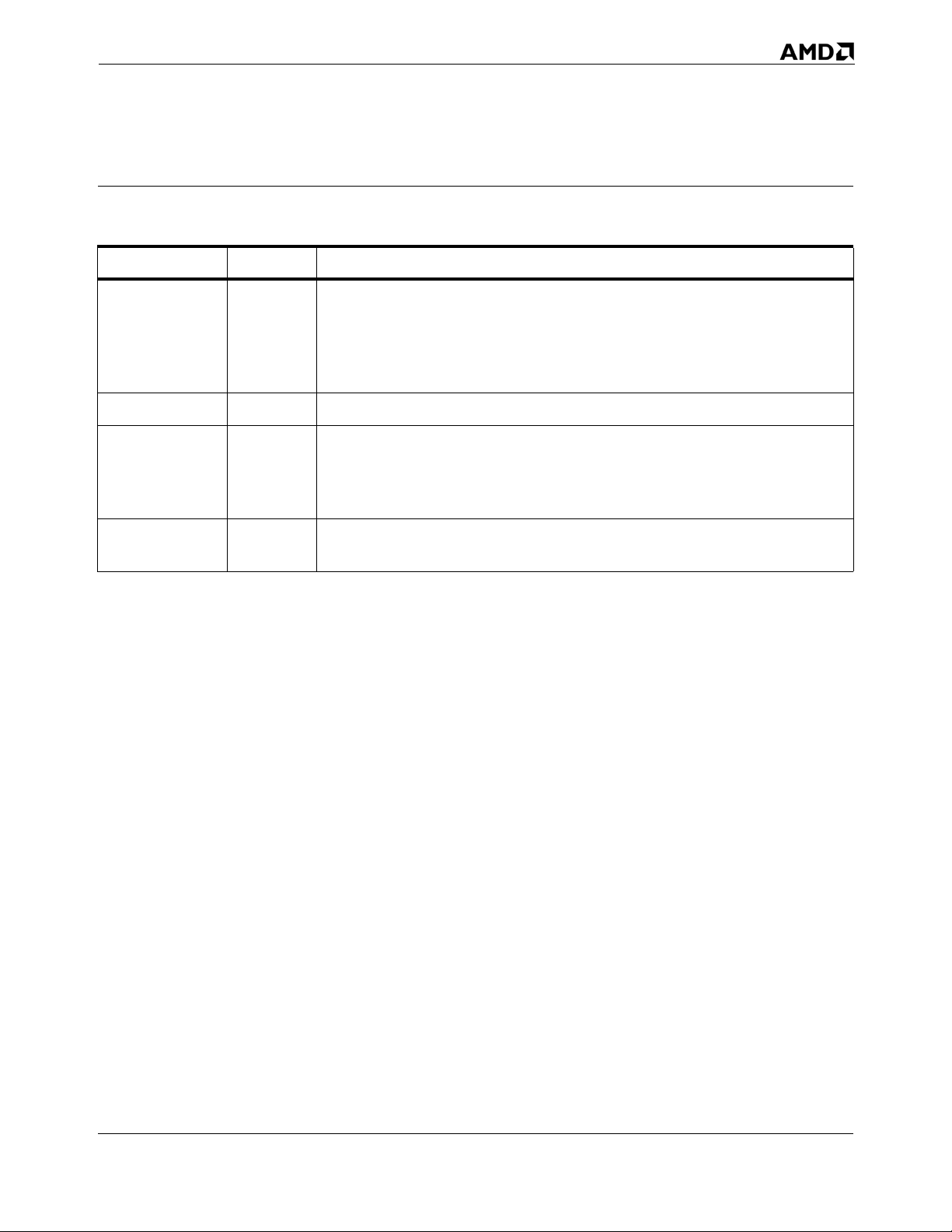
Revision History
Date Revision Description
Corrected Table 8-6, “General-Protection Exception Conditions”‚ on page 260.
Added SSE3 information. Clarified and corrected information on the CPUID
February 2005 3.10
September 2003 3.09 Corrected numerous minor typographical errors.
April 2003 3.08
instruction and feature identification. Added information on the RDTSCP
instruciton. Clarified information about MTRRs and PATs in multiprocessing
systems.
Clarified terms in section on FXSAVE/FXSTOR. Corrected several minor errors of
omission. Documentation of CR0.NW bit has been corrected. Several register
diagrams and figure labels have been corrected. Description of shared cache lines
has been clarified in Section 7.2.
September 2002 3.07
Made numerous small grammatical changes and factual clarifications. Added
Revision History.
Revision History xxi
Revision History xxi
Page 22

AMD64 Technology 24593—Rev. 3.10—February 2005
xxii Revision History
Page 23
24593—Rev. 3.10—February 2005 AMD64 Technology
Preface
About This Book
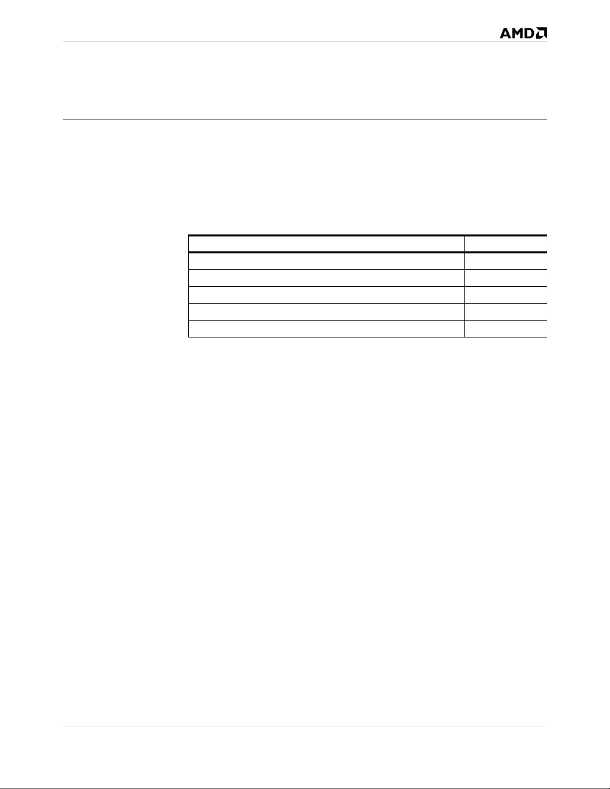
This book is part of a multivolume work entitled the AMD64
Architecture Programmer’s Manual. This table lists each volume
and its order number.
Title Order No.
Volume 1, Application Programming 24592
Volume 2, System Programming 24593
Volume 3, General-Purpose and System Instructions 24594
Volume 4, 128-Bit Media Instructions 26568
Volume 5, 64-Bit Media and x87 Floating-Point Instructions 26569
Audience
Contact Information
This volume (Volume 2) is intended for programmers writing
operating systems, loaders, linkers, device drivers, or system
utilities. It assumes an understanding of AMD64 architecture
application-level programming as described in Volume 1.
This volume describes the AMD64 architecture’s resources and
functions that are managed by system software, including
operating-mode control, memory management, interrupts and
exceptions, task and state-change management, systemmanagement mode (including power management), multiprocessor support, debugging, and processor initialization.
Application-programming topics are described in Volume 1.
Details about each instruction are described in volumes 3, 4,
and 5.
To submit questions or comments concerning this document,
contact our technical documentation staff at
[email protected].
Preface xxiii
Page 24

AMD64 Technology 24593—Rev. 3.10—February 2005
Organization
This volume begins with an overview of system programming
and differences between the x86 and AMD64 architectures.
This is followed by chapters that describe the following details
of system programming:
System Resources—The system registers and processor ID
(CPUID) functions.
Segmented Virtual Memory—The segmented-memory models
supported by the architecture and their associated data
structures and protection checks.
Page Translation and Protection—The page-translation
functions supported by the architecture and their associated
data structures and protection checks.
System-Management Instructions—The instructions used to
manage system functions.
Memory System—The memory-system hierarchy and its
resources and protocols, including memory-characterization,
caching, and buffering functions.
Exceptions and Interrupts—Details about the types and
causes of exceptions and interrupts, and the methods of
transferring control during these events.
Machine-Check Mechanism—The resources and functions
that support detection and handling of machine-check
errors.
System-Management Mode—The resources and functions
that support system-management mode (SMM), including
power-management functions.
128-Bit, 64-Bit, and x87 Programming—The resources and
functions that support use (by application software) and
state-saving (by the operation system) of the 128-bit media,
64-bit media, and x87 floating-point instructions.
Multiple-Processor Management—The features of the
instruction set and the system resources and functions that
support multiprocessing environments.
Debug and Performance Resources—The system resources and
functions that support software debugging and performance
monitoring.
xxiv Preface
Page 25

24593—Rev. 3.10—February 2005 AMD64 Technology
Legacy Task Management—Support for the legacy hardware
multitasking functions, including register resources and
data structures.
Processor Initialization and Long-Mode Activation—The
methods by which system software initializes and changes
operating modes.
Mixing Code Across Operating Modes—Things to remember
when running programs in different operating modes.
There are appendices describing details of model-specific
registers (MSRs) and machine-check implementations.
Definitions assumed throughout this volume are listed below.
The index at the end of this volume cross-references topics
within the volume. For other topics relating to the AMD64
architecture, see the tables of contents and indexes of the other
volumes.
Definitions
Some of the following definitions assume a knowledge of the
legacy x86 architecture. See “Related Documents” on
page xxxvi for descriptions of the legacy x86 architecture.
Terms and Notation 1011b
A binary value—in this example, a 4-bit value.
F0EAh
A hexadecimal value—in this example a 2-byte value.
[1,2)
A range that includes the left-most value (in this case, 1) but
excludes the right-most value (in this case, 2).
7–4
A bit range, from bit 7 to 4, inclusive. The high-order bit is
shown first.
128-bit media instructions
Instructions that use the 128-bit XMM registers. These are a
combination of the SSE, SSE2 and SSE3 instruction sets.
64-bit media instructions
Instructions that use the 64-bit MMX™ registers. These are
primarily a combination of MMX and 3DNow!™ instruction
Preface xxv
Page 26

AMD64 Technology 24593—Rev. 3.10—February 2005
sets, with some additional instructions from the SSE and
SSE2 instruction sets.
16-bit mode
Legacy mode or compatibility mode in which a 16-bit
address size is active. See legacy mode and compatibility
mode.
32-bit mode
Legacy mode or compatibility mode in which a 32-bit
address size is active. See legacy mode and compatibility
mode.
64-bit mode
A submode of long mode. In 64-bit mode, the default address
size is 64 bits and new features, such as register extensions,
are supported for system and application software.
#GP(0)
Notation indicating a general-protection exception (#GP)
with error code of 0.
absolute
Said of a displacement that references the base of a code
segment rather than an instruction pointer. Contrast with
relative.
biased exponent
The sum of a floating-point value’s exponent and a constant
bias for a particular floating-point data type. The bias makes
the range of the biased exponent always positive, which
allows reciprocation without overflow.
byte
Eight bits.
clear
To write a bit value of 0. Compare set.
compatibility mode
A submode of long mode. In compatibility mode, the default
address size is 32 bits, and legacy 16-bit and 32-bit
applications run without modification.
xxvi Preface
Page 27

24593—Rev. 3.10—February 2005 AMD64 Technology
commit
To irreversibly write, in program order, an instruction’s
result to software-visible storage, such as a register
(including flags), the data cache, an internal write buffer, or
memory.
CPL
Current privilege level.
CR0–CR4
A register range, from register CR0 through CR4, inclusive,
with the low-order register first.
CR0.PE = 1
Notation indicating that the PE bit of the CR0 register has a
value of 1.
direct
Referencing a memory location whose address is included in
the instruction’s syntax as an immediate operand. The
address may be an absolute or relative address. Compare
indirect.
dirty data
Data held in the processor’s caches or internal buffers that is
more recent than the copy held in main memory.
displacement
A signed value that is added to the base of a segment
(absolute addressing) or an instruction pointer (relative
addressing). Same as offset.
doubleword
Two words, or four bytes, or 32 bits.
double quadword
Eight words, or 16 bytes, or 128 bits. Also called octword.
DS:rSI
The contents of a memory location whose segment address is
in the DS register and whose offset relative to that segment
is in the rSI register.
Preface xxvii
Page 28

AMD64 Technology 24593—Rev. 3.10—February 2005
EFER.LME = 0
Notation indicating that the LME bit of the EFER register
has a value of 0.
effective address size
The address size for the current instruction after accounting
for the default address size and any address-size override
prefix.
effective operand size
The operand size for the current instruction after
accounting for the default operand size and any operandsize override prefix.
element
See vector.
exception
An abnormal condition that occurs as the result of executing
an instruction. The processor’s response to an exception
depends on the type of the exception. For all exceptions
except 128-bit media SIMD floating-point exceptions and
x87 floating-point exceptions, control is transferred to the
handler (or service routine) for that exception, as defined by
the exception’s vector. For floating-point exceptions defined
by the IEEE 754 standard, there are both masked and
unmasked responses. When unmasked, the exception
handler is called, and when masked, a default response is
provided instead of calling the handler.
FF /0
Notation indicating that FF is the first byte of an opcode,
and a subopcode in the ModR/M byte has a value of 0.
flush
An often ambiguous term meaning (1) writeback, if
modified, and invalidate, as in “flush the cache line,” or (2)
invalidate, as in “flush the pipeline,” or (3) change a value,
as in “flush to zero.”
GDT
Global descriptor table.
IDT
Interrupt descriptor table.
xxviii Preface
Page 29

24593—Rev. 3.10—February 2005 AMD64 Technology
IGN
Ignore. Field is ignored.
indirect
Referencing a memory location whose address is in a
register or other memory location. The address may be an
absolute or relative address. Compare direct.
IRB
The virtual-8086 mode interrupt-redirection bitmap.
IST
The long-mode interrupt-stack table.
IVT
The real-address mode interrupt-vector table.
LDT
Local descriptor table.
legacy x86
The legacy x86 architecture. See “Related Documents” on
page xxxvi for descriptions of the legacy x86 architecture.
legacy mode
An operating mode of the AMD64 architecture in which
existing 16-bit and 32-bit applications and operating systems
run without modification. A processor implementation of
the AMD64 architecture can run in either long mode or legacy
mode. Legacy mode has three submodes, real mode, protected
mode, and virtual-8086 mode.
long mode
An operating mode unique to the AMD64 architecture. A
processor implementation of the AMD64 architecture can
run in either long mode or legacy mode. Long mode has two
submodes, 64-bit mode and compatibility mode.
lsb
Least-significant bit.
LSB
Least-significant byte.
Preface xxix
Page 30

AMD64 Technology 24593—Rev. 3.10—February 2005
main memory
Physical memory, such as RAM and ROM (but not cache
memory) that is installed in a particular computer system.
mask
(1) A control bit that prevents the occurrence of a floatingpoint exception from invoking an exception-handling
routine. (2) A field of bits used for a control purpose.
MBZ
Must be zero. If software attempts to set an MBZ bit to 1, a
general-protection exception (#GP) occurs.
memory
Unless otherwise specified, main memory.
ModRM
A byte following an instruction opcode that specifies
address calculation based on mode (Mod), register (R), and
memory (M) variables.
moffset
A 16, 32, or 64-bit offset that specifies a memory operand
directly, without using a ModRM or SIB byte.
msb
Most-significant bit.
MSB
Most-significant byte.
multimedia instructions
A combination of 128-bit media instructions and 64-bit media
instructions.
octword
Same as double quadword.
offset
Same as displacement.
overflow
The condition in which a floating-point number is larger in
magnitude than the largest, finite, positive or negative
xxx Preface
Page 31

24593—Rev. 3.10—February 2005 AMD64 Technology
number that can be represented in the data-type format
being used.
packed
See vector.
PAE
Physical-address extensions.
physical memory
Actual memory, consisting of main memory and cache.
probe
A check for an address in a processor’s caches or internal
buffers. External probes originate outside the processor, and
internal probes originate within the processor.
protected mode
A submode of legacy mode.
quadword
Four words, or eight bytes, or 64 bits.
RAZ
Read as zero (0), regardless of what is written.
real-address mode
See real mode.
real mode
A short name for real-address mode, a submode of legacy
mode.
relative
Referencing with a displacement (also called offset) from an
instruction pointer rather than the base of a code segment.
Contrast with absolute.
reserved
Fields marked as reserved may be used at some future time.
To preserve compatibility with future processors, reserved
fields require special handling when read or written by
software.
Reserved fields may be further qualified as MBZ, RAZ, SBZ
or IGN (see definitions).
Preface xxxi
Page 32

AMD64 Technology 24593—Rev. 3.10—February 2005
Software must not depend on the state of a reserved field,
nor upon the ability of such fields to return to a previously
written state.
If a reserved field is not marked with one of the previous
qualifiers, software must not change the state of that field; it
must reload that field with the same values returned from a
prior read.
REX
An instruction prefix that specifies a 64-bit operand size and
provides access to additional registers.
RIP-relative addressing
Addressing relative to the 64-bit RIP instruction pointer.
set
To write a bit value of 1. Compare clear.
SIB
A byte following an instruction opcode that specifies
address calculation based on scale (S), index (I), and base
(B).
SIMD
Single instruction, multiple data. See vector.
SSE
Streaming SIMD extensions instruction set. See 128-bit
media instructions and 64-bit media instructions.
SSE2
Extensions to the SSE instruction set. See 128-bit media
instructions and 64-bit media instructions.
SSE3
Further extensions to the SSE instruction set. See 128-bit
media instructions.
sticky bit
A bit that is set or cleared by hardware and that remains in
that state until explicitly changed by software.
TOP
The x87 top-of-stack pointer.
xxxii Preface
Page 33

24593—Rev. 3.10—February 2005 AMD64 Technology
TPR
Task-priority register (CR8).
TSS
Task-state segment.
underflow
The condition in which a floating-point number is smaller in
magnitude than the smallest nonzero, positive or negative
number that can be represented in the data-type format
being used.
vector
(1) A set of integer or floating-point values, called elements,
that are packed into a single operand. Most of the 128-bit
and 64-bit media instructions use vectors as operands.
Vectors are also called packed or SIMD (single-instruction
multiple-data) operands.
(2) An index into an interrupt descriptor table (IDT), used to
access exception handlers. Compare exception.
virtual-8086 mode
A submode of legacy mode.
word
Two bytes, or 16 bits.
x86
See legacy x86.
Registers In the following list of registers, the names are used to refer
either to a given register or to the contents of that register:
AH–DH
The high 8-bit AH, BH, CH, and DH registers. Compare
AL–DL.
AL–DL
The low 8-bit AL, BL, CL, and DL registers. Compare AH–DH.
AL–r15B
The low 8-bit AL, BL, CL, DL, SIL, DIL, BPL, SPL, and
R8B–R15B registers, available in 64-bit mode.
Preface xxxiii
Page 34

AMD64 Technology 24593—Rev. 3.10—February 2005
BP
Base pointer register.
CRn
Control register number n.
CS
Code segment register.
eAX–eSP
The 16-bit AX, BX, CX, DX, DI, SI, BP, and SP registers or the
32-bit EAX, EBX, ECX, EDX, EDI, ESI, EBP, and ESP
registers. Compare rAX–rSP.
EBP
Extended base pointer register.
EFER
Extended features enable register.
eFLAGS
16-bit or 32-bit flags register. Compare rFLAGS.
EFLAGS
32-bit (extended) flags register.
eIP
16-bit or 32-bit instruction-pointer register. Compare rIP.
EIP
32-bit (extended) instruction-pointer register.
FLAGS
16-bit flags register.
GDTR
Global descriptor table register.
GPRs
General-purpose registers. For the 16-bit data size, these are
AX, BX, CX, DX, DI, SI, BP, and SP. For the 32-bit data size,
these are EAX, EBX, ECX, EDX, EDI, ESI, EBP, and ESP. For
the 64-bit data size, these include RAX, RBX, RCX, RDX,
RDI, RSI, RBP, RSP, and R8–R15.
xxxiv Preface
Page 35

24593—Rev. 3.10—February 2005 AMD64 Technology
IDTR
Interrupt descriptor table register.
IP
16-bit instruction-pointer register.
LDTR
Local descriptor table register.
MSR
Model-specific register.
r8–r15
The 8-bit R8B–R15B registers, or the 16-bit R8W–R15W
registers, or the 32-bit R8D–R15D registers, or the 64-bit
R8–R15 registers.
rAX–rSP
The 16-bit AX, BX, CX, DX, DI, SI, BP, and SP registers, or
the 32-bit EAX, EBX, ECX, EDX, EDI, ESI, EBP, and ESP
registers, or the 64-bit RAX, RBX, RCX, RDX, RDI, RSI,
RBP, and RSP registers. Replace the placeholder r with
nothing for 16-bit size, “E” for 32-bit size, or “R” for 64-bit
size.
RAX
64-bit version of the EAX register.
RAZ
Read as zero (0), regardless of what is written.
RBP
64-bit version of the EBP register.
RBX
64-bit version of the EBX register.
RCX
64-bit version of the ECX register.
RDI
64-bit version of the EDI register.
RDX
64-bit version of the EDX register.
Preface xxxv
Page 36

AMD64 Technology 24593—Rev. 3.10—February 2005
rFLAGS
16-bit, 32-bit, or 64-bit flags register. Compare RFLAGS.
RFLAGS
64-bit flags register. Compare rFLAGS.
rIP
16-bit, 32-bit, or 64-bit instruction-pointer register. Compare
RIP.
RIP
64-bit instruction-pointer register.
RSI
64-bit version of the ESI register.
RSP
64-bit version of the ESP register.
SP
Stack pointer register.
SS
Stack segment register.
TPR
Task priority register, a new register introduced in the
AMD64 architecture to speed interrupt management.
TR
Task register.
Endian Order The x86 and AMD64 architectures address memory using little-
endian byte-ordering. Multibyte values are stored with their
least-significant byte at the lowest byte address, and they are
illustrated with their least significant byte at the right side.
Strings are illustrated in reverse order, because the addresses of
their bytes increase from right to left.
Related Documents
Peter Abel, IBM PC Assembly Language and Programming,
Prentice-Hall, Englewood Cliffs, NJ, 1995.
Rakesh Agarwal, 80x86 Architecture & Programming: Volume
II, Prentice-Hall, Englewood Cliffs, NJ, 1991.
xxxvi Preface
Page 37

24593—Rev. 3.10—February 2005 AMD64 Technology
AMD data sheets and application notes for particular
hardware implementations of the AMD64 architecture.
AMD, AMD-K6™ MMX™ Enhanced Processor Multimedia
Technology, Sunnyvale, CA, 2000.
AMD, 3DNow!™ Technology Manual, Sunnyvale, CA, 2000.
AMD, AMD Extensions to the 3DNow!™ and MMX™
Instruction Sets, Sunnyvale, CA, 2000.
AMD, SYSCALL and SYSRET Instruction Specification
Application Note, Sunnyvale, CA, 1998.
Don Anderson and Tom Shanley, Pentium Processor System
Architecture, Addison-Wesley, New York, 1995.
Nabajyoti Barkakati and Randall Hyde, Microsoft Macro
Assembler Bible, Sams, Carmel, Indiana, 1992.
Barry B. Brey, 8086/8088, 80286, 80386, and 80486 Assembly
Language Programming, Macmillan Publishing Co., New
York, 1994.
Barry B. Brey, Programming the 80286, 80386, 80486, and
Pentium Based Personal Computer, Prentice-Hall, Englewood
Cliffs, NJ, 1995.
Ralf Brown and Jim Kyle, PC Interrupts, Addison-Wesley,
New York, 1994.
Penn Brumm and Don Brumm, 80386/80486 Assembly
Language Programming, Windcrest McGraw-Hill, 1993.
Geoff Chappell, DOS Internals, Addison-Wesley, New York,
1994.
Chips and Technologies, Inc. Super386 DX Programmer’s
Reference Manual, Chips and Technologies, Inc., San Jose,
1992.
John Crawford and Patrick Gelsinger, Programming the
80386, Sybex, San Francisco, 1987.
Cyrix Corporation, 5x86 Processor BIOS Writer's Guide, Cyrix
Corporation, Richardson, TX, 1995.
Cyrix Corporation, M1 Processor Data Book, Cyrix
Corporation, Richardson, TX, 1996.
Cyrix Corporation, MX Processor MMX Extension Opcode
Table, Cyrix Corporation, Richardson, TX, 1996.
Cyrix Corporation, MX Processor Data Book, Cyrix
Corporation, Richardson, TX, 1997.
Preface xxxvii
Page 38

AMD64 Technology 24593—Rev. 3.10—February 2005
Ray Duncan, Extending DOS: A Programmer's Guide to
Protected-Mode DOS, Addison Wesley, NY, 1991.
William B. Giles, Assembly Language Programming for the
Intel 80xxx Family, Macmillan, New York, 1991.
Frank van Gilluwe, The Undocumented PC, Addison-Wesley,
New York, 1994.
John L. Hennessy and David A. Patterson, Computer
Architecture, Morgan Kaufmann Publishers, San Mateo, CA,
1996.
Thom Hogan, The Programmer’s PC Sourcebook, Microsoft
Press, Redmond, WA, 1991.
Hal Katircioglu, Inside the 486, Pentium, and Pentium Pro,
Peer-to-Peer Communications, Menlo Park, CA, 1997.
IBM Corporation, 486SLC Microprocessor Data Sheet, IBM
Corporation, Essex Junction, VT, 1993.
IBM Corporation, 486SLC2 Microprocessor Data Sheet, IBM
Corporation, Essex Junction, VT, 1993.
IBM Corporation, 80486DX2 Processor Floating Point
Instructions, IBM Corporation, Essex Junction, VT, 1995.
IBM Corporation, 80486DX2 Processor BIOS Writer's Guide,
IBM Corporation, Essex Junction, VT, 1995.
IBM Corporation, Blue Lightening 486DX2 Data Book, IBM
Corporation, Essex Junction, VT, 1994.
Institute of Electrical and Electronics Engineers, IEEE
Standard for Binary Floating-Point Arithmetic, ANSI/IEEE
Std 754-1985.
Institute of Electrical and Electronics Engineers, IEEE
Standard for Radix-Independent Floating-Point Arithmetic,
ANSI/IEEE Std 854-1987.
Muhammad Ali Mazidi and Janice Gillispie Mazidi, 80X86
IBM PC and Compatible Computers, Prentice-Hall, Englewood
Cliffs, NJ, 1997.
Hans-Peter Messmer, The Indispensable Pentium Book,
Addison-Wesley, New York, 1995.
Karen Miller, An Assembly Language Introduction to
Computer Architecture: Using the Intel Pentium, Oxford
University Press, New York, 1999.
Stephen Morse, Eric Isaacson, and Douglas Albert, The
80386/387 Architecture, John Wiley & Sons, New York, 1987.
xxxviii Preface
Page 39

24593—Rev. 3.10—February 2005 AMD64 Technology
NexGen Inc., Nx586
TM
Processor Data Book, NexGen Inc.,
Milpitas, CA, 1993.
NexGen Inc., Nx686
TM
Processor Data Book, NexGen Inc.,
Milpitas, CA, 1994.
Bipin Patwardhan, Introduction to the Streaming SIMD
Extensions in the Pentium® III, www.x86.org/articles/sse_pt1/
simd1.htm, June, 2000.
Peter Norton, Peter Aitken, and Richard Wilton, PC
Programmer’s Bible, Microsoft Press, Redmond, WA, 1993.
PharLap 386|ASM Reference Manual, Pharlap, Cambridge
MA, 1993.
PharLap TNT DOS-Extender Reference Manual, Pharlap,
Cambridge MA, 1995.
Sen-Cuo Ro and Sheau-Chuen Her, i386/i486 Advanced
Programming, Van Nostrand Reinhold, New York, 1993.
Jeffrey P. Royer, Introduction to Protected Mode
Programming, course materials for an onsite class, 1992.
Tom Shanley, Protected Mode System Architecture, Addison
Wesley, NY, 1996.
SGS-Thomson Corporation, 80486DX Processor SMM
Programming Manual, SGS-Thomson Corporation, 1995.
Walter A. Triebel, The 80386DX Microprocessor, Prentice-
Hall, Englewood Cliffs, NJ, 1992.
John Wharton, The Complete x86, MicroDesign Resources,
Sebastopol, California, 1994.
Web sites and newsgroups:
- www.amd.com
- news.comp.arch
- news.comp.lang.asm.x86
- news.intel.microprocessors
- news.microsoft
Preface xxxix
Page 40

AMD64 Technology 24593—Rev. 3.10—February 2005
xl Preface
Page 41

24593—Rev. 3.10—February 2005 AMD64 Technology
1 System-Programming Overview
This entire volume is intended for system-software
developers—programmers writing operating systems, loaders,
linkers, device drivers, or utilities that require access to system
resources. These system resources are generally available only
to software running at the highest-privilege level (CPL=0), also
referred to as privileged software. Privilege levels and their
interactions are fully described in “Segment-Protection
Overview” on page 118.
This chapter introduces the basic features and capabilities of
the AMD64 architecture that are available to system-software
developers. The concepts include:
The supported address forms and how memory is organized.
How memory-management hardware makes use of the
various address forms to access memory.
The processor operating modes, and how the memory-
management hardware supports each of those modes.
The system-control registers used to manage system
resources.
The interrupt and exception mechanism, and how it is used
to interrupt program execution and to report errors.
Additional, miscellaneous features available to system
software, including support for hardware multitasking,
reporting machine-check exceptions, debugging software
problems, and optimizing software performance.
Many of the legacy features and capabilities are enhanced by
the AMD64 architecture to support 64-bit operating systems
and applications, while providing backward-compatibility with
existing software.
1.1 Memory Model
The AMD64 architecture memory model is designed to allow
system software to manage application software and associated
data in a secure fashion. The memory model is backwardcompatible with the legacy memory model. Hardwaretranslation mechanisms are provided to map addresses between
virtual-memory space and physical-memory space. The
Chapter 1: System-Programming Overview 1
Chapter 1: System-Programming Overview 1
Page 42

AMD64 Technology 24593—Rev. 3.10—February 2005
translation mechanisms allow system software to relocate
applications and data transparently, either anywhere in
physical-memory space, or in areas on the system hard drive
managed by the operating system.
In long mode, the AMD64 architecture implements a flatmemory model. In legacy mode, the architecture implements all
legacy memory models.
1.1.1 Memory Addressing
The AMD64 architecture supports address relocation. To do
this, several types of addresses are needed to completely
describe memory organization. Specifically, four types of
addresses are defined by the AMD64 architecture:
Logical addresses
Effective addresses, or segment offsets, which are a portion
of the logical address.
Linear (virtual) addresses
Physical addresses
Logical Addresses. A logical address is a reference into a
segmented-address space. It is comprised of the segment
selector and the effective address. Notationally, a logical
address is represented as
Logical Address = Segment Selector : Offset
The segment selector specifies an entry in either the global or
local descriptor table. The specified descriptor-table entry
describes the segment location in virtual-address space, its size,
and other characteristics. The effective address is used as an
offset into the segment specified by the selector.
Logical addresses are often referred to as far pointers. Far
pointers are used in software addressing when the segment
reference must be explicit (i.e., a reference to a segment
outside the current segment).
Effective Addresses. The offset into a memory segment is referred
to as an effective address (see “Segmentation” on page 6 for a
description of segmented memory). Effective addresses are
formed by adding together elements comprising a base value, a
scaled-index value, and a displacement value. The effectiveaddress computation is represented by the equation
Effective Address = Base + (Scale x Index) + Displacement
2 Chapter 1: System-Programming Overview
Page 43

24593—Rev. 3.10—February 2005 AMD64 Technology
The elements of an effective-address computation are defined
as follows:
Base—A value stored in any general-purpose register.
Scale—A positive value of 1, 2, 4, or 8.
Index—A two’s-complement value stored in any general-
purpose register.
Displacement—An 8-bit, 16-bit, or 32-bit two’s-complement
value encoded as part of the instruction.
Effective addresses are often referred to as near pointers. A near
pointer is used when the segment selector is known implicitly
or when the flat-memory model is used.
Long mode defines a 64-bit effective-address length. If a
processor implementation does not support the full 64-bit
virtual-address space, the effective address must be in canonical
form (see “Canonical Address Form” on page 5).
Linear (Virtual) Addresses. The segment-selector portion of a
logical address specifies a segment-descriptor entry in either
the global or local descriptor table. The specified segmentdescriptor entry contains the segment-base address, which is
the starting location of the segment in linear-address space. A
linear address is formed by adding the segment-base address to
the effective address (segment offset), which creates a
reference to any byte location within the supported linearaddress space. Linear addresses are often referred to as virtual
addresses, and both terms are used interchangeably throughout
this document.
Linear Address = Segment Base Address + Effective Address
When the flat-memory model is used—as in 64-bit mode—a
segment-base address is treated as 0. In this case, the linear
address is identical to the effective address. In long mode,
linear addresses must be in canonical address form, as
described in “Canonical Address Form” on page 5.
Physical Addresses. A physical address is a reference into the
physical-address space, typically main memory. Physical
addresses are translated from virtual addresses using pagetranslation mechanisms. See “Paging” on page 8 for
information on how the paging mechanism is used for virtualaddress to physical-address translation. When the paging
Chapter 1: System-Programming Overview 3
Chapter 1: System-Programming Overview 3
Page 44

AMD64 Technology 24593—Rev. 3.10—February 2005
mechanism is not enabled, the virtual (linear) address is used
as the physical address.
1.1.2 Memory Organization
The AMD64 architecture organizes memory into virtual memory and physical memory. Virtual-memory and physical-memory spaces can be (and usually are) different in size. Generally, the virtual-address space is much larger than physical-address memory. System software relocates applications and data between physical memory and the system hard disk to make it appear that much more memory is available than really exists. System software then uses the hardware memory-management mechanisms to map the larger virtual-address space into the smaller physical-address space.
Virtual Memory. Software uses virtual addresses to access
locations within the virtual-memory space. System software is
responsible for managing the relocation of applications and
data in virtual-memory space using segment-memory
management. System software is also responsible for mapping
virtual memory to physical memory through the use of page
translation. The AMD64 architecture supports different virtualmemory sizes using the following address-translation modes:
Protected Mode—This mode supports 4 gigabytes of virtual-
address space using 32-bit virtual addresses.
Long Mode—This mode supports 16 exabytes of virtual-
address space using 64-bit virtual addresses.
Physical Memory. Physical addresses are used to directly access
main memory. For a particular computer system, the size of the
available physical-address space is equal to the amount of main
memory installed in the system. The maximum amount of
physical memory accessible depends on the processor
implementation and on the address-translation mode. The
AMD64 architecture supports varying physical-memory sizes
using the following address-translation modes:
Real-Address Mode—This mode, also called real mode,
supports 1 megabyte of physical-address space using 20-bit
physical addresses. This address-translation mode is
described in “Real Addressing” on page 11. Real mode is
available only from legacy mode (see “Legacy Modes” on
page 16).
Legacy Protected Mode—This mode supports several different
address-space sizes, depending on the translation
4 Chapter 1: System-Programming Overview
Page 45

24593—Rev. 3.10—February 2005 AMD64 Technology
mechanism used and whether extensions to those
mechanisms are enabled.
Legacy protected mode supports 4 gigabytes of physicaladdress space using 32-bit physical addresses. Both segment
translation (see “Segmentation” on page 6) and page
translation (see “Paging” on page 8) can be used to access
the physical address space, when the processor is running in
legacy protected mode.
When the physical-address size extensions are enabled (see
“Physical-Address Extensions (PAE) Bit” on page 149), the
page-translation mechanism can be extended to support 52bit physical addresses. 52-bit physical addresses allow up to
4 petabytes of physical-address space to be supported.
(Currently, the AMD64 architecture supports 40-bit
addresses in this mode, allowing up to 1 terabyte of physicaladdress space to be supported.
Long Mode—This mode is unique to the AMD64 architecture.
This mode supports up to 4 petabytes of physical-address
space using 52-bit physical addresses. Long mode requires
the use of page-translation and the physical-address size
extensions (PAE).
1.1.3 Canonical Address Form
Long mode defines 64 bits of virtual-address space, but
processor implementations can support less. Although some
processor implementations do not use all 64 bits of the virtual
address, they all check bits 63 through the most-significant
implemented bit to see if those bits are all zeros or all ones. An
address that complies with this property is in canonical address
form. In most cases, a virtual-memory reference that is not in
canonical form causes a general-protection exception (#GP) to
occur. However, implied stack references where the stack
address is not in canonical form causes a stack exception (#SS)
to occur. Implied stack references include all push and pop
instructions, and any instruction using RSP or RBP as a base
register.
By checking canonical-address form, the AMD64 architecture
prevents software from exploiting unused high bits of pointers
for other purposes. Software complying with canonical-address
form on a specific processor implementation can run
unchanged on long-mode implementations supporting larger
virtual-address spaces.
Chapter 1: System-Programming Overview 5
Chapter 1: System-Programming Overview 5
Page 46

AMD64 Technology 24593—Rev. 3.10—February 2005
1.2 Memory Management
Memory management consists of the methods by which
addresses generated by software are translated by
segmentation and/or paging into addresses in physical memory.
Memory management is not visible to application software. It is
handled by the system software and processor hardware.
1.2.1 Segmentation Segmentation was originally created as a method by which
system software could isolate software processes (tasks), and
the data used by those processes, from one another in an effort
to increase the reliability of systems running multiple processes
simultaneously.
The AMD64 architecture is designed to support all forms of
legacy segmentation. However, most modern system software
does not use the segmentation features available in the legacy
x86 architecture. Instead, system software typically handles
program and data isolation using page-level protection. For this
reason, the AMD64 architecture dispenses with multiple
segments in 64-bit mode and, instead, uses a flat-memory
model. The elimination of segmentation allows new 64-bit
system software to be coded more simply, and it supports more
efficient management of multi-processing than is possible in
the legacy x86 architecture.
Segmentation is, however, used in compatibility mode and
legacy mode. Here, segmentation is a form of base memoryaddressing that allows software and data to be relocated in
virtual-address space off of an arbitrary base address. Software
and data can be relocated in virtual-address space using one or
more variable-sized memory segments. The legacy x86
architecture provides several methods of restricting access to
segments from other segments so that software and data can be
protected from interfering with each other.
In compatibility and legacy modes, up to 16,383 unique
segments can be defined. The base-address value, segment size
(called a limit), protection, and other attributes for each
segment are contained in a data structure called a segment
descriptor. Collections of segment descriptors are held in
descriptor tables. Specific segment descriptors are referenced or
selected from the descriptor table using a segment selector
register. Six segment-selector registers are available, providing
access to as many as six segments at a time.
6 Chapter 1: System-Programming Overview
Page 47
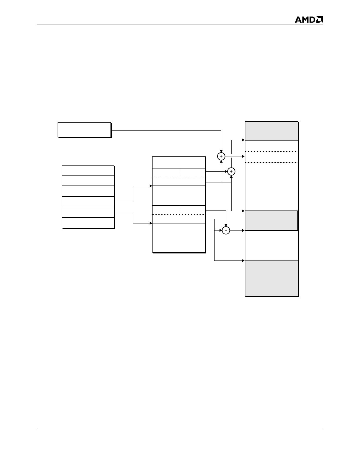
24593—Rev. 3.10—February 2005 AMD64 Technology
Figure 1-1 shows an example of segmented memory.
Segmentation is described in Chapter 4, “Segmented Virtual
Memory.”
Virtual Address
Space
Effective Address
Descriptor Table
Selectors
Virtual Address
CS
DS
ES
FS
GS
SS
Figure 1-1. Segmented-Memory Model
Limit
Base
Segment
Limit
Base
Segment
513-201.eps
Flat Segmentation. One special case of segmented memory is the flat-memory model. In the legacy flat-memory model, all segment-base addresses have a value of 0, and the segment limits are fixed at 4 Gbytes. Segmentation cannot be disabled but use of the flat-memory model effectively disables segment translation. The result is a virtual address that equals the effective address. Figure 1-2 on page 8 shows an example of the flat-memory model.
Chapter 1: System-Programming Overview 7
Chapter 1: System-Programming Overview 7
Page 48
AMD64 Technology 24593—Rev. 3.10—February 2005
Software running in 64-bit mode automatically uses the flatmemory model. In 64-bit mode, the segment base is treated as if
it were 0, and the segment limit is ignored. This allows an
effective addresses to access the full virtual-address space
supported by the processor.
Virtual Address
Space
Effective Address
Virtual Address
Flat Segment
513-202.eps
Figure 1-2. Flat Memory Model
1.2.2 Paging Paging allows software and data to be relocated in physical-
address space using fixed-size blocks called physical pages. The
legacy x86 architecture supports three different physical-page
sizes of 4 Kbytes, 2 Mbytes, and 4 Mbytes. As with segment
translation, access to physical pages by lesser-privileged
software can be restricted.
Page translation uses a hierarchical data structure called a
page-translation table to translate virtual pages into physicalpages. The number of levels in the translation-table hierarchy
can be as few as one or as many as four, depending on the
physical-page size and processor operating mode. Translation
tables are aligned on 4-Kbyte boundaries. Physical pages must
be aligned on 4-Kbyte, 2-Mbyte, or 4-Mbyte boundaries,
depending on the physical-page size.
8 Chapter 1: System-Programming Overview
Page 49
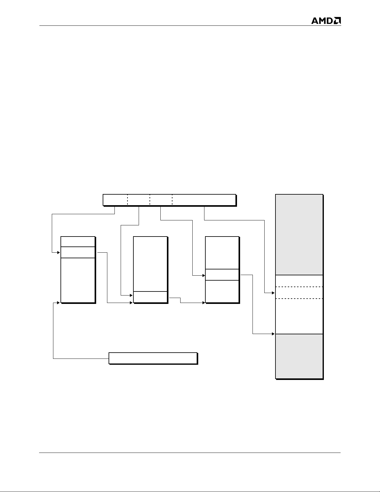
24593—Rev. 3.10—February 2005 AMD64 Technology
Each table in the translation hierarchy is indexed by a portion
of the virtual-address bits. The entry referenced by the table
index contains a pointer to the base address of the next-lowerlevel table in the translation hierarchy. In the case of the lowestlevel table, its entry points to the physical-page base address.
The physical page is then indexed by the least-significant bits
of the virtual address to yield the physical address.
Figure 1-3 shows an example of paged memory with three levels
in the translation-table hierarchy. Paging is described in
Chapter 5, “Page Translation and Protection.”
Physical Address
Virtual Address
Space
Physical Address
Table 3Table 2Table 1
Page Translation Tables
Physical Page
Page Table Base Address
513-203.eps
Figure 1-3. Paged Memory Model
Software running in long mode is required to have page
translation enabled.
Chapter 1: System-Programming Overview 9
Chapter 1: System-Programming Overview 9
Page 50

AMD64 Technology 24593—Rev. 3.10—February 2005
1.2.3 Mixing Segmentation and Paging
Memory-management software can combine the use of
segmented memory and paged memory. Because segmentation
cannot be disabled, paged-memory management requires some
minimum initialization of the segmentation resources. Paging
can be completely disabled, so segmented-memory
management does not require initialization of the paging
resources.
Segments can range in size from a single byte to 4 Gbytes in
length. It is therefore possible to map multiple segments to a
single physical page and to map multiple physical pages to a
single segment. Alignment between segment and physical-page
boundaries is not required, but memory-management software
is simplified when segment and physical-page boundaries are
aligned.
The simplest, most efficient method of memory management is
the flat-memory model. In the flat-memory model, all segment
base addresses have a value of 0 and the segment limits are
fixed at 4 Gbytes. The segmentation mechanism is still used
each time a memory reference is made, but because virtual
addresses are identical to effective addresses in this model, the
segmentation mechanism is effectively ignored. Translation of
virtual (or effective) addresses to physical addresses takes
place using the paging mechanism only.
Because 64-bit mode disables segmentation, it uses a flat,
paged-memory model for memory management. The 4 Gbyte
segment limit is ignored in 64-bit mode. Figure 1-4 on page 11
shows an example of this model.
10 Chapter 1: System-Programming Overview
Page 51
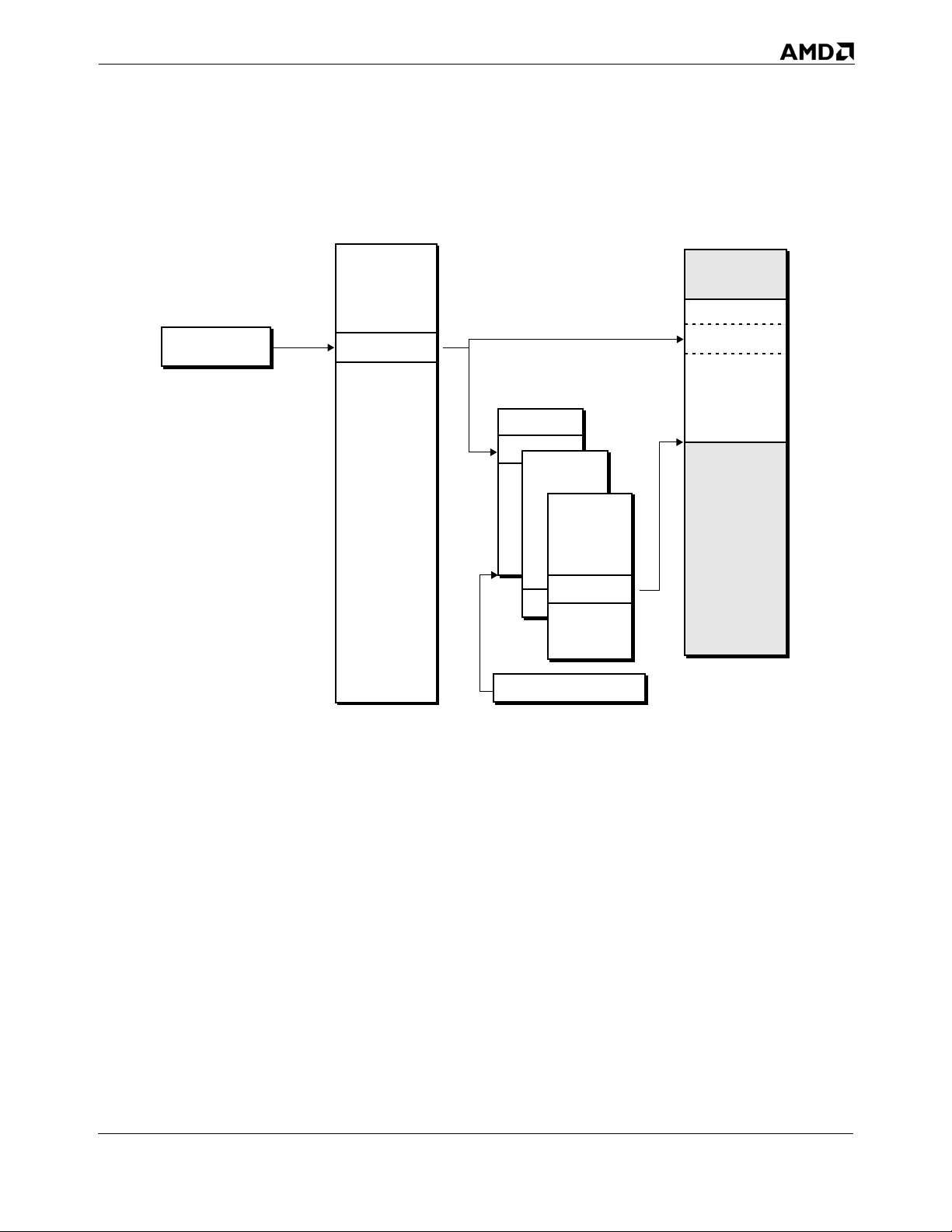
24593—Rev. 3.10—February 2005 AMD64 Technology
Effective Address
Virtual Address
Space
Virtual Address
Physical Address
Space
Physical Address
Page Translation Tables
Page Frame
Flat Segment
Page Table Base Address
513-204.eps
Figure 1-4. 64-Bit Flat, Paged-Memory Model
1.2.4 Real Addressing Real addressing is a legacy-mode form of address translation
used in real mode. This simplified form of address translation is
backward compatible with 8086-processor effective-to-physical
address translation. In this mode, 16-bit effective addresses are
mapped to 20-bit physical addresses, providing a 1-Mbyte
physical-address space.
Segment selectors are used in real-address translation, but not
as an index into a descriptor table. Instead, the 16-bit segmentselector value is shifted left by 4 bits to form a 20-bit segmentbase address. The 16-bit effective address is added to this 20-bit
segment base address to yield a 20-bit physical address. If the
sum of the segment base and effective address carries over into
bit 20, that bit can be optionally truncated to mimic the 20-bit
Chapter 1: System-Programming Overview 11
Chapter 1: System-Programming Overview 11
Page 52
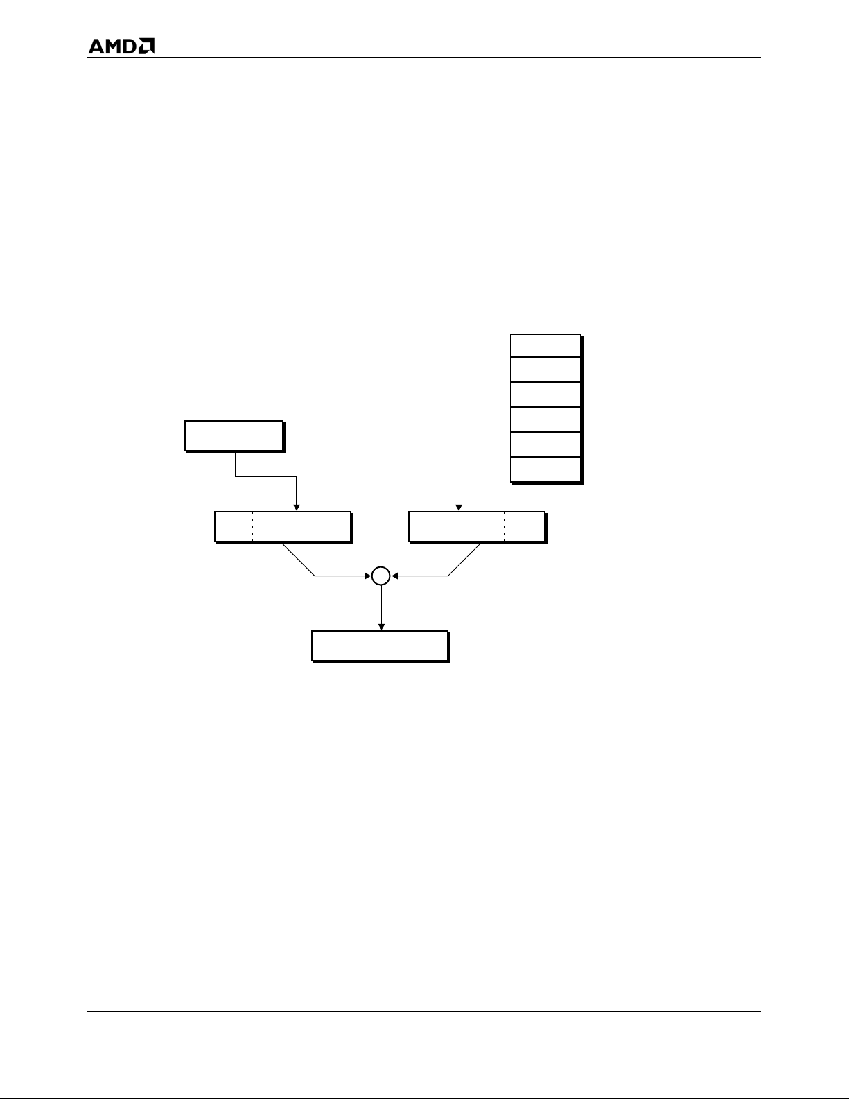
AMD64 Technology 24593—Rev. 3.10—February 2005
address wrapping of the 8086 processor by using the A20M#
input signal to mask the A20 address bit.
Real-address translation supports a 1-Mbyte physical-address
space using up to 64K segments aligned on 16-byte boundaries.
Each segment is exactly 64K bytes long. Figure 1-5 shows an
example of real-address translation.
Selectors
CS
DS
ES
015
Effective Address
FS
GS
SS
0000 Effective Address 0000Selector
Physical Address
Figure 1-5. Real-Address Memory Model
1.3 Operating Modes
The legacy x86 architecture provides four operating modes or
environments that support varying forms of memory
management, virtual-memory and physical-memory sizes, and
protection:
019019
+
019
513-205.eps
Real Mode.
Protected Mode.
Virtual-8086 Mode.
System Management Mode.
12 Chapter 1: System-Programming Overview
Page 53
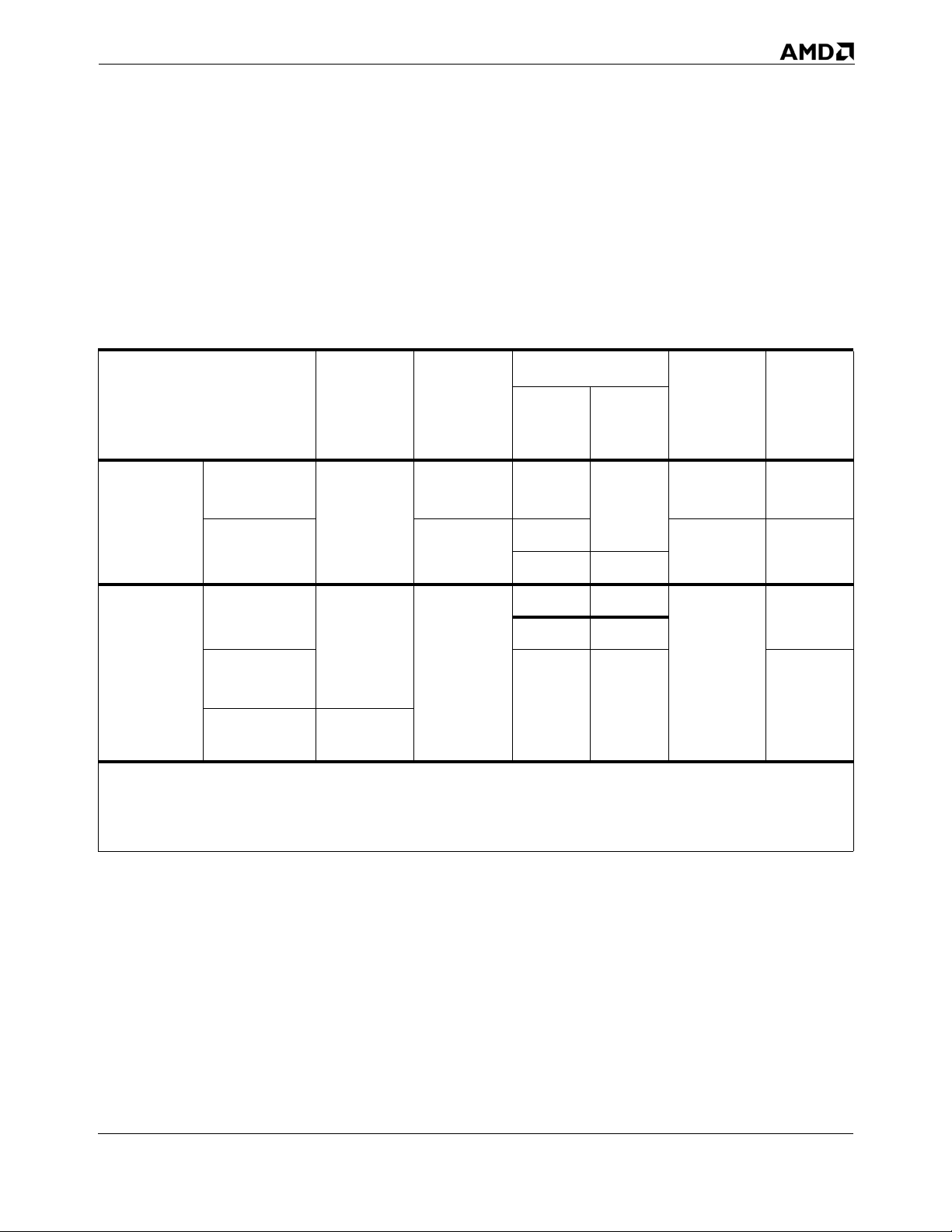
24593—Rev. 3.10—February 2005 AMD64 Technology
The AMD64 architecture supports all these legacy modes, and it
adds a new operating mode called long mode. Table 1-1 shows
the differences between long mode and legacy mode. Software
can move between all supported operating modes as shown in
Figure 1-6 on page 14. Each operating mode is described in the
following sections.
Table 1-1. Operating Modes
1
Operand
Size
(bits)
32
Long Mode
Legacy
Mode
Mode
64-Bit
Mode
3
Compatibility
Mode
Protected
Mode
Virtual-8086
Mode
System
Software
Required
New
64-bit OS
Legacy 32-
bit OS
Application
Recompile
Required
yes 64
no
no
Defaults
Address
Size
(bits)
32
16 16
32 32
16 16
16 16 32
Legacy 16-
Real Mode
Note:
1. Defaults can be overridden in most modes using an instruction prefix or system control bit.
2. Register extensions includes eight new GPRs and eight new XMM registers (also called SSE registers).
3. Long mode supports only x86 protected mode. It does not support x86 real mode or virtual-8086 mode.
bit OS
Register
Extensions
yes 64
no 32
no
Maximum
2
GPR
Width
(bits)
32
Chapter 1: System-Programming Overview 13
Chapter 1: System-Programming Overview 13
Page 54
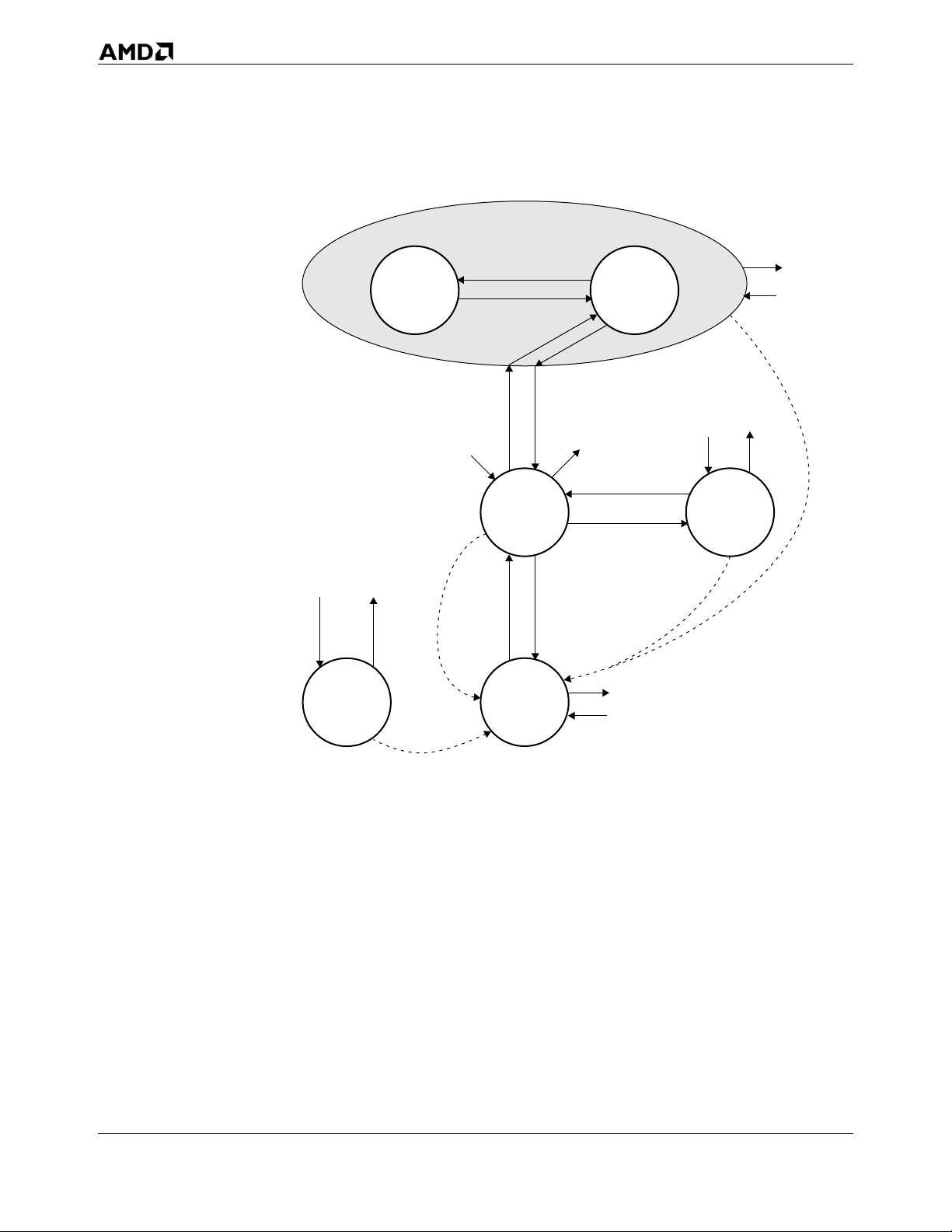
AMD64 Technology 24593—Rev. 3.10—February 2005
Long Mode
RSMSMI#
System
Management
Mode
64-bit
Mode
CS.L=0
EFER.LME=1, CR4.PAE=1
then CR0.PG=1
RSM
CR0.PE=1
Reset
Reset
CS.L=1
CS.L=0
Protected
Mode
Real
Mode
Compatibility
CR0.PG=0
then EFER.LME=0
SMI#
EFLAGS.VM=0
EFLAGS.VM=1
CR0.PE=0
SMI#
Mode
RSM
Reset
RSM
SMI#
RSM
SMI#
Reset
Virtual
8086
Mode
513-206.eps
Figure 1-6. Operating Modes of the AMD64 Architecture
1.3.1 Long Mode Long mode consists of two submodes: 64-bit mode and
compatibility mode. 64-bit mode supports several new features,
including the ability to address 64-bit virtual-address space.
Compatibility mode provides binary compatibility with existing
16-bit and 32-bit applications when running on 64-bit system
software.
Throughout this document, references to long mode refer
collectively to both 64-bit mode and compatibility mode. If a
function is specific to either 64-bit mode or compatibility mode,
then those specific names are used instead of the name long
mode.
14 Chapter 1: System-Programming Overview
Page 55

24593—Rev. 3.10—February 2005 AMD64 Technology
Before enabling and activating long mode, system software
must first enable protected mode. The process of enabling and
activating long mode is described in Chapter 14, “Processor
Initialization and Long-Mode Activation.” Long mode features
are described throughout this document, where applicable.
1.3.2 64-Bit Mode 64-bit mode, a submode of long mode, provides support for 64-
bit system software and applications by adding the following
new features:
64-bit virtual addresses (processor implementations can
have fewer).
Register extensions through a new instruction prefix (REX):
- Adds eight GPRs (R8–R15).
- Widens GPRs to 64 bits.
- Adds eight 128-bit streaming SIMD extension (SSE)
registers (XMM8–XMM15).
1.3.3 Compatibility Mode
64-bit instruction pointer (RIP).
New RIP-relative data-addressing mode.
Flat-segment address space with single code, data, and stack
space.
The mode is enabled by the system software on an individual
code-segment basis. Although code segments are used to enable
and disable 64-bit mode, the legacy segmentation mechanism is
largely disabled. Page translation is required for memory
management purposes. Because 64-bit mode supports a 64-bit
virtual-address space, it requires 64-bit system software and
development tools.
In 64-bit mode, the default address size is 64 bits, and the
default operand size is 32 bits. The defaults can be overridden
on an instruction-by-instruction basis using instruction
prefixes. A new REX prefix is introduced for specifying a 64-bit
operand size and the new registers.
Compatibility mode, a submode of long mode, allows system
software to implement binary compatibility with existing 16-bit
and 32-bit x86 applications. It allows these applications to run,
without recompilation, under 64-bit system software in long
mode, as shown in Table 1-1 on page 13.
In compatibility mode, applications can only access the first
4 Gbytes of virtual-address space. Standard x86 instruction
Chapter 1: System-Programming Overview 15
Chapter 1: System-Programming Overview 15
Page 56

AMD64 Technology 24593—Rev. 3.10—February 2005
prefixes toggle between 16-bit and 32-bit address and operand
sizes.
Compatibility mode, like 64-bit mode, is enabled by system
software on an individual code-segment basis. Unlike 64-bit
mode, however, segmentation functions the same as in the
legacy-x86 architecture, using 16-bit or 32-bit protected-mode
semantics. From an application viewpoint, compatibility mode
looks like a legacy protected-mode environment. From a
system-software viewpoint, the long-mode mechanisms are used
for address translation, interrupt and exception handling, and
system data-structures.
1.3.4 Legacy Modes Legacy mode consists of three submodes: real mode, protected
mode, and virtual-8086 mode. Protected mode can be either
paged or unpaged. Legacy mode preserves binary compatibility
not only with existing x86 16-bit and 32-bit applications but also
with existing x86 16-bit and 32-bit system software.
Real Mode. In this mode, also called real-address mode, the
processor supports a physical-memory space of 1 Mbyte and
operand sizes of 16 bits (default) or 32 bits (with instruction
prefixes). Interrupt handling and address generation are nearly
identical to the 80286 processor's real mode. Paging is not
supported. All software runs at privilege level 0.
Real mode is entered after reset or processor power-up. The
mode is not supported when the processor is operating in long
mode because long mode requires that paged protected mode
be enabled.
Protected Mode. In this mode, the processor supports virtualmemory and physical-memory spaces of 4 Gbytes and operand
sizes of 16 or 32 bits. All segment translation, segment
protection, and hardware multitasking functions are available.
System software can use segmentation to relocate effective
addresses in virtual-address space. If paging is not enabled,
virtual addresses are equal to physical addresses. Paging can be
optionally enabled to allow translation of virtual addresses to
physical addresses and to use the page-based memoryprotection mechanisms.
In protected mode, software runs at privilege levels 0, 1, 2, or 3.
Typically, application software runs at privilege level 3, the
system software runs at privilege levels 0 and 1, and privilege
16 Chapter 1: System-Programming Overview
Page 57

24593—Rev. 3.10—February 2005 AMD64 Technology
level 2 is available to system software for other uses. The 16-bit
version of this mode was first introduced in the 80286 processor.
Virtual-8086 Mode. Virtual-8086 mode allows system software to
run 16-bit real-mode software on a virtualized-8086 processor.
In this mode, software written for the 8086, 8088, 80186, or
80188 processor can run as a privilege-level-3 task under
protected mode. The processor supports a virtual-memory
space of 1 Mbytes and operand sizes of 16 bits (default) or 32
bits (with instruction prefixes), and it uses real-mode address
translation.
Virtual-8086 mode is enabled by setting the virtual-machine bit
in the EFLAGS register (EFLAGS.VM). EFLAGS.VM can only
be set or cleared when the EFLAGS register is loaded from the
TSS as a result of a task switch, or by executing an IRET
instruction from privileged software. The POPF instruction
cannot be used to set or clear the EFLAGS.VM bit.
1.3.5 System Management Mode (SMM)
Virtual-8086 mode is not supported when the processor is
operating in long mode. When long mode is enabled, any
attempt to enable virtual-8086 mode is silently ignored.
System management mode (SMM) is an operating mode
designed for system-control activities that are typically
transparent to conventional system software. Power
management is one popular use for system management mode.
SMM is primarily targeted for use by the basic input-output
system (BIOS) and specialized low-level device drivers. The
code and data for SMM are stored in the SMM memory area,
which is isolated from main memory by the SMM output signal.
SMM is entered by way of a system management interrupt
(SMI). Upon recognizing an SMI, the processor enters SMM and
switches to a separate address space where the SMM handler is
located and executes. In SMM, the processor supports realmode addressing with 4 Gbyte segment limits and default
operand, address, and stack sizes of 16 bits (prefixes can be
used to override these defaults).
1.4 System Registers
Figure 1-7 on page 19 shows the system registers defined for the
AMD64 architecture. System software uses these registers to,
among other things, manage the processor operating
Chapter 1: System-Programming Overview 17
Chapter 1: System-Programming Overview 17
Page 58

AMD64 Technology 24593—Rev. 3.10—February 2005
environment, define system resource characteristics, and to
monitor software execution. With the exception of the RFLAGS
register, system registers can be read and written only from
privileged software.
Except for the descriptor-table registers and task register, the
AMD64 architecture defines all system registers to be 64 bits
wide. The descriptor table and task registers are defined by the
AMD64 architecture to include 64-bit base-address fields, in
addition to their other fields.
As shown in Figure 1-7 on page 19, the system registers include:
Control Registers—These registers are used to control system
operation and some system features. See “System-Control
Registers” on page 51 for details.
System-Flags Register—The RFLAGS register contains
system-status flags and masks. It is also used to enable
virtual-8086 mode and to control application access to I/O
devices and interrupts. See “RFLAGS Register” on page 63
for details.
Descriptor-Table Registers—These registers contain the
location and size of descriptor tables stored in memory.
Descriptor tables hold segmentation data structures used in
protected mode. See “Descriptor Tables” on page 89 for
details.
Task Register—The task register contains the location and
size in memory of the task-state segment. The hardwaremultitasking mechanism uses the task-state segment to hold
state information for a given task. The TSS also holds other
data, such as the inner-level stack pointers used when
changing to a higher privilege level. See “Task Register” on
page 363 for details.
Debug Registers—Debug registers are used to control the
software-debug mechanism, and to report information back
to a debug utility or application. See “Debug Registers” on
page 385 for details.
18 Chapter 1: System-Programming Overview
Page 59
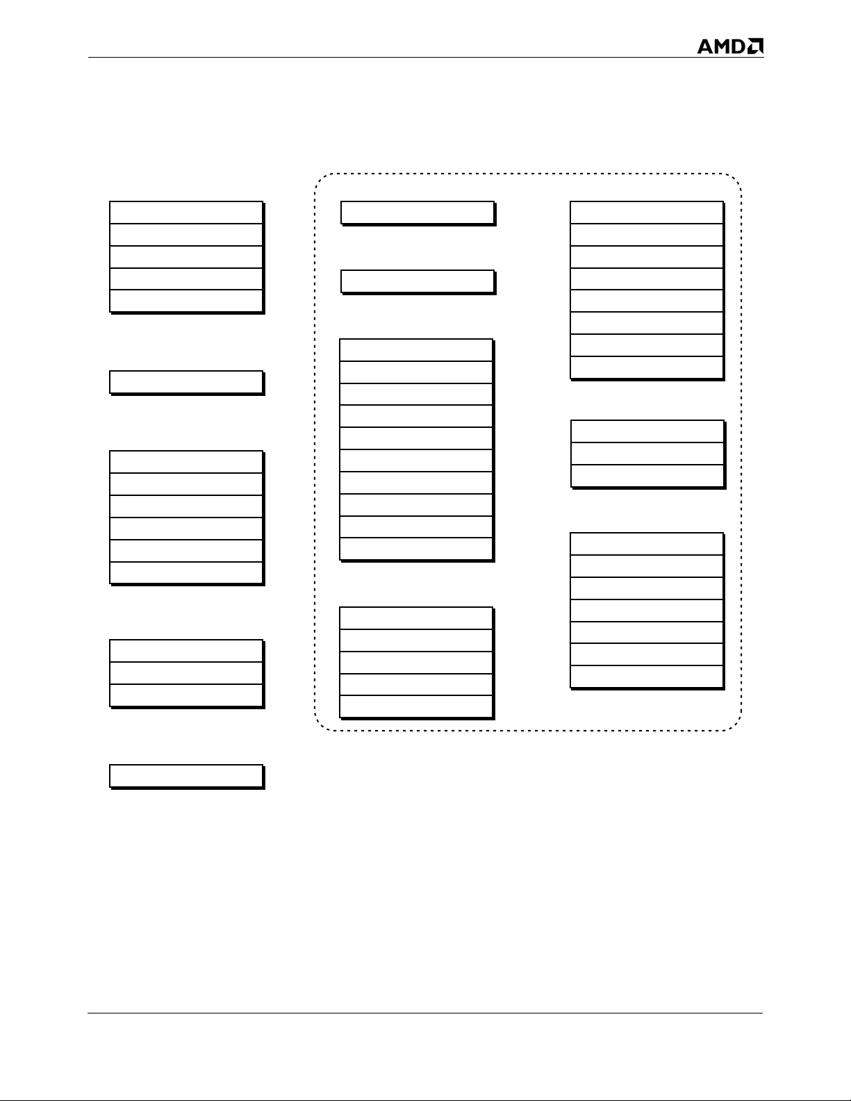
24593—Rev. 3.10—February 2005 AMD64 Technology
Control Registers
CR0
CR2
CR3
CR4
CR8
System-Flags Register
RFLAGS
Debug Registers
DR0
DR1
DR2
DR3
DR6
DR7
Descriptor-Table Registers
GDTR
IDTR
LDTR
Extended-Feature-Enable Register
EFER
System-Configuration Register
SYSCFG
System-Linkage Registers
STAR
LSTAR
CSTAR
SFMASK
FS.base
GS.base
KernelGSbase
SYSENTER_CS
SYSENTER_ESP
SYSENTER_EIP
Debug-Extension Registers
DebugCtlMSR
LastBranchFromIP
LastBranchToIP
LastIntFromIP
LastIntToIP
Memory-Typing Registers
MTRRcap
MTRRdefType
MTRRphysBasen
MTRRphysMaskn
MTRRfixn
PAT
TOP_MEM
TOP_MEM2
Performance-Monitoring Registers
TSC
PerfEvtSeln
PerfCtrn
Machine-Check Registers
MCG_CAP
MCG_STAT
MCG_CTL
MCi_CTL
MCi_STATUS
MCi_ADDR
MCi_MISC
Task Register
TR
Model-Specific Registers
513-260.eps
Figure 1-7. System Registers
Also defined as system registers are a number of model-specific
registers included in the AMD64 architectural definition, and
shown in Figure 1-7:
Extended-Feature-Enable Register—The EFER register is used
to enable and report status on special features not
controlled by the CRn control registers. In particular, EFER
Chapter 1: System-Programming Overview 19
Chapter 1: System-Programming Overview 19
Page 60

AMD64 Technology 24593—Rev. 3.10—February 2005
is used to control activation of long mode. See “Extended
Feature Enable Register (EFER)” on page 68 for more
information.
System-Configuration Register—The SYSCFG register is used
to enable and configure system-bus features. See “System
Configuration Register (SYSCFG)” on page 72 for more
information.
System-Linkage Registers—These registers are used by
system-linkage instructions to specify operating-system
entry points, stack locations, and pointers into system-data
structures. See “Fast System Call and Return” on page 181
for details.
Memory-Typing Registers—Memory-typing registers can be
used to characterize (type) system memory. Typing memory
gives system software control over how instructions and data
are cached, and how memory reads and writes are ordered.
See “MTRRs” on page 219 for details.
Debug-Extension Registers—These registers control
additional software-debug reporting features. See “Debug
Registers” on page 385 for details.
Performance-Monitoring Registers—Performance-monitoring
registers are used to count processor and system events, or
the duration of events. See “Performance Optimization” on
page 404 for more information.
Machine-Check Registers—The machine-check registers
control the response of the processor to non-recoverable
failures. They are also used to report information on such
failures back to system utilities designed to respond to such
failures. See “Machine Check MSRs” on page 307 for more
information.
1.5 System-Data Structures
Figure 1-8 on page 21 shows the system-data structures defined
for the AMD64 architecture. System-data structures are created
and maintained by system software for use by the processor
when running in protected mode. A processor running in
protected mode uses these data structures to manage memory
and protection, and to store program-state information when an
interrupt or task switch occurs.
20 Chapter 1: System-Programming Overview
Page 61
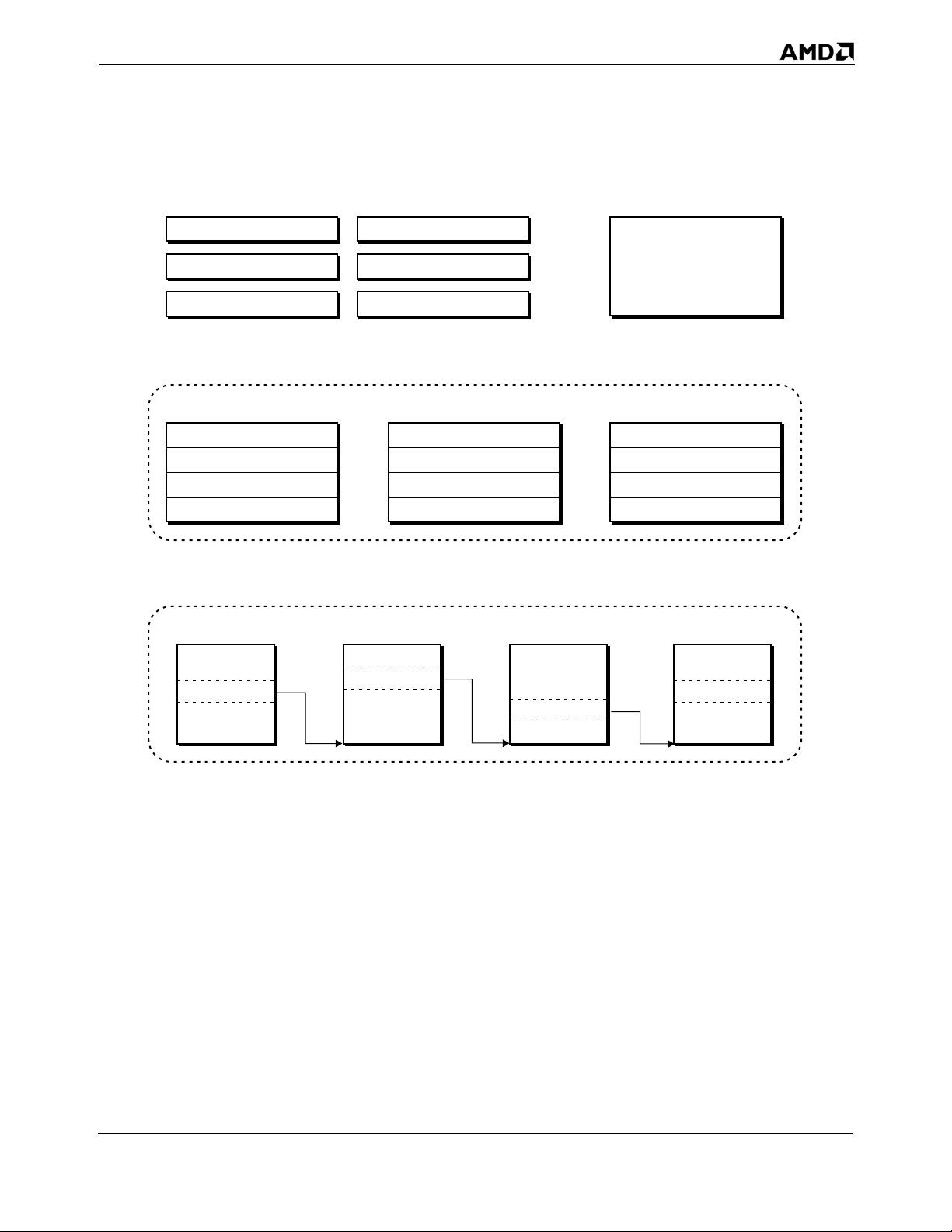
24593—Rev. 3.10—February 2005 AMD64 Technology
Segment Descriptors (Contained in Descriptor Tables)
Code
Stack
Data
Descriptor Tables
Global-Descriptor Table
Descriptor
Descriptor
. . .
Descriptor
Page-Translation Tables
Page-Map Level-4
Gate
Task-State Segment
Local-Descriptor Table
Interrupt-Descriptor Table
Gate Descriptor
Gate Descriptor
. . .
Gate Descriptor
Task-State Segment
Local-Descriptor Table
Descriptor
Descriptor
. . .
Descriptor
Page TablePage DirectoryPage-Directory Pointer
513-261.eps
Figure 1-8. System-Data Structures
As shown in Figure 1-8, the system-data structures include:
Descriptors—A descriptor provides information about a
segment to the processor, such as its location, size and
privilege level. A special type of descriptor, called a gate, is
used to provide a code selector and entry point for a
software routine. Any number of descriptors can be defined,
but system software must at a minimum create a descriptor
for the currently executing code segment and stack segment.
See “Legacy Segment Descriptors” on page 97, and “Long-
Chapter 1: System-Programming Overview 21
Chapter 1: System-Programming Overview 21
Page 62

AMD64 Technology 24593—Rev. 3.10—February 2005
Mode Segment Descriptors” on page 108 for complete
information on descriptors.
Descriptor Tables—As the name implies, descriptor tables
hold descriptors. The global-descriptor table holds
descriptors available to all programs, while a localdescriptor table holds descriptors used by a single program.
The interrupt-descriptor table holds only gate descriptors
used by interrupt handlers. System software must initialize
the global-descriptor and interrupt-descriptor tables, while
use of the local-descriptor table is optional. See “Descriptor
Tables” on page 89 for more information.
Task-State Segment—The task-state segment is a special
segment for holding processor-state information for a
specific program, or task. It also contains the stack pointers
used when switching to more-privileged programs. The
hardware multitasking mechanism uses the state
information in the segment when suspending and resuming
a task. Calls and interrupts that switch stacks cause the
stack pointers to be read from the task-state segment.
System software must create at least one task-state segment,
even if hardware multitasking is not used. See “Legacy TaskState Segment” on page 365, and “64-Bit Task State
Segment” on page 370 for details.
1.6 Interrupts
Page-Translation Tables—Use of page translation is optional
in protected mode, but it is required in long mode. A fourlevel page-translation data structure is provided to allow
long-mode operating systems to translate a 64-bit virtualaddress space into a 52-bit physical-address space. Legacy
protected mode can use two- or three-level page-translation
data structures. See “Page Translation Overview” on
page 146 for more information on page translation.
The AMD64 architecture provides a mechanism for the
processor to automatically suspend (interrupt) software
execution and transfer control to an interrupt handler when an
interrupt or exception occurs. An interrupt handler is
privileged software designed to identify and respond to the
cause of an interrupt or exception, and return control back to
the interrupted software. Interrupts can be caused when system
hardware signals an interrupt condition using one of the
external-interrupt signals on the processor. Interrupts can also
22 Chapter 1: System-Programming Overview
Page 63

24593—Rev. 3.10—February 2005 AMD64 Technology
be caused by software that executes an interrupt instruction.
Exceptions occur when the processor detects an abnormal
condition as a result of executing an instruction. The term
“interrupts” as used throughout this volume includes both
interrupts and exceptions when the distinction is unnecessary.
System software not only sets up the interrupt handlers, but it
must also create and initialize the data structures the processor
uses to execute an interrupt handler when an interrupt occurs.
The data structures include the code-segment descriptors for
the interrupt-handler software and any data-segment
descriptors for data and stack accesses. Interrupt-gate
descriptors must also be supplied. Interrupt gates point to
interrupt-handler code-segment descriptors, and the entry
point in an interrupt handler. Interrupt gates are stored in the
interrupt-descriptor table. The code-segment and data-segment
descriptors are stored in the global-descriptor table and,
optionally, the local-descriptor table.
When an interrupt occurs, the processor uses the interrupt
vector to find the appropriate interrupt gate in the interruptdescriptor table. The gate points to the interrupt-handler code
segment and entry point, and the processor transfers control to
that location. Before invoking the interrupt handler, the
processor saves information required to return to the
interrupted program. For details on how the processor transfers
control to interrupt handlers, see “Legacy Protected-Mode
Interrupt Control Transfers” on page 276, and “Long-Mode
Interrupt Control Transfers” on page 287.
Table 1-2 on page 24 shows the supported interrupts and
exceptions, ordered by their vector number. Refer to “Vectors”
on page 247 for a complete description of each interrupt, and a
description of the interrupt mechanism.
Chapter 1: System-Programming Overview 23
Chapter 1: System-Programming Overview 23
Page 64
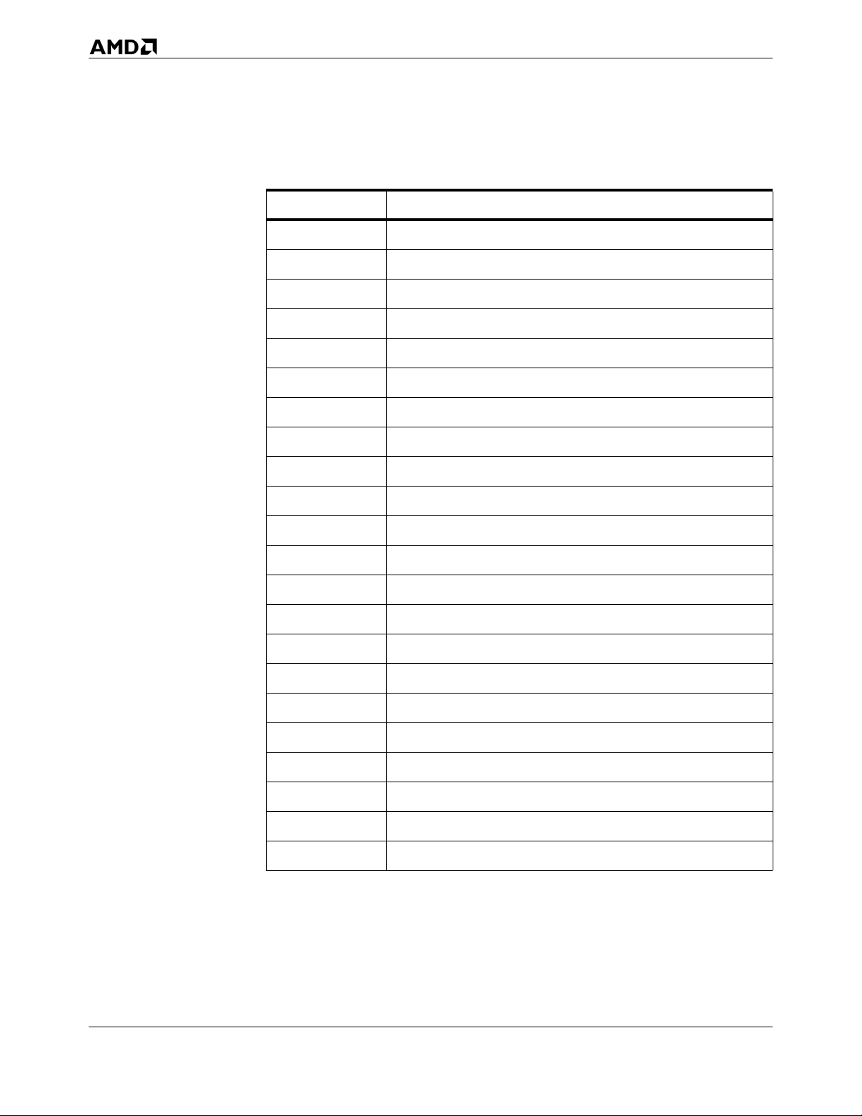
AMD64 Technology 24593—Rev. 3.10—February 2005
Table 1-2. Interrupts and Exceptions
Vector Description
0 Integer Divide-by-Zero Exception
1 Debug Exception
2 Non-Maskable-Interrupt
3 Breakpoint Exception (INT 3)
4 Overflow Exception (INTO instruction)
5 Bound-Range Exception (BOUND instruction)
6 Invalid-Opcode Exception
7 Device-Not-Available Exception
8 Double-Fault Exception
9 Coprocessor-Segment-Overrun Exception (reserved in AMD64)
10 Invalid-TSS Exception
11 Segment-Not-Present Exception
12 Stack Exception
13 General-Protection Exception
14 Page-Fault Exception
15 (Reserved)
16 x87 Floating-Point Exception
17 Alignment-Check Exception
18 Machine-Check Exception
19 SIMD Floating-Point Exception
0-255 Interrupt Instructions
Any Hardware Maskable Interrupts
1.7 Additional System-Programming Facilities
1.7.1 Hardware Multitasking
24 Chapter 1: System-Programming Overview
A task is any program that the processor can execute, suspend,
and later resume executing at the point of suspension. During
the time a task is suspended, other tasks are allowed to execute.
Page 65

24593—Rev. 3.10—February 2005 AMD64 Technology
Each task has its own execution space, consisting of a code
segment, data segments, and a stack segment for each privilege
level. Tasks can also have their own virtual-memory
environment managed by the page-translation mechanism. The
state information defining this execution space is stored in the
task-state segment (TSS) maintained for each task.
Support for hardware multitasking is provided by
implementations of the AMD64 architecture when software is
running in legacy mode. Hardware multitasking provides
automated mechanisms for switching tasks, saving the
execution state of the suspended task, and restoring the
execution state of the resumed task. When hardware
multitasking is used to switch tasks, the processor takes the
following actions:
The processor automatically suspends execution of the task,
allowing any executing instructions to complete and save
their results.
The execution state of a task is saved in the task TSS.
The execution state of a new task is loaded into the
processor from its TSS.
The processor begins executing the new task at the location
specified in the new task TSS.
Use of hardware-multitasking features is optional in legacy
mode. Generally, modern operating systems do not use the
hardware-multitasking features, and instead perform task
management entirely in software. Long mode does not support
hardware multitasking at all.
Whether hardware multitasking is used or not, system software
must create and initialize at least one task-state segment datastructure. This requirement holds for both long-mode and
legacy-mode software. The single task-state segment holds
critical pieces of the task execution environment and is
referenced during certain control transfers.
Detailed information on hardware multitasking is available in
Chapter 12, “Task Management,” along with a full description
of the requirements that must be met in initializing a task-state
segment when hardware multitasking is not used.
1.7.2 Machine Check Implementations of the AMD64 architecture support the
machine-check exception. This exception is useful in system
Chapter 1: System-Programming Overview 25
Chapter 1: System-Programming Overview 25
Page 66

AMD64 Technology 24593—Rev. 3.10—February 2005
applications with stringent requirements for reliability,
availability, and serviceability. The exception allows
specialized system-software utilities to report hardware errors
that are generally severe and non-recoverable. Providing the
capability to report such errors can allow complex system
problems to be pinpointed rapidly.
The machine-check exception is described in Chapter 9,
“Machine Check Mechanism.” Much of the error-reporting
capabilities is implementation dependent. For more
information, developers of machine-check error-reporting
software should also refer to the BIOS writer’s guide for a
specific implementation.
1.7.3 Software Debugging
A software-debugging mechanism is provided in hardware to
help software developers quickly isolate programming errors.
This capability can be used to debug system software and
application software alike. Only privileged software can access
the debugging facilities. Generally, software-debug support is
provided by a privileged application program rather than by the
operating system itself.
The facilities supported by the AMD64 architecture allow
debugging software to perform the following:
Set breakpoints on specific instructions within a program.
Set breakpoints on an instruction-address match.
Set breakpoints on a data-address match.
Set breakpoints on specific I/O-port addresses.
Set breakpoints to occur on task switches when hardware
multitasking is used.
Single step an application instruction-by-instruction.
Single step only branches and interrupts.
Record a history of branches and interrupts taken by a
program.
The debugging facilities are fully described in “Software-Debug
Resources” on page 384. Some processors provide additional,
implementation-specific debug support. For more information,
refer to the BIOS writer’s guide for the specific
implementation.
1.7.4 Performance Monitoring
For many software developers, the ability to identify and
eliminate performance bottlenecks from a program is nearly as
26 Chapter 1: System-Programming Overview
Page 67

24593—Rev. 3.10—February 2005 AMD64 Technology
important as quickly isolating programming errors.
Implementations of the AMD64 architecture provide hardware
performance-monitoring resources that can be used by special
software applications to identify such bottlenecks. Nonprivileged software can access the performance monitoring
facilities, but only if privileged software grants that access.
The performance-monitoring facilities allow the counting of
events, or the duration of events. Performance-analysis
software can use the data to calculate the frequency of certain
events, or the time spent performing specific activities. That
information can be used to suggest areas for improvement and
the types of optimizations that are helpful.
The performance-monitoring facilities are fully described in
“Performance Optimization” on page 404. The specific events
that can be monitored are generally implementation specific.
For more information, refer to the BIOS writer’s guide for the
specific implementation.
Chapter 1: System-Programming Overview 27
Chapter 1: System-Programming Overview 27
Page 68

AMD64 Technology 24593—Rev. 3.10—February 2005
28 Chapter 1: System-Programming Overview
Page 69

24593—Rev. 3.10—February 2005 AMD64 Technology
2 x86 and AMD64 Architecture Differences
The AMD64 architecture is designed to provide full binary
compatibility with all previous AMD implementations of the
x86 architecture. This chapter summarizes the new features and
architectural enhancements introduced by the AMD64
architecture, and compares those features and enhancements
with previous AMD x86 processors. Most of the new capabilities
introduced by the AMD64 architecture are available only in
long mode (64-bit mode, compatibility mode, or both). However,
some of the new capabilities are also available in legacy mode,
and are mentioned where appropriate.
The material throughout this chapter assumes the reader has a
solid understanding of the x86 architecture. For those who are
unfamiliar with the x86 architecture, please read the remainder
of this volume before reading this chapter.
2.1 Operating Modes
See “Operating Modes” on page 12 for a complete description
of the operating modes supported by the AMD64 architecture.
2.1.1 Long Mode The AMD64 architecture introduces long mode and its two sub-
modes: 64-bit mode and compatibility mode.
64-Bit Mode. 64-bit mode provides full support for 64-bit system
software and applications. The new features introduced in
support of 64-bit mode are summarized throughout this chapter.
To use 64-bit mode, a 64-bit operating system and tool chain are
required.
Compatibility Mode. Compatibility mode allows 64-bit operating
systems to implement binary compatibility with existing 16-bit
and 32-bit x86 applications. It allows these applications to run,
without recompilation, under control of a 64-bit operating
system in long mode. The architectural enhancements
introduced by the AMD64 architecture that support
compatibility mode are summarized throughout this chapter.
Unsupported Modes. Long mode does not support the following
two operating modes:
Chapter 2: x86 and AMD64 Architecture Differences 29
Page 70

AMD64 Technology 24593—Rev. 3.10—February 2005
Virtual-8086 Mode—The virtual-8086 mode bit
(EFLAGS.VM) is ignored when the processor is running in
long mode. When long mode is enabled, any attempt to
enable virtual-8086 mode is silently ignored. System
software must leave long mode in order to use virtual-8086
mode.
Real Mode—Real mode is not supported when the processor
is operating in long mode because long mode requires that
protected mode be enabled.
2.1.2 Legacy Mode The AMD64 architecture supports a pure x86 legacy mode,
which preserves binary compatibility not only with existing 16bit and 32-bit applications but also with existing 16-bit and 32bit operating systems. Legacy mode supports real mode,
protected mode, and virtual-8086 mode. A reset always places
the processor in legacy mode (real mode), and the processor
continues to run in legacy mode until system software activates
long mode. New features added by the AMD64 architecture that
are supported in legacy mode are summarized in this chapter.
2.1.3 SystemManagement Mode
The AMD64 architecture supports system-management mode
(SMM). SMM can be entered from both long mode and legacy
mode, and SMM can return directly to either mode. The
following differences exist between the support of SMM in the
AMD64 architecture and the SMM support found in previous
processor generations:
The SMRAM state-save area format is changed to hold the
64-bit processor state. This state-save area format is used
regardless of whether SMM is entered from long mode or
legacy mode.
The auto-halt restart and I/O-instruction restart entries in
the SMRAM state-save area are one byte instead of two
bytes.
The initial processor state upon entering SMM is expanded
to reflect the 64-bit nature of the processor.
New conditions exist that can cause a processor shutdown
while exiting SMM.
SMRAM caching considerations are modified because the
legacy FLUSH# external signal (writeback, if modified, and
invalidate) is not supported on implementations of the
AMD64 architecture.
30 Chapter 2: x86 and AMD64 Architecture Differences
Page 71

24593—Rev. 3.10—February 2005 AMD64 Technology
See Chapter 10, “System-Management Mode,” for more
information on the SMM differences.
2.2 Memory Model
The AMD64 architecture provides enhancements to the legacy
memory model to support very large physical-memory and
virtual-memory spaces while in long mode. Some of this
expanded support for physical memory is available in legacy
mode.
2.2.1 Memory Addressing
Virtual-Memory Addressing. Virtual-memory support is expanded
to 64 address bits in long mode. This allows up to 16 exabytes of
virtual-address space to be accessed. The virtual-address space
supported in legacy mode is unchanged.
Physical-Memory Addressing. Physical-memory support is expanded
to 52 address bits in long mode and legacy mode. This allows up
to 4 petabytes of physical memory to be accessed. The
expanded physical-memory support is achieved by using paging
and the page-size extensions.
Implementations can support fewer than 52 physical-address
bits. The first implementation of the AMD64 architecture, for
example, supports 40-bit physical addressing in both long mode
and legacy mode.
Effective Addressing. The effective-address length is expanded to 64 bits in long mode. An effective-address calculation uses 64bit base and index registers, and sign-extends 8-bit and 32-bit displacements to 64 bits. In legacy mode, effective addresses remain 32 bits long.
2.2.2 Page Translation The AMD64 architecture defines an expanded page-translation
mechanism supporting translation of a 64-bit virtual address to
a 52-bit physical address. See “Long-Mode Page Translation” on
page 160 for detailed information on the enhancements to page
translation in the AMD64 architecture. The enhancements are
summarized below.
Physical-Address Extensions (PAE). The AMD64 architecture requires
physical-address extensions to be enabled (CR4.PAE=1) before
long mode is entered. When PAE is enabled, all paging datastructures are 64 bits, allowing references into the full 52-bit
physical-address space supported by the architecture.
Chapter 2: x86 and AMD64 Architecture Differences 31
Page 72

AMD64 Technology 24593—Rev. 3.10—February 2005
Page-Size Extensions (PSE). Page-size extensions (CR4.PSE) are
ignored in long mode. Long mode does not support the 4-Mbyte
page size enabled by page-size extensions. Long mode does,
however, support 4-Kbyte and 2-Mbyte page sizes.
Paging Data Structures. The AMD64 architecture extends the pagetranslation data structures in support of long mode. The
extensions are:
Page-map level-4 (PML4)—Long mode defines a new page-
translation data structure, the PML4 table. The PML4 table
sits at the top of the page-translation hierarchy and
references PDP tables.
Page-directory pointer (PDP)—The PDP tables in long mode
are expanded from 4 entries to 512 entries each.
Page-directory pointer entry (PDPE)—Previously undefined
fields within the legacy-mode PDPE are defined by the
AMD64 architecture.
CR3 Register. The CR3 register is expanded to 64 bits for use in
long-mode page translation. When long mode is active, the CR3
register references the base address of the PML4 table. In
legacy mode, the upper 32 bits of CR3 are masked by the
processor to support legacy page translation. CR3 references
the PDP base-address when physical-address extensions are
enabled, or the page-directory table base-address when
physical-address extensions are disabled.
Legacy-Mode Enhancements. Legacy-mode software can take
advantage of the enhancements made to the physical-address
extension (PAE) support and page-size extension (PSE)
support. The four-level page translation mechanism introduced
by long mode is not available to legacy-mode software.
PA E—When physical-address extensions are enabled
(CR4.PAE=1), the AMD64 architecture allows legacy-mode
software to load up to 52-bit (maximum size) physical
addresses into the PDE and PTE. (Addresses are expanded
to the maximum physical address size supported by the
implementation.)
PSE—The use of page-size extensions allows legacy mode
software to define 4-Mbyte pages using the 32-bit pagetranslation tables. When page-size extensions are enabled
(CR4.PSE=1), the AMD64 architecture enhances the 4Mbyte PDE to support 40 physical-address bits.
32 Chapter 2: x86 and AMD64 Architecture Differences
Page 73

24593—Rev. 3.10—February 2005 AMD64 Technology
See “Legacy-Mode Page Translation” on page 150 for more
information on these enhancements.
2.2.3 Segmentation In long mode, the effects of segmentation depend on whether
the processor is running in compatibility mode or 64-bit mode:
In compatibility mode, segmentation functions just as it
does in legacy mode, using legacy 16-bit or 32-bit protected
mode semantics.
64-bit mode requires a flat-memory model for creating a flat
64-bit virtual-address space. Much of the segmentation
capability present in legacy mode and compatibility mode is
disabled when the processor is running in 64-bit mode.
The differences in the segmentation model as defined by the
AMD64 architecture are summarized in the following sections.
See Chapter 4, “Segmented Virtual Memory,” for a thorough
description of these differences.
Descriptor-Table Registers. In long mode, the base-address portion
of the descriptor-table registers (GDTR, IDTR, LDTR, and TR)
are expanded to 64 bits. The full 64-bit base address can only be
loaded by software when the processor is running in 64-bit
mode (using the LGDT, LIDT, LLDT, and LTR instructions,
respectively). However, the full 64-bit base address is used by a
processor running in compatibility mode (in addition to 64-bit
mode) when making a reference into a descriptor table.
A processor running in legacy mode can only load the low 32
bits of the base address, and the high 32 bits are ignored when
references are made to the descriptor tables.
Code-Segment Descriptors. The AMD64 architecture defines a new
code-segment descriptor attribute, L (long). In compatibility
mode, the processor treats code-segment descriptors as it does
in legacy mode, with the exception that the processor
recognizes the L attribute. If a code descriptor with L=1 is
loaded in compatibility mode, the processor leaves
compatibility mode and enters 64-bit mode. In legacy mode, the
L attribute is reserved.
The following differences exist for code-segment descriptors in
64-bit mode only:
The CS base-address field is ignored by the processor.
The CS limit field is ignored by the processor.
Chapter 2: x86 and AMD64 Architecture Differences 33
Page 74

AMD64 Technology 24593—Rev. 3.10—February 2005
Only the L (long), D (default size), and DPL (descriptor-
privilege level) fields are used by the processor in 64-bit
mode. All remaining attributes are ignored.
Data-Segment Descriptors. The following differences exist for datasegment descriptors in 64-bit mode only:
The DS, ES, and SS descriptor base-address fields are
ignored by the processor.
The FS and GS descriptor base-address fields are expanded
to 64 bits and used in effective-address calculations. The 64
bits of base address are mapped to model-specific registers
(MSRs), and can only be loaded using the WRMSR
instruction.
The limit fields and attribute fields of all data-segment
descriptors (DS, ES, FS, GS, and SS) are ignored by the
processor.
In compatibility mode, the processor treats data-segment
descriptors as it does in legacy mode. Compatibility mode
ignores the high 32 bits of base address in the FS and GS
segment descriptors when calculating an effective address.
System-Segment Descriptors. In 64-bit mode only, The LDT and TSS
system-segment descriptor formats are expanded by 64 bits,
allowing them to hold 64-bit base addresses. LLDT and LTR
instructions can be used to load these descriptors into the
LDTR and TR registers, respectively, from 64-bit mode.
In compatibility mode and legacy mode, the formats of the LDT
and TSS system-segment descriptors are unchanged. Also,
unlike code-segment and data-segment descriptors, systemsegment descriptor limits are checked by the processor in long
mode.
Some legacy mode LDT and TSS type-field encodings are illegal
in long mode (both compatibility mode and 64-bit mode), and
others are redefined to new types. See “System Descriptors” on
page 111 for additional information.
Gate Descriptors. The following differences exist between gate
descriptors in long mode (both compatibility mode and 64-bit
mode) and in legacy mode:
In long mode, all 32-bit gate descriptors are redefined as 64-
bit gate descriptors, and are expanded to hold 64-bit offsets.
34 Chapter 2: x86 and AMD64 Architecture Differences
Page 75

24593—Rev. 3.10—February 2005 AMD64 Technology
The length of a gate descriptor in long mode is therefore 128
bits (16 bytes), versus the 64 bits (8 bytes) in legacy mode.
Some type-field encodings are illegal in long mode, and
others are redefined to new types. See “Gate Descriptors”
on page 113 for additional information.
The interrupt-gate and trap-gate descriptors define a new
field, called the interrupt-stack table (IST) field.
2.3 Protection Checks
The AMD64 architecture makes the following changes to the
protection mechanism in long mode:
The page-protection-check mechanism is expanded in long
mode to include the U/S and R/W protection bits stored in
the PML4 entries and PDP entries.
Several system-segment types and gate-descriptor types that
are legal in legacy mode are illegal in long mode
(compatibility mode and 64-bit mode) and fail type checks
when used in long mode.
2.4 Registers
Segment-limit checks are disabled in 64-bit mode for the CS,
DS, ES, FS, GS, and SS segments. Segment-limit checks
remain enabled for the LDT, GDT, IDT and TSS system
segments.
All segment-limit checks are performed in compatibility
mode.
Code and data segments used in 64-bit mode are treated as
both readable and writable.
See “Page-Protection Checks” on page 174 and “SegmentProtection Overview” on page 118 for detailed information on
the protection-check changes.
The AMD64 architecture adds additional registers to the
architecture, and in many cases expands the size of existing
registers to 64 bits. The 80-bit floating-point stack registers and
their overlaid 64-bit MMX™ registers are not modified by the
AMD64 architecture.
2.4.1 General-Purpose Registers
In 64-bit mode, the general-purpose registers (GPRs) are 64 bits
wide, and eight additional GPRs are available. The GPRs are:
Chapter 2: x86 and AMD64 Architecture Differences 35
Page 76

AMD64 Technology 24593—Rev. 3.10—February 2005
RAX, RBX, RCX, RDX, RDI, RSI, RBP, RSP, and the new
R8–R15 registers. To access the full 64-bit operand size, or the
new R8–R15 registers, an instruction must include a new REX
instruction-prefix byte (see “REX Prefixes” on page 37 for a
summary of this prefix).
In compatibility and legacy modes, the GPRs consist only of the
eight legacy 32-bit registers. All legacy rules apply for
determining operand size.
2.4.2 128-Bit Media Registers
2.4.3 Flags Register The flags register is expanded to 64 bits, and is called RFLAGS.
2.4.4 Instruction
Pointer
2.4.5 Stack Pointer In 64-bit mode, the size of the stack pointer, RSP, is always 64
In 64-bit mode, eight additional 128-bit XMM registers are
available, XMM8–XMM15. A REX instruction prefix is used to
access these registers. In compatibility and legacy modes, the
XMM registers consist of the eight 128-bit legacy registers,
XMM0–XMM7.
All 64 bits can be accessed in 64-bit mode, but the upper 32 bits
are reserved and always read back as zeros. Compatibility mode
and legacy mode can read and write only the lower-32 bits of
RFLAGS (the legacy EFLAGS).
In long mode, the instruction pointer is extended to 64 bits, to
support 64-bit code offsets. This 64-bit instruction pointer is
called RIP.
bits. The stack size is not controlled by a bit in the SS
descriptor, as it is in compatibility or legacy mode, nor can it be
overridden by an instruction prefix. Address-size overrides are
ignored for implicit stack references.
2.4.6 Control Registers
2.4.7 Debug Registers In long mode, all debug registers are expanded to 64 bits,
36 Chapter 2: x86 and AMD64 Architecture Differences
The AMD64 architecture defines several enhancements to the
control registers (CRn). In long mode, all control registers are
expanded to 64 bits, although the entire 64 bits can be read and
written only from 64-bit mode. A new control register, the taskpriority register (CR8 or TPR) is added, and can be read and
written from 64-bit mode. Last, the function of the page-enable
bit (CR0.PG) is expanded. When long mode is enabled, the PG
bit is used to activate and deactivate long mode.
although the entire 64 bits can be read and written only from
64-bit mode. Expanded register encodings for the decode
registers allow up to eight new registers to be defined
Page 77

24593—Rev. 3.10—February 2005 AMD64 Technology
(DR8–DR15), although presently those registers are not
supported by the AMD64 architecture.
2.4.8 Extended Feature Register (EFER)
2.4.9 Memory Type Range Registers (MTRRs)
2.4.10 Other ModelSpecific Registers
(MSRs)
The EFER is expanded by the AMD64 architecture to include a
long-mode-enable bit (LME), and a long-mode-active bit (LMA).
These new bits can be accessed from legacy mode and long
mode.
The legacy MTRRs are architecturally defined as 64 bits, and
can accommodate the maximum 52-bit physical address allowed
by the AMD64 architecture. From both long mode and legacy
mode, implementations of the AMD64 architecture reference
the entire 52-bit physical-address value stored in the MTRRs.
Long mode and legacy mode system software can update all 64
bits of the MTRRs to manage the expanded physical-address
space.
Several other MSRs have fields holding physical addresses.
Examples include the APIC-base register and top-of-memory
register. Generally, any model-specific register that contains a
physical address is defined architecturally to be 64 bits wide,
and can accommodate the maximum physical-address size
defined by the AMD64 architecture. When physical addresses
are read from MSRs by the processor, the entire value is read
regardless of the operating mode. In legacy implementations,
the high-order MSR bits are reserved, and software must write
those values with zeros. In legacy mode on AMD64 architecture
implementations, software can read and write all supported
high-order MSR bits.
2.5 Instruction Set
2.5.1 REX Prefixes REX prefixes are a new family of instruction-prefix bytes used
in 64-bit mode to:
Specify the new GPRs and XMM registers.
Specify a 64-bit operand size.
Specify additional control registers. One additional control
register, CR8, is defined in 64-bit mode.
Specify additional debug registers (although none are
currently defined).
Not all instructions require a REX prefix. The prefix is
necessary only if an instruction references one of the extended
Chapter 2: x86 and AMD64 Architecture Differences 37
Page 78

AMD64 Technology 24593—Rev. 3.10—February 2005
registers or uses a 64-bit operand. If a REX prefix is used when
it has no meaning, it is ignored.
Default 64-Bit Operand Size. In 64-bit mode, two groups of
instructions have a default operand size of 64 bits and thus do
not need a REX prefix for this operand size:
Near branches.
All instructions, except far branches, that implicitly
reference the RSP. See “Instructions that Reference RSP”
on page 39 for additional information.
2.5.2 SegmentOverride Prefixes in
64-Bit Mode
2.5.3 Operands and Results
In 64-bit mode, the DS, ES, SS, and CS segment-override
prefixes have no effect. These four prefixes are no longer
treated as segment-override prefixes in the context of multipleprefix rules. Instead, they are treated as null prefixes.
The FS and GS segment-override prefixes are treated as
segment-override prefixes in 64-bit mode. Use of the FS and GS
prefixes cause their respective segment bases to be added to
the effective address calculation. See “FS and GS Registers in
64-Bit Mode” on page 88 for additional information on using
these segment registers.
The AMD64 architecture provides support for using 64-bit
operands and generating 64-bit results when operating in 64-bit
mode. See “Operands” in Volume 1 for details.
Operand-Size Overrides. In 64-bit mode, the default operand size is
32 bits. A REX prefix can be used to specify a 64-bit operand
size. Software uses a legacy operand-size (66h) prefix to toggle
to 16-bit operand size. The REX prefix takes precedence over
the legacy operand-size prefix.
Zero Extension of Results. In 64-bit mode, when performing 32-bit
operations with a GPR destination, the processor zero-extends
the 32-bit result into the full 64-bit destination. Both 8-bit and
16-bit operations on GPRs preserve all unwritten upper bits of
the destination GPR. This is consistent with legacy 16-bit and
32-bit semantics for partial-width results.
2.5.4 Address Calculations
The AMD64 architecture modifies aspects of effective-address
calculation to support 64-bit mode. These changes are
summarized in the following sections. See “Memory
Addressing” in Volume 1 for details.
38 Chapter 2: x86 and AMD64 Architecture Differences
Page 79

24593—Rev. 3.10—February 2005 AMD64 Technology
Address-Size Overrides. In 64-bit mode, the default-address size is
64 bits. The address size can be overridden to 32 bits by using
the address-size prefix (67h). 16-bit addresses are not supported
in 64-bit mode. In compatibility mode and legacy mode,
address-size overrides function the same as in x86 legacy
architecture.
Displacements and Immediates. Generally, displacement and
immediate values in 64-bit mode are not extended to 64 bits.
They are still limited to 32 bits and are sign extended during
effective-address calculations. In 64-bit mode, however, support
is provided for some 64-bit displacement and immediate forms
of the MOV instruction.
Zero Extending 16-Bit and 32-Bit Addresses. All 16-bit and 32-bit
address calculations are zero-extended in long mode to form 64bit addresses. Address calculations are first truncated to the
effective-address size of the current mode (64-bit mode or
compatibility mode), as overridden by any address-size prefix.
The result is then zero-extended to the full 64-bit address width.
2.5.5 Instructions that Reference RSP
RIP-Relative Addressing. A new addressing form, RIP-relative
(instruction-pointer relative) addressing, is implemented in 64bit mode. The effective address is formed by adding the
displacement to the 64-bit RIP of the next instruction.
With the exception of far branches, all instructions that
implicitly reference the 64-bit stack pointer, RSP, default to a
64-bit operand size in 64-bit mode (see Table 2-1 on page 40 for
a listing). Pushes and pops of 32-bit stack values are not
possible in 64-bit mode with these instructions, but they can be
overridden to 16 bits.
Chapter 2: x86 and AMD64 Architecture Differences 39
Page 80
AMD64 Technology 24593—Rev. 3.10—February 2005
Table 2-1. Instructions That Reference RSP
Mnemonic
ENTER C8 Create Procedure Stack Frame
LEAVE C9 Delete Procedure Stack Frame
POP reg/mem 8F/0 Pop Stack (register or memory)
POP reg 58-5F Pop Stack (register)
POP FS 0F A1 Pop Stack into FS Segment Register
POP GS 0F A9 Pop Stack into GS Segment Register
POPF, POPFD, POPFQ 9D
PUSH imm32 68
PUSH imm8 6A Push onto Stack (sign-extended byte)
PUSH reg/mem FF/6 Push onto Stack (register or memory)
PUSH reg 50-57 Push onto Stack (register)
Opcode
(hex)
Description
Pop to rFLAGS Word, Doubleword, or
Quadword
Push onto Stack (sign-extended
doubleword)
PUSH FS 0F A0 Push FS Segment Register onto Stack
PUSH GS 0F A8 Push GS Segment Register onto Stack
PUSHF, PUSHFD,
PUSHFQ
9C
Push rFLAGS Word, Doubleword, or
Quadword onto Stack
2.5.6 Branches The AMD64 architecture expands two branching mechanisms to
accommodate branches in the full 64-bit virtual-address space:
In 64-bit mode, near-branch semantics are redefined.
In both 64-bit and compatibility modes, a 64-bit call-gate
descriptor is defined for far calls.
In addition, enhancements are made to the legacy SYSCALL
and SYSRET instructions.
Near Branches. In 64-bit mode, the operand size for all near
branches defaults to 64 bits (see Table 2-2 on page 41 for a
listing). Therefore, these instructions update the full 64-bit RIP
without the need for a REX operand-size prefix. The following
aspects of near branches default to 64 bits:
40 Chapter 2: x86 and AMD64 Architecture Differences
Page 81
24593—Rev. 3.10—February 2005 AMD64 Technology
Truncation of the instruction pointer.
Size of a stack pop or stack push, resulting from a CALL or
RET.
Size of a stack-pointer increment or decrement, resulting
from a CALL or RET.
Size of operand fetched by indirect-branch operand size.
The operand size for near branches can be overridden to 16 bits
in 64-bit mode.
Table 2-2. 64-Bit Mode Near Branches, Default 64-Bit Operand Size
Mnemonic
CALL E8, FF/2 Call Procedure Near
Jcc many Jump Conditional Near
JMP E9, EB, FF/4 Jump Near
LOOP E2 Loop
LOOPcc E0, E1 Loop Conditional
RET C3, C2 Return From Call (near)
Opcode
(hex)
Description
The address size of near branches is not forced in 64-bit mode.
Such addresses are 64 bits by default, but they can be
overridden to 32 bits by a prefix.
The size of the displacement field for relative branches is still
limited to 32 bits.
Far Branches Through Long-Mode Call Gates. Long mode redefines the
32-bit call-gate descriptor type as a 64-bit call-gate descriptor
and expands the call-gate descriptor size to hold a 64-bit offset.
The long-mode call-gate descriptor allows far branches to
reference any location in the supported virtual-address space.
In long mode, the call-gate mechanism is changed as follows:
In long mode, CALL and JMP instructions that reference
call-gates must reference 64-bit call gates.
A 64-bit call-gate descriptor must reference a 64-bit code-
segment.
When a control transfer is made through a 64-bit call gate,
the 64-bit target address is read from the 64-bit call-gate
Chapter 2: x86 and AMD64 Architecture Differences 41
Page 82

AMD64 Technology 24593—Rev. 3.10—February 2005
descriptor. The base address in the target code-segment
descriptor is ignored.
Stack Switching. Automatic stack switching is also modified when
a control transfer occurs through a call gate in long mode:
The target-stack pointer read from the TSS is a 64-bit RSP
value.
The SS register is loaded with a null selector. Setting the
new SS selector to null allows nested control transfers in 64bit mode to be handled properly. The SS.RPL value is
updated to remain consistent with the newly loaded CPL
value.
The size of pushes onto the new stack is modified to
accommodate the 64-bit RIP and RSP values.
Automatic parameter copying is not supported in long mode.
Far Returns. In long mode, far returns can load a null SS selector
from the stack under the following conditions:
The target operating mode is 64-bit mode.
The target CPL<3.
Allowing RET to load SS with a null selector under these
conditions makes it possible for the processor to unnest far
CALLs (and interrupts) in long mode.
Task Gates. Control transfers through task gates are not
supported in long mode.
Branches to 64-Bit Offsets. Because immediate values are generally
limited to 32 bits, the only way a full 64-bit absolute RIP can be
specified in 64-bit mode is with an indirect branch. For this
reason, direct forms of far branches are eliminated from the
instruction set in 64-bit mode.
SYSCALL and SYSRET Instructions. The AMD64 architecture expands
the function of the legacy SYSCALL and SYSRET instructions
in long mode. In addition, two new STAR registers, LSTAR and
CSTAR, are provided to hold the 64-bit target RIP for the
instructions when they are executed in long mode. The legacy
STAR register is not expanded in long mode. See “SYSCALL
and SYSRET” on page 182 for additional information.
42 Chapter 2: x86 and AMD64 Architecture Differences
Page 83

24593—Rev. 3.10—February 2005 AMD64 Technology
SWAPGS Instruction. The AMD64 architecture provides the
SWAPGS instruction as a fast method for system software to
load a pointer to system data-structures. SWAPGS is valid only
in 64-bit mode. An undefined-opcode exception (#UD) occurs if
software attempts to execute SWAPGS in legacy mode or
compatibility mode. See “SWAPGS Instruction” on page 185
for additional information.
SYSENTER and SYSEXIT Instructions. The SYSENTER and SYSEXIT
instructions are invalid in long mode, and result in an invalid
opcode exception (#UD) if software attempts to use them.
Software should use the SYSCALL and SYSRET instructions
when running in long mode. See “SYSENTER and SYSEXIT
(Legacy Mode Only)” on page 184 for additional information.
2.5.7 NOP Instruction The legacy x86 architecture commonly uses opcode 90h as a
one-byte NOP. In 64-bit mode, the processor treats opcode 90h
specially in order to preserve this NOP definition. This is
necessary because opcode 90h is actually the XCHG EAX, EAX
instruction in the legacy architecture. Without special handling
in 64-bit mode, the instruction would not be a true no-operation.
Therefore, in 64-bit mode the processor treats opcode 90h (the
legacy XCHG EAX, EAX instruction) as a true NOP, regardless
of a REX operand-size prefix.
2.5.8 Single-Byte INC and DEC Instructions
2.5.9 MOVSXD Instruction
This special handling does not apply to the two-byte ModRM
form of the XCHG instruction. Unless a 64-bit operand size is
specified using a REX prefix byte, using the two-byte form of
XCHG to exchange a register with itself does not result in a nooperation, because the default operation size is 32 bits in 64-bit
mode.
In 64-bit mode, the legacy encodings for the 16 single-byte INC
and DEC instructions (one for each of the eight GPRs) are used
to encode the REX prefix values. The functionality of these INC
and DEC instructions is still available, however, using the
ModRM forms of those instructions (opcodes FF /0 and FF /1).
See “Single-Byte INC and DEC Instructions in 64-Bit Mode” in
Volume 3 for additional information.
MOVSXD is a new instruction in 64-bit mode (the legacy ARPL
instruction opcode, 63h, is reassigned as the MOVSXD opcode).
It reads a fixed-size 32-bit source operand from a register or
memory and (if a REX prefix is used with the instruction) signextends the value to 64 bits. MOVSXD is analogous to the
Chapter 2: x86 and AMD64 Architecture Differences 43
Page 84
AMD64 Technology 24593—Rev. 3.10—February 2005
MOVSX instruction, which sign-extends a byte to a word or a
word to a doubleword, depending on the effective operand size.
See “General-Purpose Instruction Reference” in Volume 3 for
additional information.
2.5.10 Invalid Instructions
Table 2-3 lists instructions that are illegal in 64-bit mode.
Table 2-4 on page 45 lists instructions that are invalid in long
mode (both compatibility mode and 64-bit mode). Attempted
use of these instructions causes an invalid-opcode exception
(#UD) to occur.
Table 2-3. Invalid Instructions in 64-Bit Mode
Mnemonic
AAA 37 ASCII Adjust After Addition
AAD D5 ASCII Adjust Before Division
AAM D4 ASCII Adjust After Multiply
AAS 3F ASCII Adjust After Subtraction
BOUND 62 Check Array Bounds
CALL (far) 9A Procedure Call Far (absolute)
DAA 27 Decimal Adjust after Addition
Opcode
(hex)
Description
DAS 2F Decimal Adjust after Subtraction
INTO CE Interrupt to Overflow Vector
JMP (far) EA Jump Far (absolute)
LDS C5 Load DS Segment Register
LES C4 Load ES Segment Register
POP DS 1F Pop Stack into DS Segment
POP ES 07 Pop Stack into ES Segment
POP SS 17 Pop Stack into SS Segment
POPA, POPAD 61 Pop All to GPR Words or Doublewords
PUSH CS 0E Push CS Segment Selector onto Stack
PUSH DS 1E Push DS Segment Selector onto Stack
PUSH ES 06 Push ES Segment Selector onto Stack
44 Chapter 2: x86 and AMD64 Architecture Differences
Page 85
24593—Rev. 3.10—February 2005 AMD64 Technology
Table 2-3. Invalid Instructions in 64-Bit Mode (continued)
Mnemonic
PUSH SS 16 Push SS Segment Selector onto Stack
PUSHA, PUSHAD 60 Push All GPR Words or Doublewords onto Stack
Redundant Grp1
(undocumented)
SALC
(undocumented)
Opcode
(hex)
82 Redundant encoding of group1 Eb,Ib opcodes
D6 Set AL According to CF
Description
Table 2-4. Invalid Instructions in Long Mode
Mnemonic
SYSENTER 0F 34 System Call
SYSEXIT 0F 35 System Return
Opcode
(hex)
Description
Table 2-5 lists the instructions that are no longer valid in 64-bit
mode because their opcodes have been reassigned. The
reassigned opcodes are used in 64-bit mode as REX instruction
prefixes.
Table 2-5. Reassigned Instructions in 64-Bit Mode
Opcode
(hex)
Description
Opcode for MOVSXD instruction in 64-bit mode.
In all other modes, this the Adjust Requestor
Privilege Level instruction opcode.
Decrement by 1, Increment by 1. Two-byte
versions of DEC and INC are still valid.
2.5.11 FXSAVE and FXRSTOR Instructions
Mnemonic
ARPL 63
DEC and INC 40-4F
The FXSAVE and FXRSTOR instructions are used to save and
restore the entire 128-bit media, 64-bit media, and x87
instruction-set environment during a context switch. The
AMD64 architecture modifies the memory format used by these
instructions in order to save and restore the full 64-bit
instruction and data pointers, as well as the XMM8–XMM15
Chapter 2: x86 and AMD64 Architecture Differences 45
Page 86

AMD64 Technology 24593—Rev. 3.10—February 2005
registers. Selection of the 32-bit legacy format or the expanded
64-bit format is accomplished by using the corresponding
operand size with the FXSAVE and FXRSTOR instructions.
When 64-bit software executes an FXSAVE and FXRSTOR with
a 32-bit operand size (no operand-size override) the 32-bit
legacy format is used. When 64-bit software executes an
FXSAVE and FXRSTOR with a 64-bit operand size, the 64-bit
format is used.
If the fast-FXSAVE/FXRSTOR (FFXSR) feature is enabled in
EFER, FXSAVE and FXRSTOR do not save or restore the
XMM0-XMM15 registers when executed in 64-bit mode at
CPL 0. The x87 environment and MXCSR are saved whether
fast-FXSAVE/FXRSTOR is enabled or not. Software can use
CPUID to determine whether the fast-FXSAVE/FXRSTOR
feature is available (CPUID function 8000_0001h, EDX bit 25).
The fast-FXSAVE/FXRSTOR feature has no effect on
FXSAVE/FXRSTOR in non 64-bit mode or when CPL > 0.
2.6 Interrupts and Exceptions
When a processor is running in long mode, an interrupt or
exception causes the processor to enter 64-bit mode. All longmode interrupt handlers must be implemented as 64-bit code.
The AMD64 architecture expands the legacy interruptprocessing and exception-processing mechanism to support
handling of interrupts by 64-bit operating systems and
applications. The changes are summarized in the following
sections. See “Long-Mode Interrupt Control Transfers” on
page 287 for detailed information on these changes.
2.6.1 Interrupt Descriptor Table
2.6.2 Stack Frame Pushes
The long-mode interrupt-descriptor table (IDT) must contain
64-bit mode interrupt-gate or trap-gate descriptors for all
interrupts or exceptions that can occur while the processor is
running in long mode. Task gates cannot be used in the longmode IDT, because control transfers through task gates are not
supported in long mode. In long mode, the IDT index is formed
by scaling the interrupt vector by 16. In legacy protected mode,
the IDT is indexed by scaling the interrupt vector by eight.
In legacy mode, the size of an IDT entry (16 bits or 32 bits)
determines the size of interrupt-stack-frame pushes, and
SS:eSP is pushed only on a CPL change. In long mode, the size
of interrupt stack-frame pushes is fixed at eight bytes, because
46 Chapter 2: x86 and AMD64 Architecture Differences
Page 87

24593—Rev. 3.10—February 2005 AMD64 Technology
interrupts are handled in 64-bit mode. Long mode interrupts
also cause SS:RSP to be pushed unconditionally, rather than
pushing only on a CPL change.
2.6.3 Stack Switching Legacy mode provides a mechanism to automatically switch
stack frames in response to an interrupt. In long mode, a
slightly modified version of the legacy stack-switching
mechanism is implemented, and an alternative stack-switching
mechanism—called the interrupt stack table (IST)—is
supported.
Long-Mode Stack Switches. When stacks are switched as part of a
long-mode privilege-level change resulting from an interrupt,
the following occurs:
The target-stack pointer read from the TSS is a 64-bit RSP
value.
The SS register is loaded with a null selector. Setting the
new SS selector to null allows nested control transfers in 64bit mode to be handled properly. The SS.RPL value is
cleared to 0.
The old SS and RSP are saved on the new stack.
Interrupt Stack Table. In long mode, a new interrupt stack table
(IST) mechanism is available as an alternative to the modified
legacy stack-switching mechanism. The IST mechanism
unconditionally switches stacks when it is enabled. It can be
enabled for individual interrupt vectors using a field in the IDT
entry. This allows mixing interrupt vectors that use the
modified legacy mechanism with vectors that use the IST
mechanism. The IST pointers are stored in the long-mode TSS.
The IST mechanism is only available when long mode is
enabled.
2.6.4 IRET Instruction In compatibility mode, IRET pops SS:eSP off the stack only if
there is a CPL change. This allows legacy applications to run
properly in compatibility mode when using the IRET
instruction.
In 64-bit mode, IRET unconditionally pops SS:eSP off of the
interrupt stack frame, even if the CPL does not change. This is
done because the original interrupt always pushes SS:RSP.
Because interrupt stack-frame pushes are always eight bytes in
long mode, an IRET from a long-mode interrupt handler (64-bit
code) must pop eight-byte items off the stack. This is
Chapter 2: x86 and AMD64 Architecture Differences 47
Page 88

AMD64 Technology 24593—Rev. 3.10—February 2005
accomplished by preceding the IRET with a 64-bit REX
operand-size prefix.
In long mode, an IRET can load a null SS selector from the stack
under the following conditions:
The target operating mode is 64-bit mode.
The target CPL<3.
Allowing IRET to load SS with a null selector under these
conditions makes it possible for the processor to unnest
interrupts (and far CALLs) in long mode.
2.6.5 Task-Priority Register (CR8)
The AMD64 architecture allows software to define up to 15
external interrupt-priority classes. Priority classes are
numbered from 1 to 15, with priority-class 1 being the lowest
and priority-class 15 the highest.
A new control register (CR8) is introduced by the AMD64
architecture for managing priority classes. This register, also
called the task-priority register (TPR), uses the four low-order
bits for specifying a task priority. How external interrupts are
organized into these priority classes is implementation
dependent. See “External Interrupt Priorities” on page 272 for
information on this feature.
2.6.6 New Exception Conditions
The AMD64 architecture defines a number of new conditions
that can cause an exception to occur when the processor is
running in long mode. Many of the conditions occur when
software attempts to use an address that is not in canonical
form. See “Vectors” on page 247 for information on the new
exception conditions that can occur in long mode.
2.7 Hardware Task Switching
The legacy hardware task-switch mechanism is disabled when
the processor is running in long mode. However, long mode
requires system software to create data structures for a single
task—the long-mode task.
TSS Descriptors—A new TSS-descriptor type, the 64-bit TSS
type, is defined for use in long mode. It is the only valid TSS
type that can be used in long mode, and it must be loaded
into the TR by executing the LTR instruction in 64-bit mode.
See “TSS Descriptor” on page 362 for additional
information.
48 Chapter 2: x86 and AMD64 Architecture Differences
Page 89

24593—Rev. 3.10—February 2005 AMD64 Technology
Task Gates—Because the legacy task-switch mechanism is
not supported in long mode, software cannot use task gates in
long mode. Any attempt to transfer control to another task
through a task gate causes a general-protection exception
(#GP) to occur.
Task-State Segment—A 64-bit task state segment (TSS) is
defined for use in long mode. This new TSS format contains
64-bit stack pointers (RSP) for privilege levels 0–2,
interrupt-stack-table (IST) pointers, and the I/O-map base
address. See “64-Bit Task State Segment” on page 370 for
additional information.
2.8 Long-Mode vs. Legacy-Mode Differences
Table 2-6 on page 50 summarizes several major systemprogramming differences between 64-bit mode and legacy
protected mode. The third column indicates whether the
difference also applies to compatibility mode. “Differences
Between Long Mode and Legacy Mode” in Volume 3
summarizes the application-programming model differences.
Chapter 2: x86 and AMD64 Architecture Differences 49
Page 90
AMD64 Technology 24593—Rev. 3.10—February 2005
Table 2-6. Differences Between Long Mode and Legacy Mode
Applies To
Subject 64-Bit Mode Difference
x86 Modes Real and virtual-8086 modes not supported Yes
Task Switching Task switching not supported Yes
64-bit virtual addresses No
Compatibility
Mode?
Addressing
Loaded Segment (Usage
during memory reference)
Exception and Interrupt
Handling
Call Gates
4-level paging structures
PAE must always be enabled
CS, DS, ES, SS segment bases are ignored
CS, DS, ES, FS, GS, SS segment limits are ignored
DS, ES, FS, GS attribute are ignored
CS, DS, ES, SS Segment prefixes are ignored
All pushes are 8 bytes
IDT entries are expanded to 16 bytes
SS is not changed for stack switch
SS:RSP is pushed unconditionally
All pushes are 8 bytes
16-bit call gates are illegal
32-bit call gate type is redefined as 64-bit call gate and is
expanded to 16 bytes
SS is not changed for stack switch
Yes
No
Yes
Yes
System-Descriptor Registers GDT, IDT, LDT, TR base registers expanded to 64 bits Yes
System-Descriptor Table
Entries and PseudoDescriptors
LGDT and LIDT use expanded 10-byte pseudo-descriptors
No
LLDT and LTR use expanded 16-byte table entries
50 Chapter 2: x86 and AMD64 Architecture Differences
Page 91

24593—Rev. 3.10—February 2005 AMD64 Technology
3 System Resources
The operating system manages the software-execution
environment and general system operation through the use of
system resources. These resources consist of system registers
(control registers and model-specific registers) and system-data
structures (memory-management and protection tables). The
system-control registers are described in detail in this chapter;
many of the features they control are described elsewhere in
this volume. The model-specific registers supported by the
AMD64 architecture are introduced in this chapter.
Because of their complexity, system-data structures are
described in separate chapters. Refer to the following chapters
for detailed information on these data structures:
Descriptors and descriptor tables are described in
“Segmentation Data Structures and Registers” on page 82.
Page-translation tables are described in “Legacy-Mode Page
Translation” on page 150 and “Long-Mode Page
Translation” on page 160.
The task-state segment is described in “Legacy Task-State
Segment” on page 365 and “64-Bit Task State Segment” on
page 370.
Not all processor implementations are required to support all
possible features. The last section in this chapter addresses
processor-feature identification. System software uses the
capabilities described in that section to determine which
features are supported so that the appropriate service routines
are loaded.
3.1 System-Control Registers
The registers that control the AMD64 architecture operating
environment include:
CR0—Provides operating-mode controls and some processor-
feature controls.
CR2—This register is used by the page-translation
mechanism. It is loaded by the processor with the page-fault
virtual address when a page-fault exception occurs.
Chapter 3: System Resources 51
Page 92

AMD64 Technology 24593—Rev. 3.10—February 2005
CR3—This register is also used by the page-translation
mechanism. It contains the base address of the highest-level
page-translation table, and also contains cache controls for
the specified table.
CR4—This register contains additional controls for various
operating-mode features.
CR8—This new register, accessible in 64-bit mode using the
REX prefix, is introduced by the AMD64 architecture. CR8
is used to prioritize external interrupts and is referred to as
the task-priority register (TPR).
RFLAGS—This register contains processor-status and
processor-control fields. The status and control fields are
used primarily in the management of virtual-8086 mode,
hardware multitasking, and interrupts.
EFER—This model-specific register contains status and
controls for additional features not managed by the CR0 and
CR4 registers. Included in this register are the long-mode
enable and activation controls introduced by the AMD64
architecture.
Control registers CR1, CR5–CR7, and CR9–CR15 are reserved.
In legacy mode, all control registers and RFLAGS are 32 bits.
The EFER register is 64 bits in all modes. The AMD64
architecture expands all 32-bit system-control registers to 64
bits. In 64-bit mode, the MOV CRn instructions read or write all
64 bits of these registers (operand-size prefixes are ignored). In
compatibility and legacy modes, control-register writes fill the
low 32 bits with data and the high 32 bits with zeros, and
control-register reads return only the low 32 bits.
In 64-bit mode, the high 32 bits of CR0 and CR4 are reserved
and must be written with zeros. Writing a 1 to any of the high 32
bits results in a general-protection exception, #GP(0). All 64
bits of CR2 are writable. However, the MOV CRn instructions do
not check that addresses written to CR2 are within the virtualaddress limitations of the processor implementation.
All CR3 bits are writable, except for unimplemented physical
address bits, which must be cleared to 0.
The upper 32 bits of RFLAGS are always read as zero by the
processor. Attempts to load the upper 32 bits of RFLAGS with
anything other than zero are ignored by the processor.
52 Chapter 3: System Resources
Page 93
24593—Rev. 3.10—February 2005 AMD64 Technology
3.1.1 CR0 Register The CR0 register is shown in Figure 3-1. The legacy CR0
register is identical to the low 32 bits of the register shown in
Figure 3-1 (CR0 bits 31–0).
63 32
Reserved, MBZ
31302928 1918171615 6543210
PGCDN
W
Bits Mnemonic Description R/W
63–32Reserved Reserved, Must be Zero
31 PG Paging R/W
30 CD Cache Disable R/W
29 NW Not Writethrough R/W
28–19Reserved Reserved
Reserved
A
W
R
M
P
Reserved
NEETTSEMMPP
E
18 AM Alignment Mask R/W
17 Reserved Reserved
16 WP Write Protect R/W
15-6 Reserved Reserved
5 NE N um eri c Erro r R/W
4 ET Extension Type R
3 TS Task Switched R/W
2 EM Emulation R/W
1 MP Monitor Coprocessor R/W
0 PE Protection Enabled R/W
Figure 3-1. Control Register 0 (CR0)
The functions of the CR0 control bits are (unless otherwise
noted, all bits are read/write):
Protected-Mode Enable (PE) Bit. Bit 0. Software enables protected
mode by setting PE to 1, and disables protected mode by
clearing PE to 0. When the processor is running in protected
mode, segment-protection mechanisms are enabled.
See “Segment-Protection Overview” on page 118 for
information on the segment-protection mechanisms.
Monitor Coprocessor (MP) Bit. Bit 1. Software uses the MP bit with
the task-switched control bit (CR0.TS) to control whether
execution of the WAIT/FWAIT instruction causes a device-notavailable exception (#NM) to occur, as follows:
Chapter 3: System Resources 53
Page 94

AMD64 Technology 24593—Rev. 3.10—February 2005
If both the monitor-coprocessor and task-switched bits are
set (CR0.MP=1 and CR0.TS=1), then executing the
WAIT/FWAIT instruction causes a device-not-available
exception (#NM).
If either the monitor-coprocessor or task-switched bits are
clear (CR0.MP=0 or CR0.TS=0), then executing the
WAIT/FWAIT instruction proceeds normally.
Software typically should set MP to 1 if the processor
implementation supports x87 instructions. This allows the
CR0.TS bit to completely control when the x87-instruction
context is saved as a result of a task switch.
Emulate Coprocessor (EM) Bit. Bit 2. Software forces all x87
instructions to cause a device-not-available exception (#NM) by
setting EM to 1. Likewise, setting EM to 1 forces an invalidopcode exception (#UD) when an attempt is made to execute
any of the 64-bit or 128-bit media instructions. The exception
handlers can emulate these instruction types if desired. Setting
the EM bit to 1 does not cause an #NM exception when the
WAIT/FWAIT instruction is executed.
Task Switched (TS) Bit. Bit 3. When an attempt is made to execute
an x87 or media instruction while TS=1, a device-not-available
exception (#NM) occurs. Software can use this mechanism—
sometimes referred to as “lazy context-switching”—to save the
unit contexts before executing the next instruction of those
types. As a result, the x87 and media instruction-unit contexts
are saved only when necessary as a result of a task switch.
When a hardware task switch occurs, TS is automatically set to
1. System software that implements software task-switching
rather than using the hardware task-switch mechanism can still
use the TS bit to control x87 and media instruction-unit context
saves. In this case, the task-management software uses a MOV
CR0 instruction to explicitly set the TS bit to 1 during a task
switch. Software can clear the TS bit by either executing the
CLTS instruction or by writing to the CR0 register directly.
Long-mode system software can use this approach even though
the hardware task-switch mechanism is not supported in long
mode.
The CR0.MP bit controls whether the WAIT/FWAIT instruction
causes an #NM exception when TS=1.
54 Chapter 3: System Resources
Page 95

24593—Rev. 3.10—February 2005 AMD64 Technology
Extension Type (ET) Bit. Bit 4, read-only. In some early x86
processors, software set ET to 1 to indicate support of the
387DX math-coprocessor instruction set. This bit is now
reserved and forced to 1 by the processor. Software cannot clear
this bit to 0.
Numeric Error (NE) Bit. Bit 5. Clearing the NE bit to 0 disables
internal control of x87 floating-point exceptions and enables
external control. When NE is cleared to 0, the IGNNE# input
signal controls whether x87 floating-point exceptions are
ignored:
When IGNNE# is 1, x87 floating-point exceptions are
ignored.
When IGNNE# is 0, x87 floating-point exceptions are
reported by setting the FERR# input signal to 1. External
logic can use the FERR# signal as an external interrupt.
When NE is set to 1, internal control over x87 floating-point
exception reporting is enabled and the external reporting
mechanism is disabled. It is recommended that software set NE
to 1. This enables optimal performance in handling x87
floating-point exceptions.
Write Protect (WP) Bit. Bit 16. Read-only pages are protected from
supervisor-level writes when the WP bit is set to 1. When WP is
cleared to 0, supervisor software can write into read-only pages.
See “Page-Protection Checks” on page 174 for information on
the page-protection mechanism.
Alignment Mask (AM) Bit. Bit 18. Software enables automatic
alignment checking by setting the AM bit to 1 when
eFLAGS.AC=1. Alignment checking can be disabled by clearing
either AM or eFLAGS.AC to 0. When automatic alignment
checking is enabled and CPL=3, a memory reference to an
unaligned operand causes an alignment-check exception (#AC).
Not Writethrough (NW) Bit. Bit 29. Ignored. This bit can be set to 1
or cleared to 0, but its value is ignored. The NW bit exists only
for legacy purposes.
Cache Disable (CD) Bit. Bit 30. When CD is cleared to 0, the internal
caches are enabled. When CD is set to 1, no new data or
instructions are brought into the internal caches. However, the
Chapter 3: System Resources 55
Page 96

AMD64 Technology 24593—Rev. 3.10—February 2005
processor still accesses the internal caches when CD=1 under
the following situations:
Reads that hit in an internal cache cause the data to be read
from the internal cache that reported the hit.
Writes that hit in an internal cache cause the cache line that
reported the hit to be written back to memory and
invalidated in the cache.
Cache misses do not affect the internal caches when CD=1.
Software can prevent cache access by writing back and
invalidating the caches before setting CD to 1 (this avoids
caching the instructions that set CD to 1).
Setting CD to 1 also causes the processor to ignore the pagelevel cache-control bits (PWT and PCD) when paging is
enabled. These bits are located in the page-translation tables
and CR3 register. See “Page-Level Writethrough (PWT) Bit” on
page 170 and “Page-Level Cache Disable (PCD) Bit” on
page 170 for information on page-level cache control.
3.1.2 CR2 and CR3 Registers
See “Memory Caches” on page 208 for information on the
internal caches.
Paging Enable (PG) Bit. Bit 31. Software enables page translation
by setting PG to 1, and disables page translation by clearing PG
to 0. Page translation cannot be enabled unless the processor is
in protected mode (CR0.PE=1). If software attempts to set PG
to 1 when PE is cleared to 0, the processor causes a generalprotection exception (#GP).
See “Page Translation Overview” on page 146 for information
on the page-translation mechanism.
Reserved Bits. Bits 28–19, 17, 15–6, and 63–32. When writing the
CR0 register, software should set the values of reserved bits to
the values found during the previous CR0 read. No attempt
should be made to change reserved bits, and software should
never rely on the values of reserved bits. In long mode, bits
63–32 are reserved and must be written with zero, otherwise a
#GP occurs.
The CR2 (page-fault linear address) register, shown in Figures
3-2 and 3-3, and the CR3 (page-translation-table base address)
register, shown in Figures 3-4, 3-5, and 3-6, are used only by the
page-translation mechanism.
56 Chapter 3: System Resources
Page 97
24593—Rev. 3.10—February 2005 AMD64 Technology
31 0
Page-Fault Virtual Address
Figure 3-2. Control Register 2 (CR2)—Legacy-Mode
63 32
Page-Fault Virtual Address
31 0
Page-Fault Virtual Address
Figure 3-3. Control Register 2 (CR2)—Long Mode
See “CR2 Register” on page 261 for a description of the CR2
register.
The CR3 register is used to point to the base address of the
highest-level page-translation table.
31 1211 5432 0
P
P
Page-Directory-Table Base Address
Reserved
C
W
Reserved
D
T
Figure 3-4. Control Register 3 (CR3)—Legacy-Mode Non-PAE Paging
31 5432 0
P
P
Page-Directory-Pointer-Table Base Address
C
W
Reserved
D
T
Figure 3-5. Control Register 3 (CR3)—Legacy-Mode PAE Paging
Chapter 3: System Resources 57
Page 98
AMD64 Technology 24593—Rev. 3.10—February 2005
63 52 51 32
Reserved Page-Map Level-4 Table Base Address
31 1211 5432 0
P
Page-Map Level-4 Table Base Address Reserved
P
C
W
Reserved
D
T
Figure 3-6. Control Register 3 (CR3)—Long Mode
The legacy CR3 register is described in “CR3 Register” on
page 151, and the long-mode CR3 register is described in
“CR3” on page 161.
3.1.3 CR4 Register The CR4 register is shown in Figure 3-7. In legacy mode, the
CR4 register is identical to the low 32 bits of the register shown
in Figure 3-7 (CR4 bits 31–0). The features controlled by the
bits in the CR4 register are model-specific extensions. Except
for the performance-counter extensions (PCE) feature,
software can use the CPUID instruction to verify that each
feature is supported before using that feature.
58 Chapter 3: System Resources
Page 99
24593—Rev. 3.10—February 2005 AMD64 Technology
63 32
Reserved, MBZ
31 11109876543210
O
Reserved, MBZ
Bits Mnemonic Description R/W
63–11Reserved Reserved, Must be Zero
P
P
M
P
OSF
S
C
G
XSR
X
E
C
E
E
P
A
S
E
E
T
P
D
S
E
D
V
V
M
I
E
10 OSXM-
MEXCPT
9 OSFXSR Operating System FXSAVE/FXRSTOR
8 PCE Performance-Monitoring Counter
7 PGE Page-Global Enable R/W
6 MCE Machine Check Enable R/W
5 PAE Physical-Address Extension R/W
4 PSE Page Size Extensions R/W
3 DE Debugging Extensions R/W
2 TSD Time Stamp Disable R/W
1 PVI Protected-Mode Virtual Interrupts R/W
0 VME Virtual-8086 Mode Extensions R/W
Operating System Unmasked Exception Support
Support
Enable
R/W
R/W
R/W
Figure 3-7. Control Register 4 (CR4)
The function of the CR4 control bits are (all bits are read/write):
Virtual-8086 Mode Extensions (VME) Bit. Bit 0. Setting VME to 1
enables hardware-supported performance enhancements for
software running in virtual-8086 mode. Clearing VME to 0
disables this support. The enhancements enabled when VME=1
include:
Virtualized, maskable, external-interrupt control and
notification using the VIF and VIP bits in the rFLAGS
register. Virtualizing affects the operation of several
instructions that manipulate the rFLAGS.IF bit.
Selective intercept of software interrupts (INTn
instructions) using the interrupt-redirection bitmap in the
TSS.
Protected-Mode Virtual Interrupts (PVI) Bit. Bit 1. Setting PVI to 1
enables support for protected-mode virtual interrupts. Clearing
Chapter 3: System Resources 59
Page 100

AMD64 Technology 24593—Rev. 3.10—February 2005
PVI to 0 disables this support. When PVI=1, hardware support
of two bits in the rFLAGS register, VIF and VIP, is enabled.
Only the STI and CLI instructions are affected by enabling PVI.
Unlike the case when CR0.VME=1, the interrupt-redirection
bitmap in the TSS cannot be used for selective INTn
interception.
PVI enhancements are also supported in long mode. See
“Virtual Interrupts” on page 295 for more information on using
PVI.
Time-Stamp Disable (TSD) Bit. Bit 2. The TSD bit allows software to
control the privilege level at which the time-stamp counter can
be read. When TSD is cleared to 0, software running at any
privilege level can read the time-stamp counter using the
RDTSC or RDTSCP instructions. When TSD is set to 1, only
software running at privilege-level 0 can execute the RDTSC or
RDTSCP instructions.
Debugging Extensions (DE) Bit. Bit 3. Setting the DE bit to 1 enables
the I/O breakpoint capability and enforces treatment of the
DR4 and DR5 registers as reserved. Software that accesses DR4
or DR5 when DE=1 causes a invalid opcode exception (#UD).
When the DE bit is cleared to 0, I/O breakpoint capabilities are
disabled. Software references to the DR4 and DR5 registers are
aliased to the DR6 and DR7 registers, respectively.
Page-Size Extensions (PSE) Bit. Bit 4. Setting PSE to 1 enables the
use of 4-Mbyte physical pages. With PSE=1, the physical-page
size is selected between 4 Kbytes and 4 Mbytes using the pagedirectory entry page-size field (PS). Clearing PSE to 0 disables
the use of 4-Mbyte physical pages and restricts all physical
pages to 4 Kbytes.
The PSE bit has no effect when physical-address extensions are
enabled (CR4.PAE=1). Because long mode requires
CR4.PAE=1, the PSE bit is ignored when the processor is
running in long mode.
See “4-Mbyte Page Translation” on page 154 for more
information on 4-Mbyte page translation.
60 Chapter 3: System Resources
Loading...