

64 Architecture Programmer_2527s Manual. Vol.1 - Application Programming. [rev.3.14].[2007-09-28]
Table of contents
 Loading...
AMD 64 Architecture Programmer_2527s Manual. Vol.1 - Application Programming. [rev.3.14].[2007-09-28] Datasheet
Page 1

AMD64 Technology
AMD64 Architecture
Programmer’s Manual
Volume 1:
Application Programming
Publication No. Revision Date
24592 3.14 September 2007
Advanced Micro Devices
Page 2
AMD64 Technology 24592—Rev. 3.14—September 2007
© 2002 – 2007 Advanced Micro Devices, Inc. All rights reserved.
The contents of this document are provided in connection with Advanced Micro
Devices, Inc. (“AMD”) products. AMD makes no representations or warranties with
respect to the accuracy or completeness of the contents of this publication and
reserves the right to make changes to specifications and product descriptions at
any time without notice. The information contained herein may be of a preliminary
or advance nature and is subject to change without notice. No license, whether
express, implied, arising by estoppel or otherwise, to any intellectual property rights
is granted by this publication. Except as set forth in AMD’s Standard Terms and
Conditions of Sale, AMD assumes no liability whatsoever, and disclaims any
express or implied warranty, relating to its products including, but not limited to, the
implied warranty of merchantability, fitness for a particular purpose, or infringement
of any intellectual property right.
AMD’s products are not designed, intended, authorized or warranted for use as
components in systems intended for surgical implant into the body, or in other applications intended to support or sustain life, or in any other application in which the
failure of AMD’s product could create a situation where personal injury, death, or
severe property or environmental damage may occur. AMD reserves the right to
discontinue or make changes to its products at any time without notice.
Trademarks
AMD, the AMD arrow logo, AMD Athlon, and AMD Opteron, and combinations thereof, and 3DNow! are trademarks,
and AMD-K6 is a registered trademark of Advanced Micro Devices, Inc.
MMX is a trademark and Pentium is a registered trademark of Intel Corporation.
Windows NT is a registered trademark of Microsoft Corporation.
Other product names used in this publication are for identification purposes only and may be trademarks of their
respective companies.
Page 3
24592—Rev. 3.14—September 2007 AMD64 Technology
Contents
Revision History. . . . . . . . . . . . . . . . . . . . . . . . . . . . . . . . . . . . . . . . . . . . . . . . . . . . . . . . . . . . . . . . xv
Preface. . . . . . . . . . . . . . . . . . . . . . . . . . . . . . . . . . . . . . . . . . . . . . . . . . . . . . . . . . . . . . . . . . . . . . . xvii
About This Book. . . . . . . . . . . . . . . . . . . . . . . . . . . . . . . . . . . . . . . . . . . . . . . . . . . . . . . . . . . . . . . . . xvii
Audience . . . . . . . . . . . . . . . . . . . . . . . . . . . . . . . . . . . . . . . . . . . . . . . . . . . . . . . . . . . . . . . . . . . . . . .xvii
Organization . . . . . . . . . . . . . . . . . . . . . . . . . . . . . . . . . . . . . . . . . . . . . . . . . . . . . . . . . . . . . . . . . . . . xvii
Definitions . . . . . . . . . . . . . . . . . . . . . . . . . . . . . . . . . . . . . . . . . . . . . . . . . . . . . . . . . . . . . . . . . . . . xviii
Terms and Notation . . . . . . . . . . . . . . . . . . . . . . . . . . . . . . . . . . . . . . . . . . . . . . . . . . . . . . xviii
Registers . . . . . . . . . . . . . . . . . . . . . . . . . . . . . . . . . . . . . . . . . . . . . . . . . . . . . . . . . . . . . . . . xxv
Endian Order . . . . . . . . . . . . . . . . . . . . . . . . . . . . . . . . . . . . . . . . . . . . . . . . . . . . . . . . . . . xxviii
Related Documents . . . . . . . . . . . . . . . . . . . . . . . . . . . . . . . . . . . . . . . . . . . . . . . . . . . . . . . . . . . . . xxviii
1 Overview of the AMD64 Architecture. . . . . . . . . . . . . . . . . . . . . . . . . . . . . . . . . . . . . . . . . .1
1.1 Introduction . . . . . . . . . . . . . . . . . . . . . . . . . . . . . . . . . . . . . . . . . . . . . . . . . . . . . . . . . . . . . . . . 1
AMD64 Features . . . . . . . . . . . . . . . . . . . . . . . . . . . . . . . . . . . . . . . . . . . . . . . . . . . . . . . . . . . . 1
Registers. . . . . . . . . . . . . . . . . . . . . . . . . . . . . . . . . . . . . . . . . . . . . . . . . . . . . . . . . . . . . . . . . . . 3
Instruction Set . . . . . . . . . . . . . . . . . . . . . . . . . . . . . . . . . . . . . . . . . . . . . . . . . . . . . . . . . . . . . . 3
Media Instructions . . . . . . . . . . . . . . . . . . . . . . . . . . . . . . . . . . . . . . . . . . . . . . . . . . . . . . . . . . . 4
Floating-Point Instructions . . . . . . . . . . . . . . . . . . . . . . . . . . . . . . . . . . . . . . . . . . . . . . . . . . . . 5
1.2 Modes of Operation . . . . . . . . . . . . . . . . . . . . . . . . . . . . . . . . . . . . . . . . . . . . . . . . . . . . . . . . . . 6
Long Mode. . . . . . . . . . . . . . . . . . . . . . . . . . . . . . . . . . . . . . . . . . . . . . . . . . . . . . . . . . . . . . . . . 6
64-Bit Mode. . . . . . . . . . . . . . . . . . . . . . . . . . . . . . . . . . . . . . . . . . . . . . . . . . . . . . . . . . . . . . . . 6
Compatibility Mode. . . . . . . . . . . . . . . . . . . . . . . . . . . . . . . . . . . . . . . . . . . . . . . . . . . . . . . . . . 7
Legacy Mode . . . . . . . . . . . . . . . . . . . . . . . . . . . . . . . . . . . . . . . . . . . . . . . . . . . . . . . . . . . . . . . 7
2 Memory Model. . . . . . . . . . . . . . . . . . . . . . . . . . . . . . . . . . . . . . . . . . . . . . . . . . . . . . . . . . . . .9
2.1 Memory Organization . . . . . . . . . . . . . . . . . . . . . . . . . . . . . . . . . . . . . . . . . . . . . . . . . . . . . . . . 9
Virtual Memory . . . . . . . . . . . . . . . . . . . . . . . . . . . . . . . . . . . . . . . . . . . . . . . . . . . . . . . . . . . . . 9
Segment Registers . . . . . . . . . . . . . . . . . . . . . . . . . . . . . . . . . . . . . . . . . . . . . . . . . . . . . . . . . . 10
Physical Memory . . . . . . . . . . . . . . . . . . . . . . . . . . . . . . . . . . . . . . . . . . . . . . . . . . . . . . . . . . . 11
Memory Management . . . . . . . . . . . . . . . . . . . . . . . . . . . . . . . . . . . . . . . . . . . . . . . . . . . . . . . 11
2.2 Memory Addressing . . . . . . . . . . . . . . . . . . . . . . . . . . . . . . . . . . . . . . . . . . . . . . . . . . . . . . . . 14
Byte Ordering . . . . . . . . . . . . . . . . . . . . . . . . . . . . . . . . . . . . . . . . . . . . . . . . . . . . . . . . . . . . . 14
64-Bit Canonical Addresses . . . . . . . . . . . . . . . . . . . . . . . . . . . . . . . . . . . . . . . . . . . . . . . . . . 15
Effective Addresses . . . . . . . . . . . . . . . . . . . . . . . . . . . . . . . . . . . . . . . . . . . . . . . . . . . . . . . . . 15
Address-Size Prefix . . . . . . . . . . . . . . . . . . . . . . . . . . . . . . . . . . . . . . . . . . . . . . . . . . . . . . . . . 17
RIP-Relative Addressing . . . . . . . . . . . . . . . . . . . . . . . . . . . . . . . . . . . . . . . . . . . . . . . . . . . . .18
2.3 Pointers . . . . . . . . . . . . . . . . . . . . . . . . . . . . . . . . . . . . . . . . . . . . . . . . . . . . . . . . . . . . . . . . . . 19
Near and Far Pointers . . . . . . . . . . . . . . . . . . . . . . . . . . . . . . . . . . . . . . . . . . . . . . . . . . . . . . . 19
2.4 Stack Operation . . . . . . . . . . . . . . . . . . . . . . . . . . . . . . . . . . . . . . . . . . . . . . . . . . . . . . . . . . . . 19
2.5 Instruction Pointer . . . . . . . . . . . . . . . . . . . . . . . . . . . . . . . . . . . . . . . . . . . . . . . . . . . . . . . . . . 20
3 General-Purpose Programming . . . . . . . . . . . . . . . . . . . . . . . . . . . . . . . . . . . . . . . . . . . . . .23
3.1 Registers . . . . . . . . . . . . . . . . . . . . . . . . . . . . . . . . . . . . . . . . . . . . . . . . . . . . . . . . . . . . . . . . . 23
Legacy Registers . . . . . . . . . . . . . . . . . . . . . . . . . . . . . . . . . . . . . . . . . . . . . . . . . . . . . . . . . . . 24
64-Bit-Mode Registers. . . . . . . . . . . . . . . . . . . . . . . . . . . . . . . . . . . . . . . . . . . . . . . . . . . . . . . 26
Contents i
Page 4
AMD64 Technology 24592—Rev. 3.14—September 2007
Implicit Uses of GPRs . . . . . . . . . . . . . . . . . . . . . . . . . . . . . . . . . . . . . . . . . . . . . . . . . . . . . . . 30
Flags Register . . . . . . . . . . . . . . . . . . . . . . . . . . . . . . . . . . . . . . . . . . . . . . . . . . . . . . . . . . . . . 33
Instruction Pointer Register . . . . . . . . . . . . . . . . . . . . . . . . . . . . . . . . . . . . . . . . . . . . . . . . . . .36
3.2 Operands . . . . . . . . . . . . . . . . . . . . . . . . . . . . . . . . . . . . . . . . . . . . . . . . . . . . . . . . . . . . . . . . . 36
Data Types . . . . . . . . . . . . . . . . . . . . . . . . . . . . . . . . . . . . . . . . . . . . . . . . . . . . . . . . . . . . . . . . 36
Operand Sizes and Overrides. . . . . . . . . . . . . . . . . . . . . . . . . . . . . . . . . . . . . . . . . . . . . . . . . . 39
Operand Addressing . . . . . . . . . . . . . . . . . . . . . . . . . . . . . . . . . . . . . . . . . . . . . . . . . . . . . . . . 40
Data Alignment . . . . . . . . . . . . . . . . . . . . . . . . . . . . . . . . . . . . . . . . . . . . . . . . . . . . . . . . . . . . 40
3.3 Instruction Summary . . . . . . . . . . . . . . . . . . . . . . . . . . . . . . . . . . . . . . . . . . . . . . . . . . . . . . . . 41
Syntax . . . . . . . . . . . . . . . . . . . . . . . . . . . . . . . . . . . . . . . . . . . . . . . . . . . . . . . . . . . . . . . . . . . 41
Data Transfer . . . . . . . . . . . . . . . . . . . . . . . . . . . . . . . . . . . . . . . . . . . . . . . . . . . . . . . . . . . . . . 42
Data Conversion. . . . . . . . . . . . . . . . . . . . . . . . . . . . . . . . . . . . . . . . . . . . . . . . . . . . . . . . . . . . 46
Load Segment Registers . . . . . . . . . . . . . . . . . . . . . . . . . . . . . . . . . . . . . . . . . . . . . . . . . . . . .49
Load Effective Address . . . . . . . . . . . . . . . . . . . . . . . . . . . . . . . . . . . . . . . . . . . . . . . . . . . . . . 49
Arithmetic . . . . . . . . . . . . . . . . . . . . . . . . . . . . . . . . . . . . . . . . . . . . . . . . . . . . . . . . . . . . . . . . 50
Rotate and Shift . . . . . . . . . . . . . . . . . . . . . . . . . . . . . . . . . . . . . . . . . . . . . . . . . . . . . . . . . . . . 52
Compare and Test . . . . . . . . . . . . . . . . . . . . . . . . . . . . . . . . . . . . . . . . . . . . . . . . . . . . . . . . . . 53
Logical . . . . . . . . . . . . . . . . . . . . . . . . . . . . . . . . . . . . . . . . . . . . . . . . . . . . . . . . . . . . . . . . . . . 56
String . . . . . . . . . . . . . . . . . . . . . . . . . . . . . . . . . . . . . . . . . . . . . . . . . . . . . . . . . . . . . . . . . . . . 56
Control Transfer. . . . . . . . . . . . . . . . . . . . . . . . . . . . . . . . . . . . . . . . . . . . . . . . . . . . . . . . . . . . 58
Flags. . . . . . . . . . . . . . . . . . . . . . . . . . . . . . . . . . . . . . . . . . . . . . . . . . . . . . . . . . . . . . . . . . . . . 62
Input/Output. . . . . . . . . . . . . . . . . . . . . . . . . . . . . . . . . . . . . . . . . . . . . . . . . . . . . . . . . . . . . . . 63
Semaphores . . . . . . . . . . . . . . . . . . . . . . . . . . . . . . . . . . . . . . . . . . . . . . . . . . . . . . . . . . . . . . . 64
Processor Information . . . . . . . . . . . . . . . . . . . . . . . . . . . . . . . . . . . . . . . . . . . . . . . . . . . . . . . 65
Cache and Memory Management . . . . . . . . . . . . . . . . . . . . . . . . . . . . . . . . . . . . . . . . . . . . . . 66
No Operation . . . . . . . . . . . . . . . . . . . . . . . . . . . . . . . . . . . . . . . . . . . . . . . . . . . . . . . . . . . . . . 66
System Calls . . . . . . . . . . . . . . . . . . . . . . . . . . . . . . . . . . . . . . . . . . . . . . . . . . . . . . . . . . . . . . 67
3.4 General Rules for Instructions in 64-Bit Mode . . . . . . . . . . . . . . . . . . . . . . . . . . . . . . . . . . . . 67
Address Size . . . . . . . . . . . . . . . . . . . . . . . . . . . . . . . . . . . . . . . . . . . . . . . . . . . . . . . . . . . . . . 67
Canonical Address Format. . . . . . . . . . . . . . . . . . . . . . . . . . . . . . . . . . . . . . . . . . . . . . . . . . . . 68
Branch-Displacement Size. . . . . . . . . . . . . . . . . . . . . . . . . . . . . . . . . . . . . . . . . . . . . . . . . . . . 68
Operand Size . . . . . . . . . . . . . . . . . . . . . . . . . . . . . . . . . . . . . . . . . . . . . . . . . . . . . . . . . . . . . . 68
High 32 Bits. . . . . . . . . . . . . . . . . . . . . . . . . . . . . . . . . . . . . . . . . . . . . . . . . . . . . . . . . . . . . . . 68
Invalid and Reassigned Instructions . . . . . . . . . . . . . . . . . . . . . . . . . . . . . . . . . . . . . . . . . . . . 69
Instructions with 64-Bit Default Operand Size . . . . . . . . . . . . . . . . . . . . . . . . . . . . . . . . . . . . 70
3.5 Instruction Prefixes . . . . . . . . . . . . . . . . . . . . . . . . . . . . . . . . . . . . . . . . . . . . . . . . . . . . . . . . . 71
Legacy Prefixes . . . . . . . . . . . . . . . . . . . . . . . . . . . . . . . . . . . . . . . . . . . . . . . . . . . . . . . . . . . . 71
REX Prefixes . . . . . . . . . . . . . . . . . . . . . . . . . . . . . . . . . . . . . . . . . . . . . . . . . . . . . . . . . . . . . . 74
3.6 Feature Detection. . . . . . . . . . . . . . . . . . . . . . . . . . . . . . . . . . . . . . . . . . . . . . . . . . . . . . . . . . . 74
Feature Detection in a Virtualized Environment . . . . . . . . . . . . . . . . . . . . . . . . . . . . . . . . . . . 76
3.7 Control Transfers . . . . . . . . . . . . . . . . . . . . . . . . . . . . . . . . . . . . . . . . . . . . . . . . . . . . . . . . . . . 76
Overview . . . . . . . . . . . . . . . . . . . . . . . . . . . . . . . . . . . . . . . . . . . . . . . . . . . . . . . . . . . . . . . . . 76
Privilege Levels . . . . . . . . . . . . . . . . . . . . . . . . . . . . . . . . . . . . . . . . . . . . . . . . . . . . . . . . . . . . 76
Procedure Stack . . . . . . . . . . . . . . . . . . . . . . . . . . . . . . . . . . . . . . . . . . . . . . . . . . . . . . . . . . . . 77
Jumps . . . . . . . . . . . . . . . . . . . . . . . . . . . . . . . . . . . . . . . . . . . . . . . . . . . . . . . . . . . . . . . . . . . . 78
Procedure Calls . . . . . . . . . . . . . . . . . . . . . . . . . . . . . . . . . . . . . . . . . . . . . . . . . . . . . . . . . . . . 79
Returning from Procedures . . . . . . . . . . . . . . . . . . . . . . . . . . . . . . . . . . . . . . . . . . . . . . . . . . . 81
ii Contents
Page 5
24592—Rev. 3.14—September 2007 AMD64 Technology
System Calls . . . . . . . . . . . . . . . . . . . . . . . . . . . . . . . . . . . . . . . . . . . . . . . . . . . . . . . . . . . . . . 84
General Considerations for Branching . . . . . . . . . . . . . . . . . . . . . . . . . . . . . . . . . . . . . . . . . . 84
Branching in 64-Bit Mode . . . . . . . . . . . . . . . . . . . . . . . . . . . . . . . . . . . . . . . . . . . . . . . . . . . . 85
Interrupts and Exceptions . . . . . . . . . . . . . . . . . . . . . . . . . . . . . . . . . . . . . . . . . . . . . . . . . . . .86
3.8 Input/Output. . . . . . . . . . . . . . . . . . . . . . . . . . . . . . . . . . . . . . . . . . . . . . . . . . . . . . . . . . . . . . . 90
I/O Addressing. . . . . . . . . . . . . . . . . . . . . . . . . . . . . . . . . . . . . . . . . . . . . . . . . . . . . . . . . . . . . 90
I/O Ordering. . . . . . . . . . . . . . . . . . . . . . . . . . . . . . . . . . . . . . . . . . . . . . . . . . . . . . . . . . . . . . . 91
Protected-Mode I/O . . . . . . . . . . . . . . . . . . . . . . . . . . . . . . . . . . . . . . . . . . . . . . . . . . . . . . . . . 92
3.9 Memory Optimization . . . . . . . . . . . . . . . . . . . . . . . . . . . . . . . . . . . . . . . . . . . . . . . . . . . . . . . 92
Accessing Memory . . . . . . . . . . . . . . . . . . . . . . . . . . . . . . . . . . . . . . . . . . . . . . . . . . . . . . . . . 93
Forcing Memory Order . . . . . . . . . . . . . . . . . . . . . . . . . . . . . . . . . . . . . . . . . . . . . . . . . . . . . .94
Caches . . . . . . . . . . . . . . . . . . . . . . . . . . . . . . . . . . . . . . . . . . . . . . . . . . . . . . . . . . . . . . . . . . . 95
Cache Operation . . . . . . . . . . . . . . . . . . . . . . . . . . . . . . . . . . . . . . . . . . . . . . . . . . . . . . . . . . . 97
Cache Pollution . . . . . . . . . . . . . . . . . . . . . . . . . . . . . . . . . . . . . . . . . . . . . . . . . . . . . . . . . . . . 98
Cache-Control Instructions . . . . . . . . . . . . . . . . . . . . . . . . . . . . . . . . . . . . . . . . . . . . . . . . . . .99
3.10 Performance Considerations . . . . . . . . . . . . . . . . . . . . . . . . . . . . . . . . . . . . . . . . . . . . . . . . . 101
Use Large Operand Sizes. . . . . . . . . . . . . . . . . . . . . . . . . . . . . . . . . . . . . . . . . . . . . . . . . . . . 101
Use Short Instructions . . . . . . . . . . . . . . . . . . . . . . . . . . . . . . . . . . . . . . . . . . . . . . . . . . . . . . 101
Align Data . . . . . . . . . . . . . . . . . . . . . . . . . . . . . . . . . . . . . . . . . . . . . . . . . . . . . . . . . . . . . . . 101
Avoid Branches . . . . . . . . . . . . . . . . . . . . . . . . . . . . . . . . . . . . . . . . . . . . . . . . . . . . . . . . . . . 101
Prefetch Data . . . . . . . . . . . . . . . . . . . . . . . . . . . . . . . . . . . . . . . . . . . . . . . . . . . . . . . . . . . . . 101
Keep Common Operands in Registers. . . . . . . . . . . . . . . . . . . . . . . . . . . . . . . . . . . . . . . . . . 102
Avoid True Dependencies . . . . . . . . . . . . . . . . . . . . . . . . . . . . . . . . . . . . . . . . . . . . . . . . . . . 102
Avoid Store-to-Load Dependencies. . . . . . . . . . . . . . . . . . . . . . . . . . . . . . . . . . . . . . . . . . . . 102
Optimize Stack Allocation. . . . . . . . . . . . . . . . . . . . . . . . . . . . . . . . . . . . . . . . . . . . . . . . . . . 102
Consider Repeat-Prefix Setup Time . . . . . . . . . . . . . . . . . . . . . . . . . . . . . . . . . . . . . . . . . . . 102
Replace GPR with Media Instructions . . . . . . . . . . . . . . . . . . . . . . . . . . . . . . . . . . . . . . . . . 102
Organize Data in Memory Blocks . . . . . . . . . . . . . . . . . . . . . . . . . . . . . . . . . . . . . . . . . . . . . 103
3.11 Cross-Modifying Code . . . . . . . . . . . . . . . . . . . . . . . . . . . . . . . . . . . . . . . . . . . . . . . . . . . . . 103
4 128-Bit Media and Scientific Programming . . . . . . . . . . . . . . . . . . . . . . . . . . . . . . . . . . .105
4.1 Overview . . . . . . . . . . . . . . . . . . . . . . . . . . . . . . . . . . . . . . . . . . . . . . . . . . . . . . . . . . . . . . . . 105
Origins . . . . . . . . . . . . . . . . . . . . . . . . . . . . . . . . . . . . . . . . . . . . . . . . . . . . . . . . . . . . . . . . . . 105
Compatibility . . . . . . . . . . . . . . . . . . . . . . . . . . . . . . . . . . . . . . . . . . . . . . . . . . . . . . . . . . . . . 105
4.2 Capabilities . . . . . . . . . . . . . . . . . . . . . . . . . . . . . . . . . . . . . . . . . . . . . . . . . . . . . . . . . . . . . . 106
Types of Applications . . . . . . . . . . . . . . . . . . . . . . . . . . . . . . . . . . . . . . . . . . . . . . . . . . . . . . 106
Integer Vector Operations . . . . . . . . . . . . . . . . . . . . . . . . . . . . . . . . . . . . . . . . . . . . . . . . . . . 106
Floating-Point Vector Operations . . . . . . . . . . . . . . . . . . . . . . . . . . . . . . . . . . . . . . . . . . . . . 107
Data Conversion and Reordering. . . . . . . . . . . . . . . . . . . . . . . . . . . . . . . . . . . . . . . . . . . . . . 108
Block Operations . . . . . . . . . . . . . . . . . . . . . . . . . . . . . . . . . . . . . . . . . . . . . . . . . . . . . . . . . . 110
Matrix and Special Arithmetic Operations . . . . . . . . . . . . . . . . . . . . . . . . . . . . . . . . . . . . . . 112
Branch Removal. . . . . . . . . . . . . . . . . . . . . . . . . . . . . . . . . . . . . . . . . . . . . . . . . . . . . . . . . . . 114
4.3 Registers . . . . . . . . . . . . . . . . . . . . . . . . . . . . . . . . . . . . . . . . . . . . . . . . . . . . . . . . . . . . . . . . 116
XMM Registers . . . . . . . . . . . . . . . . . . . . . . . . . . . . . . . . . . . . . . . . . . . . . . . . . . . . . . . . . . . 116
MXCSR Register . . . . . . . . . . . . . . . . . . . . . . . . . . . . . . . . . . . . . . . . . . . . . . . . . . . . . . . . . . 117
Other Data Registers . . . . . . . . . . . . . . . . . . . . . . . . . . . . . . . . . . . . . . . . . . . . . . . . . . . . . . . 120
rFLAGS Registers . . . . . . . . . . . . . . . . . . . . . . . . . . . . . . . . . . . . . . . . . . . . . . . . . . . . . . . . . 120
Contents iii
Page 6
AMD64 Technology 24592—Rev. 3.14—September 2007
4.4 Operands . . . . . . . . . . . . . . . . . . . . . . . . . . . . . . . . . . . . . . . . . . . . . . . . . . . . . . . . . . . . . . . . 121
Data Types . . . . . . . . . . . . . . . . . . . . . . . . . . . . . . . . . . . . . . . . . . . . . . . . . . . . . . . . . . . . . . . 121
Operand Sizes and Overrides. . . . . . . . . . . . . . . . . . . . . . . . . . . . . . . . . . . . . . . . . . . . . . . . . 123
Operand Addressing . . . . . . . . . . . . . . . . . . . . . . . . . . . . . . . . . . . . . . . . . . . . . . . . . . . . . . . 123
Data Alignment . . . . . . . . . . . . . . . . . . . . . . . . . . . . . . . . . . . . . . . . . . . . . . . . . . . . . . . . . . . 123
Integer Data Types . . . . . . . . . . . . . . . . . . . . . . . . . . . . . . . . . . . . . . . . . . . . . . . . . . . . . . . . . 124
Floating-Point Data Types . . . . . . . . . . . . . . . . . . . . . . . . . . . . . . . . . . . . . . . . . . . . . . . . . . . 126
Floating-Point Number Representation . . . . . . . . . . . . . . . . . . . . . . . . . . . . . . . . . . . . . . . . . 127
Floating-Point Number Encodings . . . . . . . . . . . . . . . . . . . . . . . . . . . . . . . . . . . . . . . . . . . . 130
Floating-Point Rounding . . . . . . . . . . . . . . . . . . . . . . . . . . . . . . . . . . . . . . . . . . . . . . . . . . . . 132
4.5 Instruction Summary—Integer Instructions . . . . . . . . . . . . . . . . . . . . . . . . . . . . . . . . . . . . . 133
Syntax . . . . . . . . . . . . . . . . . . . . . . . . . . . . . . . . . . . . . . . . . . . . . . . . . . . . . . . . . . . . . . . . . . 133
Data Transfer . . . . . . . . . . . . . . . . . . . . . . . . . . . . . . . . . . . . . . . . . . . . . . . . . . . . . . . . . . . . . 135
Data Conversion. . . . . . . . . . . . . . . . . . . . . . . . . . . . . . . . . . . . . . . . . . . . . . . . . . . . . . . . . . . 139
Data Reordering. . . . . . . . . . . . . . . . . . . . . . . . . . . . . . . . . . . . . . . . . . . . . . . . . . . . . . . . . . . 140
Arithmetic . . . . . . . . . . . . . . . . . . . . . . . . . . . . . . . . . . . . . . . . . . . . . . . . . . . . . . . . . . . . . . . 145
Shift . . . . . . . . . . . . . . . . . . . . . . . . . . . . . . . . . . . . . . . . . . . . . . . . . . . . . . . . . . . . . . . . . . . . 152
Compare. . . . . . . . . . . . . . . . . . . . . . . . . . . . . . . . . . . . . . . . . . . . . . . . . . . . . . . . . . . . . . . . . 153
Logical . . . . . . . . . . . . . . . . . . . . . . . . . . . . . . . . . . . . . . . . . . . . . . . . . . . . . . . . . . . . . . . . . . 155
Save and Restore State. . . . . . . . . . . . . . . . . . . . . . . . . . . . . . . . . . . . . . . . . . . . . . . . . . . . . . 156
4.6 Instruction Summary—Floating-Point Instructions . . . . . . . . . . . . . . . . . . . . . . . . . . . . . . . 156
Syntax . . . . . . . . . . . . . . . . . . . . . . . . . . . . . . . . . . . . . . . . . . . . . . . . . . . . . . . . . . . . . . . . . . 157
Data Transfer . . . . . . . . . . . . . . . . . . . . . . . . . . . . . . . . . . . . . . . . . . . . . . . . . . . . . . . . . . . . . 157
Data Conversion. . . . . . . . . . . . . . . . . . . . . . . . . . . . . . . . . . . . . . . . . . . . . . . . . . . . . . . . . . . 162
Data Reordering. . . . . . . . . . . . . . . . . . . . . . . . . . . . . . . . . . . . . . . . . . . . . . . . . . . . . . . . . . . 165
Arithmetic . . . . . . . . . . . . . . . . . . . . . . . . . . . . . . . . . . . . . . . . . . . . . . . . . . . . . . . . . . . . . . . 166
Compare. . . . . . . . . . . . . . . . . . . . . . . . . . . . . . . . . . . . . . . . . . . . . . . . . . . . . . . . . . . . . . . . . 171
Logical . . . . . . . . . . . . . . . . . . . . . . . . . . . . . . . . . . . . . . . . . . . . . . . . . . . . . . . . . . . . . . . . . . 174
4.7 Instruction Effects on Flags. . . . . . . . . . . . . . . . . . . . . . . . . . . . . . . . . . . . . . . . . . . . . . . . . . 175
4.8 Instruction Prefixes . . . . . . . . . . . . . . . . . . . . . . . . . . . . . . . . . . . . . . . . . . . . . . . . . . . . . . . . 175
Supported Prefixes. . . . . . . . . . . . . . . . . . . . . . . . . . . . . . . . . . . . . . . . . . . . . . . . . . . . . . . . . 175
Special-Use and Reserved Prefixes . . . . . . . . . . . . . . . . . . . . . . . . . . . . . . . . . . . . . . . . . . . . 176
Prefixes That Cause Exceptions . . . . . . . . . . . . . . . . . . . . . . . . . . . . . . . . . . . . . . . . . . . . . . 176
4.9 Feature Detection. . . . . . . . . . . . . . . . . . . . . . . . . . . . . . . . . . . . . . . . . . . . . . . . . . . . . . . . . . 176
4.10 Exceptions . . . . . . . . . . . . . . . . . . . . . . . . . . . . . . . . . . . . . . . . . . . . . . . . . . . . . . . . . . . . . . . 177
General-Purpose Exceptions . . . . . . . . . . . . . . . . . . . . . . . . . . . . . . . . . . . . . . . . . . . . . . . . . 177
SIMD Floating-Point Exception Causes . . . . . . . . . . . . . . . . . . . . . . . . . . . . . . . . . . . . . . . . 178
SIMD Floating-Point Exception Priority. . . . . . . . . . . . . . . . . . . . . . . . . . . . . . . . . . . . . . . . 182
SIMD Floating-Point Exception Masking. . . . . . . . . . . . . . . . . . . . . . . . . . . . . . . . . . . . . . . 184
4.11 Saving, Clearing, and Passing State . . . . . . . . . . . . . . . . . . . . . . . . . . . . . . . . . . . . . . . . . . . 188
Saving and Restoring State . . . . . . . . . . . . . . . . . . . . . . . . . . . . . . . . . . . . . . . . . . . . . . . . . . 188
Parameter Passing . . . . . . . . . . . . . . . . . . . . . . . . . . . . . . . . . . . . . . . . . . . . . . . . . . . . . . . . . 188
Accessing Operands in MMX™ Registers . . . . . . . . . . . . . . . . . . . . . . . . . . . . . . . . . . . . . . 188
4.12 Performance Considerations . . . . . . . . . . . . . . . . . . . . . . . . . . . . . . . . . . . . . . . . . . . . . . . . . 189
Use Small Operand Sizes. . . . . . . . . . . . . . . . . . . . . . . . . . . . . . . . . . . . . . . . . . . . . . . . . . . . 189
Reorganize Data for Parallel Operations . . . . . . . . . . . . . . . . . . . . . . . . . . . . . . . . . . . . . . . . 189
Remove Branches . . . . . . . . . . . . . . . . . . . . . . . . . . . . . . . . . . . . . . . . . . . . . . . . . . . . . . . . . 189
iv Contents
Page 7
24592—Rev. 3.14—September 2007 AMD64 Technology
Use Streaming Stores. . . . . . . . . . . . . . . . . . . . . . . . . . . . . . . . . . . . . . . . . . . . . . . . . . . . . . . 190
Align Data . . . . . . . . . . . . . . . . . . . . . . . . . . . . . . . . . . . . . . . . . . . . . . . . . . . . . . . . . . . . . . . 190
Organize Data for Cacheability . . . . . . . . . . . . . . . . . . . . . . . . . . . . . . . . . . . . . . . . . . . . . . . 190
Prefetch Data . . . . . . . . . . . . . . . . . . . . . . . . . . . . . . . . . . . . . . . . . . . . . . . . . . . . . . . . . . . . . 190
Use 128-Bit Media Code for Moving Data . . . . . . . . . . . . . . . . . . . . . . . . . . . . . . . . . . . . . . 191
Retain Intermediate Results in XMM Registers . . . . . . . . . . . . . . . . . . . . . . . . . . . . . . . . . . 191
Replace GPR Code with 128-Bit Media Code. . . . . . . . . . . . . . . . . . . . . . . . . . . . . . . . . . . . 191
Replace x87 Code with 128-Bit Media Code . . . . . . . . . . . . . . . . . . . . . . . . . . . . . . . . . . . . 191
5 64-Bit Media Programming . . . . . . . . . . . . . . . . . . . . . . . . . . . . . . . . . . . . . . . . . . . . . . . .193
5.1 Origins . . . . . . . . . . . . . . . . . . . . . . . . . . . . . . . . . . . . . . . . . . . . . . . . . . . . . . . . . . . . . . . . . . 193
5.2 Compatibility . . . . . . . . . . . . . . . . . . . . . . . . . . . . . . . . . . . . . . . . . . . . . . . . . . . . . . . . . . . . . 193
5.3 Capabilities . . . . . . . . . . . . . . . . . . . . . . . . . . . . . . . . . . . . . . . . . . . . . . . . . . . . . . . . . . . . . . 194
Parallel Operations. . . . . . . . . . . . . . . . . . . . . . . . . . . . . . . . . . . . . . . . . . . . . . . . . . . . . . . . . 194
Data Conversion and Reordering. . . . . . . . . . . . . . . . . . . . . . . . . . . . . . . . . . . . . . . . . . . . . . 195
Matrix Operations . . . . . . . . . . . . . . . . . . . . . . . . . . . . . . . . . . . . . . . . . . . . . . . . . . . . . . . . . 196
Saturation. . . . . . . . . . . . . . . . . . . . . . . . . . . . . . . . . . . . . . . . . . . . . . . . . . . . . . . . . . . . . . . . 197
Branch Removal. . . . . . . . . . . . . . . . . . . . . . . . . . . . . . . . . . . . . . . . . . . . . . . . . . . . . . . . . . . 198
Floating-Point (3DNow!™) Vector Operations. . . . . . . . . . . . . . . . . . . . . . . . . . . . . . . . . . . 199
5.4 Registers . . . . . . . . . . . . . . . . . . . . . . . . . . . . . . . . . . . . . . . . . . . . . . . . . . . . . . . . . . . . . . . . 200
MMX™ Registers . . . . . . . . . . . . . . . . . . . . . . . . . . . . . . . . . . . . . . . . . . . . . . . . . . . . . . . . . 200
Other Registers . . . . . . . . . . . . . . . . . . . . . . . . . . . . . . . . . . . . . . . . . . . . . . . . . . . . . . . . . . . 200
5.5 Operands . . . . . . . . . . . . . . . . . . . . . . . . . . . . . . . . . . . . . . . . . . . . . . . . . . . . . . . . . . . . . . . . 201
Data Types . . . . . . . . . . . . . . . . . . . . . . . . . . . . . . . . . . . . . . . . . . . . . . . . . . . . . . . . . . . . . . . 201
Operand Sizes and Overrides. . . . . . . . . . . . . . . . . . . . . . . . . . . . . . . . . . . . . . . . . . . . . . . . . 203
Operand Addressing . . . . . . . . . . . . . . . . . . . . . . . . . . . . . . . . . . . . . . . . . . . . . . . . . . . . . . . 203
Data Alignment . . . . . . . . . . . . . . . . . . . . . . . . . . . . . . . . . . . . . . . . . . . . . . . . . . . . . . . . . . . 203
Integer Data Types . . . . . . . . . . . . . . . . . . . . . . . . . . . . . . . . . . . . . . . . . . . . . . . . . . . . . . . . . 204
Floating-Point Data Types . . . . . . . . . . . . . . . . . . . . . . . . . . . . . . . . . . . . . . . . . . . . . . . . . . . 205
5.6 Instruction Summary—Integer Instructions . . . . . . . . . . . . . . . . . . . . . . . . . . . . . . . . . . . . . 207
Syntax . . . . . . . . . . . . . . . . . . . . . . . . . . . . . . . . . . . . . . . . . . . . . . . . . . . . . . . . . . . . . . . . . . 207
Exit Media State . . . . . . . . . . . . . . . . . . . . . . . . . . . . . . . . . . . . . . . . . . . . . . . . . . . . . . . . . . 209
Data Transfer . . . . . . . . . . . . . . . . . . . . . . . . . . . . . . . . . . . . . . . . . . . . . . . . . . . . . . . . . . . . . 209
Data Conversion. . . . . . . . . . . . . . . . . . . . . . . . . . . . . . . . . . . . . . . . . . . . . . . . . . . . . . . . . . . 211
Data Reordering. . . . . . . . . . . . . . . . . . . . . . . . . . . . . . . . . . . . . . . . . . . . . . . . . . . . . . . . . . . 212
Arithmetic . . . . . . . . . . . . . . . . . . . . . . . . . . . . . . . . . . . . . . . . . . . . . . . . . . . . . . . . . . . . . . . 216
Shift . . . . . . . . . . . . . . . . . . . . . . . . . . . . . . . . . . . . . . . . . . . . . . . . . . . . . . . . . . . . . . . . . . . . 219
Compare. . . . . . . . . . . . . . . . . . . . . . . . . . . . . . . . . . . . . . . . . . . . . . . . . . . . . . . . . . . . . . . . . 220
Logical . . . . . . . . . . . . . . . . . . . . . . . . . . . . . . . . . . . . . . . . . . . . . . . . . . . . . . . . . . . . . . . . . . 222
Save and Restore State. . . . . . . . . . . . . . . . . . . . . . . . . . . . . . . . . . . . . . . . . . . . . . . . . . . . . . 223
5.7 Instruction Summary—Floating-Point Instructions . . . . . . . . . . . . . . . . . . . . . . . . . . . . . . . 223
Syntax . . . . . . . . . . . . . . . . . . . . . . . . . . . . . . . . . . . . . . . . . . . . . . . . . . . . . . . . . . . . . . . . . . 224
Data Conversion. . . . . . . . . . . . . . . . . . . . . . . . . . . . . . . . . . . . . . . . . . . . . . . . . . . . . . . . . . . 224
Arithmetic . . . . . . . . . . . . . . . . . . . . . . . . . . . . . . . . . . . . . . . . . . . . . . . . . . . . . . . . . . . . . . . 225
Compare. . . . . . . . . . . . . . . . . . . . . . . . . . . . . . . . . . . . . . . . . . . . . . . . . . . . . . . . . . . . . . . . . 228
5.8 Instruction Effects on Flags. . . . . . . . . . . . . . . . . . . . . . . . . . . . . . . . . . . . . . . . . . . . . . . . . . 228
5.9 Instruction Prefixes . . . . . . . . . . . . . . . . . . . . . . . . . . . . . . . . . . . . . . . . . . . . . . . . . . . . . . . . 228
Supported Prefixes. . . . . . . . . . . . . . . . . . . . . . . . . . . . . . . . . . . . . . . . . . . . . . . . . . . . . . . . . 229
Contents v
Page 8
AMD64 Technology 24592—Rev. 3.14—September 2007
Special-Use and Reserved Prefixes . . . . . . . . . . . . . . . . . . . . . . . . . . . . . . . . . . . . . . . . . . . . 229
Prefixes That Cause Exceptions . . . . . . . . . . . . . . . . . . . . . . . . . . . . . . . . . . . . . . . . . . . . . . 229
5.10 Feature Detection. . . . . . . . . . . . . . . . . . . . . . . . . . . . . . . . . . . . . . . . . . . . . . . . . . . . . . . . . . 229
5.11 Exceptions . . . . . . . . . . . . . . . . . . . . . . . . . . . . . . . . . . . . . . . . . . . . . . . . . . . . . . . . . . . . . . . 230
General-Purpose Exceptions . . . . . . . . . . . . . . . . . . . . . . . . . . . . . . . . . . . . . . . . . . . . . . . . . 230
x87 Floating-Point Exceptions (#MF). . . . . . . . . . . . . . . . . . . . . . . . . . . . . . . . . . . . . . . . . . 231
5.12 Actions Taken on Executing 64-Bit Media Instructions . . . . . . . . . . . . . . . . . . . . . . . . . . . . 232
5.13 Mixing Media Code with x87 Code . . . . . . . . . . . . . . . . . . . . . . . . . . . . . . . . . . . . . . . . . . . 233
Mixing Code . . . . . . . . . . . . . . . . . . . . . . . . . . . . . . . . . . . . . . . . . . . . . . . . . . . . . . . . . . . . . 233
Clearing MMX™ State . . . . . . . . . . . . . . . . . . . . . . . . . . . . . . . . . . . . . . . . . . . . . . . . . . . . . 233
5.14 State-Saving. . . . . . . . . . . . . . . . . . . . . . . . . . . . . . . . . . . . . . . . . . . . . . . . . . . . . . . . . . . . . . 234
Saving and Restoring State . . . . . . . . . . . . . . . . . . . . . . . . . . . . . . . . . . . . . . . . . . . . . . . . . . 234
State-Saving Instructions . . . . . . . . . . . . . . . . . . . . . . . . . . . . . . . . . . . . . . . . . . . . . . . . . . . . 234
5.15 Performance Considerations . . . . . . . . . . . . . . . . . . . . . . . . . . . . . . . . . . . . . . . . . . . . . . . . . 235
Use Small Operand Sizes. . . . . . . . . . . . . . . . . . . . . . . . . . . . . . . . . . . . . . . . . . . . . . . . . . . . 235
Reorganize Data for Parallel Operations . . . . . . . . . . . . . . . . . . . . . . . . . . . . . . . . . . . . . . . . 235
Remove Branches . . . . . . . . . . . . . . . . . . . . . . . . . . . . . . . . . . . . . . . . . . . . . . . . . . . . . . . . . 236
Align Data . . . . . . . . . . . . . . . . . . . . . . . . . . . . . . . . . . . . . . . . . . . . . . . . . . . . . . . . . . . . . . . 236
Organize Data for Cacheability . . . . . . . . . . . . . . . . . . . . . . . . . . . . . . . . . . . . . . . . . . . . . . . 236
Prefetch Data . . . . . . . . . . . . . . . . . . . . . . . . . . . . . . . . . . . . . . . . . . . . . . . . . . . . . . . . . . . . . 236
Retain Intermediate Results in MMX™ Registers . . . . . . . . . . . . . . . . . . . . . . . . . . . . . . . . 236
6 x87 Floating-Point Programming. . . . . . . . . . . . . . . . . . . . . . . . . . . . . . . . . . . . . . . . . . . .237
6.1 Overview . . . . . . . . . . . . . . . . . . . . . . . . . . . . . . . . . . . . . . . . . . . . . . . . . . . . . . . . . . . . . . . . 237
Capabilities . . . . . . . . . . . . . . . . . . . . . . . . . . . . . . . . . . . . . . . . . . . . . . . . . . . . . . . . . . . . . . 237
Origins . . . . . . . . . . . . . . . . . . . . . . . . . . . . . . . . . . . . . . . . . . . . . . . . . . . . . . . . . . . . . . . . . . 238
Compatibility . . . . . . . . . . . . . . . . . . . . . . . . . . . . . . . . . . . . . . . . . . . . . . . . . . . . . . . . . . . . . 238
6.2 Registers . . . . . . . . . . . . . . . . . . . . . . . . . . . . . . . . . . . . . . . . . . . . . . . . . . . . . . . . . . . . . . . . 238
x87 Data Registers. . . . . . . . . . . . . . . . . . . . . . . . . . . . . . . . . . . . . . . . . . . . . . . . . . . . . . . . . 239
x87 Status Word Register (FSW). . . . . . . . . . . . . . . . . . . . . . . . . . . . . . . . . . . . . . . . . . . . . . 241
x87 Control Word Register (FCW) . . . . . . . . . . . . . . . . . . . . . . . . . . . . . . . . . . . . . . . . . . . . 244
x87 Tag Word Register (FTW) . . . . . . . . . . . . . . . . . . . . . . . . . . . . . . . . . . . . . . . . . . . . . . . 246
Pointers and Opcode State . . . . . . . . . . . . . . . . . . . . . . . . . . . . . . . . . . . . . . . . . . . . . . . . . . . 247
x87 Environment . . . . . . . . . . . . . . . . . . . . . . . . . . . . . . . . . . . . . . . . . . . . . . . . . . . . . . . . . . 248
Floating-Point Emulation (CR0.EM). . . . . . . . . . . . . . . . . . . . . . . . . . . . . . . . . . . . . . . . . . . 249
6.3 Operands . . . . . . . . . . . . . . . . . . . . . . . . . . . . . . . . . . . . . . . . . . . . . . . . . . . . . . . . . . . . . . . . 249
Operand Addressing . . . . . . . . . . . . . . . . . . . . . . . . . . . . . . . . . . . . . . . . . . . . . . . . . . . . . . . 249
Data Types . . . . . . . . . . . . . . . . . . . . . . . . . . . . . . . . . . . . . . . . . . . . . . . . . . . . . . . . . . . . . . . 250
Number Representation . . . . . . . . . . . . . . . . . . . . . . . . . . . . . . . . . . . . . . . . . . . . . . . . . . . . . 253
Number Encodings . . . . . . . . . . . . . . . . . . . . . . . . . . . . . . . . . . . . . . . . . . . . . . . . . . . . . . . . 256
Precision . . . . . . . . . . . . . . . . . . . . . . . . . . . . . . . . . . . . . . . . . . . . . . . . . . . . . . . . . . . . . . . . 260
Rounding . . . . . . . . . . . . . . . . . . . . . . . . . . . . . . . . . . . . . . . . . . . . . . . . . . . . . . . . . . . . . . . . 260
6.4 Instruction Summary . . . . . . . . . . . . . . . . . . . . . . . . . . . . . . . . . . . . . . . . . . . . . . . . . . . . . . . 261
Syntax . . . . . . . . . . . . . . . . . . . . . . . . . . . . . . . . . . . . . . . . . . . . . . . . . . . . . . . . . . . . . . . . . . 261
Data Transfer and Conversion . . . . . . . . . . . . . . . . . . . . . . . . . . . . . . . . . . . . . . . . . . . . . . . . 263
Load Constants . . . . . . . . . . . . . . . . . . . . . . . . . . . . . . . . . . . . . . . . . . . . . . . . . . . . . . . . . . . 265
Arithmetic . . . . . . . . . . . . . . . . . . . . . . . . . . . . . . . . . . . . . . . . . . . . . . . . . . . . . . . . . . . . . . . 266
Transcendental Functions . . . . . . . . . . . . . . . . . . . . . . . . . . . . . . . . . . . . . . . . . . . . . . . . . . . 269
vi Contents
Page 9
24592—Rev. 3.14—September 2007 AMD64 Technology
Compare and Test . . . . . . . . . . . . . . . . . . . . . . . . . . . . . . . . . . . . . . . . . . . . . . . . . . . . . . . . . 270
Stack Management. . . . . . . . . . . . . . . . . . . . . . . . . . . . . . . . . . . . . . . . . . . . . . . . . . . . . . . . . 273
No Operation . . . . . . . . . . . . . . . . . . . . . . . . . . . . . . . . . . . . . . . . . . . . . . . . . . . . . . . . . . . . . 273
Control . . . . . . . . . . . . . . . . . . . . . . . . . . . . . . . . . . . . . . . . . . . . . . . . . . . . . . . . . . . . . . . . . . 273
6.5 Instruction Effects on rFLAGS . . . . . . . . . . . . . . . . . . . . . . . . . . . . . . . . . . . . . . . . . . . . . . . 276
6.6 Instruction Prefixes . . . . . . . . . . . . . . . . . . . . . . . . . . . . . . . . . . . . . . . . . . . . . . . . . . . . . . . . 277
6.7 Feature Detection. . . . . . . . . . . . . . . . . . . . . . . . . . . . . . . . . . . . . . . . . . . . . . . . . . . . . . . . . . 278
6.8 Exceptions . . . . . . . . . . . . . . . . . . . . . . . . . . . . . . . . . . . . . . . . . . . . . . . . . . . . . . . . . . . . . . . 278
General-Purpose Exceptions . . . . . . . . . . . . . . . . . . . . . . . . . . . . . . . . . . . . . . . . . . . . . . . . . 278
x87 Floating-Point Exception Causes . . . . . . . . . . . . . . . . . . . . . . . . . . . . . . . . . . . . . . . . . . 279
x87 Floating-Point Exception Priority. . . . . . . . . . . . . . . . . . . . . . . . . . . . . . . . . . . . . . . . . . 282
x87 Floating-Point Exception Masking . . . . . . . . . . . . . . . . . . . . . . . . . . . . . . . . . . . . . . . . . 283
6.9 State-Saving. . . . . . . . . . . . . . . . . . . . . . . . . . . . . . . . . . . . . . . . . . . . . . . . . . . . . . . . . . . . . . 290
State-Saving Instructions . . . . . . . . . . . . . . . . . . . . . . . . . . . . . . . . . . . . . . . . . . . . . . . . . . . . 290
6.10 Performance Considerations . . . . . . . . . . . . . . . . . . . . . . . . . . . . . . . . . . . . . . . . . . . . . . . . . 291
Replace x87 Code with 128-Bit Media Code . . . . . . . . . . . . . . . . . . . . . . . . . . . . . . . . . . . . 291
Use FCOMI-FCMOVx Branching. . . . . . . . . . . . . . . . . . . . . . . . . . . . . . . . . . . . . . . . . . . . . 292
Use FSINCOS Instead of FSIN and FCOS . . . . . . . . . . . . . . . . . . . . . . . . . . . . . . . . . . . . . . 292
Break Up Dependency Chains. . . . . . . . . . . . . . . . . . . . . . . . . . . . . . . . . . . . . . . . . . . . . . . . 292
Index . . . . . . . . . . . . . . . . . . . . . . . . . . . . . . . . . . . . . . . . . . . . . . . . . . . . . . . . . . . . . . . . . . . . . . . . 293
Contents vii
Page 10
AMD64 Technology 24592—Rev. 3.14—September 2007
viii Contents
Page 11
24592—Rev. 3.14—September 2007 AMD64 Technology
Figures
Figure 1-1. Application-Programming Register Set . . . . . . . . . . . . . . . . . . . . . . . . . . . . . . . . . . . . . . . . . . . . 2
Figure 2-1. Virtual-Memory Segmentation . . . . . . . . . . . . . . . . . . . . . . . . . . . . . . . . . . . . . . . . . . . . . . . . . . 10
Figure 2-2. Segment Registers. . . . . . . . . . . . . . . . . . . . . . . . . . . . . . . . . . . . . . . . . . . . . . . . . . . . . . . . . . . . 11
Figure 2-3. Long-Mode Memory Management . . . . . . . . . . . . . . . . . . . . . . . . . . . . . . . . . . . . . . . . . . . . . . . 12
Figure 2-4. Legacy-Mode Memory Management . . . . . . . . . . . . . . . . . . . . . . . . . . . . . . . . . . . . . . . . . . . . .13
Figure 2-5. Byte Ordering . . . . . . . . . . . . . . . . . . . . . . . . . . . . . . . . . . . . . . . . . . . . . . . . . . . . . . . . . . . . . . . 14
Figure 2-6. Example of 10-Byte Instruction in Memory . . . . . . . . . . . . . . . . . . . . . . . . . . . . . . . . . . . . . . . .15
Figure 2-7. Complex Address Calculation (Protected Mode) . . . . . . . . . . . . . . . . . . . . . . . . . . . . . . . . . . . . 16
Figure 2-8. Near and Far Pointers . . . . . . . . . . . . . . . . . . . . . . . . . . . . . . . . . . . . . . . . . . . . . . . . . . . . . . . . . 19
Figure 2-9. Stack Pointer Mechanism . . . . . . . . . . . . . . . . . . . . . . . . . . . . . . . . . . . . . . . . . . . . . . . . . . . . . . 20
Figure 2-10. Instruction Pointer (rIP) Register . . . . . . . . . . . . . . . . . . . . . . . . . . . . . . . . . . . . . . . . . . . . . . . . 21
Figure 3-1. General-Purpose Programming Registers. . . . . . . . . . . . . . . . . . . . . . . . . . . . . . . . . . . . . . . . . . 24
Figure 3-2. General Registers in Legacy and Compatibility Modes . . . . . . . . . . . . . . . . . . . . . . . . . . . . . . . 25
Figure 3-3. General Registers in 64-Bit Mode . . . . . . . . . . . . . . . . . . . . . . . . . . . . . . . . . . . . . . . . . . . . . . . 27
Figure 3-4. GPRs in 64-Bit Mode . . . . . . . . . . . . . . . . . . . . . . . . . . . . . . . . . . . . . . . . . . . . . . . . . . . . . . . . . 28
Figure 3-5. rFLAGS Register—Flags Visible to Application Software . . . . . . . . . . . . . . . . . . . . . . . . . . . . 34
Figure 3-6. General-Purpose Data Types . . . . . . . . . . . . . . . . . . . . . . . . . . . . . . . . . . . . . . . . . . . . . . . . . . . 37
Figure 3-7. Mnemonic Syntax Example . . . . . . . . . . . . . . . . . . . . . . . . . . . . . . . . . . . . . . . . . . . . . . . . . . . . 41
Figure 3-8. BSWAP Doubleword Exchange . . . . . . . . . . . . . . . . . . . . . . . . . . . . . . . . . . . . . . . . . . . . . . . . . 48
Figure 3-9. Privilege-Level Relationships . . . . . . . . . . . . . . . . . . . . . . . . . . . . . . . . . . . . . . . . . . . . . . . . . . . 77
Figure 3-10. Procedure Stack, Near Call . . . . . . . . . . . . . . . . . . . . . . . . . . . . . . . . . . . . . . . . . . . . . . . . . . . . . 80
Figure 3-11. Procedure Stack, Far Call to Same Privilege . . . . . . . . . . . . . . . . . . . . . . . . . . . . . . . . . . . . . . . 80
Figure 3-12. Procedure Stack, Far Call to Greater Privilege. . . . . . . . . . . . . . . . . . . . . . . . . . . . . . . . . . . . . . 81
Figure 3-13. Procedure Stack, Near Return. . . . . . . . . . . . . . . . . . . . . . . . . . . . . . . . . . . . . . . . . . . . . . . . . . . 82
Figure 3-14. Procedure Stack, Far Return from Same Privilege . . . . . . . . . . . . . . . . . . . . . . . . . . . . . . . . . . . 83
Figure 3-15. Procedure Stack, Far Return from Less Privilege. . . . . . . . . . . . . . . . . . . . . . . . . . . . . . . . . . . .83
Figure 3-16. Procedure Stack, Interrupt to Same Privilege . . . . . . . . . . . . . . . . . . . . . . . . . . . . . . . . . . . . . . . 89
Figure 3-17. Procedure Stack, Interrupt to Higher Privilege. . . . . . . . . . . . . . . . . . . . . . . . . . . . . . . . . . . . . . 89
Figure 3-18. I/O Address Space. . . . . . . . . . . . . . . . . . . . . . . . . . . . . . . . . . . . . . . . . . . . . . . . . . . . . . . . . . . . 91
Figure 3-19. Memory Hierarchy Example. . . . . . . . . . . . . . . . . . . . . . . . . . . . . . . . . . . . . . . . . . . . . . . . . . . . 97
Figure 4-1. Parallel Operations on Vectors of Integer Elements. . . . . . . . . . . . . . . . . . . . . . . . . . . . . . . . . 107
Figures ix
Page 12
AMD64 Technology 24592—Rev. 3.14—September 2007
Figure 4-2. Parallel Operations on Vectors of Floating-Point Elements . . . . . . . . . . . . . . . . . . . . . . . . . . . 107
Figure 4-3. Unpack and Interleave Operation . . . . . . . . . . . . . . . . . . . . . . . . . . . . . . . . . . . . . . . . . . . . . . . 108
Figure 4-4. Pack Operation . . . . . . . . . . . . . . . . . . . . . . . . . . . . . . . . . . . . . . . . . . . . . . . . . . . . . . . . . . . . . 109
Figure 4-5. Shuffle Operation . . . . . . . . . . . . . . . . . . . . . . . . . . . . . . . . . . . . . . . . . . . . . . . . . . . . . . . . . . . 109
Figure 4-6. Move Operations. . . . . . . . . . . . . . . . . . . . . . . . . . . . . . . . . . . . . . . . . . . . . . . . . . . . . . . . . . . . 111
Figure 4-7. Move Mask Operation . . . . . . . . . . . . . . . . . . . . . . . . . . . . . . . . . . . . . . . . . . . . . . . . . . . . . . . 112
Figure 4-8. Multiply-Add Operation . . . . . . . . . . . . . . . . . . . . . . . . . . . . . . . . . . . . . . . . . . . . . . . . . . . . . . 113
Figure 4-9. Sum-of-Absolute-Differences Operation . . . . . . . . . . . . . . . . . . . . . . . . . . . . . . . . . . . . . . . . . 114
Figure 4-10. Branch-Removal Sequence. . . . . . . . . . . . . . . . . . . . . . . . . . . . . . . . . . . . . . . . . . . . . . . . . . . . 115
Figure 4-11. Move Mask Operation . . . . . . . . . . . . . . . . . . . . . . . . . . . . . . . . . . . . . . . . . . . . . . . . . . . . . . . 116
Figure 4-12. 128-Bit Media Registers . . . . . . . . . . . . . . . . . . . . . . . . . . . . . . . . . . . . . . . . . . . . . . . . . . . . . . 117
Figure 4-13. 128-Bit Media Control and Status Register (MXCSR) . . . . . . . . . . . . . . . . . . . . . . . . . . . . . . 118
Figure 4-14. 128-Bit Media Data Types . . . . . . . . . . . . . . . . . . . . . . . . . . . . . . . . . . . . . . . . . . . . . . . . . . . . 122
Figure 4-15. 128-Bit Media Floating-Point Data Types . . . . . . . . . . . . . . . . . . . . . . . . . . . . . . . . . . . . . . . . 126
Figure 4-16. Mnemonic Syntax for Typical Instruction . . . . . . . . . . . . . . . . . . . . . . . . . . . . . . . . . . . . . . . . 134
Figure 4-17. Integer Move Operations . . . . . . . . . . . . . . . . . . . . . . . . . . . . . . . . . . . . . . . . . . . . . . . . . . . . . 137
Figure 4-18. MASKMOVDQU Move Mask Operation . . . . . . . . . . . . . . . . . . . . . . . . . . . . . . . . . . . . . . . . 138
Figure 4-19. PMOVMSKB Move Mask Operation. . . . . . . . . . . . . . . . . . . . . . . . . . . . . . . . . . . . . . . . . . . . 139
Figure 4-20. PACKSSDW Pack Operation . . . . . . . . . . . . . . . . . . . . . . . . . . . . . . . . . . . . . . . . . . . . . . . . . . 141
Figure 4-21. PUNPCKLWD Unpack and Interleave Operation . . . . . . . . . . . . . . . . . . . . . . . . . . . . . . . . . . 142
Figure 4-22. PINSRW Operation. . . . . . . . . . . . . . . . . . . . . . . . . . . . . . . . . . . . . . . . . . . . . . . . . . . . . . . . . . 144
Figure 4-23. PSHUFD Shuffle Operation . . . . . . . . . . . . . . . . . . . . . . . . . . . . . . . . . . . . . . . . . . . . . . . . . . . 145
Figure 4-24. PSHUFHW Shuffle Operation . . . . . . . . . . . . . . . . . . . . . . . . . . . . . . . . . . . . . . . . . . . . . . . . . 145
Figure 4-25. Arithmetic Operation on Vectors of Bytes . . . . . . . . . . . . . . . . . . . . . . . . . . . . . . . . . . . . . . . . 146
Figure 4-26. PMULxW Multiply Operation . . . . . . . . . . . . . . . . . . . . . . . . . . . . . . . . . . . . . . . . . . . . . . . . . 148
Figure 4-27. PMULUDQ Multiply Operation. . . . . . . . . . . . . . . . . . . . . . . . . . . . . . . . . . . . . . . . . . . . . . . . 149
Figure 4-28. PMADDWD Multiply-Add Operation . . . . . . . . . . . . . . . . . . . . . . . . . . . . . . . . . . . . . . . . . . . 150
Figure 4-29. PSADBW Sum-of-Absolute-Differences Operation . . . . . . . . . . . . . . . . . . . . . . . . . . . . . . . . 151
Figure 4-30. PCMPEQB Compare Operation . . . . . . . . . . . . . . . . . . . . . . . . . . . . . . . . . . . . . . . . . . . . . . . . 154
Figure 4-31. Floating-Point Move Operations. . . . . . . . . . . . . . . . . . . . . . . . . . . . . . . . . . . . . . . . . . . . . . . . 159
Figure 4-32. MOVMSKPS Move Mask Operation. . . . . . . . . . . . . . . . . . . . . . . . . . . . . . . . . . . . . . . . . . . . 162
Figure 4-33. UNPCKLPS Unpack and Interleave Operation . . . . . . . . . . . . . . . . . . . . . . . . . . . . . . . . . . . . 165
Figure 4-34. SHUFPS Shuffle Operation . . . . . . . . . . . . . . . . . . . . . . . . . . . . . . . . . . . . . . . . . . . . . . . . . . . 166
x Figures
Page 13
24592—Rev. 3.14—September 2007 AMD64 Technology
Figure 4-35. ADDPS Arithmetic Operation . . . . . . . . . . . . . . . . . . . . . . . . . . . . . . . . . . . . . . . . . . . . . . . . . 167
Figure 4-36. CMPPD Compare Operation . . . . . . . . . . . . . . . . . . . . . . . . . . . . . . . . . . . . . . . . . . . . . . . . . . 172
Figure 4-37. COMISD Compare Operation . . . . . . . . . . . . . . . . . . . . . . . . . . . . . . . . . . . . . . . . . . . . . . . . . 174
Figure 4-38. SIMD Floating-Point Detection Process. . . . . . . . . . . . . . . . . . . . . . . . . . . . . . . . . . . . . . . . . . 183
Figure 5-1. Parallel Integer Operations on Elements of Vectors . . . . . . . . . . . . . . . . . . . . . . . . . . . . . . . . . 195
Figure 5-2. Unpack and Interleave Operation . . . . . . . . . . . . . . . . . . . . . . . . . . . . . . . . . . . . . . . . . . . . . . . 196
Figure 5-3. Shuffle Operation (1 of 256). . . . . . . . . . . . . . . . . . . . . . . . . . . . . . . . . . . . . . . . . . . . . . . . . . . 196
Figure 5-4. Multiply-Add Operation . . . . . . . . . . . . . . . . . . . . . . . . . . . . . . . . . . . . . . . . . . . . . . . . . . . . . . 197
Figure 5-5. Branch-Removal Sequence . . . . . . . . . . . . . . . . . . . . . . . . . . . . . . . . . . . . . . . . . . . . . . . . . . . . 198
Figure 5-6. Floating-Point (3DNow!™ Instruction) Operations . . . . . . . . . . . . . . . . . . . . . . . . . . . . . . . . . 199
Figure 5-7. 64-Bit Media Registers . . . . . . . . . . . . . . . . . . . . . . . . . . . . . . . . . . . . . . . . . . . . . . . . . . . . . . . 200
Figure 5-8. 64-Bit Media Data Types . . . . . . . . . . . . . . . . . . . . . . . . . . . . . . . . . . . . . . . . . . . . . . . . . . . . . 202
Figure 5-9. 64-Bit Floating-Point (3DNow!™) Vector Operand . . . . . . . . . . . . . . . . . . . . . . . . . . . . . . . . 205
Figure 5-10. Mnemonic Syntax for Typical Instruction . . . . . . . . . . . . . . . . . . . . . . . . . . . . . . . . . . . . . . . . 208
Figure 5-11. MASKMOVQ Move Mask Operation . . . . . . . . . . . . . . . . . . . . . . . . . . . . . . . . . . . . . . . . . . . 211
Figure 5-12. PACKSSDW Pack Operation . . . . . . . . . . . . . . . . . . . . . . . . . . . . . . . . . . . . . . . . . . . . . . . . . . 213
Figure 5-13. PUNPCKLWD Unpack and Interleave Operation . . . . . . . . . . . . . . . . . . . . . . . . . . . . . . . . . . 214
Figure 5-14. PSHUFW Shuffle Operation. . . . . . . . . . . . . . . . . . . . . . . . . . . . . . . . . . . . . . . . . . . . . . . . . . . 215
Figure 5-15. PSWAPD Swap Operation . . . . . . . . . . . . . . . . . . . . . . . . . . . . . . . . . . . . . . . . . . . . . . . . . . . . 215
Figure 5-16. PMADDWD Multiply-Add Operation . . . . . . . . . . . . . . . . . . . . . . . . . . . . . . . . . . . . . . . . . . . 218
Figure 5-17. PFACC Accumulate Operation. . . . . . . . . . . . . . . . . . . . . . . . . . . . . . . . . . . . . . . . . . . . . . . . . 226
Figure 6-1. x87 Registers. . . . . . . . . . . . . . . . . . . . . . . . . . . . . . . . . . . . . . . . . . . . . . . . . . . . . . . . . . . . . . . 239
Figure 6-2. x87 Physical and Stack Registers . . . . . . . . . . . . . . . . . . . . . . . . . . . . . . . . . . . . . . . . . . . . . . . 240
Figure 6-3. x87 Status Word Register (FSW) . . . . . . . . . . . . . . . . . . . . . . . . . . . . . . . . . . . . . . . . . . . . . . . 242
Figure 6-4. x87 Control Word Register (FCW). . . . . . . . . . . . . . . . . . . . . . . . . . . . . . . . . . . . . . . . . . . . . . 244
Figure 6-5. x87 Tag Word Register (FTW). . . . . . . . . . . . . . . . . . . . . . . . . . . . . . . . . . . . . . . . . . . . . . . . . 246
Figure 6-6. x87 Pointers and Opcode State . . . . . . . . . . . . . . . . . . . . . . . . . . . . . . . . . . . . . . . . . . . . . . . . . 247
Figure 6-7. x87 Data Types . . . . . . . . . . . . . . . . . . . . . . . . . . . . . . . . . . . . . . . . . . . . . . . . . . . . . . . . . . . . . 250
Figure 6-8. x87 Floating-Point Data Types . . . . . . . . . . . . . . . . . . . . . . . . . . . . . . . . . . . . . . . . . . . . . . . . . 251
Figure 6-9. x87 Packed Decimal Data Type . . . . . . . . . . . . . . . . . . . . . . . . . . . . . . . . . . . . . . . . . . . . . . . . 253
Figure 6-10. Mnemonic Syntax for Typical Instruction . . . . . . . . . . . . . . . . . . . . . . . . . . . . . . . . . . . . . . . . 262
Figures xi
Page 14
AMD64 Technology 24592—Rev. 3.14—September 2007
xii Figures
Page 15
24592—Rev. 3.14—September 2007 AMD64 Technology
Tables
Table 1-1. Operating Modes. . . . . . . . . . . . . . . . . . . . . . . . . . . . . . . . . . . . . . . . . . . . . . . . . . . . . . . . . . . . . . 2
Table 1-2. Application Registers and Stack, by Operating Mode . . . . . . . . . . . . . . . . . . . . . . . . . . . . . . . . . 3
Table 2-1. Address-Size Prefixes . . . . . . . . . . . . . . . . . . . . . . . . . . . . . . . . . . . . . . . . . . . . . . . . . . . . . . . . . 18
Table 3-1. Implicit Uses of GPRs. . . . . . . . . . . . . . . . . . . . . . . . . . . . . . . . . . . . . . . . . . . . . . . . . . . . . . . . . 31
Table 3-2. Representable Values of General-Purpose Data Types . . . . . . . . . . . . . . . . . . . . . . . . . . . . . . . 37
Table 3-3. Operand-Size Overrides . . . . . . . . . . . . . . . . . . . . . . . . . . . . . . . . . . . . . . . . . . . . . . . . . . . . . . . 39
Table 3-4. rFLAGS for CMOVcc Instructions. . . . . . . . . . . . . . . . . . . . . . . . . . . . . . . . . . . . . . . . . . . . . . . 43
Table 3-5. rFLAGS for SETcc Instructions . . . . . . . . . . . . . . . . . . . . . . . . . . . . . . . . . . . . . . . . . . . . . . . . . 55
Table 3-6. rFLAGS for Jcc Instructions. . . . . . . . . . . . . . . . . . . . . . . . . . . . . . . . . . . . . . . . . . . . . . . . . . . . 59
Table 3-7. Legacy Instruction Prefixes . . . . . . . . . . . . . . . . . . . . . . . . . . . . . . . . . . . . . . . . . . . . . . . . . . . . 72
Table 3-8. Instructions that Implicitly Reference RSP in 64-Bit Mode. . . . . . . . . . . . . . . . . . . . . . . . . . . . 79
Table 3-9. Near Branches in 64-Bit Mode . . . . . . . . . . . . . . . . . . . . . . . . . . . . . . . . . . . . . . . . . . . . . . . . . . 85
Table 3-10. Interrupts and Exceptions . . . . . . . . . . . . . . . . . . . . . . . . . . . . . . . . . . . . . . . . . . . . . . . . . . . . . . 87
Table 4-1. Range of Values in 128-Bit Media Integer Data Types . . . . . . . . . . . . . . . . . . . . . . . . . . . . . . 125
Table 4-2. Saturation Examples . . . . . . . . . . . . . . . . . . . . . . . . . . . . . . . . . . . . . . . . . . . . . . . . . . . . . . . . . 125
Table 4-3. Range of Values in Normalized Floating-Point Data Types. . . . . . . . . . . . . . . . . . . . . . . . . . . 127
Table 4-4. Example of Denormalization . . . . . . . . . . . . . . . . . . . . . . . . . . . . . . . . . . . . . . . . . . . . . . . . . . 129
Table 4-5. NaN Results . . . . . . . . . . . . . . . . . . . . . . . . . . . . . . . . . . . . . . . . . . . . . . . . . . . . . . . . . . . . . . . 130
Table 4-6. Supported Floating-Point Encodings . . . . . . . . . . . . . . . . . . . . . . . . . . . . . . . . . . . . . . . . . . . . 131
Table 4-7. Indefinite-Value Encodings . . . . . . . . . . . . . . . . . . . . . . . . . . . . . . . . . . . . . . . . . . . . . . . . . . . 132
Table 4-8. Types of Rounding . . . . . . . . . . . . . . . . . . . . . . . . . . . . . . . . . . . . . . . . . . . . . . . . . . . . . . . . . . 132
Table 4-9. Example PANDN Bit Values . . . . . . . . . . . . . . . . . . . . . . . . . . . . . . . . . . . . . . . . . . . . . . . . . . 155
Table 4-10. SIMD Floating-Point Exception Flags . . . . . . . . . . . . . . . . . . . . . . . . . . . . . . . . . . . . . . . . . . . 179
Table 4-11. Invalid-Operation Exception (IE) Causes . . . . . . . . . . . . . . . . . . . . . . . . . . . . . . . . . . . . . . . . . 180
Table 4-12. Priority of SIMD Floating-Point Exceptions . . . . . . . . . . . . . . . . . . . . . . . . . . . . . . . . . . . . . . 182
Table 4-13. SIMD Floating-Point Exception Masks . . . . . . . . . . . . . . . . . . . . . . . . . . . . . . . . . . . . . . . . . . 184
Table 4-14. Masked Responses to SIMD Floating-Point Exceptions . . . . . . . . . . . . . . . . . . . . . . . . . . . . . 185
Table 5-1. Range of Values in 64-Bit Media Integer Data Types . . . . . . . . . . . . . . . . . . . . . . . . . . . . . . . 204
Table 5-2. Saturation Examples . . . . . . . . . . . . . . . . . . . . . . . . . . . . . . . . . . . . . . . . . . . . . . . . . . . . . . . . . 205
Table 5-3. Range of Values in 64-Bit Media Floating-Point Data Types . . . . . . . . . . . . . . . . . . . . . . . . . 206
Table 5-4. 64-Bit Floating-Point Exponent Ranges . . . . . . . . . . . . . . . . . . . . . . . . . . . . . . . . . . . . . . . . . . 206
Table 5-5. Example PANDN Bit Values . . . . . . . . . . . . . . . . . . . . . . . . . . . . . . . . . . . . . . . . . . . . . . . . . . 222
Table 5-6. Mapping Between Internal and Software-Visible Tag Bits . . . . . . . . . . . . . . . . . . . . . . . . . . . 233
Table 6-1. Precision Control (PC) Summary . . . . . . . . . . . . . . . . . . . . . . . . . . . . . . . . . . . . . . . . . . . . . . . 245
Tables xiii
Page 16
AMD64 Technology 24592—Rev. 3.14—September 2007
Table 6-2. Types of Rounding . . . . . . . . . . . . . . . . . . . . . . . . . . . . . . . . . . . . . . . . . . . . . . . . . . . . . . . . . . 245
Table 6-3. Mapping Between Internal and Software-Visible Tag Bits . . . . . . . . . . . . . . . . . . . . . . . . . . . 246
Table 6-4. Instructions that Access the x87 Environment . . . . . . . . . . . . . . . . . . . . . . . . . . . . . . . . . . . . . 248
Table 6-5. Range of Finite Floating-Point Values . . . . . . . . . . . . . . . . . . . . . . . . . . . . . . . . . . . . . . . . . . . 252
Table 6-6. Example of Denormalization . . . . . . . . . . . . . . . . . . . . . . . . . . . . . . . . . . . . . . . . . . . . . . . . . . 255
Table 6-7. NaN Results from NaN Source Operands. . . . . . . . . . . . . . . . . . . . . . . . . . . . . . . . . . . . . . . . . 256
Table 6-8. Supported Floating-Point Encodings . . . . . . . . . . . . . . . . . . . . . . . . . . . . . . . . . . . . . . . . . . . . 257
Table 6-9. Unsupported Floating-Point Encodings . . . . . . . . . . . . . . . . . . . . . . . . . . . . . . . . . . . . . . . . . . 259
Table 6-10. Indefinite-Value Encodings . . . . . . . . . . . . . . . . . . . . . . . . . . . . . . . . . . . . . . . . . . . . . . . . . . . 259
Table 6-11. Precision Control Field (PC) Values and Bit Precision . . . . . . . . . . . . . . . . . . . . . . . . . . . . . . 260
Table 6-12. Types of Rounding . . . . . . . . . . . . . . . . . . . . . . . . . . . . . . . . . . . . . . . . . . . . . . . . . . . . . . . . . . 260
Table 6-13. rFLAGS Conditions for FCMOVcc . . . . . . . . . . . . . . . . . . . . . . . . . . . . . . . . . . . . . . . . . . . . . 265
Table 6-14. rFLAGS Values for FCOMI Instruction. . . . . . . . . . . . . . . . . . . . . . . . . . . . . . . . . . . . . . . . . . 271
Table 6-15. Condition-Code Settings for FXAM. . . . . . . . . . . . . . . . . . . . . . . . . . . . . . . . . . . . . . . . . . . . . 272
Table 6-16. Instruction Effects on rFLAGS. . . . . . . . . . . . . . . . . . . . . . . . . . . . . . . . . . . . . . . . . . . . . . . . . 277
Table 6-17. x87 Floating-Point (#MF) Exception Flags . . . . . . . . . . . . . . . . . . . . . . . . . . . . . . . . . . . . . . . 280
Table 6-18. Invalid-Operation Exception (IE) Causes . . . . . . . . . . . . . . . . . . . . . . . . . . . . . . . . . . . . . . . . . 281
Table 6-19. Priority of x87 Floating-Point Exceptions . . . . . . . . . . . . . . . . . . . . . . . . . . . . . . . . . . . . . . . . 283
Table 6-20. x87 Floating-Point (#MF) Exception Masks . . . . . . . . . . . . . . . . . . . . . . . . . . . . . . . . . . . . . . 284
Table 6-21. Masked Responses to x87 Floating-Point Exceptions . . . . . . . . . . . . . . . . . . . . . . . . . . . . . . . 285
Table 6-22. Unmasked Responses to x87 Floating-Point Exceptions . . . . . . . . . . . . . . . . . . . . . . . . . . . . . 288
xiv Tables
Page 17
24592—Rev. 3.14—September 2007 AMD64 Technology
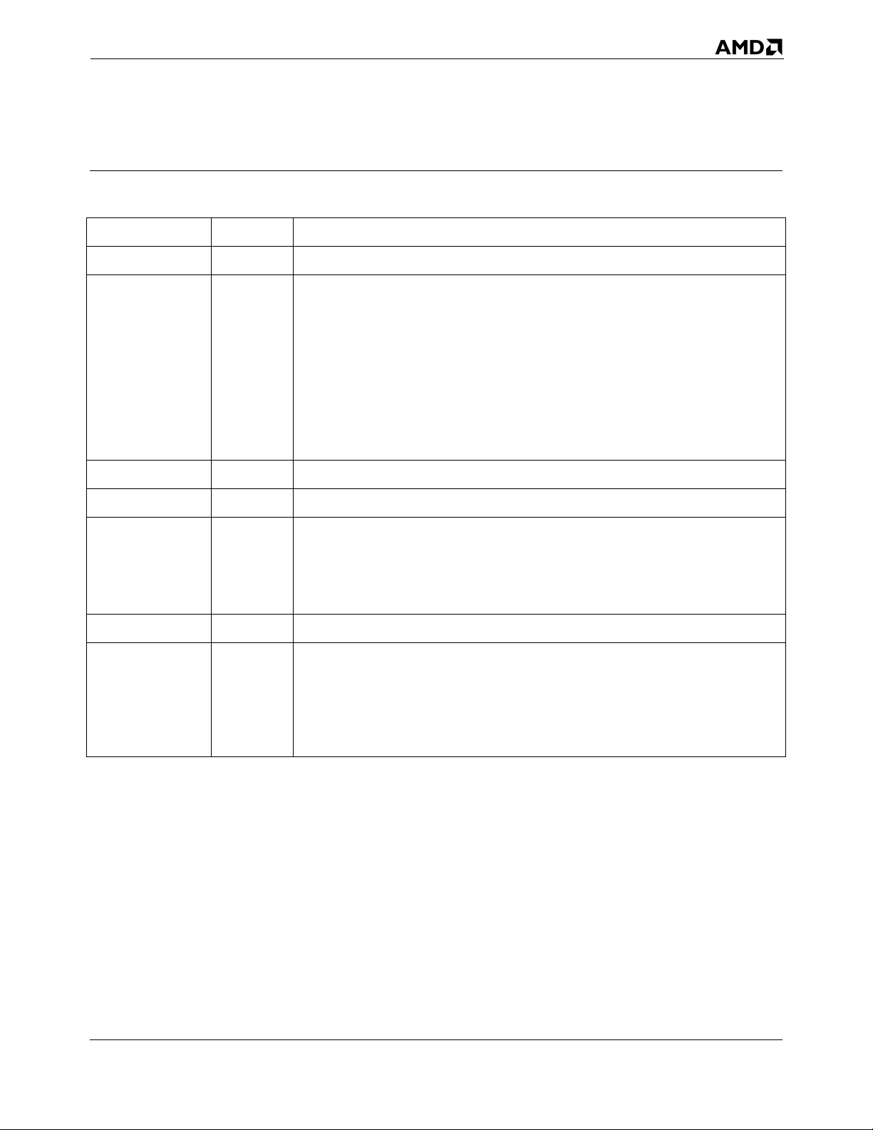
Revision History
Date Revision Description
September 2007 3.14 Incorporated minor clarifications and formatting changes.
Revised rFLAGS register table 3-5 on page 34.
Added “Cross-Modifying Code” on page 103.
Added “Feature Detection in a Virtualized Environment” on page 76.
Merged table of MXCSR register reset values into Figure 4-13 on page 118.
July 2007 3.13
September 2006 3.12 Incorporated minor clarifications and formatting changes.
Added “Misaligned Exception Mask (MM)” on page 120.
Revised indefinite-value encodings in table 4-7 on page 132 and table 6-10
on page 259.
Revised “Precision” on page 260.
Made minor editorial changes for purposes of clarification.
December 2005 3.11 Updated index entries.
Clarified “Self-Modifying Code” on page 98. Made several patches to index
references. Added general descriptions of SSE3 instructions to Chapter 4.
February 2005 3.10
September 2003 3.09 Corrected several factual errors.
September,
2002
3.07
Added description of the CMPXCHG16B instruction to Chapter 3. Corrected
minor typographical errors. Elaborated explanation of PREFETCHlevel
instructions.
Corrected minor organizational problems in sections dealing with ‘Prefetch’
instructions in Chapters 3, 4, and 5. Clarified the general description of the
operation of certain 128-bit media instructions in Chapter 1. Corrected a
factual error in the description of the FNINIT/FINIT instructions in Chapter 6.
Corrected operand descriptions for the CMOVcc instructions in Chapter 3.
Added Revision History. Corrected marketing denotations.
Revision History xv
Page 18
AMD64 Technology 24592—Rev. 3.14—September 2007
xvi Revision History
Page 19
24592—Rev. 3.14—September 2007 AMD64 Technology
Preface
About This Book
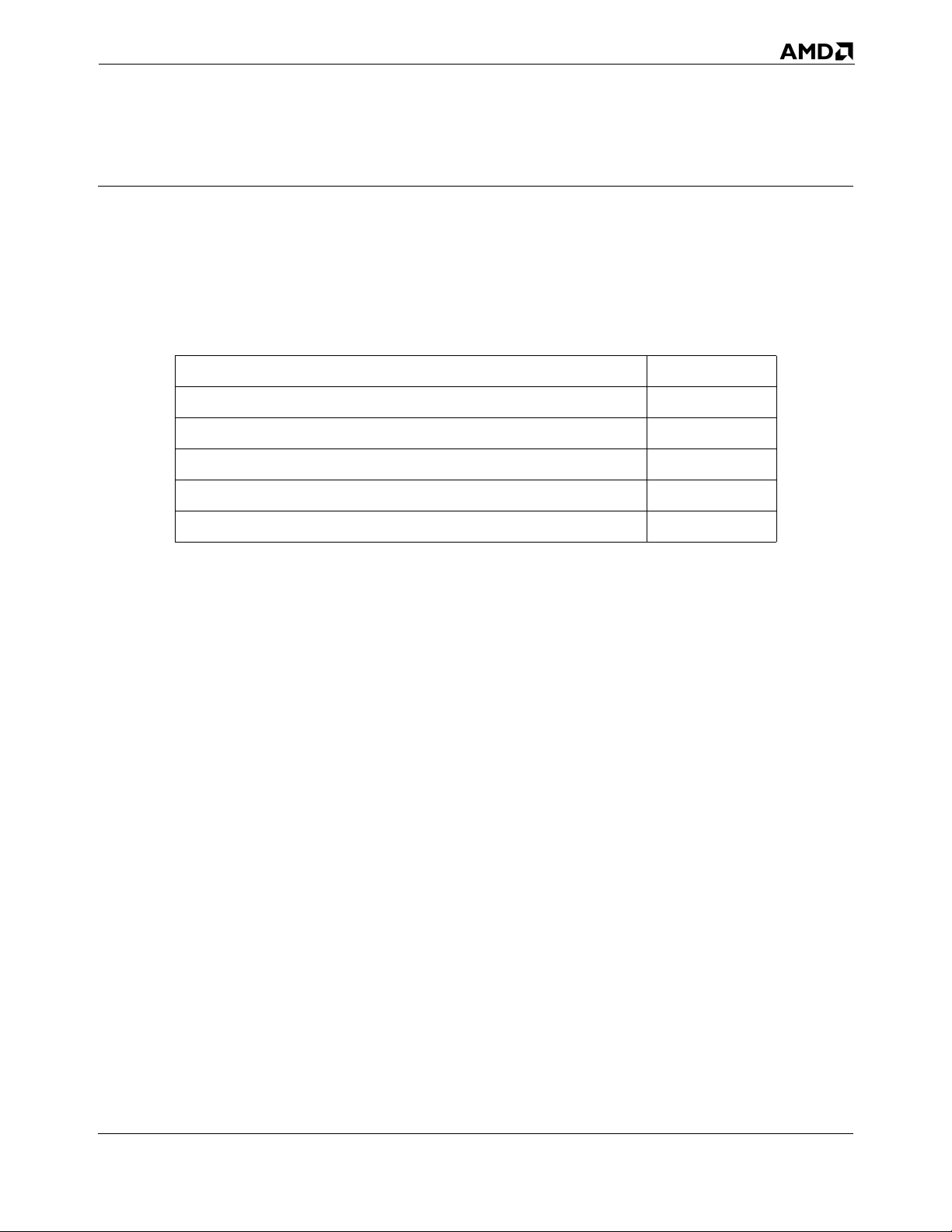
This book is part of a multivolume work entitled the AMD64 Architecture Pr ogrammer’s Manual. This
table lists each volume and its order number.
Title Order No.
Volume 1: Application Programming 24592
Volume 2: System Programming 24593
Volume 3: General-Purpose and System Instructions 24594
Volume 4: 128-Bit Media Instructions 26568
Volume 5: 64-Bit Media and x87 Floating-Point Instructions 26569
Audience
This volume (Volume 1) is intended for programmers writing application programs, compilers, or
assemblers. It assumes prior experience in microprocessor programming, although it does not assume
prior experience with the legacy x86 or AMD64 microprocessor architecture.
This volume describes the AMD64 architecture’s resources and functions that are accessible to
application software, including memory, registers, instructions, operands, I/O facilities, and
application-software aspects of control transfers (including interrupts and exceptions) and
performance optimization.
System-programming topics—including the use of instructions running at a current privilege level
(CPL) of 0 (most-privileged)—are described in Volume 2. Details about each instruction are described
in volumes 3, 4, and 5.
Organization
This volume begins with an overview of the architecture and its memory organization and is followed
by chapters that describe the four application-programming models available in the AMD64
architecture:
• General-Purpose Programming—This model uses the integer general-purpose registers (GPRs).
The chapter describing it also describes the basic application environment for exceptions, control
transfers, I/O, and memory optimization that applies to all other application-programming models.
Preface xvii
Page 20
AMD64 Technology 24592—Rev. 3.14—September 2007
• 128-bit Media Programming—This model uses the 128-bit XMM registers and supports integer
and floating-point operations on vector (packed) and scalar data types.
• 64-bit Media Programming—This model uses the 64-bit MMX™ registers and supports integer
and floating-point operations on vector (packed) and scalar data types.
• x87 Floating-Point Pr ogramming—This model uses the 80-bit x87 registers and supports floating-
point operations on scalar data types.
Definitions assumed throughout this volume are listed below. The index at the end of this volume
cross-references topics within the volume. For other topics relating to the AMD64 architecture, see the
tables of contents and indexes of the other volumes.
Definitions
Some of the following definitions assume a knowledge of the legacy x86 architecture. See “Related
Documents” on page xxviii for further information about the legacy x86 architecture.
Terms and Notation
1011b
A binary value—in this example, a 4-bit value.
F0EAh
A hexadecimal value—in this example a 2-byte value.
[1,2)
A range that includes the left-most value (in this case, 1) but excludes the right-most value (in this
case, 2).
7–4
A bit range, from bit 7 to 4, inclusive. The high-order bit is shown first.
128-bit media instructions
Instructions that use the 128-bit XMM registers. These are a combination of the SSE and SSE2
instruction sets.
64-bit media instructions
Instructions that use the 64-bit MMX registers. These are primarily a combination of MMX and
3DNow!™ instruction sets, with some additional instructions from the SSE and SSE2 instruction
sets.
16-bit mode
Legacy mode or compatibility mode in which a 16-bit address size is active. See legacy mode and
compatibility mode.
xviii Preface
Page 21
24592—Rev. 3.14—September 2007 AMD64 Technology
32-bit mode
Legacy mode or compatibility mode in which a 32-bit address size is active. See legacy mode and
compatibility mode.
64-bit mode
A submode of long mode. In 64-bit mode, the default address size is 64 bits and new features, such
as register extensions, are supported for system and application software.
#GP(0)
Notation indicating a general-protection exception (#GP) with error code of 0.
absolute
Said of a displacement that references the base of a code segment rather than an instruction pointer.
Contrast with relative.
ASID
Address space identifier.
biased exponent
The sum of a floating-point value’s exponent and a constant bias for a particular floating-point data
type. The bias makes the range of the biased exponent always positive, which allows reciprocation
without overflow.
byte
Eight bits.
clear
To write a bit value of 0. Compare set.
compatibility mode
A submode of long mode. In compatibility mode, the default address size is 32 bits, and legacy 16-
bit and 32-bit applications run without modification.
commit
To irreversibly write, in program order, an instruction’s result to software-visible storage, such as a
register (including flags), the data cache, an internal write buffer, or memory.
CPL
Current privilege level.
CR0–CR4
A register range, from register CR0 through CR4, inclusive, with the low-order register first.
CR0.PE = 1
Notation indicating that the PE bit of the CR0 register has a value of 1.
Preface xix
Page 22
AMD64 Technology 24592—Rev. 3.14—September 2007
direct
Referencing a memory location whose address is included in the instruction’s syntax as an
immediate operand. The address may be an absolute or relative address. Compare indirect.
dirty data
Data held in the processor’s caches or internal buffers that is more recent than the copy held in
main memory.
displacement
A signed value that is added to the base of a segment (absolute addressing) or an instruction pointer
(relative addressing). Same as offset.
doubleword
Two words, or four bytes, or 32 bits.
double quadword
Eight words, or 16 bytes, or 128 bits. Also called octword.
DS:rSI
The contents of a memory location whose segment address is in the DS register and whose offset
relative to that segment is in the rSI register.
EFER.LME = 0
Notation indicating that the LME bit of the EFER register has a value of 0.
effective address size
The address size for the current instruction after accounting for the default address size and any
address-size override prefix.
effective operand size
The operand size for the current instruction after accounting for the default operand size and any
operand-size override prefix.
element
See vector.
exception
An abnormal condition that occurs as the result of executing an instruction. The processor’s
response to an exception depends on the type of the exception. For all exceptions except 128-bit
media SIMD floating-point exceptions and x87 floating-point exceptions, control is transferred to
the handler (or service routine) for that exception, as defined by the exception’s vector. For
floating-point exceptions defined by the IEEE 754 standard, there are both masked and unmasked
responses. When unmasked, the exception handler is called, and when masked, a default response
is provided instead of calling the handler.
xx Preface
Page 23
24592—Rev. 3.14—September 2007 AMD64 Technology
FF /0
Notation indicating that FF is the first byte of an opcode, and a subopcode in the ModR/M byte has
a value of 0.
flush
An often ambiguous term meaning (1) writeback, if modified, and invalidate, as in “flush the cache
line,” or (2) invalidate, as in “flush the pipeline,” or (3) change a value, as in “flush to zero.”
GDT
Global descriptor table.
GIF
Global interrupt flag.
IDT
Interrupt descriptor table.
IGN
Ignore. Field is ignored.
indirect
Referencing a memory location whose address is in a register or other memory location. The
address may be an absolute or relative address. Compare direct.
IRB
The virtual-8086 mode interrupt-redirection bitmap.
IST
The long-mode interrupt-stack table.
IVT
The real-address mode interrupt-vector table.
LDT
Local descriptor table.
legacy x86
The legacy x86 architecture. See “Related Documents” on page xxviii for descriptions of the
legacy x86 architecture.
legacy mode
An operating mode of the AMD64 architecture in which existing 16-bit and 32-bit applications and
operating systems run without modification. A processor implementation of the AMD64
architecture can run in either long mode or legacy mode. Legacy mode has three submodes, real
mode, pr otected mode, and virtual-8086 mode.
Preface xxi
Page 24
AMD64 Technology 24592—Rev. 3.14—September 2007
long mode
An operating mode unique to the AMD64 architecture. A processor implementation of the
AMD64 architecture can run in either long mode or legacy mode. Long mode has two submodes,
64-bit mode and compatibility mode.
lsb
Least-significant bit.
LSB
Least-significant byte.
main memory
Physical memory, such as RAM and ROM (but not cache memory) that is installed in a particular
computer system.
mask
(1) A control bit that prevents the occurrence of a floating-point exception from invoking an
exception-handling routine. (2) A field of bits used for a control purpose.
MBZ
Must be zero. If software attempts to set an MBZ bit to 1, a general-protection exception (#GP)
occurs.
memory
Unless otherwise specified, main memory.
ModRM
A byte following an instruction opcode that specifies address calculation based on mode (Mod),
register (R), and memory (M) variables.
moffset
A 16, 32, or 64-bit offset that specifies a memory operand directly, without using a ModRM or SIB
byte.
msb
Most-significant bit.
MSB
Most-significant byte.
multimedia instructions
A combination of 128-bit media instructions and 64-bit media instructions.
octword
Same as double quadword.
xxii Preface
Page 25
24592—Rev. 3.14—September 2007 AMD64 Technology
offset
Same as displacement.
overflow
The condition in which a floating-point number is larger in magnitude than the largest, finite,
positive or negative number that can be represented in the data-type format being used.
packed
See vector.
PAE
Physical-address extensions.
physical memory
Actual memory, consisting of main memory and cache.
probe
A check for an address in a processor’s caches or internal buffers. External probes originate
outside the processor, and internal pr obes originate within the processor.
protected mode
A submode of legacy mode.
quadword
Four words, or eight bytes, or 64 bits.
RAZ
Read as zero (0), regardless of what is written.
real-addr ess mode
See real mode.
real mode
A short name for real-addr ess mode, a submode of legacy mode.
relative
Referencing with a displacement (also called offset) from an instruction pointer rather than the
base of a code segment. Contrast with absolute.
reserved
Fields marked as reserved may be used at some future time.
To preserve compatibility with future processors, reserved fields require special handling when
read or written by software.
Reserved fields may be further qualified as MBZ, RAZ, SBZ or IGN (see definitions).
Preface xxiii
Page 26
AMD64 Technology 24592—Rev. 3.14—September 2007
Software must not depend on the state of a reserved field, nor upon the ability of such fields to
return to a previously written state.
If a reserved field is not marked with one of the above qualifiers, software must not change the state
of that field; it must reload that field with the same values returned from a prior read.
REX
An instruction prefix that specifies a 64-bit operand size and provides access to additional
registers.
RIP-relative addr essing
Addressing relative to the 64-bit RIP instruction pointer.
scalar
An atomic value existing independently of any specification of location, direction, etc., as opposed
to vectors.
set
To write a bit value of 1. Compare clear.
SIB
A byte following an instruction opcode that specifies address calculation based on scale (S), index
(I), and base (B).
SIMD
Single instruction, multiple data. See vector.
SSE
Streaming SIMD extensions instruction set. See 128-bit media instructions and 64-bit media
instructions.
SSE2
Extensions to the SSE instruction set. See 128-bit media instructions and 64-bit media
instructions.
SSE3
Further extensions to the SSE instruction set. See 128-bit media instructions.
SSE4A
Further extensions to the SSE instruction set. See 128-bit media instructions.
sticky bit
A bit that is set or cleared by hardware and that remains in that state until explicitly changed by
software.
TOP
The x87 top-of-stack pointer.
xxiv Preface
Page 27
24592—Rev. 3.14—September 2007 AMD64 Technology
TSS
Task-state segment.
underflow
The condition in which a floating-point number is smaller in magnitude than the smallest nonzero,
positive or negative number that can be represented in the data-type format being used.
vector
(1) A set of integer or floating-point values, called elements, that are packed into a single operand.
Most of the 128-bit and 64-bit media instructions use vectors as operands. Vectors are also called
packed or SIMD (single-instruction multiple-data) operands.
(2) An index into an interrupt descriptor table (IDT), used to access exception handlers. Compare
exception.
virtual-8086 mode
A submode of legacy mode.
VMCB
Virtual machine control block.
VMM
Virtual machine monitor.
word
Two bytes, or 16 bits.
x86
See legacy x86.
Registers
In the following list of registers, the names are used to refer either to a given register or to the contents
of that register:
AH–DH
The high 8-bit AH, BH, CH, and DH registers. Compare AL–DL.
AL–DL
The low 8-bit AL, BL, CL, and DL registers. Compare AH–DH.
AL–r15B
The low 8-bit AL, BL, CL, DL, SIL, DIL, BPL, SPL, and R8B–R15B registers, available in 64-bit
mode.
BP
Base pointer register.
Preface xxv
Page 28
AMD64 Technology 24592—Rev. 3.14—September 2007
CRn
Control register number n.
CS
Code segment register.
eAX–eSP
The 16-bit AX, BX, CX, DX, DI, SI, BP, and SP registers or the 32-bit EAX, EBX, ECX, EDX,
EDI, ESI, EBP, and ESP registers. Compare rAX–rSP.
EFER
Extended features enable register.
eFLAGS
16-bit or 32-bit flags register. Compare rFLAGS.
EFLAGS
32-bit (extended) flags register.
eIP
16-bit or 32-bit instruction-pointer register. Compare rIP.
EIP
32-bit (extended) instruction-pointer register.
FLAGS
16-bit flags register.
GDTR
Global descriptor table register.
GPRs
General-purpose registers. For the 16-bit data size, these are AX, BX, CX, DX, DI, SI, BP, and SP.
For the 32-bit data size, these are EAX, EBX, ECX, EDX, EDI, ESI, EBP, and ESP. For the 64-bit
data size, these include RAX, RBX, RCX, RDX, RDI, RSI, RBP, RSP, and R8–R15.
IDTR
Interrupt descriptor table register.
IP
16-bit instruction-pointer register.
LDTR
Local descriptor table register.
xxvi Preface
Page 29
24592—Rev. 3.14—September 2007 AMD64 Technology
MSR
Model-specific register.
r8–r15
The 8-bit R8B–R15B registers, or the 16-bit R8W–R15W registers, or the 32-bit R8D–R15D
registers, or the 64-bit R8–R15 registers.
rAX–rSP
The 16-bit AX, BX, CX, DX, DI, SI, BP, and SP registers, or the 32-bit EAX, EBX, ECX, EDX,
EDI, ESI, EBP, and ESP registers, or the 64-bit RAX, RBX, RCX, RDX, RDI, RSI, RBP, and RSP
registers. Replace the placeholder r with nothing for 16-bit size, “E” for 32-bit size, or “R” for 64-
bit size.
RAX
64-bit version of the EAX register.
RBP
64-bit version of the EBP register.
RBX
64-bit version of the EBX register.
RCX
64-bit version of the ECX register.
RDI
64-bit version of the EDI register.
RDX
64-bit version of the EDX register.
rFLAGS
16-bit, 32-bit, or 64-bit flags register. Compare RFLAGS.
RFLAGS
64-bit flags register. Compare rFLAGS.
rIP
16-bit, 32-bit, or 64-bit instruction-pointer register. Compare RIP.
RIP
64-bit instruction-pointer register.
RSI
64-bit version of the ESI register.
Preface xxvii
Page 30
AMD64 Technology 24592—Rev. 3.14—September 2007
RSP
64-bit version of the ESP register.
SP
Stack pointer register.
SS
Stack segment register.
TPR
Task priority register (CR8), a new register introduced in the AMD64 architecture to speed
interrupt management.
TR
Task register.
Endian Order
The x86 and AMD64 architectures address memory using little-endian byte-ordering. Multibyte
values are stored with their least-significant byte at the lowest byte address, and they are illustrated
with their least significant byte at the right side. Strings are illustrated in reverse order, because the
addresses of their bytes increase from right to left.
Related Documents
• Peter Abel, IBM PC Assembly Language and Pr ogramming , Prentice-Hall, Englewood Cliffs, NJ,
1995.
• Rakesh Agarwal, 80x86 Architecture & Programming: Volume II, Prentice-Hall, Englewood
Cliffs, NJ, 1991.
• AMD data sheets and application notes for particular hardware implementations of the AMD64
architecture.
®
• AMD, AMD-K6
• AMD, 3DNow!™ Technology Manual, Sunnyvale, CA, 2000.
• AMD, AMD Extensions to the 3DNow!™ and MMX™ Instruction Sets, Sunnyvale, CA, 2000.
• Don Anderson and Tom Shanley, Pentium® Processor System Ar chitecture, Addison-Wesley, New
York, 1995.
• Nabajyoti Barkakati and Randall Hyde, Microsoft Macr o Assembler Bible, Sams, Carmel, Indiana,
1992.
MMX™ Enhanced Pr ocessor Multimedia Technology, Sunnyvale, CA, 2000.
• Barry B. Brey, 8086/8088, 80286, 80386, and 80486 Assembly Language Programming,
Macmillan Publishing Co., New York, 1994.
• Barry B. Brey, Programming the 80286, 80386, 80486, and Pentium Based Personal Computer,
Prentice-Hall, Englewood Cliffs, NJ, 1995.
xxviii Preface
Page 31
24592—Rev. 3.14—September 2007 AMD64 Technology
• Ralf Brown and Jim Kyle, PC Interrupts, Addison-Wesley, New York, 1994.
• Penn Brumm and Don Brumm, 80386/80486 Assembly Language Programming, Windcrest
McGraw-Hill, 1993.
• Geoff Chappell, DOS Internals, Addison-Wesley, New York, 1994.
• Chips and Technologies, Inc. Super386 DX Programmer’s Reference Manual, Chips and
Technologies, Inc., San Jose, 1992.
• John Crawford and Patrick Gelsinger, Programming the 80386, Sybex, San Francisco, 1987.
• Cyrix Corporation, 5x86 Processor BIOS Writer's Guide, Cyrix Corporation, Richardson, TX,
1995.
• Cyrix Corporation, M1 Pr ocessor Data Book, Cyrix Corporation, Richardson, TX, 1996.
• Cyrix Corporation, MX Pr ocessor MMX Extension Opcode Table, Cyrix Corporation, Richardson,
TX, 1996.
• Cyrix Corporation, MX Pr ocessor Data Book, Cyrix Corporation, Richardson, TX, 1997.
• Ray Duncan, Extending DOS: A Programmer's Guide to Protected-Mode DOS, Addison Wesley,
NY, 1991.
• William B. Giles, Assembly Language Programming for the Intel 80xxx Family, Macmillan, New
York, 1991.
• Frank van Gilluwe, The Undocumented PC, Addison-Wesley, New York, 1994.
• John L. Hennessy and David A. Patterson, Computer Architecture, Morgan Kaufmann Publishers,
San Mateo, CA, 1996.
• Thom Hogan, The Pr ogrammer’s PC Sourcebook, Microsoft Press, Redmond, WA, 1991.
• Hal Katircioglu, Inside the 486, Pentium®, and Pentium Pro, Peer-to-Peer Communications,
Menlo Park, CA, 1997.
• IBM Corporation, 486SLC Microprocessor Data Sheet, IBM Corporation, Essex Junction, VT,
1993.
• IBM Corporation, 486SLC2 Microprocessor Data Sheet, IBM Corporation, Essex Junction, VT,
1993.
• IBM Corporation, 80486DX2 Processor Floating Point Instructions, IBM Corporation, Essex
Junction, VT, 1995.
• IBM Corporation, 80486DX2 Processor BIOS Writer's Guide, IBM Corporation, Essex Junction,
VT, 1995.
• IBM Corporation, Blue Lightning 486DX2 Data Book, IBM Corporation, Essex Junction, VT,
1994.
• Institute of Electrical and Electronics Engineers, IEEE Standard for Binary Floating-Point
Arithmetic, ANSI/IEEE Std 754-1985.
• Institute of Electrical and Electronics Engineers, IEEE Standard for Radix-Independent Floating-
Point Arithmetic, ANSI/IEEE Std 854-1987.
Preface xxix
Page 32
AMD64 Technology 24592—Rev. 3.14—September 2007
• Muhammad Ali Mazidi and Janice Gillispie Mazidi, 80X86 IBM PC and Compatible Computers,
Prentice-Hall, Englewood Cliffs, NJ, 1997.
• Hans-Peter Messmer, The Indispensable Pentium Book, Addison-Wesley, New York, 1995.
• Karen Miller, An Assembly Language Introduction to Computer Architecture: Using the Intel
Pentium
®
, Oxford University Press, New York, 1999.
• Stephen Morse, Eric Isaacson, and Douglas Albert, The 80386/387 Architecture, John Wiley &
Sons, New York, 1987.
• NexGen Inc., Nx586 Pr ocessor Data Book, NexGen Inc., Milpitas, CA, 1993.
• NexGen Inc., Nx686 Pr ocessor Data Book, NexGen Inc., Milpitas, CA, 1994.
• Bipin Patwardhan, Introduction to the Streaming SIMD Extensions in the Pentium® III,
www.x86.org/articles/sse_pt1/ simd1.htm, June, 2000.
• Peter Norton, Peter Aitken, and Richard Wilton, PC Programmer’s Bible, Microsoft
®
Press,
Redmond, WA, 1993.
• PharLap 386|ASM Refer ence Manual, Pharlap, Cambridge MA, 1993.
• PharLap TNT DOS-Extender Refer ence Manual, Pharlap, Cambridge MA, 1995.
• Sen-Cuo Ro and Sheau-Chuen Her, i386/i486 Advanced Programming, Van Nostrand Reinhold,
New York, 1993.
• Jeffrey P. Royer, Introduction to Protected Mode Programming, course materials for an onsite
class, 1992.
• Tom Sha n ley, Protected Mode System Architectur e, Addison Wesley, NY, 1996.
• SGS-Thomson Corporation, 80486DX Processor SMM Programming Manual, SGS-Thomson
Corporation, 1995.
• Walter A. Triebel, The 80386DX Microprocessor, Prentice-Hall, Englewood Cliffs, NJ, 1992.
• John Wharton, The Complete x86, MicroDesign Resources, Sebastopol, California, 1994.
• Web sites and newsgroups:
- www.amd.com
- news.comp.arch
- news.comp.lang.asm.x86
- news.intel.microprocessors
- news.microsoft
xxx Preface
Page 33
24592—Rev. 3.14—September 2007 AMD64 Technology
1 Overview of the AMD64 Architecture
1.1 Introduction
The AMD64 architecture is a simple yet powerful 64-bit, backward-compatible extension of the
industry-standard (legacy) x86 architecture. It adds 64-bit addressing and expands register resources to
support higher performance for recompiled 64-bit programs, while supporting legacy 16-bit and 32-bit
applications and operating systems without modification or recompilation. It is the architectural basis
on which new processors can provide seamless, high-performance support for both the vast body of
existing software and 64-bit software required for higher-performance applications.
The need for a 64-bit x86 architecture is driven by applications that address large amounts of virtual
and physical memory, such as high-performance servers, database management systems, and CAD
tools. These applications benefit from both 64-bit addresses and an increased number of registers. The
small number of registers available in the legacy x86 architecture limits performance in computationintensive applications. Increasing the number of registers provides a performance boost to many such
applications.
1.1.1 AMD64 Features
The AMD64 architecture introduces these features:
• Register Extensions (see Figur e 1-1 on page 2):
- 8 additional general-purpose registers (GPRs).
- All 16 GPRs are 64 bits wide.
- 8 128-bit XMM registers.
- Uniform byte-register addressing for all GPRs.
- An instruction prefix (REX) accesses the extended registers.
• Long Mode (see Table 1-1 on page 2):
- Up to 64 bits of virtual address.
- 64-bit instruction pointer (RIP).
- Instruction-pointer-relative data-addressing mode.
- Flat address space.
Overview of the AMD64 Architecture 1
Page 34
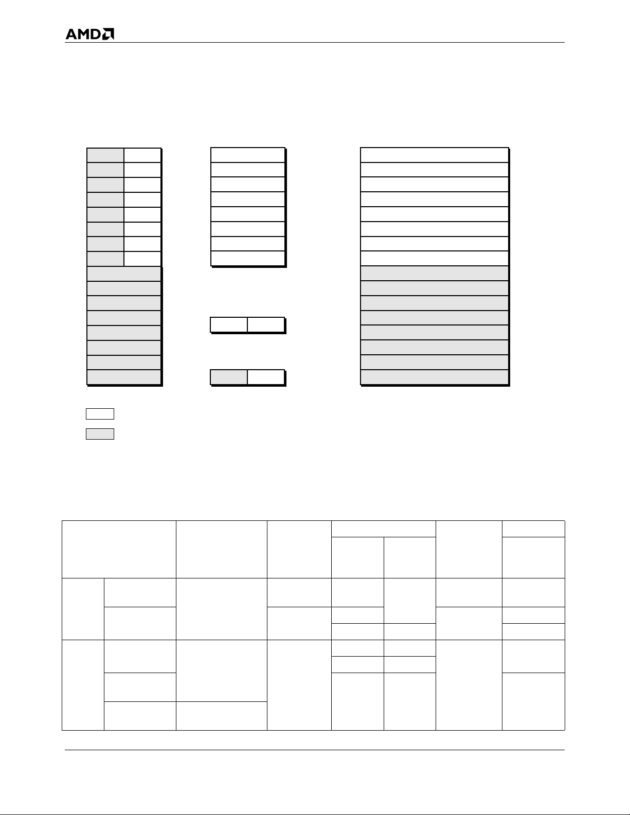
AMD64 Technology 24592—Rev. 3.14—September 2007
General-Purpose
Registers (GPRs)
64-Bit Media and
Floating-Point Registers
RAX
RBX
RCX
RDX
RBP
RSI
RDI
RSP
R8
63 0
R9
R10
R11
R12
R13
R14
R15
63 0 63 0
Legacy x86 registers, supported in all modes Application-programming registers also include the
Register extensions, supported in 64-bit mode
Flags Register
0 RFLAGS
EFLAGS
63 0
Instruction Pointer
EIP
128-Bit Media
Registers
MMX0/FPR0
MMX1/FPR1
MMX2/FPR2
MMX3/FPR3
MMX4/FPR4
MMX5/FPR5
MMX6/FPR6
MMX7/FPR7
RIP
127 0
128-bit media control-and-status register and the
x87 tag-word, control-word, and status-word registers
XMM0
XMM1
XMM2
XMM3
XMM4
XMM5
XMM6
XMM7
XMM8
XMM9
XMM10
XMM11
XMM12
XMM13
XMM14
XMM15
513-101.eps
Figure 1-1. Application-Programming Register Set
Table 1-1. Operating Modes
Operating Mode
64-Bit
Long
Mode
Mode
Compatibility
Mode
Protected
Mode
Legacy
Mode
Virtual-8086
Mode
Real
Mode
Operating
System Required
64-bit OS
Legacy 32-bit OS
Legacy 16-bit OS
Application
Recompile
Required
yes 64
no
no
Defaults
Address
Size
(bits)
Operand
Size
(bits)
32
32
16 16 16
Register
Extensions
yes 64
no
32 32
16 16
no
16 16 16
Typical
GPR
Width (bits)
32
32
2 Overview of the AMD64 Architecture
Page 35
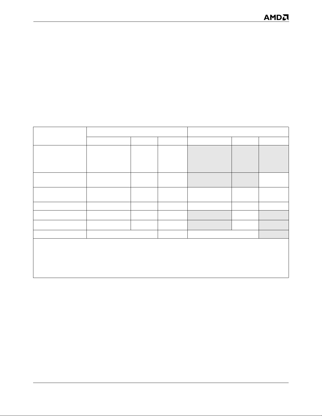
24592—Rev. 3.14—September 2007 AMD64 Technology
1.1.2 Registers
Table 1-2 compares the register and stack resources available to application software, by operating
mode. The left set of columns shows the legacy x86 resources, which are available in the AMD64
architecture’s legacy and compatibility modes. The right set of columns shows the comparable
resources in 64-bit mode. Gray shading indicates differences between the modes. These register
differences (not including stack-width difference) represent the register extensions shown in
Figure 1-1.
Table 1-2. Application Registers and Stack, by Operating Mode
Register
or Stack
General-Purpose
Registers (GPRs)
128-Bit XMM
Registers
64-Bit MMX
Registers
x87 Registers FPR0–FPR7
Instruction Pointer
2
Flags
Stack — 16 or 32 —
Note:
1. Gray-shaded entries indicate differences between the modes. These differences (except stack-width difference) are
the AMD64 architecture’s register extensions.
2. This list of GPRs shows only the 32-bit registers. The 16-bit and 8-bit mappings of the 32-bit registers are also
accessible, as described in “Registers” on page 23.
3. The MMX0–MMX7 registers are mapped onto the FPR0–FPR7 physical registers, as shown in Figure 1-1. The x87
stack registers, ST(0)–ST(7), are the logical mappings of the FPR0–FPR7 physical registers.
2
2
Legacy and Compatibility Modes
Name Number Size (bits) Name Number Size (bits)
EAX, EBX, ECX,
EDX, EBP, ESI,
EDI, ESP
XMM0–XMM7 8 128
MMX0–MMX7
EIP 1 32 RIP 1 64
EFLAGS 1 32 RFLAGS 1 64
3
3
832
8 64 MMX0–MMX7
8 80 FPR0–FPR7
RAX, RBX, RCX,
RDX, RBP, RSI,
RDI, RSP,
R8–R15
XMM0–XMM15 16 128
64-Bit Mode
3
3
1
16 64
864
880
64
As Table 1-2 shows, the legacy x86 architecture (called legacy mode in the AMD64 architecture)
supports eight GPRs. In reality, however, the general use of at least four registers (EBP, ESI, EDI, and
ESP) is compromised because they serve special purposes when executing many instructions. The
AMD64 architecture’s addition of eight GPRs—and the increased width of these registers from 32 bits
to 64 bits—allows compilers to substantially improve software performance. Compilers have more
flexibility in using registers to hold variables. Compilers can also minimize memory traffic—and thus
boost performance—by localizing work within the GPRs.
1.1.3 Instruction Set
The AMD64 architecture supports the full legacy x86 instruction set, with additional instructions to
support long mode (see Table 1-1 on page 2 for a summary of operating modes). The applicationprogramming instructions are organized into three subsets, as follows:
Overview of the AMD64 Architecture 3
Page 36
AMD64 Technology 24592—Rev. 3.14—September 2007
• General-Purpose Instructions—These are the basic x86 integer instructions used in virtually all
programs. Most of these instructions load, store, or operate on data located in the general-purpose
registers (GPRs) or memory. Some of the instructions alter sequential program flow by branching
to other program locations.
• 128-Bit Media Instructions—These are the str eaming SIMD extension (SSE, SSE2, SSE3,
SSE4A) instructions that load, store, or operate on data located primarily in the 128-bit XMM
registers. They perform integer and floating-point operations on vector (packed) and scalar data
types. Because the vector instructions can independently and simultaneously perform a single
operation on multiple sets of data, they are called single-instruction, multiple-data (SIMD)
instructions. They are useful for high-performance media and scientific applications that operate
on blocks of data.
• 64-Bit Media Instructions—These are the multimedia extension (MMX™ technology) and AMD
3DNow!™ technology instructions. These instructions load, store, or operate on data located
primarily in the 64-bit MMX registers. Like their 128-bit counterparts, described above, they
perform integer and floating-point operations on vector (packed) and scalar data types. Thus, they
are also SIMD instructions and are useful in media applications that operate on blocks of data.
AMD no longer recommends the use of 3DNow! instructions, which have been superceded by
their more efficient 128-bit media counterparts. Relevant recommendations are provided in
Chapter 5, “64-Bit Media Programming” on page 193, and in the AMD64 Programmer’s Manual
Volume 4: 64-Bit Media and x87 Floating-Point Instructions.
• x87 Floating-Point Instructions—These are the floating-point instructions used in legacy x87
applications. They load, store, or operate on data located in the x87 registers.
Some of these application-programming instructions bridge two or more of the above subsets. For
example, there are instructions that move data between the general-purpose registers and the XMM or
MMX registers, and many of the integer vector (packed) instructions can operate on either XMM or
MMX registers, although not simultaneously. If instructions bridge two or more subsets, their
descriptions are repeated in all subsets to which they apply.
1.1.4 Media Instructions
Media applications—such as image processing, music synthesis, speech recognition, full-motion
video, and 3D graphics rendering—share certain characteristics:
• They process large amounts of data.
• They often perform the same sequence of operations repeatedly across the data.
• The data are often represented as small quantities, such as 8 bits for pixel values, 16 bits for audio
samples, and 32 bits for object coordinates in floating-point format.
The 128-bit and 64-bit media instructions are designed to accelerate these applications. The
instructions use a form of vector (or packed) parallel processing known as single-instruction, multiple
data (SIMD) processing. This vector technology has the following characteristics:
4 Overview of the AMD64 Architecture
Page 37
24592—Rev. 3.14—September 2007 AMD64 Technology
• A single register can hold multiple independent pieces of data. For example, a single 128-bit XMM
register can hold 16 8-bit integer data elements, or four 32-bit single-precision floating-point data
elements.
• The vector instructions can operate on all data elements in a register, independently and
simultaneously. For example, a PADDB instruction operating on byte elements of two vector
operands in 128-bit XMM registers performs 16 simultaneous additions and returns 16
independent results in a single operation.
128-bit and 64-bit media instructions take SIMD vector technology a step further by including special
instructions that perform operations commonly found in media applications. For example, a graphics
application that adds the brightness values of two pixels must prevent the add operation from wrapping
around to a small value if the result overflows the destination register, because an overflow result can
produce unexpected effects such as a dark pixel where a bright one is expected. The 128-bit and 64-bit
media instructions include saturating-arithmetic instructions to simplify this type of operation. A
result that otherwise would wrap around due to overflow or underflow is instead forced to saturate at
the largest or smallest value that can be represented in the destination register.
1.1.5 Floating-Point Instructions
The AMD64 architecture provides three floating-point instruction subsets, using three distinct register
sets:
• 128-Bit Media Instructions support 32-bit single-precision and 64-bit double-precision floating-
point operations, in addition to integer operations. Operations on both vector data and scalar data
are supported, with a dedicated floating-point exception-reporting mechanism. These floatingpoint operations comply with the IEEE-754 standard.
• 64-Bit Media Instructions (the subset of 3DNow! technology instructions) support single-
precision floating-point operations. Operations on both vector data and scalar data are supported,
but these instructions do not support floating-point exception reporting.
• x87 Floating-Point Instructions support single-precision, double-precision, and 80-bit extended-
precision floating-point operations. Only scalar data are supported, with a dedicated floating-point
exception-reporting mechanism. The x87 floating-point instructions contain special instructions
for performing trigonometric and logarithmic transcendental operations. The single-precision and
double-precision floating-point operations comply with the IEEE-754 standard.
Maximum floating-point performance can be achieved using the 128-bit media instructions. One of
these vector instructions can support up to four single-precision (or two double-precision) operations
in parallel. In 64-bit mode, the AMD64 architecture doubles the number of legacy XMM registers
from 8 to 16.
Applications gain additional benefits using the 64-bit media and x87 instructions. The separate register
sets supported by these instructions relieve pressure on the XMM registers available to the 128-bit
media instructions. This provides application programs with three distinct sets of floating-point
registers. In addition, certain high-end implementations of the AMD64 architecture may support 128bit media, 64-bit media, and x87 instructions with separate execution units.
Overview of the AMD64 Architecture 5
Page 38
AMD64 Technology 24592—Rev. 3.14—September 2007
1.2 Modes of Operation
Table 1-1 on page 2 summarizes the modes of operation supported by the AMD64 architecture. In
most cases, the default address and operand sizes can be overridden with instruction prefixes. The
register extensions shown in the second-from-right column of Table 1-1 are those illustrated in
Figure 1-1 on page 2.
1.2.1 Long Mode
Long mode is an extension of legacy protected mode. Long mode consists of two submodes: 64-bit
mode and compatibility mode. 64-bit mode supports all of the features and register extensions of the
AMD64 architecture. Compatibility mode supports binary compatibility with existing 16-bit and 32bit applications. Long mode does not support legacy real mode or legacy virtual-8086 mode, and it
does not support hardware task switching.
Throughout this document, references to long mode refer to both 64-bit mode and compatibility mode.
If a function is specific to either of these submodes, then the name of the specific submode is used
instead of the name long mode.
1.2.2 64-Bit Mode
64-bit mode—a submode of long mode—supports the full range of 64-bit virtual-addressing and
register-extension features. This mode is enabled by the operating system on an individual codesegment basis. Because 64-bit mode supports a 64-bit virtual-address space, it requires a 64-bit
operating system and tool chain. Existing application binaries can run without recompilation in
compatibility mode, under an operating system that runs in 64-bit mode, or the applications can also be
recompiled to run in 64-bit mode.
Addressing features include a 64-bit instruction pointer (RIP) and an RIP-relative data-addressing
mode. This mode accommodates modern operating systems by supporting only a flat address space,
with single code, data, and stack space.
Register Extensions. 64-bit mode implements register extensions through a group of instruction
prefixes, called REX prefixes. These extensions add eight GPRs (R8–R15), widen all GPRs to 64 bits,
and add eight 128-bit XMM registers (XMM8–XMM15).
The REX instruction prefixes also provide a byte-register capability that makes the low byte of any of
the sixteen GPRs available for byte operations. This results in a uniform set of byte, word, doubleword,
and quadword registers that is better suited to compiler register-allocation.
64-Bit Addresses and Operands. In 64-bit mode, the default virtual-address size is 64 bits
(implementations can have fewer). The default operand size for most instructions is 32 bits. For most
instructions, these defaults can be overridden on an instruction-by-instruction basis using instruction
prefixes. REX prefixes specify the 64-bit operand size and register extensions.
RIP-Relative Data Addressing. 64-bit mode supports data addressing relative to the 64-bit
instruction pointer (RIP). The legacy x86 architecture supports IP-relative addressing only in control-
6 Overview of the AMD64 Architecture
Page 39
24592—Rev. 3.14—September 2007 AMD64 Technology
transfer instructions. RIP-relative addressing improves the efficiency of position-independent code
and code that addresses global data.
Opcodes. A few instruction opcodes and prefix bytes are redefined to allow register extensions and
64-bit addressing. These differences are described in “General-Purpose Instructions in 64-Bit Mode”
in Volume 3 and “Differences Between Long Mode and Legacy Mode” in Volume 3.
1.2.3 Compatibility Mode
Compatibility mode—the second submode of long mode—allows 64-bit operating systems to run
existing 16-bit and 32-bit x86 applications. These legacy applications run in compatibility mode
without recompilation.
Applications running in compatibility mode use 32-bit or 16-bit addressing and can access the first
4GB of virtual-address space. Legacy x86 instruction prefixes toggle between 16-bit and 32-bit
address and operand sizes.
As with 64-bit mode, compatibility mode is enabled by the operating system on an individual codesegment basis. Unlike 64-bit mode, however, x86 segmentation functions the same as in the legacy x86
architecture, using 16-bit or 32-bit protected-mode semantics. From the application viewpoint,
compatibility mode looks like the legacy x86 protected-mode environment. From the operatingsystem viewpoint, however, address translation, interrupt and exception handling, and system data
structures use the 64-bit long-mode mechanisms.
1.2.4 Legacy Mode
Legacy mode preserves binary compatibility not only with existing 16-bit and 32-bit applications but
also with existing 16-bit and 32-bit operating systems. Legacy mode consists of the following three
submodes:
• Pr otected Mode—Protected mode supports 16-bit and 32-bit programs with memory
segmentation, optional paging, and privilege-checking. Programs running in protected mode can
access up to 4GB of memory space.
• Virtual-8086 Mode—Virtual-8086 mode supports 16-bit real-mode programs running as tasks
under protected mode. It uses a simple form of memory segmentation, optional paging, and limited
protection-checking. Programs running in virtual-8086 mode can access up to 1MB of memory
space.
• Real Mode—Real mode supports 16-bit programs using simple register-based memory
segmentation. It does not support paging or protection-checking. Programs running in real mode
can access up to 1MB of memory space.
Legacy mode is compatible with existing 32-bit processor implementations of the x86 architecture.
Processors that implement the AMD64 architecture boot in legacy real mode, just like processors that
implement the legacy x86 architecture.
Overview of the AMD64 Architecture 7
Page 40
AMD64 Technology 24592—Rev. 3.14—September 2007
Throughout this document, references to legacy mode refer to all three submodes—protected mode,
virtual-8086 mode, and real mode. If a function is specific to either of these submodes, then the name
of the specific submode is used instead of the name legacy mode.
8 Overview of the AMD64 Architecture
Page 41
24592—Rev. 3.14—September 2007 AMD64 Technology
2 Memory Model
This chapter describes the memory characteristics that apply to application software in the various
operating modes of the AMD64 architecture. These characteristics apply to all instructions in the
architecture. Several additional system-level details about memory and cache management are
described in Volume 2.
2.1 Memory Organization
2.1.1 Virtual Memory
Virtual memory consists of the entire address space available to programs. It is a large linear-address
space that is translated by a combination of hardware and operating-system software to a smaller
physical-address space, parts of which are located in memory and parts on disk or other external
storage media.
Figure 2-1 on page 10 shows how the virtual-memory space is treated in the two submodes of long
mode:
• 64-bit mode—This mode uses a flat segmentation model of virtual memory. The 64-bit virtual-
memory space is treated as a single, flat (unsegmented) address space. Program addresses access
locations that can be anywhere in the linear 64-bit address space. The operating system can use
separate selectors for code, stack, and data segments for memory-protection purposes, but the base
address of all these segments is always 0. (For an exception to this general rule, see “FS and GS as
Base of Address Calculation” on page 17.)
• Compatibility mode—This mode uses a protected, multi-segment model of virtual memory, just as
in legacy protected mode. The 32-bit virtual-memory space is treated as a segmented set of address
spaces for code, stack, and data segments, each with its own base address and protection
parameters. A segmented space is specified by adding a segment selector to an address.
Memory Model 9
Page 42
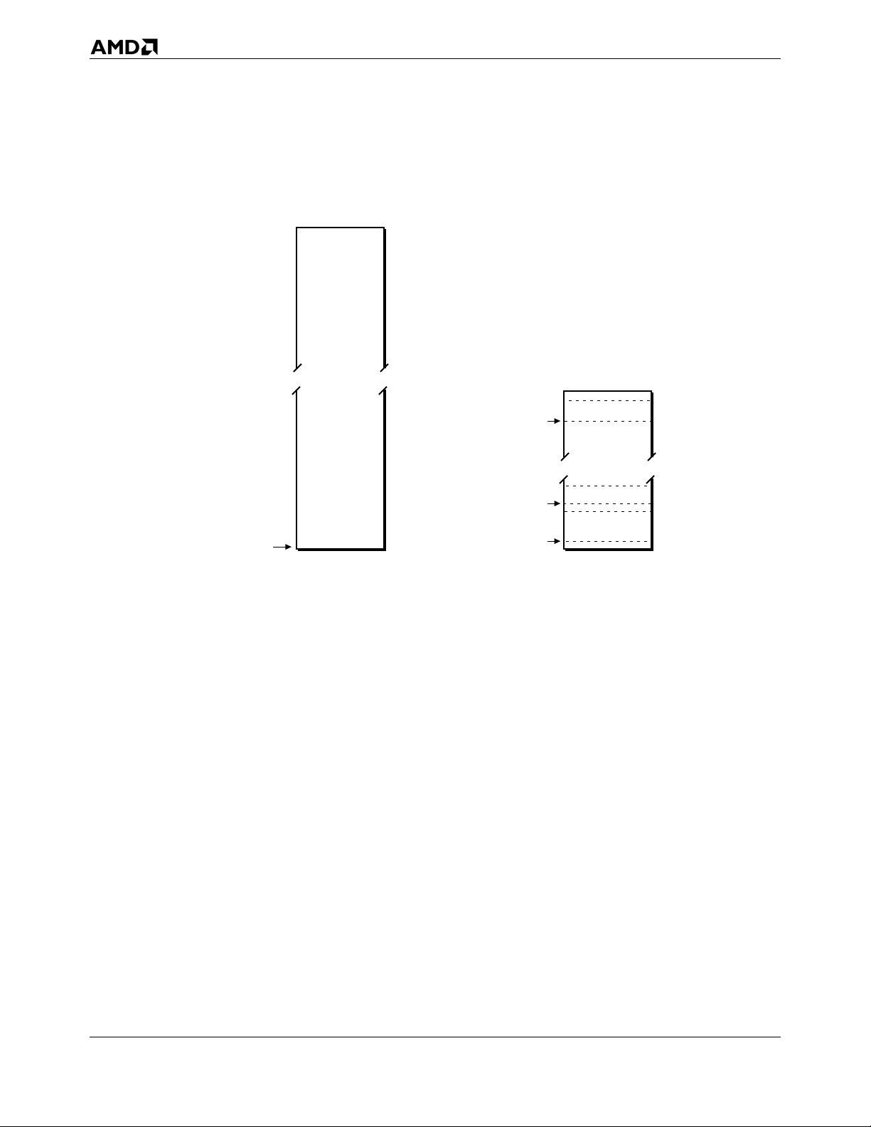
AMD64 Technology 24592—Rev. 3.14—September 2007
64-Bit Mode
(Flat Segmentation Model)
264 - 1
Legacy and Compatibility Mode
(Multi-Segment Model)
232 - 1
Code Segment (CS) Base
code
stack
data
0
513-107.eps
Base Address for
All Segments
Stack Segment (SS) Base
Data Segment (DS) Base
0
Figure 2-1. Virtual-Memory Segmentation
Operating systems have used segmented memory as a method to isolate programs from the data they
used, in an effort to increase the reliability of systems running multiple programs simultaneously.
However, most modern operating systems do not use the segmentation features available in the legacy
x86 architecture. Instead, these operating systems handle segmentation functions entirely in software.
For this reason, the AMD64 architecture dispenses with most of the legacy segmentation functions in
64-bit mode. This allows 64-bit operating systems to be coded more simply, and it supports more
efficient management of multi-tasking environments than is possible in the legacy x86 architecture.
2.1.2 Segment Registers
Segment registers hold the selectors used to access memory segments. Figure 2-2 on page 11 shows
the application-visible portion of the segment registers. In legacy and compatibility modes, all segment
registers are accessible to software. In 64-bit mode, only the CS, FS, and GS segments are recognized
by the processor, and software can use the FS and GS segment-base registers as base registers for
address calculation, as described in “FS and GS as Base of Address Calculation” on page 17. For
references to the DS, ES, or SS segments in 64-bit mode, the processor assumes that the base for each
of these segments is zero, neither their segment limit nor attributes are checked, and the processor
simply checks that all such addresses are in canonical form, as described in “64-Bit Canonical
Addresses” on page 15.
10 Memory Model
Page 43
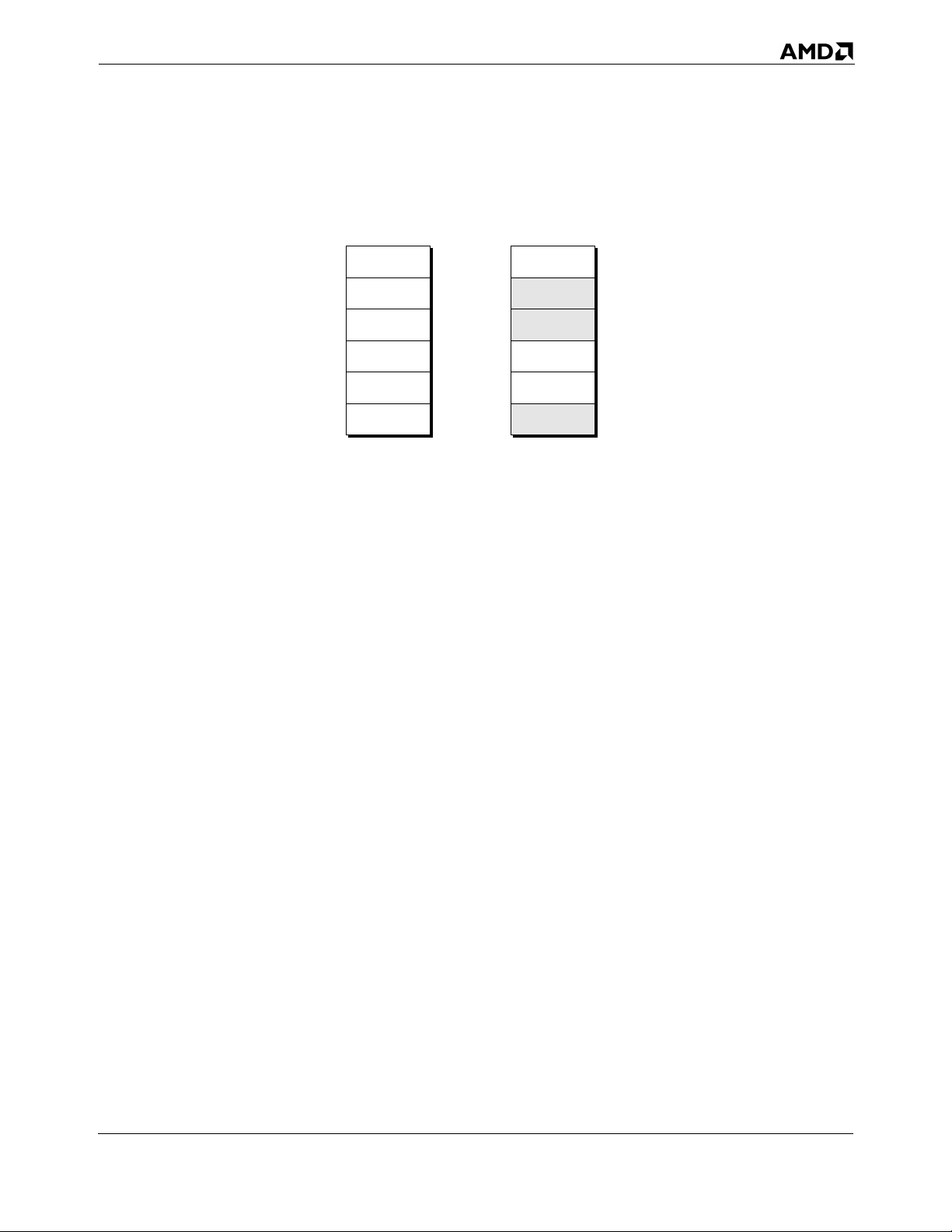
24592—Rev. 3.14—September 2007 AMD64 Technology
Legacy Mode and
Compatibility Mode
CS
DS
ES
FS
GS
SS
15 0
64-Bit
Mode
CS
(Attributes only)
ignored
ignored
FS
(Base only)
GS
(Base only)
ignored
15 0
513-312.eps
Figure 2-2. Segment Registers
For details on segmentation and the segment registers, see “Segmented Virtual Memory” in Volume 2.
2.1.3 Physical Memory
Physical memory is the installed memory (excluding cache memory) in a particular computer system
that can be accessed through the processor’s bus interface. The maximum size of the physical memory
space is determined by the number of address bits on the bus interface. In a virtual-memory system, the
large virtual-address space (also called linear-address space) is translated to a smaller physical-
address space by a combination of segmentation and paging hardware and software.
Segmentation is illustrated in Figure 2-1 on page 10. Paging is a mechanism for translating linear
(virtual) addresses into fixed-size blocks called pages, which the operating system can move, as
needed, between memory and external storage media (typically disk). The AMD64 architecture
supports an expanded version of the legacy x86 paging mechanism, one that is able to translate the full
64-bit virtual-address space into the physical-address space supported by the particular
implementation.
2.1.4 Memory Management
Memory management strategies translate addresses generated by programs into addresses in physical
memory using segmentation and/or paging. Memory management is not visible to application
programs. It is handled by the operating system and processor hardware. The following description
gives a very brief overview of these functions. Details are given in “System-Management Instructions”
in Volume 2.
Memory Model 11
Page 44
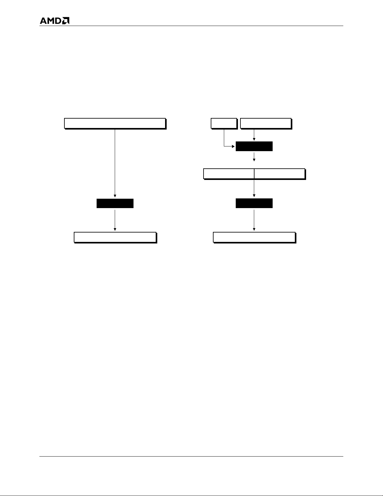
AMD64 Technology 24592—Rev. 3.14—September 2007
Long-Mode Memory Management. Figure 2-3 shows the flow, from top to bottom, of memory
management functions performed in the two submodes of long mode.
64-Bit Mode
63 0
Virtual (Linear) Address
Paging
051
Physical Address
Figure 2-3. Long-Mode Memory Management
Compatibility Mode
031015
Effective AddressSelector
Segmentation
0313263
Virtual Address0
Paging
051
Physical Address
513-184.eps
In 64-bit mode, programs generate virtual (linear) addresses that can be up to 64 bits in size. The
virtual addresses are passed to the long-mode paging function, which generates physical addresses that
can be up to 52 bits in size. (Specific implementations of the architecture can support smaller virtualaddress and physical-address sizes.)
In compatibility mode, legacy 16-bit and 32-bit applications run using legacy x86 protected-mode
segmentation semantics. The 16-bit or 32-bit effective addresses generated by programs are combined
with their segments to produce 32-bit virtual (linear) addresses that are zero-extended to a maximum
of 64 bits. The paging that follows is the same long-mode paging function used in 64-bit mode. It
translates the virtual addresses into physical addresses. The combination of segment selector and
effective address is also called a logical address or far pointer. The virtual address is also called the
linear address.
Legacy-Mode Memory Management. Figure 2-4 on page 13 shows the memory-management
functions performed in the three submodes of legacy mode.
12 Memory Model
Page 45
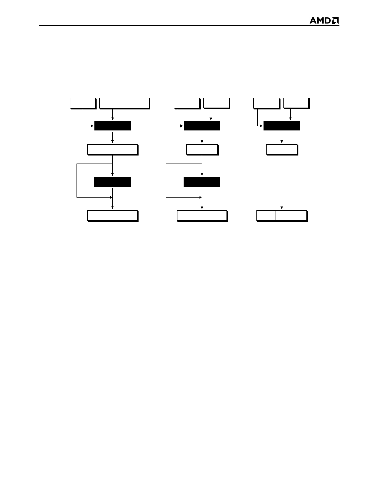
24592—Rev. 3.14—September 2007 AMD64 Technology
Protected Mode
031015
Effective Address (EA)Selector
Segmentation
031
Linear Address
Paging
031
Physical Address (PA)
Virtual-8086 Mode
015
Selector
Segmentation
Linear Address
Paging
Physical Address (PA)
EA
015
019
031
Figure 2-4. Legacy-Mode Memory Management
Real Mode
Selector
Segmentation
Linear Address
0
015
19 031
015
EA
019
PA
513-185.eps
The memory-management functions differ, depending on the submode, as follows:
• Protected Mode—Protected mode supports 16-bit and 32-bit programs with table-based memory
segmentation, paging, and privilege-checking. The segmentation function takes 32-bit effective
addresses and 16-bit segment selectors and produces 32-bit linear addresses into one of 16K
memory segments, each of which can be up to 4GB in size. Paging is optional. The 32-bit physical
addresses are either produced by the paging function or the linear addresses are used without
modification as physical addresses.
• Virtual-8086 Mode—Virtual-8086 mode supports 16-bit programs running as tasks under
protected mode. 20-bit linear addresses are formed in the same way as in real mode, but they can
optionally be translated through the paging function to form 32-bit physical addresses that access
up to 4GB of memory space.
• Real Mode—Real mode supports 16-bit programs using register-based shift-and-add
segmentation, but it does not support paging. Sixteen-bit effective addresses are zero-extended and
added to a 16-bit segment-base address that is left-shifted four bits, producing a 20-bit linear
address. The linear address is zero-extended to a 32-bit physical address that can access up to 1MB
of memory space.
Memory Model 13
Page 46
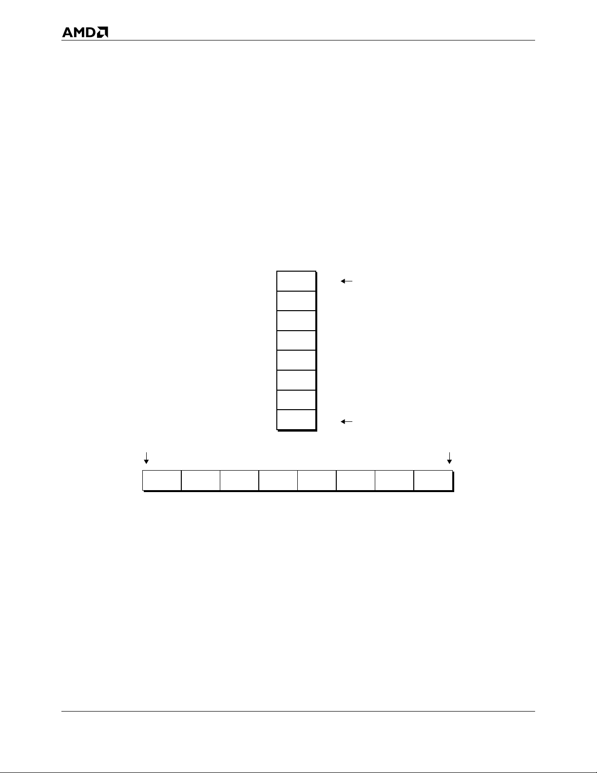
AMD64 Technology 24592—Rev. 3.14—September 2007
2.2 Memory Addressing
2.2.1 Byte Ordering
Instructions and data are stored in memory in little-endian byte order. Little-endian ordering places the
least-significant byte of the instruction or data item at the lowest memory address and the mostsignificant byte at the highest memory address.
Figure 2-5 shows a generalization of little-endian memory and register images of a quadword data
type. The least-significant byte is at the lowest address in memory and at the right-most byte location
of the register image.
Quadword in Memory
High (most-significant)
byte 7
byte 6
byte 5
byte 4
byte 3
byte 2
byte 1
byte 0
Quadword in General-Purpose Register
07h
06h
05h
04h
03h
02h
01h
00h
High (most-significant)
Low (least-significant)
Figure 2-5. Byte Ordering
Low (least-significant)
byte 0byte 1byte 2byte 3byte 4byte 5byte 6byte 7
063
513-116.eps
Figure 2-6 on page 15 shows the memory image of a 10-byte instruction. Instructions are byte data
types. They are read from memory one byte at a time, starting with the least-significant byte (lowest
address). For example, the following instruction specifies the 64-bit instruction MOV RAX,
1122334455667788 instruction that consists of the following ten bytes:
48 B8 8877665544332211
48 is a REX instruction prefix that specifies a 64-bit operand size, B8 is the opcode that—together with
the REX prefix—specifies the 64-bit RAX destination register, and 8877665544332211 is the 8-byte
immediate value to be moved, where 88 represents the eighth (least-significant) byte and 11 represents
14 Memory Model
Page 47
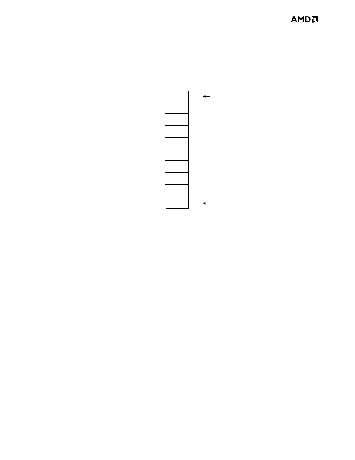
24592—Rev. 3.14—September 2007 AMD64 Technology
the first (most-significant) byte. In memory, the REX prefix byte (48) would be stored at the lowest
address, and the first immediate byte (11) would be stored at the highest instruction address.
11
22
33
44
55
66
77
88
B8
48
09h
08h
07h
06h
05h
04h
03h
02h
01h
00h
High (most-significant)
Low (least-significant)
513-186.eps
Figure 2-6. Example of 10-Byte Instruction in Memory
2.2.2 64-Bit Canonical Addresses
Long mode defines 64 bits of virtual address, but implementations of the AMD64 architecture may
support fewer bits of virtual address. Although implementations might not use all 64 bits of the virtual
address, they check bits 63 through the most-significant implemented bit to see if those bits are all
zeros or all ones. An address that complies with this property is said to be in canonical address form. If
a virtual-memory reference is not in canonical form, the implementation causes a general-protection
exception or stack fault.
2.2.3 Effective Addresses
Programs provide effective addresses to the hardware prior to segmentation and paging translations.
Long-mode effective addresses are a maximum of 64 bits wide, as shown in Figure 2-3 on page 12.
Programs running in compatibility mode generate (by default) 32-bit effective addresses, which the
hardware zero-extends to 64 bits. Legacy-mode effective addresses, with no address-size override, are
32 or 16 bits wide, as shown in Figure 2-4 on page 13. These sizes can be overridden with an addresssize instruction prefix, as described in “Instruction Prefixes” on page 71.
There are five methods for generating effective addresses, depending on the specific instruction
encoding:
• Absolute Addr esses—These addresses are given as displacements (or offsets) from the base address
of a data segment. They point directly to a memory location in the data segment.
Memory Model 15
Page 48
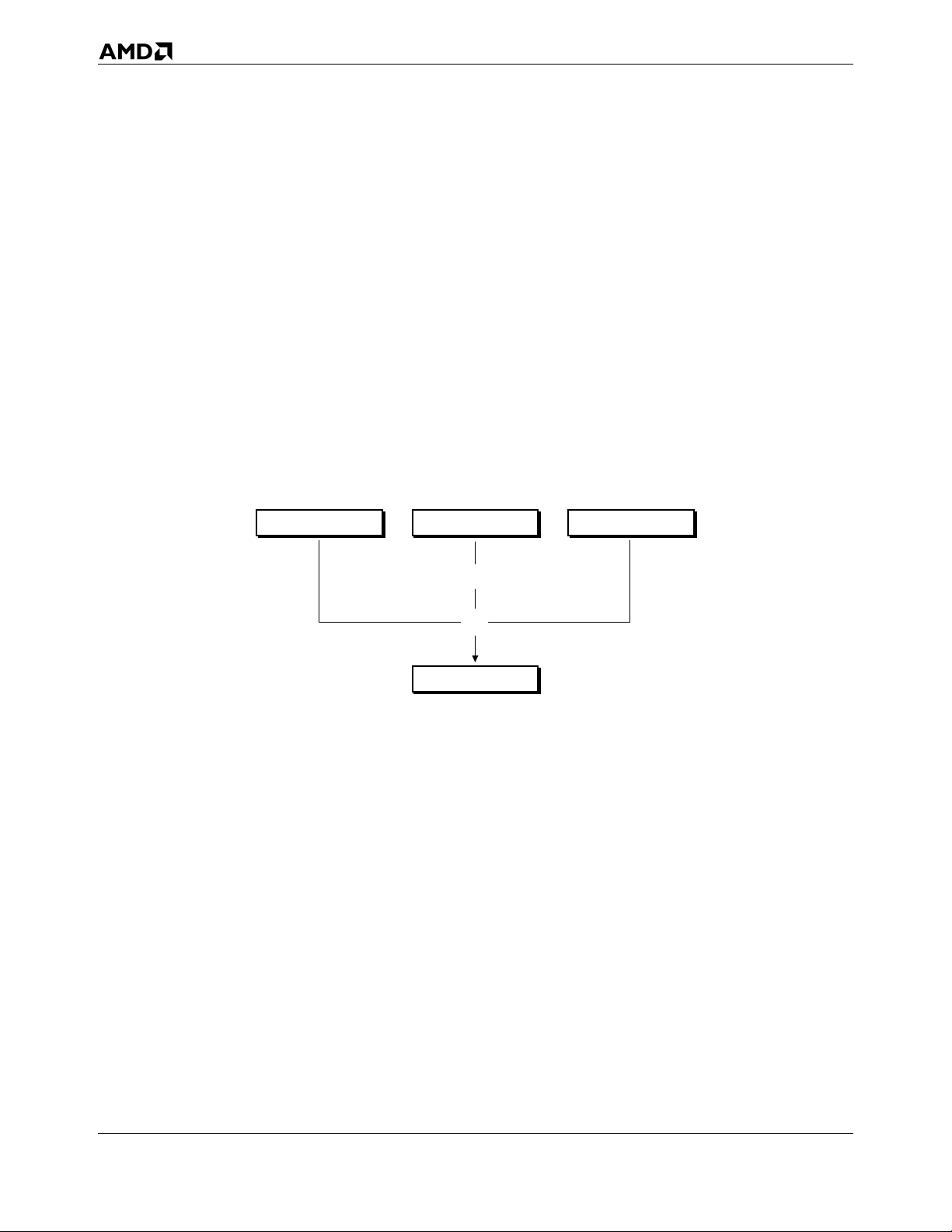
AMD64 Technology 24592—Rev. 3.14—September 2007
• Instruction-Relative Addresses—These addresses are given as displacements (or offsets) from the
current instruction pointer (IP), also called the program counter (PC). They are generated by
control-transfer instructions. A displacement in the instruction encoding, or one read from
memory, serves as an offset from the address that follows the transfer. See “RIP-Relative
Addressing” on page 18 for details about RIP-relative addressing in 64-bit mode.
• ModR/M Addr essing—These addresses are calculated using a scale, index, base, and displacement.
Instruction encodings contain two bytes—MODR/M and optional SIB (scale, index, base) and a
variable length displacement—that specify the variables for the calculation. The base and index
values are contained in general-purpose registers specified by the SIB byte. The scale and
displacement values are specified directly in the instruction encoding. Figure 2-7 shows the
components of a complex-address calculation. The resultant effective address is added to the datasegment base address to form a linear address, as described in “Segmented Virtual Memory” in
Volume 2. “Instruction Formats” in Volume 3 gives further details on specifying this form of
address. The encoding of instructions specifies how the address is calculated.
Base
Scale by 1, 2, 4, or 8
*
DisplacementIndex
+
Effective Address
513-108.eps
Figure 2-7. Complex Address Calculation (Protected Mode)
• Stack Addresses—PUSH, POP, CALL, RET, IRET, and INT instructions implicitly use the stack
pointer, which contains the address of the procedure stack. See “Stack Operation” on page 19 for
details about the size of the stack pointer.
• S tring Addresses—String instructions generate sequential addresses using the rDI and rSI registers,
as described in “Implicit Uses of GPRs” on page 30.
In 64-bit mode, with no address-size override, the size of effective-address calculations is 64 bits. An
effective-address calculation uses 64-bit base and index registers and sign-extends displacements to 64
bits. Due to the flat address space in 64-bit mode, virtual addresses are equal to effective addresses.
(For an exception to this general rule, see “FS and GS as Base of Address Calculation” on page 17.)
Long-Mode Zero-Extension of 16-Bit and 32-Bit Addresses. In long mode, all 16-bit and 32-bit
address calculations are zero-extended to form 64-bit addresses. Address calculations are first
16 Memory Model
Page 49
24592—Rev. 3.14—September 2007 AMD64 Technology
truncated to the effective-address size of the current mode (64-bit mode or compatibility mode), as
overridden by any address-size prefix. The result is then zero-extended to the full 64-bit address width.
Because of this, 16-bit and 32-bit applications running in compatibility mode can access only the low
4GB of the long-mode virtual-address space. Likewise, a 32-bit address generated in 64-bit mode can
access only the low 4GB of the long-mode virtual-address space.
Displacements and Immediates. In general, the maximum size of address displacements and
immediate operands is 32 bits. They can be 8, 16, or 32 bits in size, depending on the instruction or, for
displacements, the effective address size. In 64-bit mode, displacements are sign-extended to 64 bits
during use, but their actual size (for value representation) remains a maximum of 32 bits. The same is
true for immediates in 64-bit mode, when the operand size is 64 bits. However, support is provided in
64-bit mode for some 64-bit displacement and immediate forms of the MOV instruction.
FS and GS as Base of Address Calculation. In 64-bit mode, the FS and GS segment-base registers
(unlike the DS, ES, and SS segment-base registers) can be used as non-zero data-segment base
registers for address calculations, as described in “Segmented Virtual Memory” in Volume 2. 64-bit
mode assumes all other data-segment registers (DS, ES, and SS) have a base address of 0.
2.2.4 Address-Size Prefix
The default address size of an instruction is determined by the default-size (D) bit and long-mode (L)
bit in the current code-segment descriptor (for details, see “Segmented Virtual Memory” in Volume 2).
Application software can override the default address size in any operating mode by using the 67h
address-size instruction prefix byte. The address-size prefix allows mixing 32-bit and 64-bit addresses
on an instruction-by-instruction basis.
Table 2-1 on page 18 shows the effects of using the address-size prefix in all operating modes. In 64bit mode, the default address size is 64 bits. The address size can be overridden to 32 bits. 16-bit
addresses are not supported in 64-bit mode. In compatibility and legacy modes, the address-size prefix
works the same as in the legacy x86 architecture.
Memory Model 17
Page 50
AMD64 Technology 24592—Rev. 3.14—September 2007
Table 2-1. Address-Size Prefixes
Default
Operating Mode
64-Bit Mode 64
Long Mode
Compatibility Mode
Legacy Mode
(Protected, Virtual-8086, or Real
Mode)
Note:
1. “No” indicates that the default address size is used.
Address
Size (Bits)
32
16
32
16
Effective
Address Size
(Bits)
64 no
32 yes
32 no
16 yes
32 yes
16 no
32 no
16 yes
32 yes
16 no
Address-
Size Prefix
1
(67h)
Required?
2.2.5 RIP-Relative Addressing
RIP-relative addressing—that is, addressing relative to the 64-bit instruction pointer (also called
program counter)—is available in 64-bit mode. The effective address is formed by adding the
displacement to the 64-bit RIP of the next instruction.
In the legacy x86 architecture, addressing relative to the instruction pointer (IP or EIP) is available
only in control-transfer instructions. In the 64-bit mode, any instruction that uses ModRM addressing
(see “ModRM and SIB Bytes” in Volume 3) can use RIP-relative addressing. The feature is
particularly useful for addressing data in position-independent code and for code that addresses global
data.
Programs usually have many references to data, especially global data, that are not register-based. To
load such a program, the loader typically selects a location for the program in memory and then adjusts
the program’s references to global data based on the load location. RIP-relative addressing of data
makes this adjustment unnecessary.
Range of RIP-Relative Addressing. Without RIP-relative addressing, instructions encoded with a
ModRM byte address memory relative to zero. With RIP-relative addressing, instructions with a
ModRM byte can address memory relative to the 64-bit RIP using a signed 32-bit displacement. This
provides an offset range of ±2 GBytes from the RIP.
Effect of Address-Size Prefix on RIP-Relative Addressing. RIP-relative addressing is enabled by
64-bit mode, not by a 64-bit address-size. Conversely, use of the address-size prefix does not disable
18 Memory Model
Page 51
24592—Rev. 3.14—September 2007 AMD64 Technology
RIP-relative addressing. The effect of the address-size prefix is to truncate and zero-extend the
computed effective address to 32 bits, like any other addressing mode.
Encoding. For details on instruction encoding of RIP-relative addressing, see in “RIP-Relative
Addressing” in Volume 3.
2.3 Pointers
Pointers are variables that contain addresses rather than data. They are used by instructions to
reference memory. Instructions access data using near and far pointers. Stack pointers locate the
current stack.
2.3.1 Near and Far Pointers
Near pointers contain only an effective address, which is used as an offset into the current segment. Far
pointers contain both an effective address and a segment selector that specifies one of several
segments. Figure 2-8 illustrates the two types of pointers.
Far PointerNear Pointer
Effective Address (EA) Effective Address (EA)Selector
513-109.eps
Figure 2-8. Near and Far Pointers
In 64-bit mode, the AMD64 architecture supports only the flat-memory model in which there is only
one data segment, so the effective address is used as the virtual (linear) address and far pointers are not
needed. In compatibility mode and legacy protected mode, the AMD64 architecture supports multiple
memory segments, so effective addresses can be combined with segment selectors to form far pointers,
and the terms logical address (segment selector and effective address) and far pointer are synonyms.
Near pointers can also be used in compatibility mode and legacy mode.
2.4 Stack Operation
A stack is a portion of a stack segment in memory that is used to link procedures. Software conventions
typically define stacks using a stack frame, which consists of two registers—a stack-fram e base
pointer (rBP) and a stack pointer (rSP)—as shown in Figure 2-9 on page 20. These stack pointers can
be either near pointers or far pointers.
The stack-segment (SS) register, points to the base address of the current stack segment. The stack
pointers contain offsets from the base address of the current stack segment. All instructions that
address memory using the rBP or rSP registers cause the processor to access the current stack segment.
Memory Model 19
Page 52
AMD64 Technology 24592—Rev. 3.14—September 2007
Stack Frame Before Procedure Call Stack Frame After Procedure Call
Stack-Frame Base Pointer (rBP)
and Stack Pointer (rSP)
Stack-Segment (SS) Base Address
Stack-Frame Base Pointer (rBP)
Stack Pointer (rSP)
Stack-Segment (SS) Base Address
passed data
513-110.eps
Figure 2-9. Stack Pointer Mechanism
In typical APIs, the stack-frame base pointer and the stack pointer point to the same location before a
procedure call (the top-of-stack of the prior stack frame). After data is pushed onto the stack, the stackframe base pointer remains where it was and the stack pointer advances downward to the address
below the pushed data, where it becomes the new top-of-stack.
In legacy and compatibility modes, the default stack pointer size is 16 bits (SP) or 32 bits (ESP),
depending on the default-size (B) bit in the stack-segment descriptor, and multiple stacks can be
maintained in separate stack segments. In 64-bit mode, stack pointers are always 64 bits wide (RSP).
Further application-programming details on the stack mechanism are described in “Control Transfers”
on page 76. System-programming details on the stack segments are described in “Segmented Virtual
Memory” in Volume 2.
2.5 Instruction Pointer
The instruction pointer is used in conjunction with the code-segment (CS) register to locate the next
instruction in memory. The instruction-pointer register contains the displacement (offset)—from the
base address of the current CS segment, or from address 0 in 64-bit mode—to the next instruction to be
executed. The pointer is incremented sequentially, except for branch instructions, as described in
“Control Transfers” on page 76.
In legacy and compatibility modes, the instruction pointer is a 16-bit (IP) or 32-bit (EIP) register. In
64-bit mode, the instruction pointer is extended to a 64-bit (RIP) register to support 64-bit offsets. The
case-sensitive acronym, rIP, is used to refer to any of these three instruction-pointer sizes, depending
on the software context.
Figure 2-10 on page 21 shows the relationship between RIP, EIP, and IP. The 64-bit RIP can be used
for RIP-relative addressing, as described in “RIP-Relative Addressing” on page 18.
20 Memory Model
Page 53
24592—Rev. 3.14—September 2007 AMD64 Technology
IP
EIP
RIP
63 31 032
513-140.eps
rIP
Figure 2-10. Instruction Pointer (rIP) Register
The contents of the rIP are not directly readable by software. However, the rIP is pushed onto the stack
by a call instruction.
The memory model described in this chapter is used by all of the programming environments that
make up the AMD64 architecture. The next four chapters of this volume describe the application
programming environments, which include:
• General-purpose programming (Chapter 3 on page 23).
• 128-bit media programming (Chapter 4 on page 105).
• 64-bit media programming (Chapter 5 on page 193).
• x87 floating-point programming (Chapter 6 on page 237).
Memory Model 21
Page 54
AMD64 Technology 24592—Rev. 3.14—September 2007
22 Memory Model
Page 55
24592—Rev. 3.14—September 2007 AMD64 Technology
3 General-Purpose Programming
The general-purpose programming model includes the general-purpose registers (GPRs), integer
instructions and operands that use the GPRs, program-flow control methods, memory optimization
methods, and I/O. This programming model includes the original x86 integer-programming
architecture, plus 64-bit extensions and a few additional instructions. Only the applicationprogramming instructions and resources are described in this chapter. Integer instructions typically
used in system programming, including all of the privileged instructions, are described in Volume 2,
along with other system-programming topics.
The general-purpose programming model is used to some extent by almost all programs, including
programs consisting primarily of 128-bit media instructions, 64-bit media instructions, x87 floatingpoint instructions, or system instructions. For this reason, an understanding of the general-purpose
programming model is essential for any programming work using the AMD64 instruction set
architecture.
3.1 Registers
Figure 3-1 on page 24 shows an overview of the registers used in general-purpose application
programming. They include the general-purpose registers (GPRs), segment registers, flags register,
and instruction-pointer register. The number and width of available registers depends on the operating
mode.
The registers and register ranges shaded light gray in Figure 3-1 on page 24 are available only in 64-bit
mode. Those shaded dark gray are available only in legacy mode and compatibility mode. Thus, in 64-
bit mode, the 32-bit general-purpose, flags, and instruction-pointer registers available in legacy mode
and compatibility mode are extended to 64-bit widths, eight new GPRs are available, and the DS, ES,
and SS segment registers are ignored.
When naming registers, if reference is made to multiple register widths, a lower-case r notation is
used. For example, the notation rAX refers to the 16-bit AX, 32-bit EAX, or 64-bit RAX register,
depending on an instruction’s effective operand size.
General-Purpose Programming 23
Page 56
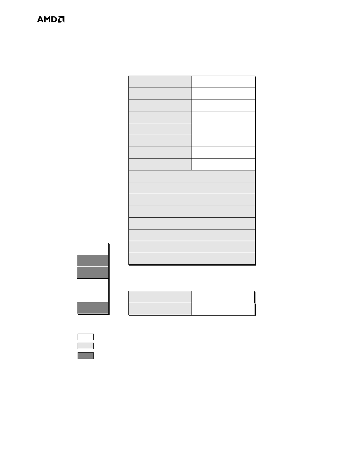
AMD64 Technology 24592—Rev. 3.14—September 2007
General-Purpose Registers (GPRs)
rAX
rBX
rCX
rDX
rBP
rSI
rDI
rSP
R8
R9
Segment
Registers
CS
DS
ES
FS
GS
SS
15 0
Available to sofware in all modes
Available to sofware only in 64-bit mode
Ignored by hardware in 64-bit mode
R10
R11
R12
R13
R14
R15
63 31 032
Flags and Instruction Pointer Registers
rFLAGS
rIP
63 31 032
513-131.eps
Figure 3-1. General-Purpose Programming Registers
3.1.1 Legacy Registers
In legacy and compatibility modes, all of the legacy x86 registers are available. Figure 3-2 on page 25
shows a detailed view of the GPR, flag, and instruction-pointer registers.
24 General-Purpose Programming
Page 57
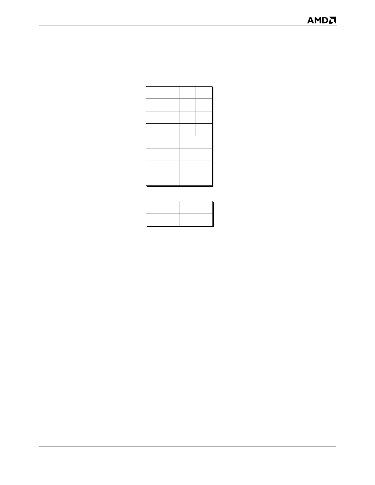
24592—Rev. 3.14—September 2007 AMD64 Technology
register
encoding
0
3
1
2
6
7
5
4
low
high
8-bit
8-bit 32-bit
AH (4)
BH (7)
CH (5)
DH (6)
31 15 016
31 0
AL
BL
CL
DL
SI
DI
BP
SP
FLAGS
IP
16-bit
AX
BX
CX
DX
SI
DI
BP
SP
FLAGSIPEFLAGS
EAX
EBX
ECX
EDX
ESI
EDI
EBP
ESP
EIP
513-311.eps
Figure 3-2. General Registers in Legacy and Compatibility Modes
The legacy GPRs include:
• Eight 8-bit registers (AH, AL, BH, BL, CH, CL, DH, DL).
• Eight 16-bit registers (AX, BX, CX, DX, DI, SI, BP, SP).
• Eight 32-bit registers (EAX, EBX, ECX, EDX, EDI, ESI, EBP, ESP).
The size of register used by an instruction depends on the effective operand size or, for certain
instructions, the opcode, address size, or stack size. The 16-bit and 32-bit registers are encoded as 0
through 7 in Figure 3-2. For opcodes that specify a byte operand, registers encoded as 0 through 3 refer
to the low-byte registers (AL, BL, CL, DL) and registers encoded as 4 through 7 refer to the high-byte
registers (AH, BH, CH, DH).
The 16-bit FLAGS register, which is also the low 16 bits of the 32-bit EFLAGS register, shown in
Figure 3-2, contains control and status bits accessible to application software, as described in
Section 3.1.4, “Flags Register,” on page 33. The 16-bit IP or 32-bit EIP instruction-pointer register
contains the address of the next instruction to be executed, as described in Section 2.5, “Instruction
Pointer,” on page 20.
General-Purpose Programming 25
Page 58
AMD64 Technology 24592—Rev. 3.14—September 2007
3.1.2 64-Bit-Mode Registers
In 64-bit mode, eight new GPRs are added to the eight legacy GPRs, all 16 GPRs are 64 bits wide, and
the low bytes of all registers are accessible. Figure 3-3 on page 27 shows the GPRs, flags register, and
instruction-pointer register available in 64-bit mode. The GPRs include:
• Sixteen 8-bit low-byte registers (AL, BL, CL, DL, SIL, DIL, BPL, SPL, R8B, R9B, R10B, R11B,
R12B, R13B, R14B, R15B).
• Four 8-bit high-byte registers (AH, BH, CH, DH), addressable only when no REX prefix is used.
• Sixteen 16-bit registers (AX, BX, CX, DX, DI, SI, BP, SP, R8W, R9W, R10W, R11W, R12W,
R13W, R14W, R15W).
• Sixteen 32-bit registers (EAX, EBX, ECX, EDX, EDI, ESI, EBP, ESP, R8D, R9D, R10D, R11D,
R12D, R13D, R14D, R15D).
• Sixteen 64-bit registers (RAX, RBX, RCX, RDX, RDI, RSI, RBP, RSP, R8, R9, R10, R11, R12,
R13, R14, R15).
The size of register used by an instruction depends on the effective operand size or, for certain
instructions, the opcode, address size, or stack size. For most instructions, access to the extended GPRs
requires a REX prefix (Section 3.5.2, “REX Prefixes,” on page 74). The four high-byte registers (AH,
BH, CH, DH) available in legacy mode are not addressable when a REX prefix is used.
In general, byte and word operands are stored in the low 8 or 16 bits of GPRs without modifying their
high 56 or 48 bits, respectively. Doubleword operands, however, are normally stored in the low 32 bits
of GPRs and zero-extended to 64 bits.
The 64-bit RFLAGS register, shown in Figure 3-3 on page 27, contains the legacy EFLAGS in its low
32-bit range. The high 32 bits are reserved. They can be written with anything but they always read as
zero (RAZ). The 64-bit RIP instruction-pointer register contains the address of the next instruction to
be executed, as described in Section 3.1.5, “Instruction Pointer Register,” on page 36.
26 General-Purpose Programming
Page 59
24592—Rev. 3.14—September 2007 AMD64 Technology
not modified for 8-bit operands
not modified for 16-bit operands
register
encoding
zero-extended
for 32-bit operands
low
16-bit 32-bit 64-bit
8-bit
0
3
1
2
AH*
BH*
CH*
DH*
6
7
5
4
8
9
10
11
12
13
14
AL
BL
CL
DL
SIL**
DIL**
BPL**
SPL**
R8B
R9B
R10B
R11B
R12B
R13B
R14B
AX
BX
CX
DX
SI
DI
BP
SP
R8W
R9W
R10W
R11W
R12W
R13W
R14W
EAX
EBX
ECX
EDX
ESI
EDI
EBP
ESP
R8D
R9D
R10D
R11D
R12D
R13D
R14D
RAX
RBX
RCX
RDX
RSI
RDI
RBP
RSP
R8
R9
R10
R11
R12
R13
R14
15
63 31 15 7 081632
0
R15B
R15W
RFLAGS
R15D
R15
513-309.eps
RIP
63 31 032
* Not addressable when
a REX prefix is used.
** Only addressable when
a REX prefix is used.
Figure 3-3. General Registers in 64-Bit Mode
Figure 3-4 on page 28 illustrates another way of viewing the 64-bit-mode GPRs, showing how the
legacy GPRs overlap the extended GPRs. Gray-shaded bits are not modified in 64-bit mode.
General-Purpose Programming 27
Page 60
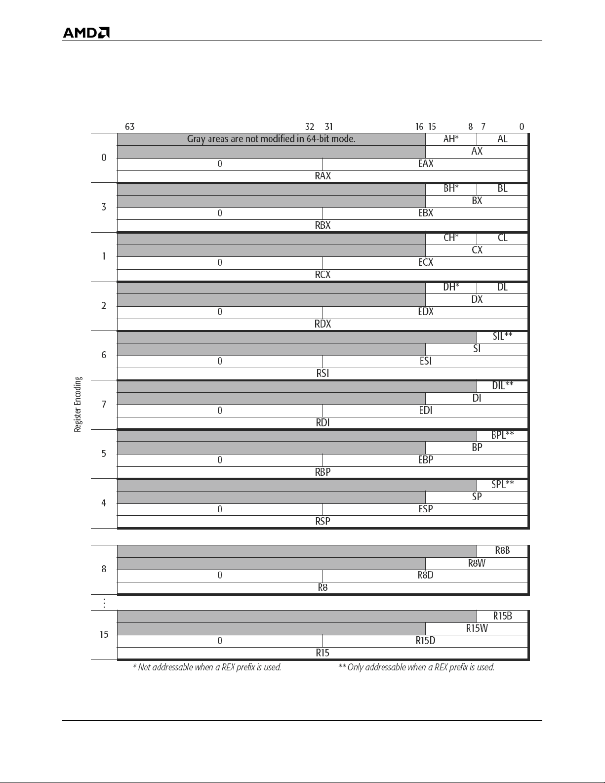
AMD64 Technology 24592—Rev. 3.14—September 2007
Figure 3-4. GPRs in 64-Bit Mode
28 General-Purpose Programming
Page 61
24592—Rev. 3.14—September 2007 AMD64 Technology
Default Operand Size. For most instructions, the default operand size in 64-bit mode is 32 bits. To
access 16-bit operand sizes, an instruction must contain an operand-size prefix (66h), as described in
Section 3.2.2, “Operand Sizes and Overrides,” on page 39. To access the full 64-bit operand size, most
instructions must contain a REX prefix.
For details on operand size, see Section 3.2.2, “Operand Sizes and Overrides,” on page 39.
Byte Registers. 64-bit mode provides a uniform set of low-byte, low-word, low-doubleword, and
quadword registers that is well-suited for register allocation by compilers. Access to the four new lowbyte registers in the legacy-GPR range (SIL, DIL, BPL, SPL), or any of the low-byte registers in the
extended registers (R8B–R15B), requires a REX instruction prefix. However, the legacy high-byte
registers (AH, BH, CH, DH) are not accessible when a REX prefix is used.
Zero-Extension of 32-Bit Results. As Figure 3-3 on page 27 and Figure 3-4 on page 28 show, when
performing 32-bit operations with a GPR destination in 64-bit mode, the processor zero-extends the
32-bit result into the full 64-bit destination. 8-bit and 16-bit operations on GPRs preserve all unwritten
upper bits of the destination GPR. This is consistent with legacy 16-bit and 32-bit semantics for
partial-width results.
Software should explicitly sign-extend the results of 8-bit, 16-bit, and 32-bit operations to the full 64bit width before using the results in 64-bit address calculations.
The following four code examples show how 64-bit, 32-bit, 16-bit, and 8-bit ADDs work. In these
examples, “48” is a REX prefix specifying 64-bit operand size, and “01C3” and “00C3” are the opcode
and ModRM bytes of each instruction (see “Opcode Syntax” in Volume 3 for details on the opcode and
ModRM encoding).
Example 1: 64-bit Add:
Before:RAX =0002_0001_8000_2201
RBX =0002_0002_0123_3301
48 01C3 ADD RBX,RAX ;48 is a REX prefix for size.
Result:RBX = 0004_0003_8123_5502
Example 2: 32-bit Add:
Before:RAX = 0002_0001_8000_2201
RBX = 0002_0002_0123_3301
01C3 ADD EBX,EAX ;32-bit add
Result:RBX = 0000_0000_8123_5502
(32-bit result is zero extended)
Example 3: 16-bit Add:
Before:RAX = 0002_0001_8000_2201
RBX = 0002_0002_0123_3301
General-Purpose Programming 29
Page 62
AMD64 Technology 24592—Rev. 3.14—September 2007
66 01C3 ADD BX,AX ;66 is 16-bit size override
Result:RBX = 0002_0002_0123_5502
(bits 63:16 are preserved)
Example 4: 8-bit Add:
Before:RAX = 0002_0001_8000_2201
RBX = 0002_0002_0123_3301
00C3 ADD BL,AL ;8-bit add
Result:RBX = 0002_0002_0123_3302
(bits 63:08 are preserved)
GPR High 32 Bits Across Mode Switches. The processor does not preserve the upper 32 bits of the
64-bit GPRs across switches from 64-bit mode to compatibility or legacy modes. When using 32-bit
operands in compatibility or legacy mode, the high 32 bits of GPRs are undefined. Software must not
rely on these undefined bits, because they can change from one implementation to the next or even on
a cycle-to-cycle basis within a given implementation. The undefined bits are not a function of the data
left by any previously running process.
3.1.3 Implicit Uses of GPRs
Most instructions can use any of the GPRs for operands. However, as Figure 3-1 on page 31 shows,
some instructions use some GPRs implicitly. Details about implicit use of GPRs are described in
“General-Purpose Instruction Reference” in Volume 3.
Table 3-1 on page 31 shows implicit register uses only for application instructions. Certain system
instructions also make implicit use of registers. These system instructions are described in “System
Instruction Reference” in Volume 3.
30 General-Purpose Programming
Page 63
24592—Rev. 3.14—September 2007 AMD64 Technology
Table 3-1. Implicit Uses of GPRs
Registers
1
Low 8-Bit 16-Bit 32-Bit 64-Bit
AL AX EAX RAX
BL BX EBX RBX
CL CX ECX RCX
DL DX EDX RDX
2
SIL
Note:
1. Gray-shaded registers have no implicit uses.
2. Accessible only in 64-bit mode.
SI ESI RSI
Name Implicit Uses
• Operand for decimal
arithmetic, multiply, divide,
string, compare-andexchange, table-translation,
and I/O instructions.
2
Accumulator
• Special accumulator encoding
for ADD, XOR, and MOV
instructions.
• Used with EDX to hold doubleprecision operands.
• CPUID processor-feature
information.
• Address generation in 16-bit
code.
2
Base
• Memory address for XLAT
instruction.
• CPUID processor-feature
information.
• Bit index for shift and rotate
instructions.
• Iteration count for loop and
2
Count
repeated string instructions.
• Jump conditional if zero.
• CPUID processor-feature
information.
• Operand for multiply and divide
instructions.
• Port number for I/O
2
I/O Address
instructions.
• Used with EAX to hold doubleprecision operands.
• CPUID processor-feature
information.
• Memory address of source
2
Source Index
operand for string instructions.
• Memory index for 16-bit
addresses.
General-Purpose Programming 31
Page 64
AMD64 Technology 24592—Rev. 3.14—September 2007
Table 3-1. Implicit Uses of GPRs (continued)
Registers
1
Name Implicit Uses
Low 8-Bit 16-Bit 32-Bit 64-Bit
• Memory address of destination
DIL
2
DI EDI RDI
2
Destination
Index
operand for string instructions.
• Memory index for 16-bit
addresses.
2
BPL
SPL
2
BP EBP RBP
SP ESP RSP
R8B–R10B2R8W–R10W2R8D–R10D
2
R11B
R12W–R15W
R12B–R15B
Note:
1. Gray-shaded registers have no implicit uses.
2. Accessible only in 64-bit mode.
2
R11W
2
2
R11D
R12D–R15D2R12–R15
2
2
2
R8–R10
2
R11
2
Base Pointer
Stack Pointer
2
2
None No implicit uses
None
None No implicit uses
• Memory address of stackframe base pointer.
• Memory address of last stack
entry (top of stack).
• Holds the value of RFLAGS on
SYSCALL/SYSRET.
Arithmetic Operations. Several forms of the add, subtract, multiply, and divide instructions use AL
or rAX implicitly. The multiply and divide instructions also use the concatenation of rDX:rAX for
double-sized results (multiplies) or quotient and remainder (divides).
Sign-Extensions. The instructions that double the size of operands by sign extension (for example,
CBW, CWDE, CDQE, CWD, CDQ, CQO) use rAX register implicitly for the operand. The CWD,
CDQ, and CQO instructions also uses the rDX register.
Special MOVs. The MOV instruction has several opcodes that implicitly use the AL or rAX register
for one operand.
String Operations. Many types of string instructions use the accumulators implicitly. Load string,
store string, and scan string instructions use AL or rAX for data and rDI or rSI for the offset of a
memory address.
I/O-Address-Space Operations. The I/O and string I/O instructions use rAX to hold data that is
received from or sent to a device located in the I/O-address space. DX holds the device I/O-address
(the port number).
Table Translations. The table translate instruction (XLATB) uses AL for an memory index and rBX
for memory base address.
Compares and Exchanges. Compare and exchange instructions (CMPXCHG) use the AL or rAX
register for one operand.
32 General-Purpose Programming
Page 65
24592—Rev. 3.14—September 2007 AMD64 Technology
Decimal Arithmetic. The decimal arithmetic instructions (AAA, AAD, AAM, AAS, DAA, DAS)
that adjust binary-coded decimal (BCD) operands implicitly use the AL and AH register for their
operations.
Shifts and Rotates. Shift and rotate instructions can use the CL register to specify the number of bits
an operand is to be shifted or rotated.
Conditional Jumps. Special conditional-jump instructions use the rCX register instead of flags. The
JCXZ and JrCXZ instructions check the value of the rCX register and pass control to the target
instruction when the value of rCX register reaches 0.
Repeated String Operations. With the exception of I/O string instructions, all string operations use
rSI as the source-operand pointer and rDI as the destination-operand pointer. I/O string instructions
use rDX to specify the input-port or output-port number. For repeated string operations (those
preceded with a repeat-instruction prefix), the rSI and rDI registers are incremented or decremented as
the string elements are moved from the source location to the destination. Repeat-string operations
also use rCX to hold the string length, and decrement it as data is moved from one location to the other.
Stack Operations. Stack operations make implicit use of the rSP register, and in some cases, the rBP
register. The rSP register is used to hold the top-of-stack pointer (or simply, stack pointer). rSP is
decremented when items are pushed onto the stack, and incremented when they are popped off the
stack. The ENTER and LEAVE instructions use rBP as a stack-frame base pointer. Here, rBP points to
the last entry in a data structure that is passed from one block-structured procedure to another.
The use of rSP or rBP as a base register in an address calculation implies the use of SS (stack segment)
as the default segment. Using any other GPR as a base register without a segment-override prefix
implies the use of the DS data segment as the default segment.
The push all and pop all instructions (PUSHA, PUSHAD, POPA, POPAD) implicitly use all of the
GPRs.
CPUID Information. The CPUID instruction makes implicit use of the EAX, EBX, ECX, and EDX
registers. Software loads a function code into EAX, executes the CPUID instruction, and then reads the
associated processor-feature information in EAX, EBX, ECX, and EDX.
3.1.4 Flags Register
Figure 3-5 on page 34 shows the 64-bit RFLAGS register and the flag bits visible to application
software. Bits 15–0 are the FLAGS register (accessed in legacy real and virtual-8086 modes), bits
31–0 are the EFLAGS register (accessed in legacy protected mode and compatibility mode), and bits
63–0 are the RFLAGS register (accessed in 64-bit mode). The name rFLAGS refers to any of the three
register widths, depending on the current software context.
General-Purpose Programming 33
Page 66
AMD64 Technology 24592—Rev. 3.14—September 2007
63 32
Reserved, RAZ
31 1211109876543210
See Volume 2 for System Flags
Bits Mnemonic Description R/W
11 OF Overflow Flag R/W
10 DF Direction Flag R/W
7 SF Sign Flag R/W
6 ZF Zero Flag R/W
4 AF Auxiliary Carry Flag R/W
2 PF Parity Flag R/W
0 CF Carry Flag R/W
OFD
F
SFZ
A
F
F
P
F
C
F
Figure 3-5. rFLAGS Register—Flags Visible to Application Software
The low 16 bits (FLAGS portion) of rFLAGS are accessible by application software and hold the
following flags:
• One control flag (the direction flag DF).
• Six status flags (carry flag CF, parity flag PF, auxiliary carry flag AF, zero flag ZF, sign flag SF,
and overflow flag OF).
The direction flag (DF) flag controls the direction of string operations. The status flags provide result
information from logical and arithmetic operations and control information for conditional move and
jump instructions.
Bits 31–16 of the rFLAGS register contain flags that are accessible only to system software. These
flags are described in “System Registers” in Volume 2. The highest 32 bits of RFLAGS are reserved.
In 64-bit mode, writes to these bits are ignored. They are read as zeros (RAZ). The rFLAGS register is
initialized to 02h on reset, so that all of the programmable bits are cleared to zero.
The effects that rFLAGS bit-values have on instructions are summarized in the following places:
• Conditional Moves (CMOVcc)—Table 3-4 on page 43.
• Conditional Jumps (Jcc)—Table 3-5 on page 55.
• Conditional Sets (SETcc)—Table 3-6 on page 59.
The effects that instructions have on rFLAGS bit-values are summarized in “Instruction Effects on
RFLAGS” in Volume 3.
34 General-Purpose Programming
Page 67
24592—Rev. 3.14—September 2007 AMD64 Technology
The sections below describe each application-visible flag. All of these flags are readable and writable.
For example, the POPF, POPFD, POPFQ, IRET, IRETD, and IRETQ instructions write all flags. The
carry and direction flags are writable by dedicated application instructions. Other application-visible
flags are written indirectly by specific instructions. Reserved bits and bits whose writability is
prevented by the current values of system flags, current privilege level (CPL), or the current operating
mode, are unaffected by the POPFx instructions.
Carry Flag (CF). Bit 0. Hardware sets the carry flag to 1 if the last integer addition or subtraction
operation resulted in a carry (for addition) or a borrow (for subtraction) out of the most-significant bit
position of the result. Otherwise, hardware clears the flag to 0.
The increment and decrement instructions—unlike the addition and subtraction instructions—do not
affect the carry flag. The bit shift and bit rotate instructions shift bits of operands into the carry flag.
Logical instructions like AND, OR, XOR clear the carry flag. Bit-test instructions (BTx) set the value
of the carry flag depending on the value of the tested bit of the operand.
Software can set or clear the carry flag with the STC and CLC instructions, respectively. Software can
complement the flag with the CMC instruction.
Parity Flag (PF). Bit 2. Hardware sets the parity flag to 1 if there is an even number of 1 bits in the
least-significant byte of the last result of certain operations. Otherwise (i.e., for an odd number of 1
bits), hardware clears the flag to 0. Software can read the flag to implement parity checking.
Auxiliary Carry Flag (AF). Bit 4. Hardware sets the auxiliary carry flag to 1 if the last binary-coded
decimal (BCD) operation resulted in a carry (for addition) or a borrow (for subtraction) out of bit 3.
Otherwise, hardware clears the flag to 0.
The main application of this flag is to support decimal arithmetic operations. Most commonly, this flag
is used internally by correction commands for decimal addition (AAA) and subtraction (AAS).
Zero Flag (ZF). Bit 6. Hardware sets the zero flag to 1 if the last arithmetic operation resulted in a
value of zero. Otherwise (for a non-zero result), hardware clears the flag to 0. The compare and test
instructions also affect the zero flag.
The zero flag is typically used to test whether the result of an arithmetic or logical operation is zero, or
to test whether two operands are equal.
Sign Flag (SF). Bit 7. Hardware sets the sign flag to 1 if the last arithmetic operation resulted in a
negative value. Otherwise (for a positive-valued result), hardware clears the flag to 0. Thus, in such
operations, the value of the sign flag is set equal to the value of the most-significant bit of the result.
Depending on the size of operands, the most-significant bit is bit 7 (for bytes), bit 15 (for words), bit 31
(for doublewords), or bit 63 (for quadwords).
Direction Flag (DF). Bit 10. The direction flag determines the order in which strings are processed.
Software can set the direction flag to 1 to specify decrementing the data pointer for the next string
instruction (LODSx, STOSx, MOVSx, SCASx, CMPSx, OUTSx, or INSx). Clearing the direction flag
General-Purpose Programming 35
Page 68
AMD64 Technology 24592—Rev. 3.14—September 2007
to 0 specifies incrementing the data pointer. The pointers are stored in the rSI or rDI register. Software
can set or clear the flag with the STD and CLD instructions, respectively.
Overflow Flag (OF). Bit 11. Hardware sets the overflow flag to 1 to indicate that the most-significant
(sign) bit of the result of the last signed integer operation differed from the signs of both source
operands. Otherwise, hardware clears the flag to 0. A set overflow flag means that the magnitude of the
positive or negative result is too big (overflow) or too small (underflow) to fit its defined data type.
The OF flag is undefined after the DIV instruction and after a shift of more than one bit. Logical
instructions clear the overflow flag.
3.1.5 Instruction Pointer Register
The instruction pointer register—IP, EIP, or RIP, or simply rIP for any of the three depending on the
context—is used in conjunction with the code-segment (CS) register to locate the next instruction in
memory. See Section 2.5, “Instruction Pointer,” on page 20 for details.
3.2 Operands
Operands are either referenced by an instruction's encoding or included as an immediate value in the
instruction encoding. Depending on the instruction, referenced operands can be located in registers,
memory locations, or I/O ports.
3.2.1 Data Types
Figure 3-6 on page 37 shows the register images of the general-purpose data types. In the generalpurpose programming environment, these data types can be interpreted by instruction syntax or the
software context as the following types of numbers and strings:
• Signed (two's-complement) integers.
• Unsigned integers.
• BCD digits.
• Packed BCD digits.
• Strings, including bit strings.
The double quadword data type is supported in the RDX:RAX registers by the MUL, IMUL, DIV,
IDIV, and CQO instructions. Software can interpret the data types in ways other than those shown in
Figure 3-6 on page 37 but the AMD64 instruction set does not directly support such interpretations
and software must handle them entirely on its own.
Table 3-2 on page 37 shows the range of representable values for the general-purpose data types.
36 General-Purpose Programming
Page 69
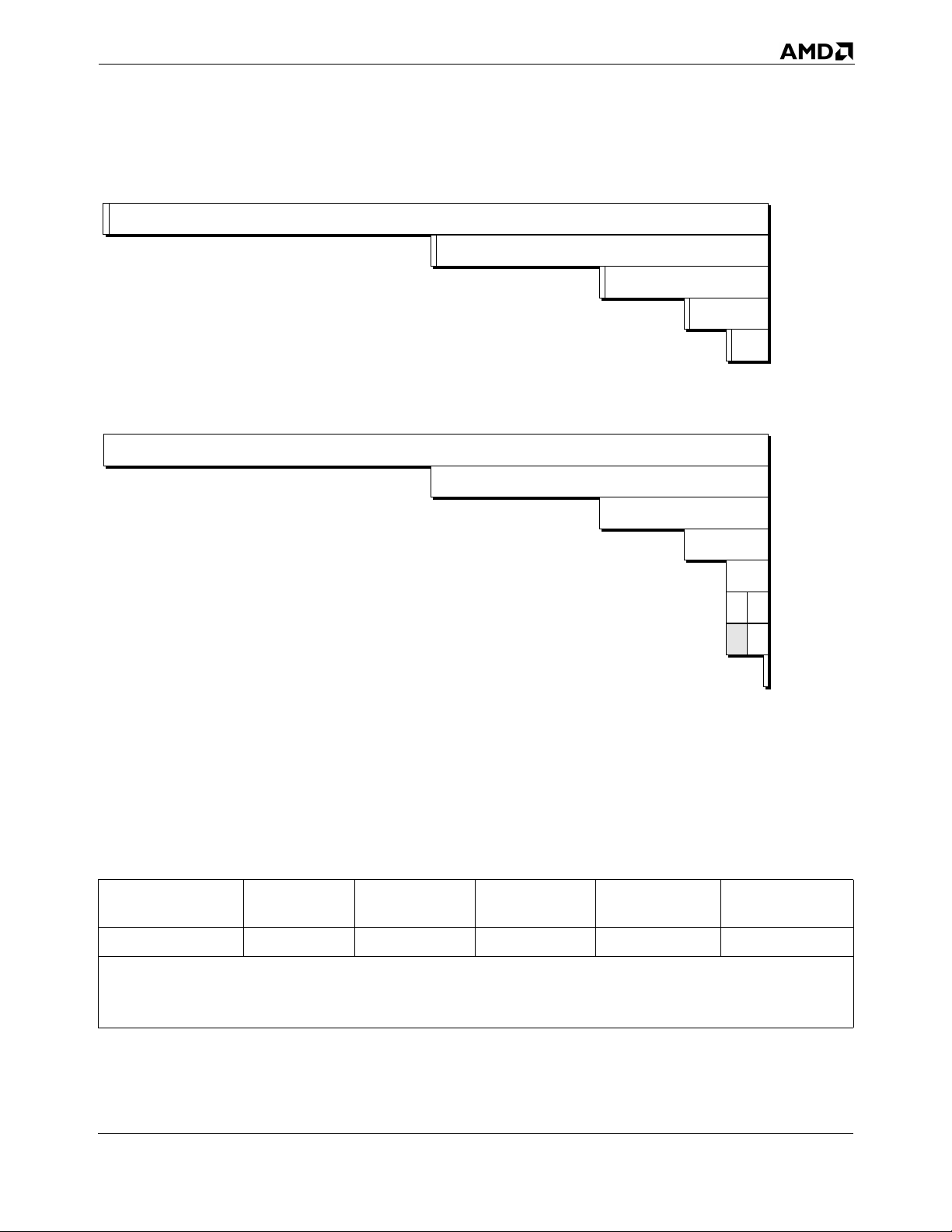
24592—Rev. 3.14—September 2007 AMD64 Technology
127
s
127
Signed Integer
16 bytes (64-bit mode only)
s
63
Unsigned Integer
16 bytes (64-bit mode only)
63
8 bytes (64-bit mode only)
s
31
8 bytes (64-bit mode only)
31
4 bytes
s
15
4 bytes
15
2 bytes
s
70
2 bytes
0
Double
Quadword
Quadword
Doubleword
Word
Byte
0
Double
Quadword
Quadword
Doubleword
Word
Byte
Packed BCD
BCD Digit
73
513-326.eps
Bit
0
Figure 3-6. General-Purpose Data Types
Signed and Unsigned Integers. The architecture supports signed and unsigned 1 byte, 2 bytes, 4
byte and 8 byte integers. The sign bit is stored in the most significant bit.
Table 3-2. Representable Values of General-Purpose Data Types
Data Type Byte Word Doubleword Quadword
1
Signed Integers
Note:
1. The sign bit is the most-significant bit (e.g., bit 7 for a byte, bit 15 for a word, etc.).
2. The double quadword data type is supported in the RDX:RAX registers by the MUL, IMUL, DIV, IDIV, and CQO
instructions.
-27 to +(27 -1) -215 to +(215 -1) -231 to +(231 -1) -263 to +(263 -1) -2
Double
Quadword
127
to +(2
127
2
-1)
General-Purpose Programming 37
Page 70
AMD64 Technology 24592—Rev. 3.14—September 2007
Table 3-2. Representable Values of General-Purpose Data Types (continued)
Data Type Byte Word Doubleword Quadword
8
Unsigned Integers
Packed BCD
Digits
BCD Digit 0 to 9 multiple BCD-digit bytes
Note:
1. The sign bit is the most-significant bit (e.g., bit 7 for a byte, bit 15 for a word, etc.).
2. The double quadword data type is supported in the RDX:RAX registers by the MUL, IMUL, DIV, IDIV, and CQO
instructions.
0 to +2
(0 to 255)
00 to 99 multiple packed BCD-digit bytes
-1
0 to +216-1
(0 to 65,535)
0 to +232-1
(0 to 4.29 x 10
0 to +2
9
(0 to 1.84 x 10
)
64
-1
19
)
Double
Quadword
128
0 to +2
(0 to 3.40 x 10
-1
2
38
Binary-Coded-Decimal (BCD) Digits. BCD digits have values ranging from 0 to 9. These values can
be represented in binary encoding with four bits. For example, 0000b represents the decimal number 0
and 1001b represents the decimal number 9. Values ranging from 1010b to 1111b are invalid for this
data type. Because a byte contains eight bits, two BCD digits can be stored in a single byte. This is
referred to as packed-BCD. If a single BCD digit is stored per byte, it is referred to as unpacked-BCD.
In the x87 floating-point programming environment (described in Section 6, “x87 Floating-Point
Programming,” on page 237) an 80-bit packed BCD data type is also supported, along with
conversions between floating-point and BCD data types, so that data expressed in the BCD format can
be operated on as floating-point values.
)
Integer add, subtract, multiply, and divide instructions can be used to operate on single (unpacked)
BCD digits. The result must be adjusted to produce a correct BCD representation. For unpacked BCD
numbers, the ASCII-adjust instructions are provided to simplify that correction. In the case of division,
the adjustment must be made prior to executing the integer-divide instruction.
Similarly, integer add and subtract instructions can be used to operate on packed-BCD digits. The
result must be adjusted to produce a correct packed-BCD representation. Decimal-adjust instructions
are provided to simplify packed-BCD result corrections.
Strings. Strings are a continuous sequence of a single data type. The string instructions can be used to
operate on byte, word, doubleword, or quadword data types. The maximum length of a string of any
data type is 232–1 bytes, in legacy or compatibility modes, or 264–1 bytes in 64-bit mode. One of the
more common types of strings used by applications are byte data-type strings known as ASCII strings,
which can be used to represent character data.
Bit strings are also supported by instructions that operate specifically on bit strings. In general, bit
strings can start and end at any bit location within any byte, although the BTx bit-string instructions
assume that strings start on a byte boundary. The length of a bit string can range in size from a single
bit up to 232–1 bits, in legacy or compatibility modes, or 264-–1 bits in 64-bit mode.
38 General-Purpose Programming
Page 71
24592—Rev. 3.14—September 2007 AMD64 Technology
3.2.2 Operand Sizes and Overrides
Default Operand Size. In legacy and compatibility modes, the default operand size is either 16 bits
or 32 bits, as determined by the default-size (D) bit in the current code-segment descriptor (for details,
see “Segmented Virtual Memory” in Volume 2). In 64-bit mode, the default operand size for most
instructions is 32 bits.
Application software can override the default operand size by using an operand-size instruction prefix.
Table 3-3 shows the instruction prefixes for operand-size overrides in all operating modes. In 64-bit
mode, the default operand size for most instructions is 32 bits. A REX prefix (see Section 3.5.2, “REX
Prefixes,” on page 74) specifies a 64-bit operand size, and a 66h prefix specifies a 16-bit operand size.
The REX prefix takes precedence over the 66h prefix.
Table 3-3. Operand-Size Overrides
Default
Operating Mode
64-Bit
Mode
Long
Mode
Compatibility
Mode
Legacy Mode
(Protected, Virtual-8086,
or Real Mode)
Note:
1. A “no” indicates that the default operand size is used. An “x” means “don’t care.”
2. Near branches, instructions that implicitly reference the stack pointer, and certain
other instructions default to 64-bit operand size. See “General-Purpose Instructions
in 64-Bit Mode” in Volume 3
Operand
Size (Bits)
2
32
32
16
32
16
Effective
Operand
Size
(Bits)
64 x yes
32 no no
16 yes no
32 no
16 yes
32 yes
16 no
32 no
16 yes
32 yes
16 no
Instruction Prefix
1
66h
Applicable
REX
Not
There are several exceptions to the 32-bit operand-size default in 64-bit mode, including near branches
and instructions that implicitly reference the RSP stack pointer. For example, the near CALL, near
JMP, Jcc, LOOPcc, POP, and PUSH instructions all default to a 64-bit operand size in 64-bit mode.
Such instructions do not need a REX prefix for the 64-bit operand size. For details, see “GeneralPurpose Instructions in 64-Bit Mode” in Volume 3.
Effective Operand Size. The term effective operand size describes the operand size for the current
instruction, after accounting for the instruction’s default operand size and any operand-size override or
REX prefix that is used with the instruction.
General-Purpose Programming 39
Page 72
AMD64 Technology 24592—Rev. 3.14—September 2007
Immediate Operand Size. In legacy mode and compatibility modes, the size of immediate operands
can be 8, 16, or 32 bits, depending on the instruction. In 64-bit mode, the maximum size of an
immediate operand is also 32 bits, except that 64-bit immediates can be copied into a 64-bit GPR using
the MOV instruction.
When the operand size of a MOV instruction is 64 bits, the processor sign-extends immediates to 64
bits before using them. Support for true 64-bit immediates is accomplished by expanding the
semantics of the MOV reg, imm16/32 instructions. In legacy and compatibility modes, these
instructions—opcodes B8h through BFh—copy a 16-bit or 32-bit immediate (depending on the
effective operand size) into a GPR. In 64-bit mode, if the operand size is 64 bits (requires a REX
prefix), these instructions can be used to copy a true 64-bit immediate into a GPR.
3.2.3 Operand Addressing
Operands for general-purpose instructions are referenced by the instruction's syntax or they are
incorporated in the instruction as an immediate value. Referenced operands can be in registers,
memory, or I/O ports.
Register Operands. Most general-purpose instructions that take register operands reference the
general-purpose registers (GPRs). A few general-purpose instructions reference operands in the
RFLAGS register, XMM registers, or MMX™ registers.
The type of register addressed is specified in the instruction syntax. When addressing GPRs or XMM
registers, the REX instruction prefix can be used to access the extended GPRs or XMM registers, as
described in Section 3.5, “Instruction Prefixes,” on page 71.
Memory Operands. Many general-purpose instructions can access operands in memory. Section 2.2,
“Memory Addressing,” on page 14 describes the general methods and conditions for addressing
memory operands.
I/O Ports. Operands in I/O ports are referenced according to the conventions described in Section 3.8,
“Input/Output,” on page 90.
Immediate Operands. In certain instructions, a source operand—called an immediate operand, or
simply immediate—is included as part of the instruction rather than being accessed from a register or
memory location. For details on the size of immediate operands, see “Immediate Operand Size” on
page 40.
3.2.4 Data Alignment
A data access is aligned if its address is a multiple of its operand size, in bytes. The following examples
illustrate this definition:
• Byte accesses are always aligned. Bytes are the smallest addressable parts of memory.
• Word (two-byte) accesses are aligned if their address is a multiple of 2.
• Doubleword (four-byte) accesses are aligned if their address is a multiple of 4.
• Quadword (eight-byte) accesses are aligned if their address is a multiple of 8.
40 General-Purpose Programming
Page 73
24592—Rev. 3.14—September 2007 AMD64 Technology
The AMD64 architecture does not impose data-alignment requirements for accessing data in memory.
However, depending on the location of the misaligned operand with respect to the width of the data bus
and other aspects of the hardware implementation (such as store-to-load forwarding mechanisms), a
misaligned memory access can require more bus cycles than an aligned access. For maximum
performance, avoid misaligned memory accesses.
Performance on many hardware implementations will benefit from observing the following operandalignment and operand-size conventions:
• Avoid misaligned data accesses.
• Maintain consistent use of operand size across all loads and stores. Larger operand sizes
(doubleword and quadword) tend to make more efficient use of the data bus and any dataforwarding features that are implemented by the hardware.
• When using word or byte stores, avoid loading data from the same doubleword of memory, other
than the identical start addresses of the stores.
3.3 Instruction Summary
This section summarizes the functions of the general-purpose instructions. The instructions are
organized by functional group—such as, data-transfer instructions, arithmetic instructions, and so on.
Details on individual instructions are given in the alphabetically organized “General-Purpose
Instruction Reference” in Volume 3.
3.3.1 Syntax
Each instruction has a mnemonic syntax used by assemblers to specify the operation and the operands
to be used for source and destination (result) data. Figure 3-7 shows an example of the mnemonic
syntax for a compare (CMP) instruction. In this example, the CMP mnemonic is followed by two
operands, a 32-bit register or memory operand and an 8-bit immediate operand.
CMP reg/mem32, imm8
Mnemonic
First Source Operand
and Destination Operand
Second Source Operand
513-139.eps
Figure 3-7. Mnemonic Syntax Example
General-Purpose Programming 41
Page 74
AMD64 Technology 24592—Rev. 3.14—September 2007
In most instructions that take two operands, the first (left-most) operand is both a source operand and
the destination operand. The second (right-most) operand serves only as a source. Instructions can
have one or more prefixes that modify default instruction functions or operand properties. These
prefixes are summarized in Section 3.5, “Instruction Prefixes,” on page 71. Instructions that access
64-bit operands in a general-purpose register (GPR) or any of the extended GPR or XMM registers
require a REX instruction prefix.
Unless otherwise stated in this section, the word register means a general-purpose register (GPR).
Several instructions affect the flag bits in the RFLAGS register. “Instruction Effects on RFLAGS” in
Volume 3 summarizes the effects that instructions have on rFLAGS bits.
3.3.2 Data Transfer
The data-transfer instructions copy data between registers and memory.
Move
• MOV—Move
• MOVSX—Move with Sign-Extend
• MOVZX—Move with Zero-Extend
• MOVD—Move Doubleword or Quadword
• MOVNTI—Move Non-Temporal Doubleword or Quadword
MOVx copies a byte, word, doubleword, or quadword from a register or memory location to a register
or memory location. The source and destination cannot both be memory locations. An immediate
constant can be used as a source operand with the MOV instruction. For MOV, the destination must be
of the same size as the source, but the MOVSX and MOVZX instructions copy values of smaller size to
a larger size by using sign-extension or zero-extension. The MOVD instruction copies a doubleword or
quadword between a general-purpose register or memory and an XMM or MMX register.
The MOV instruction is in many aspects similar to the assignment operator in high-level languages.
The simplest example of their use is to initialize variables. To initialize a register to 0, rather than using
a MOV instruction it may be more efficient to use the XOR instruction with identical destination and
source operands.
The MOVNTI instruction stores a doubleword or quadword from a register into memory as “nontemporal” data, which assumes a single access (as opposed to frequent subsequent accesses of
“temporal data”). The operation therefore minimizes cache pollution. The exact method by which
cache pollution is minimized depends on the hardware implementation of the instruction. For further
information, see Section 3.9, “Memory Optimization,” on page 92.
Conditional Move
• CMOVcc—Conditional Move If condition
The CMOVcc instructions conditionally copy a word, doubleword, or quadword from a register or
memory location to a register location. The source and destination must be of the same size.
42 General-Purpose Programming
Page 75
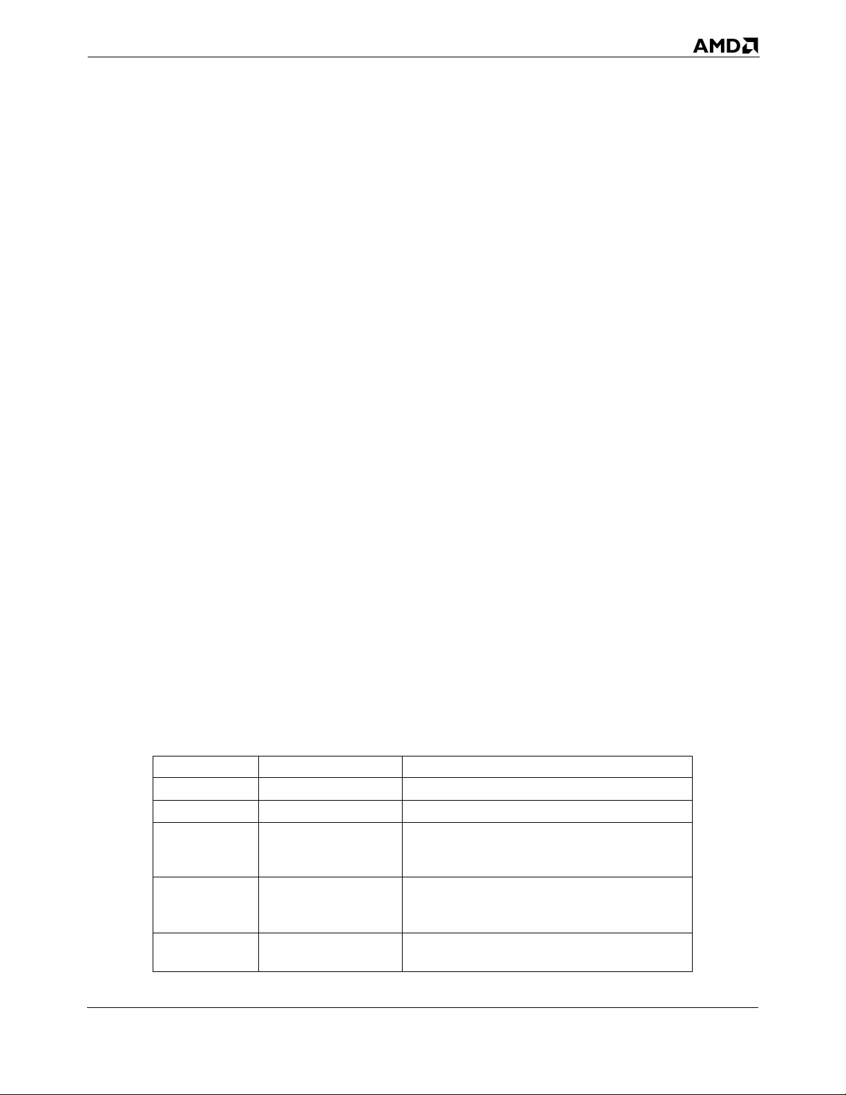
24592—Rev. 3.14—September 2007 AMD64 Technology
The CMOVcc instructions perform the same task as MOV but work conditionally, depending on the
state of status flags in the RFLAGS register. If the condition is not satisfied, the instruction has no
effect and control is passed to the next instruction. The mnemonics of CMOVcc instructions indicate
the condition that must be satisfied. Several mnemonics are often used for one opcode to make the
mnemonics easier to remember. For example, CMOVE (conditional move if equal) and CMOVZ
(conditional move if zero) are aliases and compile to the same opcode. Table 3-4 shows the RFLAGS
values required for each CMOVcc instruction.
In assembly languages, the conditional move instructions correspond to small conditional statements
like:
IF a = b THEN x = y
CMOVcc instructions can replace two instructions—a conditional jump and a move. For example, to
perform a high-level statement like:
IF ECX = 5 THEN EAX = EBX
without a CMOVcc instruction, the code would look like:
cmp ecx, 5 ; test if ecx equals 5
jnz Continue ; test condition and skip if not met
mov eax, ebx ; move
Continue: ; continuation
but with a CMOVcc instruction, the code would look like:
cmp ecx, 5 ; test if ecx equals to 5
cmovz eax, ebx ; test condition and move
Replacing conditional jumps with conditional moves also has the advantage that it can avoid branchprediction penalties that may be caused by conditional jumps.
Support for CMOVcc instructions depends on the processor implementation. To find out if a processor
is able to perform CMOVcc instructions, use the CPUID instruction.
Table 3-4. rFL AGS for CM OVcc Instructions
Mnemonic Required Flag State Description
CMOVO OF = 1 Conditional move if overflow
CMOVNO OF = 0 Conditional move if not overflow
CMOVB
CMOVC
CMOVNAE
CMOVAE
CMOVNB
CMOVNC
CMOVE
CMOVZ
CF = 1
CF = 0
ZF = 1
Conditional move if below
Conditional move if carry
Conditional move if not above or equal
Conditional move if above or equal
Conditional move if not below
Conditional move if not carry
Conditional move if equal
Conditional move if zero
General-Purpose Programming 43
Page 76
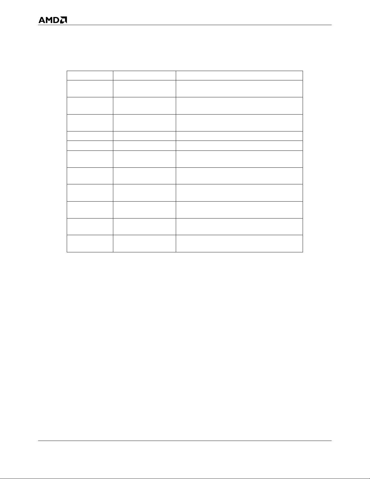
AMD64 Technology 24592—Rev. 3.14—September 2007
Table 3-4. rFL AGS for CM OVcc Instructions (continued)
Mnemonic Required Flag State Description
CMOVNE
CMOVNZ
CMOVBE
CMOVNA
CMOVA
CMOVNBE
CMOVS SF = 1 Conditional move if sign
CMOVNS SF = 0 Conditional move if not sign
CMOVP
CMOVPE
CMOVNP
CMOVPO
CMOVL
CMOVNGE
CMOVGE
CMOVNL
CMOVLE
CMOVNG
CMOVG
CMOVNLE
ZF = 0
CF=1 or ZF=1
CF = 0 and ZF = 0
PF = 1
PF = 0
SF <> OF
SF = OF
ZF = 1 or SF <> OF
ZF=0 and SF=OF
Conditional move if not equal
Conditional move if not zero
Conditional move if below or equal
Conditional move if not above
Conditional move if not below or equal
Conditional move if not below or equal
Conditional move if parity
Conditional move if parity even
Conditional move if not parity
Conditional move if parity odd
Conditional move if less
Conditional move if not greater or equal
Conditional move if greater or equal
Conditional move if not less
Conditional move if less or equal
Conditional move if not greater
Conditional move if greater
Conditional move if not less or equal
Stack Operations
• POP—Pop Stack
• POPA—Pop All to GPR Words
• POPAD—Pop All to GPR Doublewords
• PUSH—Push onto Stack
• PUSHA—Push All GPR Words onto Stack
• PUSHAD—Push All GPR Doublewords onto Stack
• ENTER—Create Procedure Stack Frame
• LEAVE—Delete Procedure Stack Frame
PUSH copies the specified register, memory location, or immediate value to the top of stack. This
instruction decrements the stack pointer by 2, 4, or 8, depending on the operand size, and then copies
the operand into the memory location pointed to by SS:rSP.
POP copies a word, doubleword, or quadword from the memory location pointed to by the SS:rSP
registers (the top of stack) to a specified register or memory location. Then, the rSP register is
incremented by 2, 4, or 8. After the POP operation, rSP points to the new top of stack.
44 General-Purpose Programming
Page 77
24592—Rev. 3.14—September 2007 AMD64 Technology
PUSHA or PUSHAD stores eight word-sized or doubleword-sized registers onto the stack: eAX, eCX,
eDX, eBX, eSP, eBP, eSI and eDI, in that order. The stored value of eSP is sampled at the moment
when the PUSHA instruction started. The resulting stack-pointer value is decremented by 16 or 32.
POPA or POPAD extracts eight word-sized or doubleword-sized registers from the stack: eDI, eSI,
eBP, eSP, eBX, eDX, eCX and eAX, in that order (which is the reverse of the order used in the PUSHA
instruction). The stored eSP value is ignored by the POPA instruction. The resulting stack pointer
value is incremented by 16 or 32.
It is a common practice to use PUSH instructions to pass parameters (via the stack) to functions and
subroutines. The typical instruction sequence used at the beginning of a subroutine looks like:
push ebp ; save current EBP
mov ebp, esp ; set stack frame pointer value
sub esp, N ; allocate space for local variables
The rBP register is used as a stack frame pointer—a base address of the stack area used for parameters
passed to subroutines and local variables. Positive offsets of the stack frame pointed to by rBP provide
access to parameters passed while negative offsets give access to local variables. This technique allows
creating re-entrant subroutines.
The ENTER and LEAVE instructions provide support for procedure calls, and are mainly used in highlevel languages. The ENTER instruction is typically the first instruction of the procedure, and the
LEAVE instruction is the last before the RET instruction.
The ENTER instruction creates a stack frame for a procedure. The first operand, size, specifies the
number of bytes allocated in the stack. The second operand, depth, specifies the number of stack-frame
pointers copied from the calling procedure’s stack (i.e., the nesting level). The depth should be an
integer in the range 0–31.
Typically, when a procedure is called, the stack contains the following four components:
• Parameters passed to the called procedure (created by the calling procedure).
• Return address (created by the CALL instruction).
• Array of stack-frame pointers (pointers to stack frames of procedures with smaller nesting-level
depth) which are used to access the local variables of such procedures.
• Local variables used by the called procedure.
All these data are called the stack frame. The ENTER instruction simplifies management of the last
two components of a stack frame. First, the current value of the rBP register is pushed onto the stack.
The value of the rSP register at that moment is a frame pointer for the current procedure: positive
offsets from this pointer give access to the parameters passed to the procedure, and negative offsets
give access to the local variables which will be allocated later. During procedure execution, the value
of the frame pointer is stored in the rBP register, which at that moment contains a frame pointer of the
calling procedure. This frame pointer is saved in a temporary register. If the depth operand is greater
than one, the array of depth-1 frame pointers of procedures with smaller nesting level is pushed onto
the stack. This array is copied from the stack frame of the calling procedure, and it is addressed by the
General-Purpose Programming 45
Page 78
AMD64 Technology 24592—Rev. 3.14—September 2007
rBP register from the calling procedure. If the depth operand is greater than zero, the saved frame
pointer of the current procedure is pushed onto the stack (forming an array of depth frame pointers).
Finally, the saved value of the frame pointer is copied to the rBP register, and the rSP register is
decremented by the value of the first operand, allocating space for local variables used in the
procedure. See “Stack Operations” on page 44 for a parameter-passing instruction sequence using
PUSH that is equivalent to ENTER.
The LEAVE instruction removes local variables and the array of frame pointers, allocated by the
previous ENTER instruction, from the stack frame. This is accomplished by the following two steps:
first, the value of the frame pointer is copied from the rBP register to the rSP register. This releases the
space allocated by local variables and an array of frame pointers of procedures with smaller nesting
levels. Second, the rBP register is popped from the stack, restoring the previous value of the frame
pointer (or simply the value of the rBP register, if the depth operand is zero). Thus, the LEAVE
instruction is equivalent to the following code:
mov rSP, rBP
pop rBP
3.3.3 Data Conversion
The data-conversion instructions perform various transformations of data, such as operand-size
doubling by sign extension, conversion of little-endian to big-endian format, extraction of sign masks,
searching a table, and support for operations with decimal numbers.
Sign Extension
• CBW—Convert Byte to Word
• CWDE—Convert Word to Doubleword
• CDQE—Convert Doubleword to Quadword
• CWD—Convert Word to Doubleword
• CDQ—Convert Doubleword to Quadword
• CQO—Convert Quadword to Octword
The CBW, CWDE, and CDQE instructions sign-extend the AL, AX, or EAX register to the upper half
of the AX, EAX, or RAX register, respectively. By doing so, these instructions create a double-sized
destination operand in rAX that has the same numerical value as the source operand. The CBW,
CWDE, and CDQE instructions have the same opcode, and the action taken depends on the effective
operand size.
The CWD, CDQ and CQO instructions sign-extend the AX, EAX, or RAX register to all bit positions
of the DX, EDX, or RDX register, respectively. By doing so, these instructions create a double-sized
destination operand in rDX:rAX that has the same numerical value as the source operand. The CWD,
CDQ, and CQO instructions have the same opcode, and the action taken depends on the effective
operand size.
46 General-Purpose Programming
Page 79
24592—Rev. 3.14—September 2007 AMD64 Technology
Flags are not affected by these instructions. The instructions can be used to prepare an operand for
signed division (performed by the IDIV instruction) by doubling its storage size.
Extract Sign Mask
• MOVMSKPS—Extract Packed Single-Precision Floating-Point Sign Mask
• MOVMSKPD—Extract Packed Double-Precision Floating-Point Sign Mask
The MOVMSKPS instruction moves the sign bits of four packed single-precision floating-point values
in an XMM register to the four low-order bits of a general-purpose register, with zero-extension.
MOVMSKPD does a similar operation for two packed double-precision floating-point values: it
moves the two sign bits to the two low-order bits of a general-purpose register, with zero-extension.
The result of either instruction is a sign-bit mask.
Translate
• XLAT—Translate Table Index
The XLAT instruction replaces the value stored in the AL register with a table element. The initial
value in AL serves as an unsigned index into the table, and the start (base) of table is specified by the
DS:rBX registers (depending on the effective address size).
This instruction is not recommended. The following instruction serves to replace it:
MOV AL,[rBX + AL]
ASCII Adjust.
• AAA—ASCII Adjust After Addition
• AAD—ASCII Adjust Before Division
• AAM—ASCII Adjust After Multiply
• AAS—ASCII Adjust After Subtraction
The AAA, AAD, AAM, and AAS instructions perform corrections of arithmetic operations with nonpacked BCD values (i.e., when the decimal digit is stored in a byte register). There are no instructions
which directly operate on decimal numbers (either packed or non-packed BCD). However, the ASCIIadjust instructions correct decimal-arithmetic results. These instructions assume that an arithmetic
instruction, such as ADD, was performed on two BCD operands, and that the result was stored in the
AL or AX register. This result can be incorrect or it can be a non-BCD value (for example, when a
decimal carry occurs). After executing the proper ASCII-adjust instruction, the AX register contains a
correct BCD representation of the result. (The AAD instruction is an exception to this, because it
should be applied before a DIV instruction, as explained below). All of the ASCII-adjust instructions
are able to operate with multiple-precision decimal values.
AAA should be applied after addition of two non-packed decimal digits. AAS should be applied after
subtraction of two non-packed decimal digits. AAM should be applied after multiplication of two non-
packed decimal digits. AAD should be applied before the division of two non-packed decimal
numbers.
General-Purpose Programming 47
Page 80
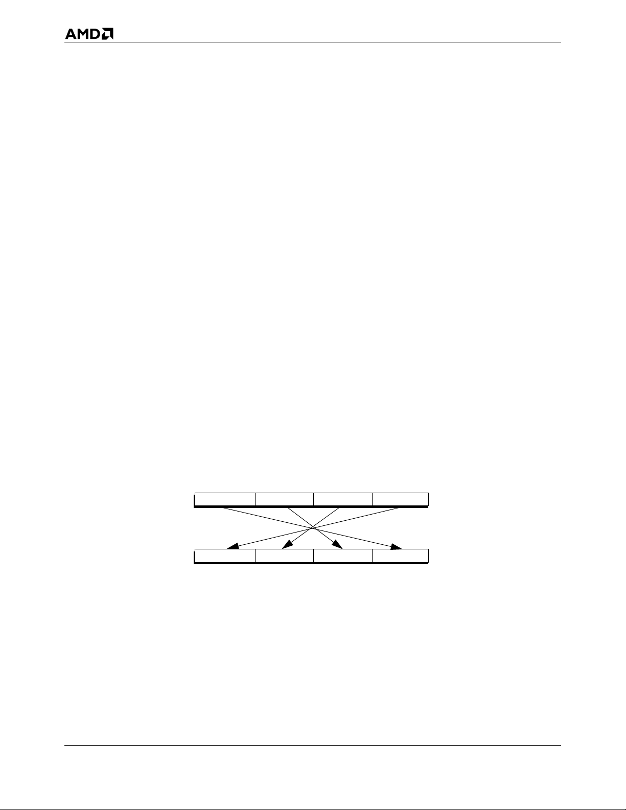
AMD64 Technology 24592—Rev. 3.14—September 2007
Although the base of the numeration for ASCII-adjust instructions is assumed to be 10, the AAM and
AAD instructions can be used to correct multiplication and division with other bases.
BCD Adjust
• DAA—Decimal Adjust after Addition
• DAS—Decimal Adjust after Subtraction
The DAA and DAS instructions perform corrections of addition and subtraction operations on packed
BCD values. (Packed BCD values have two decimal digits stored in a byte register, with the higher
digit in the higher four bits, and the lower one in the lower four bits.) There are no instructions for
correction of multiplication and division with packed BCD values.
DAA should be applied after addition of two packed-BCD numbers. DAS should be applied after
subtraction of two packed-BCD numbers.
DAA and DAS can be used in a loop to perform addition or subtraction of two multiple-precision
decimal numbers stored in packed-BCD format. Each loop cycle would operate on corresponding
bytes (containing two decimal digits) of operands.
Endian Conversion
• BSWAP—Byte Swap
The BSWAP instruction changes the byte order of a doubleword or quadword operand in a register, as
shown in Figure 3-8. In a doubleword, bits 7–0 are exchanged with bits 31–24, and bits 15–8 are
exchanged with bits 23–16. In a quadword, bits 7–0 are exchanged with bits 63–56, bits 15–8 with bits
55–48, bits 23–16 with bits 47–40, and bits 31–24 with bits 39–32. See the following illustration.
07815162331 24
07815162331 24
Figure 3-8. BSWAP Doubleword Exchange
A second application of the BSWAP instruction to the same operand restores its original value. The
result of applying the BSWAP instruction to a 16-bit register is undefined. To swap bytes of a 16-bit
register, use the XCHG instruction.
The BSWAP instruction is used to convert data between little-endian and big-endian byte order.
48 General-Purpose Programming
Page 81
24592—Rev. 3.14—September 2007 AMD64 Technology
3.3.4 Load Segment Registers
These instructions load segment registers.
• LDS, LES, LFS, LGS, LSS—Load Far Pointer
• MOV segReg—Move Segment Register
• POP segReg—Pop Stack Into Segment Register
The LDS, LES, LFD, LGS, and LSS instructions atomically load the two parts of a far pointer into a
segment register and a general-purpose register. A far pointer is a 16-bit segment selector and a 16-bit
or 32-bit offset. The load copies the segment-selector portion of the pointer from memory into the
segment register and the offset portion of the pointer from memory into a general-purpose register.
The effective operand size determines the size of the offset loaded by the LDS, LES, LFD, LGS, and
LSS instructions. The instructions load not only the software-visible segment selector into the segment
register, but they also cause the hardware to load the associated segment-descriptor information into
the software-invisible (hidden) portion of that segment register.
The MOV segReg and POP segReg instructions load a segment selector from a general-purpose
register or memory (for MOV segReg) or from the top of the stack (for POP segReg) to a segment
register. These instructions not only load the software-visible segment selector into the segment
register but also cause the hardware to load the associated segment-descriptor information into the
software-invisible (hidden) portion of that segment register.
In 64-bit mode, the POP DS, POP ES, and POP SS instructions are invalid.
3.3.5 Load Effective Address
• LEA—Load Effective Address
The LEA instruction calculates and loads the effective address (offset within a given segment) of a
source operand and places it in a general-purpose register.
LEA is related to MOV, which copies data from a memory location to a register, but LEA takes the
address of the source operand, whereas MOV takes the contents of the memory location specified by
the source operand. In the simplest cases, LEA can be replaced with MOV. For example:
lea eax, [ebx]
has the same effect as:
mov eax, ebx
However, LEA allows software to use any valid addressing mode for the source operand. For example:
lea eax, [ebx+edi]
loads the sum of EBX and EDI registers into the EAX register. This could not be accomplished by a
single MOV instruction.
General-Purpose Programming 49
Page 82
AMD64 Technology 24592—Rev. 3.14—September 2007
LEA has a limited capability to perform multiplication of operands in general-purpose registers using
scaled-index addressing. For example:
lea eax, [ebx+ebx*8]
loads the value of the EBX register, multiplied by 9, into the EAX register.
3.3.6 Arithmetic
The arithmetic instructions perform basic arithmetic operations, such as addition, subtraction,
multiplication, and division on integer operands.
Add and Subtract
• ADC—Add with Carry
• ADD—Signed or Unsigned Add
• SBB—Subtract with Borrow
• SUB—Subtract
• NEG—Two’s Complement Negation
The ADD instruction performs addition of two integer operands. There are opcodes that add an
immediate value to a byte, word, doubleword, or quadword register or a memory location. In these
opcodes, if the size of the immediate is smaller than that of the destination, the immediate is first signextended to the size of the destination operand. The arithmetic flags (OF, SF, ZF, AF, CF, PF) are set
according to the resulting value of the destination operand.
The ADC instruction performs addition of two integer operands, plus 1 if the carry flag (CF) is set.
The SUB instruction performs subtraction of two integer operands.
The SBB instruction performs subtraction of two integer operands, and it also subtracts an additional 1
if the carry flag is set.
The ADC and SBB instructions simplify addition and subtraction of multiple-precision integer
operands, because they correctly handle carries (and borrows) between parts of a multiple-precision
operand.
The NEG instruction performs negation of an integer operand. The value of the operand is replaced
with the result of subtracting the operand from zero.
Multiply and Divide
• MUL—Multiply Unsigned
• IMUL—Signed Multiply
• DIV—Unsigned Divide
• IDIV—Signed Divide
50 General-Purpose Programming
Page 83
24592—Rev. 3.14—September 2007 AMD64 Technology
The MUL instruction performs multiplication of unsigned integer operands. The size of operands can
be byte, word, doubleword, or quadword. The product is stored in a destination which is double the
size of the source operands (multiplicand and factor).
The MUL instruction's mnemonic has only one operand, which is a factor. The multiplicand operand is
always assumed to be an accumulator register. For byte-sized multiplies, AL contains the multiplicand,
and the result is stored in AX. For word-sized, doubleword-sized, and quadword-sized multiplies, rAX
contains the multiplicand, and the result is stored in rDX and rAX.
The IMUL instruction performs multiplication of signed integer operands. There are forms of the
IMUL instruction with one, two, and three operands, and it is thus more powerful than the MUL
instruction. The one-operand form of the IMUL instruction behaves similarly to the MUL instruction,
except that the operands and product are signed integer values. In the two-operand form of IMUL, the
multiplicand and product use the same register (the first operand), and the factor is specified in the
second operand. In the three-operand form of IMUL, the product is stored in the first operand, the
multiplicand is specified in the second operand, and the factor is specified in the third operand.
The DIV instruction performs division of unsigned integers. The instruction divides a double-sized
dividend in AH:AL or rDX:rAX by the divisor specified in the operand of the instruction. It stores the
quotient in AL or rAX and the remainder in AH or rDX.
The IDIV instruction performs division of signed integers. It behaves similarly to DIV, with the
exception that the operands are treated as signed integer values.
Division is the slowest of all integer arithmetic operations and should be avoided wherever possible.
One possibility for improving performance is to replace division with multiplication, such as by
replacing i/j/k with i/(j*k). This replacement is possible if no overflow occurs during the computation
of the product. This can be determined by considering the possible ranges of the divisors.
Increment and Decrement
• DEC—Decrement by 1
• INC—Increment by 1
The INC and DEC instructions are used to increment and decrement, respectively, an integer operand
by one. For both instructions, an operand can be a byte, word, doubleword, or quadword register or
memory location.
These instructions behave in all respects like the corresponding ADD and SUB instructions, with the
second operand as an immediate value equal to 1. The only exception is that the carry flag (CF) is not
affected by the INC and DEC instructions.
Apart from their obvious arithmetic uses, the INC and DEC instructions are often used to modify
addresses of operands. In this case it can be desirable to preserve the value of the carry flag (to use it
later), so these instructions do not modify the carry flag.
General-Purpose Programming 51
Page 84
AMD64 Technology 24592—Rev. 3.14—September 2007
3.3.7 Rotate and Shift
The rotate and shift instructions perform cyclic rotation or non-cyclic shift, by a given number of bits
(called the count), in a given byte-sized, word-sized, doubleword-sized or quadword-sized operand.
When the count is greater than 1, the result of the rotate and shift instructions can be considered as an
iteration of the same 1-bit operation by count number of times. Because of this, the descriptions below
describe the result of 1-bit operations.
The count can be 1, the value of the CL register, or an immediate 8-bit value. To avoid redundancy and
make rotation and shifting quicker, the count is masked to the 5 or 6 least-significant bits, depending
on the effective operand size, so that its value does not exceed 31 or 63 before the rotation or shift takes
place.
Rotate
• RCL—Rotate Through Carry Left
• RCR—Rotate Through Carry Right
• ROL—Rotate Left
• ROR—Rotate Right
The RCx instructions rotate the bits of the first operand to the left or right by the number of bits
specified by the source (count) operand. The bits rotated out of the destination operand are rotated into
the carry flag (CF) and the carry flag is rotated into the opposite end of the first operand.
The ROx instructions rotate the bits of the first operand to the left or right by the number of bits
specified by the source operand. Bits rotated out are rotated back in at the opposite end. The value of
the CF flag is determined by the value of the last bit rotated out. In single-bit left-rotates, the overflow
flag (OF) is set to the XOR of the CF flag after rotation and the most-significant bit of the result. In
single-bit right-rotates, the OF flag is set to the XOR of the two most-significant bits. Thus, in both
cases, the OF flag is set to 1 if the single-bit rotation changed the value of the most-significant bit (sign
bit) of the operand. The value of the OF flag is undefined for multi-bit rotates.
Bit-rotation instructions provide many ways to reorder bits in an operand. This can be useful, for
example, in character conversion, including cryptography techniques.
Shift
• SAL—Shift Arithmetic Left
• SAR—Shift Arithmetic Right
• SHL—Shift Left
• SHR—Shift Right
• SHLD—Shift Left Double
• SHRD—Shift Right Double
52 General-Purpose Programming
Page 85
24592—Rev. 3.14—September 2007 AMD64 Technology
The SHx instructions (including SHxD) perform shift operations on unsigned operands. The SAx
instructions operate with signed operands.
SHL and SAL instructions effectively perform multiplication of an operand by a power of 2, in which
case they work as more-efficient alternatives to the MUL instruction. Similarly, SHR and SAR
instructions can be used to divide an operand (signed or unsigned, depending on the instruction used)
by a power of 2.
Although the SAR instruction divides the operand by a power of 2, the behavior is different from the
IDIV instruction. For example, shifting –11 (FFFFFFF5h) by two bits to the right (i.e. divide –11 by
4), gives a result of FFFFFFFDh, or –3, whereas the IDIV instruction for dividing –11 by 4 gives a
result of –2. This is because the IDIV instruction rounds off the quotient to zero, whereas the SAR
instruction rounds off the remainder to zero for positive dividends, and to negative infinity for negative
dividends. This means that, for positive operands, SAR behaves like the corresponding IDIV
instruction, and for negative operands, it gives the same result if and only if all the shifted-out bits are
zeroes, and otherwise the result is smaller by 1.
The SAR instruction treats the most-significant bit (msb) of an operand in a special way: the msb (the
sign bit) is not changed, but is copied to the next bit, preserving the sign of the result. The leastsignificant bit (lsb) is shifted out to the CF flag. In the SAL instruction, the msb is shifted out to CF
flag, and the lsb is cleared to 0.
The SHx instructions perform logical shift, i.e. without special treatment of the sign bit. SHL is the
same as SAL (in fact, their opcodes are the same). SHR copies 0 into the most-significant bit, and
shifts the least-significant bit to the CF flag.
The SHxD instructions perform a double shift. These instructions perform left and right shift of the
destination operand, taking the bits to copy into the most-significant bit (for the SHRD instruction) or
into the least-significant bit (for the SHLD instruction) from the source operand. These instructions
behave like SHx, but use bits from the source operand instead of zero bits to shift into the destination
operand. The source operand is not changed.
3.3.8 Compare and Test
The compare and test instructions perform arithmetic and logical comparison of operands and set
corresponding flags, depending on the result of comparison. These instruction are used in conjunction
with conditional instructions such as Jcc or SETcc to organize branching and conditionally executing
blocks in programs. Assembler equivalents of conditional operators in high-level languages
(do…while, if…then…else, and similar) also include compare and test instructions.
Compare
• CMP—Compare
The CMP instruction performs subtraction of the second operand (source) from the first operand
(destination), like the SUB instruction, but it does not store the resulting value in the destination
operand. It leaves both operands intact. The only effect of the CMP instruction is to set or clear the
arithmetic flags (OF, SF, ZF, AF, CF, PF) according to the result of subtraction.
General-Purpose Programming 53
Page 86
AMD64 Technology 24592—Rev. 3.14—September 2007
The CMP instruction is often used together with the conditional jump instructions (Jcc), conditional
SET instructions (SETcc) and other instructions such as conditional loops (LOOPcc) whose behavior
depends on flag state.
Test
• TEST—Test Bits
The TEST instruction is in many ways similar to the AND instruction: it performs logical conjunction
of the corresponding bits of both operands, but unlike the AND instruction it leaves the operands
unchanged. The purpose of this instruction is to update flags for further testing.
The TEST instruction is often used to test whether one or more bits in an operand are zero. In this case,
one of the instruction operands would contain a mask in which all bits are cleared to zero except the
bits being tested. For more advanced bit testing and bit modification, use the BTx instructions.
Bit Scan
• BSF—Bit Scan Forward
• BSR—Bit Scan Reverse
The BSF and BSR instructions search a source operand for the least-significant (BSF) or mostsignificant (BSR) bit that is set to 1. If a set bit is found, its bit index is loaded into the destination
operand, and the zero flag (ZF) is set. If no set bit is found, the zero flag is cleared and the contents of
the destination are undefined.
Population and Leading Zero Counts
• POPCNT—Bit Population Count
• LZCNT—Count Leading Zeros
The POPCNT instruction counts the number of bits having a value of 1 in the source operand and
places the total in the destination register, while the LZCNT instruction counts the number of leading
zero bits in a general purpose register or memory source operand.
Bit Test
• BT—Bit Test
• BTC—Bit Test and Complement
• BTR—Bit Test and Reset
• BTS—Bit Test and Set
The BTx instructions copy a specified bit in the first operand to the carry flag (CF) and leave the source
bit unchanged (BT), or complement the source bit (BTC), or clear the source bit to 0 (BTR), or set the
source bit to 1 (BTS).
These instructions are useful for implementing semaphore arrays. Unlike the XCHG instruction, the
BTx instructions set the carry flag, so no additional test or compare instruction is needed. Also,
54 General-Purpose Programming
Page 87
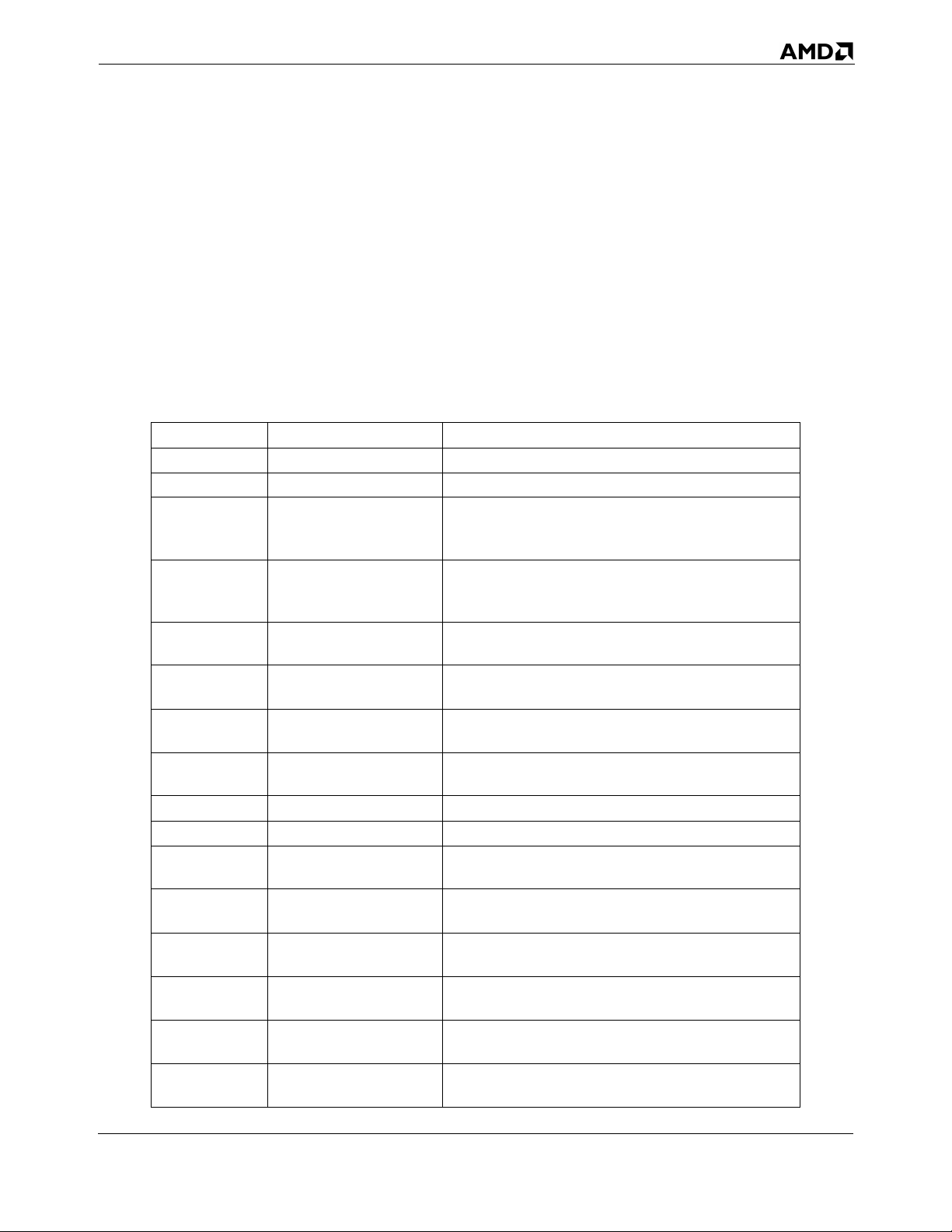
24592—Rev. 3.14—September 2007 AMD64 Technology
because these instructions operate directly on bits rather than larger data types, the semaphore arrays
can be smaller than is possible when using XCHG. In such semaphore applications, bit-test
instructions should be preceded by the LOCK prefix.
Set Byte on Condition
• SETcc—Set Byte if condition
The SETcc instructions store a 1 or 0 value to their byte operand depending on whether their condition
(represented by certain rFLAGS bits) is true or false, respectively. Table 3-5 shows the rFLAGS values
required for each SETcc instruction.
Table 3-5. rFLAGS for SETcc Instructions
Mnemonic Required Flag State Description
SETO OF = 1 Set byte if overflow
SETNO OF = 0 Set byte if not overflow
SETB
SETC
SETNAE
SETAE
SETNB
SETNC
SETE
SET
Z
SETNE
SETNZ
SETBE
SETNA
SETA
SETNBE
SETS SF = 1 Set byte if sign
SETNS SF = 0 Set byte if not sign
SETP
SETPE
SETNP
SETPO
SETL
SETNGE
SETGE
SETNL
SETLE
SETNG
SETG
SETNLE
CF = 1
CF = 0
ZF = 1
ZF = 0
CF = 1 or ZF = 1
CF = 0 and ZF = 0
PF = 1
PF = 0
SF <> OF
SF = OF
ZF = 1 or SF <> OF
ZF = 0 and SF = OF
Set byte if below
Set byte if carry
Set byte if not above or equal (unsigned operands)
Set byte if above or equal
Set byte if not below
Set byte if not carry (unsigned operands)
Set byte if equal
Set byte if zero
Set byte if not equal
Set byte if not zero
Set byte if below or equal
Set byte if not above (unsigned operands)
Set byte if not below or equal
Set byte if not below or equal (unsigned operands)
Set byte if parity
Set byte if parity even
Set byte if not parity
Set byte if parity odd
Set byte if less
Set byte if not greater or equal (signed operands)
Set byte if greater or equal
Set byte if not less (signed operands)
Set byte if less or equal
Set byte if not greater (signed operands)
Set byte if greater
Set byte if not less or equal (signed operands)
General-Purpose Programming 55
Page 88
AMD64 Technology 24592—Rev. 3.14—September 2007
SETcc instructions are often used to set logical indicators. Like CMOVcc instructions (page 42),
SETcc instructions can replace two instructions—a conditional jump and a move. Replacing
conditional jumps with conditional sets can help avoid branch-prediction penalties that may be caused
by conditional jumps.
If the logical value True (logical 1) is represented in a high-level language as an integer with all bits set
to 1, software can accomplish such representation by first executing the opposite SETcc instruction—
for example, the opposite of SETZ is SETNZ—and then decrementing the result.
Bounds
• BOUND—Check Array Bounds
The BOUND instruction checks whether the value of the first operand, a signed integer index into an
array, is within the minimal and maximal bound values pointed to by the second operand. The values
of array bounds are often stored at the beginning of the array. If the bounds of the range are exceeded,
the processor generates a bound-range exception.
The primary disadvantage of using the BOUND instruction is its use of the time-consuming exception
mechanism to signal a failure of the bounds test.
3.3.9 Logical
The logical instructions perform bitwise operations.
• AND—Logical AND
• OR—Logical OR
• XOR—Exclusive OR
• NOT—One’s Complement Negation
The AND, OR, and XOR instructions perform their respective logical operations on the corresponding
bits of both operands and store the result in the first operand. The CF flag and OF flag are cleared to 0,
and the ZF flag, SF flag, and PF flag are set according to the resulting value of the first operand.
The NOT instruction performs logical inversion of all bits of its operand. Each zero bit becomes one
and vice versa. All flags remain unchanged.
Apart from performing logical operations, AND and OR can test a register for a zero or non-zero
value, sign (negative or positive), and parity status of its lowest byte. To do this, both operands must be
the same register. The XOR instruction with two identical operands is an efficient way of loading the
value 0 into a register.
3.3.10 String
The string instructions perform common string operations such as copying, moving, comparing, or
searching strings. These instructions are widely used for processing text.
56 General-Purpose Programming
Page 89
24592—Rev. 3.14—September 2007 AMD64 Technology
Compare Strings
• CMPS—Compare Strings
• CMPSB—Compare Strings by Byte
• CMPSW—Compare Strings by Word
• CMPSD—Compare Strings by Doubleword
• CMPSQ—Compare Strings by Quadword
The CMPSx instructions compare the values of two implicit operands of the same size located at
seg:[rSI] and ES:[rDI]. After the copy, both the rSI and rDI registers are auto-incremented (if the DF
flag is 0) or auto-decremented (if the DF flag is 1).
Scan String
• SCAS—Scan String
• SCASB—Scan String as Bytes
• SCASW—Scan String as Words
• SCASD—Scan String as Doubleword
• SCASQ—Scan String as Quadword
The SCASx instructions compare the values of a memory operands in ES:rDI to a value of the same
size in the AL/rAX register. Bits in rFLAGS are set to indicate the outcome of the comparison. After
the comparison, the rDI register is auto-incremented (if the DF flag is 0) or auto-decremented (if the
DF flag is 1).
Move String
• MOVS—Move String
• MOVSB—Move String Byte
• MOVSW—Move String Word
• MOVSD—Move String Doubleword
• MOVSQ—Move String Quadword
The MOVSx instructions copy an operand from the memory location seg:[rSI] to the memory location
ES:[rDI]. After the copy, both the rSI and rDI registers are auto-incremented (if the DF flag is 0) or
auto-decremented (if the DF flag is 1).
Load String
• LODS—Load String
• LODSB—Load String Byte
• LODSW—Load String Word
• LODSD—Load String Doubleword
• LODSQ—Load String Quadword
General-Purpose Programming 57
Page 90
AMD64 Technology 24592—Rev. 3.14—September 2007
The LODSx instructions load a value from the memory location seg:[rSI] to the accumulator register
(AL or rAX). After the load, the rSI register is auto-incremented (if the DF flag is 0) or autodecremented (if the DF flag is 1).
Store String
• STOS—Store String
• STOSB—Store String Bytes
• STOSW—Store String Words
• STOSD—Store String Doublewords
• STOSQ—Store String Quadword
The STOSx instructions copy the accumulator register (AL or rAX) to a memory location ES:[rDI].
After the copy, the rDI register is auto-incremented (if the DF flag is 0) or auto-decremented (if the DF
flag is 1).
3.3.11 Control Transfer
Control-transfer instructions, or branches, are used to iterate through loops and move through
conditional program logic.
Jump
• JMP—Jump
JMP performs an unconditional jump to the specified address. There are several ways to specify the
target address.
• Relative Short Jump and Relative Near Jump—The target address is determined by adding an 8-bit
(short jump) or 16-bit or 32-bit (near jump) signed displacement to the rIP of the instruction
following the JMP. The jump is performed within the current code segment (CS).
• Register-Indirect and Memory-Indirect Near Jump—The target rIP value is contained in a register
or in a memory location. The jump is performed within the current CS.
• Direct Far Jump—For all far jumps, the target address is outside the current code segment. Here,
the instruction specifies the 16-bit target-address code segment and the 16-bit or 32-bit offset as an
immediate value. The direct far jump form is invalid in 64-bit mode.
• Memory-Indirect Far Jump—For this form, the target address (CS:rIP) is in a address outside the
current code segment. A 32-bit or 48-bit far pointer in a specified memory location points to the
target address.
The size of the target rIP is determined by the effective operand size for the JMP instruction.
For far jumps, the target selector can specify a code-segment selector, in which case it is loaded into
CS, and a 16-bit or 32-bit target offset is loaded into rIP. The target selector can also be a call-gate
selector or a task-state-segment (TSS) selector, used for performing task switches. In these cases, the
58 General-Purpose Programming
Page 91
24592—Rev. 3.14—September 2007 AMD64 Technology
target offset of the JMP instruction is ignored, and the new values loaded into CS and rIP are taken
from the call gate or from the TSS.
Conditional Jump
• Jcc—Jump if condition
Conditional jump instructions jump to an instruction specified by the operand, depending on the state
of flags in the rFLAGS register. The operands specifies a signed relative offset from the current
contents of the rIP. If the state of the corresponding flags meets the condition, a conditional jump
instruction passes control to the target instruction, otherwise control is passed to the instruction
following the conditional jump instruction. The flags tested by a specific Jcc instruction depend on the
opcode. In several cases, multiple mnemonics correspond to one opcode.
Table 3-6 shows the rFLAGS values required for each Jcc instruction.
Table 3-6. rFLAGS for Jcc Instructions
Mnemonic Required Flag State Description
JO OF = 1 Jump near if overflow
JNO OF = 0 Jump near if not overflow
JB
JC
JNAE
JNB
JNC
JAE
JZ
JE
JNZ
JNE
JNA
JBE
JNBE
JA
JS SF = 1 Jump near if sign
JNS SF = 0 Jump near if not sign
JP
JPE
JNP
JPO
JL
JNGE
CF = 1
CF = 0
ZF = 1
ZF = 0
CF=1 or ZF=1
CF = 0 and ZF = 0
PF = 1
PF = 0
SF <> OF
Jump near if below
Jump near if carry
Jump near if not above or equal
Jump near if not below
Jump near if not carry
Jump near if above or equal
Jump near if 0
Jump near if equal
Jump near if not zero
Jump near if not equal
Jump near if not above
Jump near if below or equal
Jump near if not below or equal
Jump near if above
Jump near if parity
Jump near if parity even
Jump near if not parity
Jump near if parity odd
Jump near if less
Jump near if not greater or equal
General-Purpose Programming 59
Page 92
AMD64 Technology 24592—Rev. 3.14—September 2007
Table 3-6. rFLAGS for Jcc Instructions (continued)
Mnemonic Required Flag State Description
JGE
JNL
JNG
JLE
JNLE
JG
SF = OF
ZF = 1 or SF <> OF
ZF=0 and SF=OF
Jump near if greater or equal
Jump near if not less
Jump near if not greater
Jump near if less or equal
Jump near if not less or equal
Jump near if greater
Unlike the unconditional jump (JMP), conditional jump instructions have only two forms—near
conditional jumps and short conditional jumps. To create a far-conditional-jump code sequence
corresponding to a high-level language statement like:
IF A = B THEN GOTO FarLabel
where FarLabel is located in another code segment, use the opposite condition in a conditional short
jump before the unconditional far jump. For example:
cmp A,B ; compare operands
jne NextInstr ; continue program if not equal
jmp far ptr WhenNE ; far jump if operands are equal
NextInstr: ; continue program
Three special conditional jump instructions use the rCX register instead of flags. The JCXZ, JECXZ,
and JRCXZ instructions check the value of the CX, ECX, and RCX registers, respectively, and pass
control to the target instruction when the value of rCX register reaches 0. These instructions are often
used to control safe cycles, preventing execution when the value in rCX reaches 0.
Loop
• LOOPcc—Loop if condition
The LOOPcc instructions include LOOPE, LOOPNE, LOOPNZ, and LOOPZ. These instructions
decrement the rCX register by 1 without changing any flags, and then check to see if the loop condition
is met. If the condition is met, the program jumps to the specified target code.
LOOPE and LOOPZ are synonyms. Their loop condition is met if the value of the rCX register is nonzero and the zero flag (ZF) is set to 1 when the instruction starts. LOOPNE and LOOPNZ are also
synonyms. Their loop condition is met if the value of the rCX register is non-zero and the ZF flag is
cleared to 0 when the instruction starts. LOOP, unlike the other mnemonics, does not check the ZF
flag. Its loop condition is met if the value of the rCX register is non-zero.
Call
• CALL—Procedure Call
The CALL instruction performs a call to a procedure whose address is specified in the operand. The
return address is placed on the stack by the CALL, and points to the instruction immediately following
60 General-Purpose Programming
Page 93
24592—Rev. 3.14—September 2007 AMD64 Technology
the CALL. When the called procedure finishes execution and is exited using a return instruction,
control is transferred to the return address saved on the stack.
The CALL instruction has the same forms as the JMP instruction, except that CALL lacks the shortrelative (1-byte offset) form.
• Relative Near Call—These specify an offset relative to the instruction following the CALL
instruction. The operand is an immediate 16-bit or 32-bit offset from the called procedure, within
the same code segment.
• Register-Indirect and Memory-Indirect Near Call—These specify a target address contained in a
register or memory location.
• Direct Far Call—These specify a target address outside the current code segment. The address is
pointed to by a 32-bit or 48-bit far-pointer specified by the instruction, which consists of a 16-bit
code selector and a 16-bit or 32-bit offset. The direct far call form is invalid in 64-bit mode.
• Memory-Indirect Far Call—These specify a target address outside the current code segment. The
address is pointed to by a 32-bit or 48-bit far pointer in a specified memory location.
The size of the rIP is in all cases determined by the operand-size attribute of the CALL instruction.
CALLs push the return address to the stack. The data pushed on the stack depends on whether a near or
far call is performed, and whether a privilege change occurs. See Section 3.7.5, “Procedure Calls,” on
page 79 for further information.
For far CALLs, the selector portion of the target address can specify a code-segment selector (in which
case the selector is loaded into the CS register), or a call-gate selector, (used for calls that change
privilege level), or a task-state-segment (TSS) selector (used for task switches). In the latter two cases,
the offset portion of the CALL instruction’s target address is ignored, and the new values loaded into
CS and rIP are taken from the call gate or TSS.
Return
• RET—Return from Call
The RET instruction returns from a procedure originally called using the CALL instruction. CALL
places a return address (which points to the instruction following the CALL) on the stack. RET takes
the return address from the stack and transfers control to the instruction located at that address.
Like CALL instructions, RET instructions have both a near and far form. An optional immediate
operand for the RET specifies the number of bytes to be popped from the procedure stack for
parameters placed on the stack. See Section 3.7.6, “Returning from Procedures,” on page 81 for
additional information.
Interrupts and Exceptions.
• INT—Interrupt to Vector Number
• INTO—Interrupt to Overflow Vector
• IRET—Interrupt Return Word
General-Purpose Programming 61
Page 94
AMD64 Technology 24592—Rev. 3.14—September 2007
• IRETD—Interrupt Return Doubleword
• IRETQ—Interrupt Return Quadword
The INT instruction implements a software interrupt by calling an interrupt handler. The operand of
the INT instruction is an immediate byte value specifying an index in the interrupt descriptor table
(IDT), which contains addresses of interrupt handlers (see Section 3.7.10, “Interrupts and Exceptions,”
on page 86 for further information on the IDT).
The 1-byte INTO instruction calls interrupt 4 (the overflow exception, #OF), if the overflow flag in
RFLAGS is set to 1, otherwise it does nothing. Signed arithmetic instructions can be followed by the
INTO instruction if the result of the arithmetic operation can potentially overflow. (The 1-byte INT 3
instruction is considered a system instruction and is therefore not described in this volume).
IRET, IRETD, and IRETQ perform a return from an interrupt handler. The mnemonic specifies the
operand size, which determines the format of the return addresses popped from the stack (IRET for 16bit operand size, IRETD for 32-bit operand size, and IRETQ for 64-bit operand size). However, some
assemblers can use the IRET mnemonic for all operand sizes. Actions performed by IRET are opposite
to actions performed by an interrupt or exception. In real and protected mode, IRET pops the rIP, CS,
and RFLAGS contents from the stack, and it pops SS:rSP if a privilege-level change occurs or if it
executes from 64-bit mode. In protected mode, the IRET instruction can also cause a task switch if the
nested task (NT) bit in the RFLAGS register is set. For details on using IRET to switch tasks, see “Task
Management” in Volume 2.
3.3.12 Flags
The flags instructions read and write bits of the RFLAGS register that are visible to application
software. “Flags Register” on page 33 illustrates the RFLAGS register.
Push and Pop Flags
• POPF—Pop to FLAGS Word
• POPFD—Pop to EFLAGS Doubleword
• POPFQ—Pop to RFLAGS Quadword
• PUSHF—Push FLAGS Word onto Stack
• PUSHFD—Push EFLAGS Doubleword onto Stack
• PUSHFQ—Push RFLAGS Quadword onto Stack
The push and pop flags instructions copy data between the rFLAGS register and the stack. POPF and
PUSHF copy 16 bits of data between the stack and the FLAGS register (the low 16 bits of EFLAGS),
leaving the high 48 bits of RFLAGS unchanged. POPFD and PUSHFD copy 32 bits between the stack
and the RFLAGS register. POPFQ and PUSHFQ copy 64 bits between the stack and the RFLAGS
register. Only the bits illustrated in Figure 3-5 on page 34 are affected. Reserved bits and bits whose
writability is prevented by the current values of system flags, current privilege level (CPL), or current
operating mode, are unaffected by the POPF, POPFQ, and POPFD instructions.
62 General-Purpose Programming
Page 95
24592—Rev. 3.14—September 2007 AMD64 Technology
For details on stack operations, see “Control Transfers” on page 76.
Set and Clear Flags
• CLC—Clear Carry Flag
• CMC—Complement Carry Flag
• STC—Set Carry Flag
• CLD—Clear Direction Flag
• STD—Set Direction Flag
• CLI—Clear Interrupt Flag
• STI—Set Interrupt Flag
These instructions change the value of a flag in the rFLAGS register that is visible to application
software. Each instruction affects only one specific flag.
The CLC, CMC, and STC instructions change the carry flag (CF). CLC clears the flag to 0, STC sets
the flag to 1, and CMC inverts the flag. These instructions are useful prior to executing instructions
whose behavior depends on the CF flag—for example, shift and rotate instructions.
The CLD and STD instructions change the direction flag (DF) and influence the function of string
instructions (CMPSx, SCASx, MOVSx, LODSx, STOSx, INSx, OUTSx). CLD clears the flag to 0,
and STD sets the flag to 1. A cleared DF flag indicates the forward direction in string sequences, and a
set DF flag indicates the backward direction. Thus, in string instructions, the rSI and/or rDI register
values are auto-incremented when DF = 0 and auto-decremented when DF = 1.
Two other instructions, CLI and STI, clear and set the interrupt flag (IF). CLI clears the flag, causing
the processor to ignore external maskable interrupts. STI sets the flag, allowing the processor to
recognize maskable external interrupts. These instructions are used primarily by system software—
especially, interrupt handlers—and are described in “Exceptions and Interrupts” in Volume 2.
Load and Store Flags
• LAHF—Load Status Flags into AH Register
• SAHF—Store AH into Flags
LAHF loads the lowest byte of the RFLAGS register into the AH register. This byte contains the carry
flag (CF), parity flag (PF), auxiliary flag (AF), zero flag (ZF), and sign flag (SF). SAHF stores the AH
register into the lowest byte of the RFLAGS register.
3.3.13 Input/Output
The I/O instructions perform reads and writes of bytes, words, and doublewords from and to the I/O
address space. This address space can be used to access and manage external devices, and is
independent of the main-memory address space. By contrast, memory-mapped I/O uses the main-
memory address space and is accessed using the MOV instructions rather than the I/O instructions.
General-Purpose Programming 63
Page 96
AMD64 Technology 24592—Rev. 3.14—September 2007
When operating in legacy protected mode or in long mode, the RFLAGS register’s I/O privilege level
(IOPL) field and the I/O-permission bitmap in the current task-state segment (TSS) are used to control
access to the I/O addresses (called I/O ports). See “Input/Output” on page 90 for further information.
General I/O
• IN—Input from Port
• OUT—Output to Port
The IN instruction reads a byte, word, or doubleword from the I/O port address specified by the source
operand, and loads it into the accumulator register (AL or eAX). The source operand can be an
immediate byte or the DX register.
The OUT instruction writes a byte, word, or doubleword from the accumulator register (AL or eAX) to
the I/O port address specified by the destination operand, which can be either an immediate byte or the
DX register.
If the I/O port address is specified with an immediate operand, the range of port addresses accessible
by the IN and OUT instructions is limited to ports 0 through 255. If the I/O port address is specified by
a value in the DX register, all 65,536 ports are accessible.
String I/O
• INS—Input String
• INSB—Input String Byte
• INSW—Input String Word
• INSD—Input String Doubleword
• OUTS—Output String
• OUTSB—Output String Byte
• OUTSW—Output String Word
• OUTSD—Output String Doubleword
The INSx instructions (INSB, INSW, INSD) read a byte, word, or doubleword from the I/O port
specified by the DX register, and load it into the memory location specified by ES:[rDI].
The OUTSx instructions (OUTSB, OUTSW, OUTSD) write a byte, word, or doubleword from an
implicit memory location specified by seg:[rSI], to the I/O port address stored in the DX register.
The INSx and OUTSx instructions are commonly used with a repeat prefix to transfer blocks of data.
The memory pointer address is not incremented or decremented. This usage is intended for peripheral
I/O devices that are expecting a stream of data.
3.3.14 Semaphores
The semaphore instructions support the implementation of reliable signaling between processors in a
multi-processing environment, usually for the purpose of sharing resources.
64 General-Purpose Programming
Page 97
24592—Rev. 3.14—September 2007 AMD64 Technology
• CMPXCHG—Compare and Exchange
• CMPXCHG8B—Compare and Exchange Eight Bytes
• CMPXCHG16B—Compare and Exchange Sixteen Bytes
• XADD—Exchange and Add
• XCHG—Exchange
The CMPXCHG instruction compares a value in the AL or rAX register with the first (destination)
operand, and sets the arithmetic flags (ZF, OF, SF, AF, CF, PF) according to the result. If the compared
values are equal, the source operand is loaded into the destination operand. If they are not equal, the
first operand is loaded into the accumulator. CMPXCHG can be used to try to intercept a semaphore,
i.e. test if its state is free, and if so, load a new value into the semaphore, making its state busy. The test
and load are performed atomically, so that concurrent processes or threads which use the semaphore to
access a shared object will not conflict.
The CMPXCHG8B instruction compares the 64-bit values in the EDX:EAX registers with a 64-bit
memory location. If the values are equal, the zero flag (ZF) is set, and the ECX:EBX value is copied to
the memory location. Otherwise, the ZF flag is cleared, and the memory value is copied to EDX:EAX.
The CMPXCHG16B instruction compares the 128-bit value in the RDX:RAX and RCX:RBX
registers with a 128-bit memory location. If the values are equal, the zero flag (ZF) is set, and the
RCX:RBX value is copied to the memory location. Otherwise, the ZF flag is cleared, and the memory
value is copied to rDX:rAX.
The XADD instruction exchanges the values of its two operands, then it stores their sum in the first
(destination) operand.
A LOCK prefix can be used to make the CMPXCHG, CMPXCHG8B and XADD instructions atomic
if one of the operands is a memory location.
The XCHG instruction exchanges the values of its two operands. If one of the operands is in memory,
the processor’s bus-locking mechanism is engaged automatically during the exchange, whether or not
the LOCK prefix is used.
3.3.15 Processor Information
• CPUID—Processor Identification
The CPUID instruction returns information about the processor implementation and its support for
instruction subsets and architectural features. Software operating at any privilege level can execute the
CPUID instruction to read this information. After the information is read, software can select
procedures that optimize performance for a particular hardware implementation.
Some processor implementations may not support the CPUID instruction. Support for the CPUID
instruction is determined by testing the RFLAGS.ID bit. If software can write this bit, then the CPUID
instruction is supported by the processor implementation. Otherwise, execution of CPUID results in an
invalid-opcode exception.
General-Purpose Programming 65
Page 98
AMD64 Technology 24592—Rev. 3.14—September 2007
See “Feature Detection” on page 74 for details about using the CPUID instruction. For a full
description of the CPUID instruction and its function codes, see “CPUID” in Volume 3 and the
CPUID Specification, order# 25481.
3.3.16 Cache and Memory Management
Applications can use the cache and memory-management instructions to control memory reads and
writes to influence the caching of read/write data. “Memory Optimization” on page 92 describes how
these instructions interact with the memory subsystem.
• LFENCE—Load Fence
• SFENCE—Store Fence
• MFENCE—Memory Fence
• PREFETCHlevel—Prefetch Data to Cache Level level
• PREFETCH—Prefetch L1 Data-Cache Line
• PREFETCHW—Prefetch L1 Data-Cache Line for Write
• CLFLUSH—Cache Line Invalidate
The LFENCE, SFENCE, and MFENCE instructions can be used to force ordering on memory
accesses. The order of memory accesses can be important when the reads and writes are to a memorymapped I/O device, and in multiprocessor environments where memory synchronization is required.
LFENCE affects ordering on memory reads, but not writes. SFENCE affects ordering on memory
writes, but not reads. MFENCE orders both memory reads and writes. These instructions do not take
operands. They are simply inserted between the memory references that are to be ordered. For details
about the fence instructions, see “Forcing Memory Order” on page 94.
The PREFETCHlevel, PREFETCH, and PREFETCHW instructions load data from memory into one
or more cache levels. PREFETCHlevel loads a memory block into a specified level in the data-cache
hierarchy (including a non-temporal caching level). The size of the memory block is implementation
dependent. PREFETCH loads a cache line into the L1 data cache. PREFETCHW loads a cache line
into the L1 data cache and sets the cache line’s memory-coherency state to modified, in anticipation of
subsequent data writes to that line. (Both PREFETCH and PREFETCHW are 3DNow!™
instructions.) For details about the prefetch instructions, see “Cache-Control Instructions” on page 99.
For a description of MOESI memory-coherency states, see “Memory System” in Volume 2.
The CLFLUSH instruction writes unsaved data back to memory for the specified cache line from all
processor caches, invalidates the specified cache, and causes the processor to send a bus cycle which
signals external caching devices to write back and invalidate their copies of the cache line. CLFLUSH
provides a finer-grained mechanism than the WBINVD instruction, which writes back and invalidates
all cache lines. Moreover, CLFLUSH can be used at all privilege levels, unlike WBINVD which can be
used only by system software running at privilege level 0.
3.3.17 No Operation
• NOP—No Operation
66 General-Purpose Programming
Page 99
24592—Rev. 3.14—September 2007 AMD64 Technology
The NOP instructions performs no operation (except incrementing the instruction pointer rIP by one).
It is an alternative mnemonic for the XCHG rAX, rAX instruction. Depending on the hardware
implementation, the NOP instruction may use one or more cycles of processor time.
3.3.18 System Calls
System Call and Return
• SYSENTER—System Call
• SYSEXIT—System Return
• SYSCALL—Fast System Call
• SYSRET—Fast System Return
The SYSENTER and SYSCALL instructions perform a call to a routine running at current privilege
level (CPL) 0—for example, a kernel procedure—from a user level program (CPL 3). The addresses of
the target procedure and (for SYSENTER) the target stack are specified implicitly through the modelspecific registers (MSRs). Control returns from the operating system to the caller when the operating
system executes a SYSEXIT or SYSRET instruction. SYSEXIT are SYSRET are privileged
instructions and thus can be issued only by a privilege-level-0 procedure.
The SYSENTER and SYSEXIT instructions form a complementary pair, as do SYSCALL and
SYSRET. SYSENTER and SYSEXIT are invalid in 64-bit mode. In this case, use the faster
SYSCALL and SYSRET instructions.
For details on these on other system-related instructions, see “System-Management Instructions” in
Volume 2 and “System Instruction Reference” in Volume 3.
3.4 General Rules for Instructions in 64-Bit Mode
This section provides details of the general-purpose instructions in 64-bit mode, and how they differ
from the same instructions in legacy and compatibility modes. The differences apply only to generalpurpose instructions. Most of them do not apply to 128-bit media, 64-bit media, or x87 floating-point
instructions.
3.4.1 Address Size
In 64-bit mode, the following rules apply to address size:
• Defaults to 64 bits.
• Can be overridden to 32 bits (by means of opcode prefix 67h).
• Can’t be overridden to 16 bits.
General-Purpose Programming 67
Page 100
AMD64 Technology 24592—Rev. 3.14—September 2007
3.4.2 Canonical Address Format
Bits 63 through the most-significant implemented virtual-address bit must be all zeros or all ones in
any memory reference. See “64-Bit Canonical Addresses” on page 15 for details. (This rule applies to
long mode, which includes both 64-bit mode and compatibility mode.)
3.4.3 Branch-Displacement Size
Branch-address displacements are 8 bits or 32 bits, as in legacy mode, but are sign-extended to 64 bits
prior to using them for address computations. See “Displacements and Immediates” on page 17 for
details.
3.4.4 Operand Size
In 64-bit mode, the following rules apply to operand size:
• 64-Bit Operand Size Option: If an instruction’s operand size (16-bit or 32-bit) in legacy mode
depends on the default-size (D) bit in the current code-segment descriptor and the operand-size
prefix, then the operand-size choices in 64-bit mode are extended from 16-bit and 32-bit to include
64 bits (with a REX prefix), or the operand size is fixed at 64 bits. See “General-Purpose
Instructions in 64-Bit Mode” in Volume 3 for details.
• Default Operand Size: The default operand size for most instructions is 32 bits, and a REX prefix
must be used to change the operand size to 64 bits. However, two groups of instructions default to
64-bit operand size and do not need a REX prefix: (1) near branches and (2) all instructions, except
far branches, that implicitly reference the RSP. See “General-Purpose Instructions in 64-Bit Mode”
in Volume 3 for details.
• Fixed Operand Size: If an instruction’s operand size is fixed in legacy mode, that operand size is
usually fixed at the same size in 64-bit mode. (There are some exceptions.) For example, the
CPUID instruction always operates on 32-bit operands, irrespective of attempts to override the
operand size. See “General-Purpose Instructions in 64-Bit Mode” in Volume 3 for details.
• Immediate Operand Size: The maximum size of immediate operands is 32 bits, as in legacy
mode, except that 64-bit immediates can be MOVed into 64-bit GPRs. When the operand size is 64
bits, immediates are sign-extended to 64 bits prior to using them. See “Immediate Operand Size”
on page 40 for details.
• Shift-Count and Rotate-Count Operand Size: When the operand size is 64 bits, shifts and
rotates use one additional bit (6 bits total) to specify shift-count or rotate-count, allowing 64-bit
shifts and rotates.
3.4.5 High 32 Bits
In 64-bit mode, the following rules apply to extension of results into the high 32 bits when results
smaller than 64 bits are written:
• Zero-Extension of 32-Bit Results: 32-bit results are zero-extended into the high 32 bits of 64-bit
GPR destination registers.
68 General-Purpose Programming
Loading...